

MSTRONIC PSE-SW5G-25B4HM User Manual
USER’S MANUAL
MSTRONIC CO., LTD.
PSE-SW5G-25B4HM
5 Port PoE Switch & Extender
(Repeat Ethernet and PoE)
User’s Manual PSE-SW5G25B4HM
MSTRONIC CO., LTD.
2
1. General Information
The PoE (Power Over Ethernet) Switch provides four 10M/100M/1000M TX ports with PoE PSE
function and plus one 10M/100M/1000M TX up-link port with PoE PD function. It accepts power
from PoE power sourcing equipment (PSE) and delivers power to PoE powered device (PD), which
are compliant with IEEE802.3af and IEEE802.3at standard to receive and deliver both Ethernet data
and DC power through the traditional UTP or STP cable. The PoE Switch can extend Ethernet data
and DC power up to 200 meters when used as a PoE repeater.
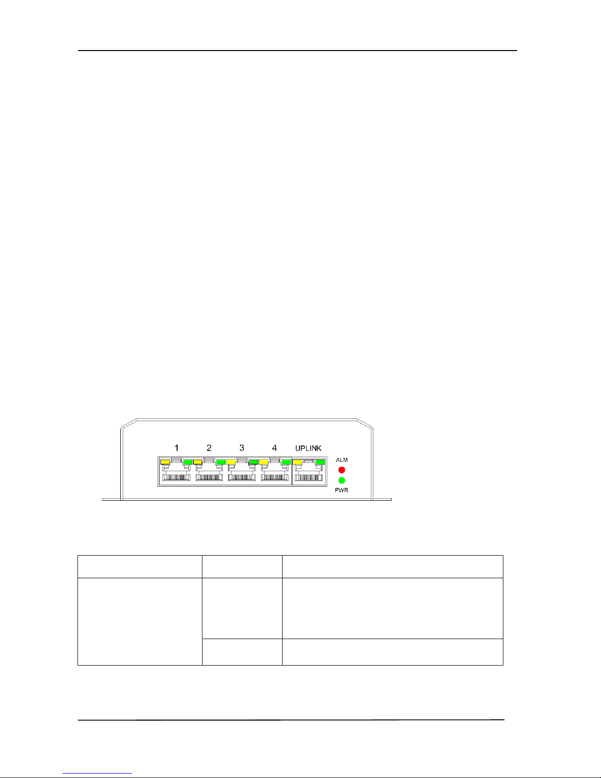
2. Hardware Description
*LED Indicator
There are 12 LEDs on the PoE switch to indicate the status of power and signal. The following
section describes the functions of each LED indicator.
Front panel detail
*POWER LED
LED STATUS Description
Power
Green
LED ON when power input (DC IN on rear
panel or UPLINK on front panel) has valid
power supplied.
Off No power supplied.

User’s Manual PSE-SW5G25B4HM
MSTRONIC CO., LTD.
3
*SWITCH LED (the right indicator on RJ45)
LED STATUS Description
P1~P5
Link/Act
Green
A network device is detected (1000Mbps), but no
communication activity is detected.
Green
Blinking
This port is transmitting to, or receiving package
from another device at 1000Mbps.
Yellow A network device is detected (10Mbps or
100Mbps), but no communication activity is
detected.
Yellow
Blinking
This port is transmitting to, or receiving
package from another device at 10Mbps or
100Mbps.
Off No device is detected.
*PoE LED (the left indicator on RJ45)
P1~P4
PoE Out
Yellow
A valid Powered Device (PD) is detected and
delivering power on this port.
Off
No PD is detected on this port.
UPLINK (P5)
PoE In
Yellow
Powered from another PoE,
Powered via all 4 pairs.
Yellow
Blinking
Powered via 2 pairs, data pairs (pin 1,2,3,6) or
spare pairs (pin 4,5,7,8) are all acceptable.
Off No power is detected on this port.

User’s Manual PSE-SW5G25B4HM
MSTRONIC CO., LTD.
4
*Power wiring
The PoE switch allows to be powered by another PoE source on port 5 (UPLINK) and/or on rear
terminal,
If powered on port 5 (UPLINK) as a PoE repeater, the PoE input must be 44~57VDC, the input
current should not be over 2Amp.
Powered on rear terminal, please make sure the input current isn’t over 15Amp, otherwise will burn
the internal fuse.
Please note green connector is capable of 12A max. If more current is required, use 4 pin DIN
connector for up to 15A.
Model
Input Voltage
(REAR)
Input Voltage
(Port 5)
Output voltage
PSE-SW5G25B4HM
11-36VDC No input
56VDC
(regulated)
No input 44-57VDC
44-57VDC
(non-regulated)
11-36VDC 44-57VDC
56VDC
(regulated)
For PoE operation, total output is 35W (802.3at) x 4 ports. Please note that the full load output is
only when using 24VDC input voltage. If the input is 12VDC, then the total load should be de-rated
to 35W (802.3at) x 2 ports or 17W (802.3af) x 4 ports.
Ports 1~4 will deliver DC power over the Ethernet cable as detailed below:
* Data pair A on line 1 and 2
* Data pair B on line 3 and 6
* Data pair C plus V+ on line 4 and 5
* Data pair D plus V- on line 7 and 8
Port 5 (UPLINK) may receive DC power over the Ethernet cable, as detailed below:
* Data pair A plus V+/V- on line 1 and 2
 Loading...