

MSTRONIC PSE-SW5FSFP24R User Manual

USER’S MANUAL
MSTRONIC CO., LTD.
PSE-SW5FSFP24R
PoE Switch + Media Converter
AC+DC INPUT
User’s Manual PSE-SW5FSFP24R
MSTRONIC CO., LTD.
2
1. General Information
The PoE (Power Over Ethernet) Switch supports four Fast Ethernet ports with PoE injector plus one
100Base-FX up-link port. The switch provides Power over Ethernet functions to deliver 35Watts of
power budget per port to a powered device (PD), which is in compliance with IEEE802.3af/at
standard to deliver both Ethernet data and DC56V power through the traditional UTP or STP cable
to a PD.
2. Hardware Description
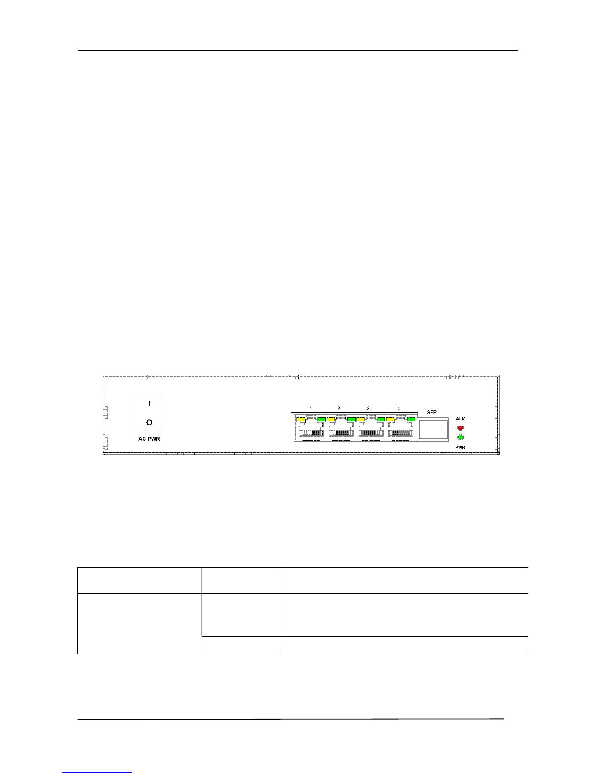
Front Panel
There are 10 LEDs on the PoE switch to indicate the power and operational status and one ON/OFF
switch (for AC power). The following section describes the functions of each LED indicator.
*POWER LED
LED STATUS Description
PWR
(Power)
Green LED ON when power input (AC or DC IN on rear
panel) has valid power supplied.
Off No power supplied.
User’s Manual PSE-SW5FSFP24R
MSTRONIC CO., LTD.
3
*SWITCH LED (the right indicator on RJ45)
LED STATUS Description
P1~P4
Link/Act
Green
A network device is detected, but no communication
activity is detected.
Blinking
@43ms
This port is transmitting to, or receiving package
from another device at 100Mbps.
Blinking
@120ms
This port is transmitting to, or receiving package
from another device at 10Mbps.
Off No device is detected.
*PoE LED (the left indicator on RJ45)
LED STATUS Description
P1~P4
PoE Out
Yellow
A valid Powered Device(PD) is detected and
delivering power on this port.
Off No PD is detected on this port.
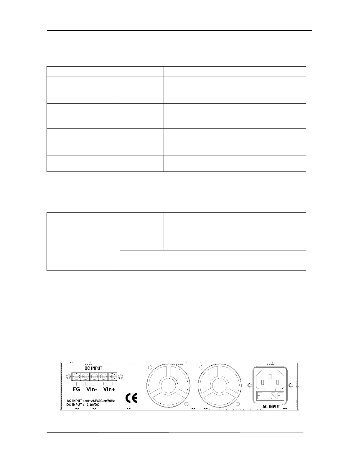
*Rear Panel
The AC inlet, DC input terminal and 2 Ventilation fan are located at the rear panel of the
PSE-SW5GSFP24R. The device will work with AC in the range 90-264VAC, 47-63Hz. It will also
work with DC 24V(12V~36V).
 Loading...