

MSTRONIC MSE PSE-SW5G User Manual
USER’S MANUAL
MSTRONIC CO., LTD.
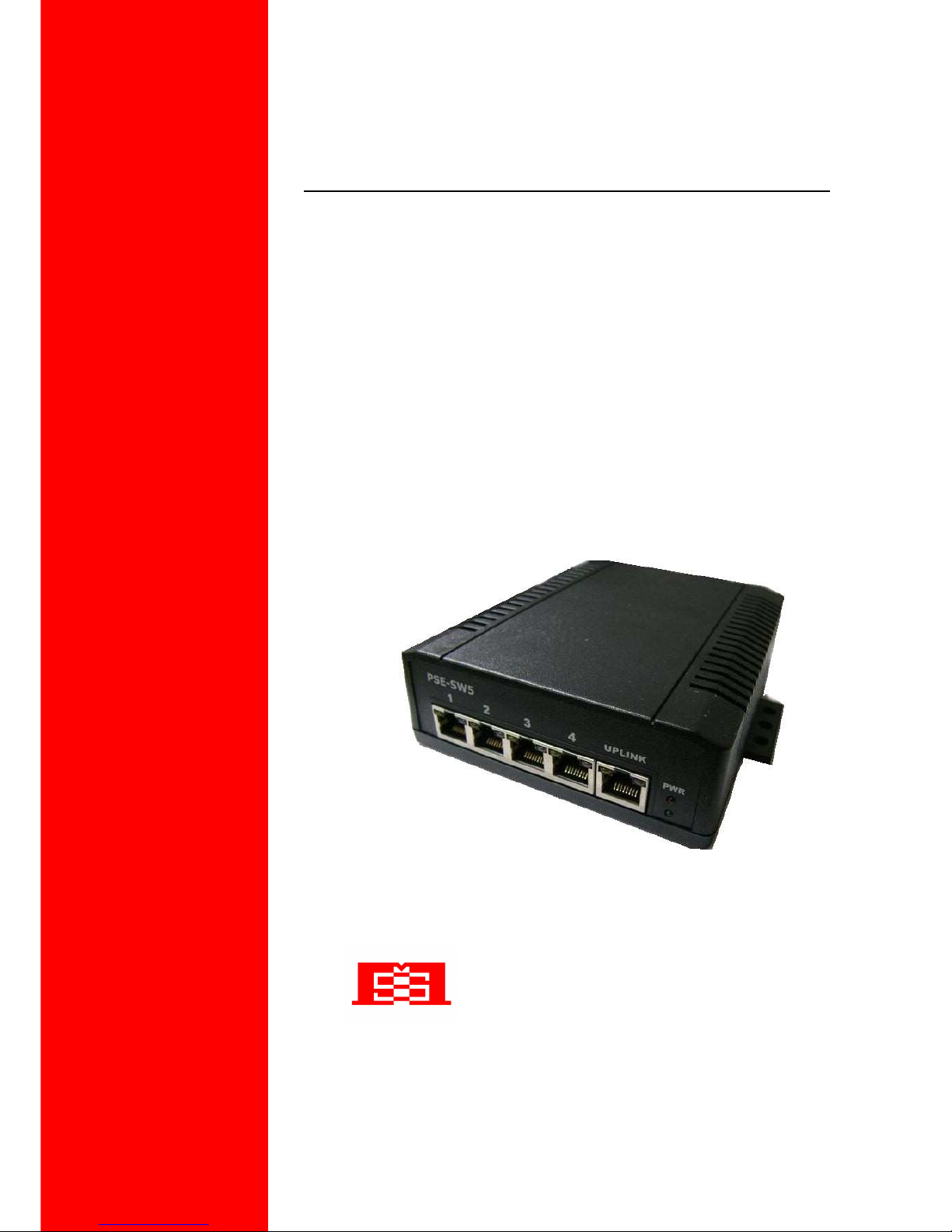
MSE PSE-SW5G
5 Port PoE Switch & Extender
(Repeat Ethernet and PoE)

User’s Manual
MSE PSE-SW5G series
MSTRONIC CO., LTD.
2
1. General Information..............................................................
2. Hardware Description...........................................................
LED Indicators.......................................................................................
Power Wiring ........................................................................................
Ethernet Port Wiring..............................................................................
PD Port Wiring......................................................................................
Network Application……………………………………............................
3. Model Information...........................................................
4. Technical Specification........................................................
3
3
3
5
8
10
11
12
13
User’s Manual
MSE PSE-SW5G series
MSTRONIC CO., LTD.
3
1. General Information
The PoE (Power Over Ethernet) Switch family provide four 10M/100M/1000M TX ports with PoE
PSE function plus one 10M/100M/1000M TX up-link port with PoE PD function. It allows power
souring equipment (PSE) to be powered from PoE and deliver power to PoE powered device (PD),
which are compliant with IEEE802.3af and IEEE802.3at standard to receive and deliver both
Ethernet data and DC power through the traditional UTP or STP cable. The PoE Switch can extend
Ethernet data and DC power up to 200 meters. This manual will help you install and maintain the
PoE switch. Installation of the PoE switch is very easy and you can start to use the product as soon
as you are powered up.
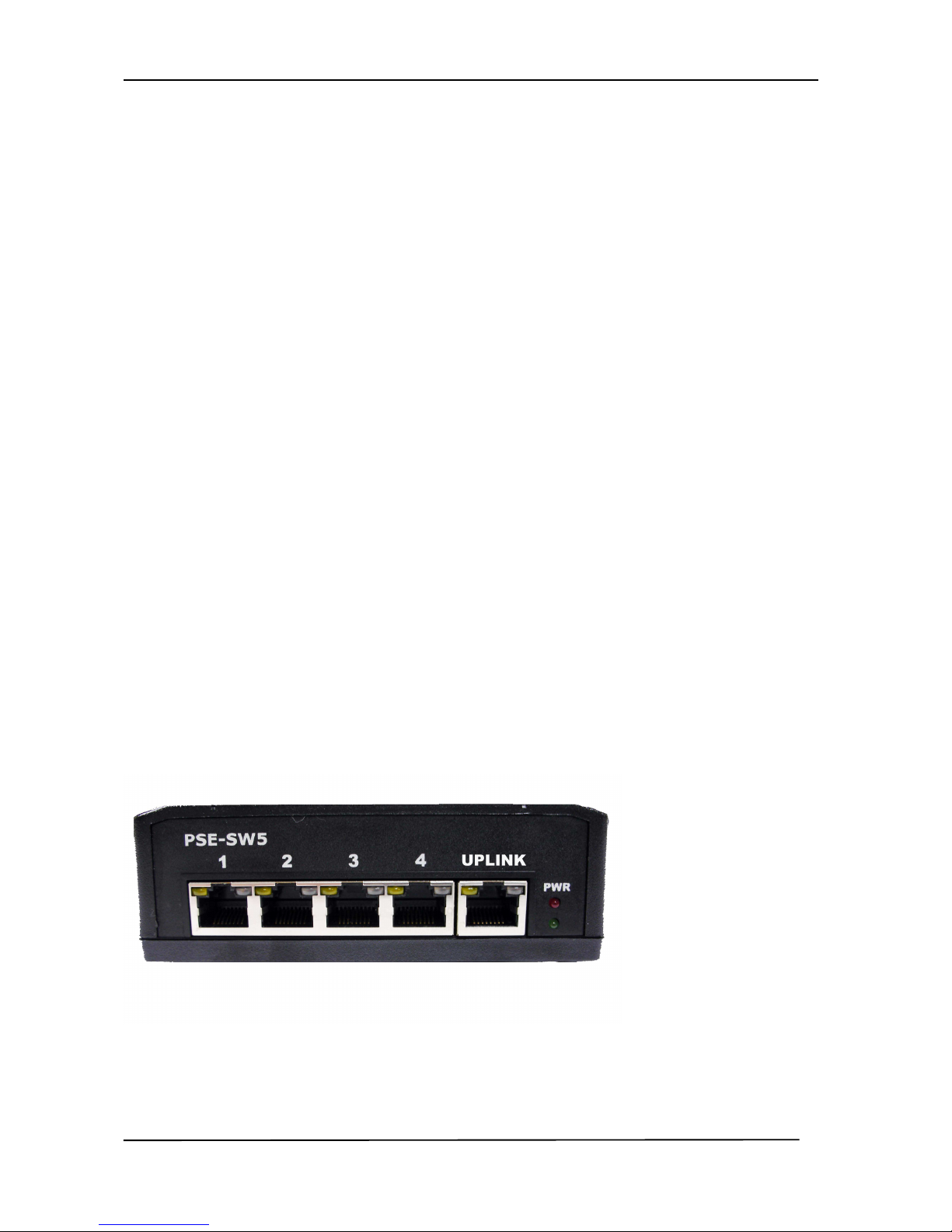
2. Hardware Description
*LED Indicator
There are 12 LEDs on the PoE switch to indicate the status of power and signal. The following
section describes the functions of each LED indicator.
Front panel detail

User’s Manual
MSE PSE-SW5G series
MSTRONIC CO., LTD.
4
*POWER LED
LED
STATUS
Description
Power
Green
LED ON when power input (DC IN on
rear panel or Port 5 (UPLINK) on front
panel) has valid power supplied.
Red
The indicator is only used on
PSE-SW5G11CN, LED ON when the
following warning condition happens.
*Power input under voltage (Vin<10V)
*Power input over voltage (Vin>59V)
*PoE over current (2A/per port)
the indicator is unused on
PSE-SW5G24DN/PSE-SW5G44DN
Off No power supplied.
*SWITCH LED (the right indicator on RJ45)
LED STATUS Description
P1~P5
Link/Act
Green
A network device is detected (1000Mbps),
but no communication activity is detected.
Green
Blinking
This port is transmitting to, or receiving
package from another device at 1000Mbps.
Yellow A network device is detected (10Mbps or
100Mbps), but no communication activity
is detected.
Yellow
Blinking
This port is transmitting to, or receiving
package from another device at 10Mbps or
100Mbps.
Off No device is detected.

User’s Manual
MSE PSE-SW5G series
MSTRONIC CO., LTD.
5
*PoE LED (the left indicator on RJ45)
P1~P4
PoE
Yellow
A valid Powered Device (PD) is detected
and delivering power on this port.
Off
No PD is detected on this port.
UPLINK (P5)
PoE
Yellow
Powered via all 4 data pairs.
Yellow
Blanking
Powered via 2 data pairs. (1,2,3,6 or 4,5,7,8
are all acceptable).
Off No power is detected on this port.
the indicator is unused on PSE-SW5G11CN
*Power wiring
The PoE switch family includes 3 models, be used for 3 different ranges of input voltage:
full range voltage (12 to 57VDC) (P/N: PSE-SW5G11CN)
24VDC typical (12 to 36VDC) (P/N: PSE-SW5G24DN)
48VDC typical (40 to 57VDC) (P/N: PSE-SW5G44DN)
The PSE-SW5G24DN and PSE-SW5G44DN allow power by another PoE source (42.5~57VDC)
on port 5 (UPLINK) as a PoE repeater or extender.
For PoE operation, make sure your power supply may offer at least 75W for 4x 802.3af PoE port, or
150W for 4x 802.3at PoE port.
If powered via the rear terminal, please make sure the input current is not over 10A. If powered on
port 5, make sure the input current is not over 2Amp.
Ports 1~4 will deliver DC power over the Ethernet cable as detailed below:
* Data pair A on line 1 and 2
* Data pair B on line 3 and 6
* Data pair C plus V+ on line 4 and 5
* Data pair D plus V- on line 7 and 8
 Loading...