

Page 1

©Copyright MST Global 2019
User Manual
Revision A, March 2019
Page 2

©
Rev
Revision History
ision Change
A Initial release
AXON Digital Platform
User Manual
Revision A
Date
March 2019
2019 MST Global Commercialin Confidence
ii
Page 3

A
XON Digital Platform
User Manual
Revision A
Copyright and Disclaimer
Copyright
Published in Sydney by: Mine Site Technologies Pty Ltd (MST Global)
ABN: 93 002 961 953 ACN: 002 961 953
Global Head Office : Level 5, 113 Wicks Road, Nor th Ryde, NSW 2141 Australi a
Telephone: +61 (0)2 9491 6500
Copyright © 2019 Mine Site Technologies Pty Ltd (MST Global). All rights reserved. MST Global
reserves the right to make changes to speci ficatio ns and infor matio n in this manual without pri or not i ce.
MST Global ac cepts no respo n s ibility for any err ors or omissions contained in this manu al.
This publication is subject copyright . No part of it may in any form or by any means (electronic,
mechanical, microcopying, photocopying, recording or otherwise) be reproduced, stored in a retrieval
system or transmitted without prior written permission of the copyright owner. Enquiries should be
addressed to MST Global.
Warning
Unauthorised reproducti on o f, alteratio n o f contents, or dist ri buti on to thi r d parti es, in w ho l e or in part is
an infringement of copyright MST Global will actively pursue any breach of its copyright.
Disclaimer
Information contained in this documen t has been de veloped by Mine Site Technologies Pty Ltd (MST
Global). Every care has been taken by the staff of MST to ensure the content of this manual is rel evant
and up to date at the time of publication. Content is subject to change without notice. Technical updates
as associated with this manual will be supplied to the customer at MST Global’s earliest convenience.
This manual is published and distributed on the basi s that the publ i sher is no t responsi bl e for the re sul ts
of any actions taken by users of the information contained in this manual. MST Global does not accept
responsibility for errors or d amag es resulting fr om misrepresentation, misinterpretation or deviation from
instructions by any person in regard to the information contained in this manual. The information is
supplied on the condition that the recipient will make their own determination as to the suitability of the
information for their pu rposes prior to use.
© 2019 MST Global Commercial in Confidence
iii
Page 4

A
Contact Information
Australia
Sydney
Level 5, 113 Wicks Road
North Ryde
Sydney NSW 2113
Tel: +61 (0)2 9491 6500
United States
Denver
13301 W 43rd Drive
Golden, Denver
Colorado 80403
Tel: +1 303 951 0570
Tuscon
Tel: +1 520 495 0185
Chile
Santiago
Vitacura 2771, 0f 503
Las Condes,
Santiago 7550134
Tel: +56 (2) 2 656 7673
Russia
Moscow
Office 318a
Lesnaya, 43
Moscow 127055
Tel: +7 (499) 978 72 11
South Africa
Centurion
Unit 1, Oxford Office Park
3 Bauhinia St
Gauteng 0046
Tel: +27 (0) 12 345 6100
China
Hangzhou
Building 5
1413 Moganshan Road
Hangzhou 310011
Tel: +86 571 8580 3320 Ext 206
XON Digital Platform
User Manual
Revision A
© 2019 MST Global Commercial in Confidence
iv
Page 5

A
XON Digital Platform
User Manual
Revision A
About This Manual
This manual describes features and functions of the MST AXON Digital Platform product family. It
provides information about hardware, installation, configuration an d how to trou bl eshoot any i ssue s. You
will find it easier to use the manual if you are familiar with networking systems and have an
understanding of electronics in a network environment.
Conventions used in the manual
This publication uses the followi ng conv en ti ons to highli ght and conv ey i nforma ti on :
Text that requires input from an operator is boldfaced.
Operator interface screen control names are boldfaced.
Keyboard input keys are CAPITALISED.
Icons
Icons are used in the manual to highlight specific information as shown the table below.
Icon Description
NOTE: The NOTE icon indicates importan t in formation or
references to the user.
IMPORTANT: The IMPORTANT icon con tai ns in formation to prevent
damage to the product and injury to the user.
CAUTION: The CAUTION icon indicates to stop and pay attention
or an action not to be performed.
© 2019 MST Global Commercial in Confidence
v
Page 6

A
Additional Support
For additional support pl ea se visit our website www.mstglobal.com
NOTE: The information provided in this document ("Information") is presented in good faith
and believed to be correct as at the date of this document. MST makes no representations
as to the accuracy or completeness of the Information. The Infor m a ti on is suppl i ed on the
condition that the recipient will make their own determination as to the suitability of the
Information for their purposes prior to use. Under no circumstances will MST be responsible
for any damages whatsoever resulting from the use of, or reliance upon, the Information.
XON Digital Platform
User Manual
Revision A
© 2019 MST Global Commercial in Confidence
vi
Page 7

b
AXON Digital Platform
User Manual
Revision A
Contents
Revision History ......................................................................................................................... ii
Copyright and Disclaimer ........................................................................................................ iii
Copyright ............................................................................................................................................... iii
Warning ................................................................................................................................................. iii
Disclaimer .............................................................................................................................................. iii
Contact Information .................................................................................................................. iv
About This Manual ..................................................................................................................... v
Conventions used in the manual ............................................................................................................ v
Icons ....................................................................................................................................................... v
Additional Support ................................................................................................................................. vi
Chapter 1: Understanding AXON Digital Pl atform .................................................................. 1
1.1 Typical System Layout ................................................................................................................ 1
Chapter 2: AXON Core unit ....................................................................................................... 2
2.1 Hardware Overview .................................................................................................................... 3
2.3 Connectivity ................................................................................................................................ 4
2.3.1 Composite Fibre Ports ........................................................................................................ 4
2.3.2 Copper Ethernet Ports ........................................................................................................ 6
2.3.3 Expansion sockets .............................................................................................................. 6
Chapter 3: AXON Air module .................................................................................................... 7
3.1 Hardware Overview .................................................................................................................... 8
3.3 Daisy Chaining of AXON Air units ............................................................................................... 9
Chapter 4: Network System Design ..................................................................................... 10
4.1 Installation Types and Coverage .............................................................................................. 10
4.2 Power Requirements ................................................................................................................ 10
4.3 Choosing Antennas ................................................................................................................... 11
4.4 Placement of AXON Air units .................................................................................................... 12
4.5 Placement of Antennas ........................................................................................................... 12
© 2019 MST Glo
al CommercialinConfidence
vi
Page 8

A
XON Digital Platform
User Manual
Revision A
4.6 Determining distance between AXON Air modules ................................................................... 13
Chapter 5: Installation .......................................................................................................... 15
5.1 AXON Core Mounting Options .................................................................................................. 15
5.2 AXON Air Mounting Options .................................................................................................... 17
5.3 Antenna Mounting Options ....................................................................................................... 18
5.4 Installation Schemes ................................................................................................................. 20
5.4.1 Installation in a Straight Drive............................................................................................ 20
5.4.2 Installation in a no line of sight scenario ........................................................................... 21
5.4.3 Installation in large underground openings, e.g. Crusher Building .................................... 22
5.4.4 Installation at an Intersection ............................................................................................ 23
5.5 Connecting Power to AXON Core ............................................................................................. 24
5.6 Handling composite cable during installation ............................................................................ 24
5.7 Connecting Composite Cable to AXON Core ........................................................................... 25
5.8 Standard Composite and Fibre Cable Lengths ......................................................................... 25
5.9 Connecting Ethernet Cable to AXON Core ............................................................................... 25
5.10 Connecting Antennas to AXON Air .......................................................................................... 26
5.11 Manual Reset and Reboot ....................................................................................................... 27
Chapter 6: Understanding VLANs ....................................................................................... 28
6.1 Understanding Trunk and Access Ports ................................................................................... 29
6.1.1 Trunk Ports ....................................................................................................................... 29
6.1.2 Access Ports ..................................................................................................................... 29
6.1.3 Port Allocation ................................................................................................................... 31
6.2 VLANs and Wireless Networks ................................................................................................. 31
6.3 Native VLAN ............................................................................................................................. 32
Chapter 7: Configuration Using the Web Interface ............................................................ 34
7.1 Logging onto the Web Browser Interface .................................................................................. 34
7.2 Status Screen ........................................................................................................................... 50
7.2 Configuration Screen ................................................................................................................ 51
7.3 Status Tab ................................................................................................................................ 52
7.3.1 Obtaining Device Information ............................................................................................ 52
7.4 Settings > System > Actions ..................................................................................................... 54
© 2019 MST Global Commercial in Confidence
viii
Page 9

A
7.4.1 Upload/download settings ................................................................................................. 54
7.4.2 Update firmware ................................................................................................................ 55
7.4.4 Reboot .............................................................................................................................. 55
7.4.5 Change password ............................................................................................................. 55
7.4.2 Setting the Time ................................................................................................................ 56
7.5 Setting Tab ............................................................................................................................... 59
7.5.1 Managing Automatic TFTP Configuration ......................................................................... 59
7.5.2 Configuring SNMP S ettings .............................................................................................. 60
7.5.3 Setting Up the LAN ........................................................................................................... 61
7.5.4 Configuring Wireless Radio ............................................................................................... 64
XON Digital Platform
User Manual
Revision A
7.5.5 Configuring Wireless Networks ......................................................................................... 67
7.5.6 Configuring EAP (Extensible Authentication Protocol) ...................................................... 69
7.5.7 Configuring Asset Tracking and Location Based Services ................................................ 70
7.5.8 Configuring Ethernet Switch Ports .................................................................................... 72
7.5.9 Defining VLANs ................................................................................................................. 74
7.5.10 Configuring the VLAN Port Map ........................................................................................ 75
Chapter 8: Centralised Configuration Management ........................................................... 76
8.1 Device Management Overview ................................................................................................. 77
8.1.1 Site Configuration .............................................................................................................. 77
8.1.2 AP Config Templates ........................................................................................................ 78
8.1.3 Access Point ..................................................................................................................... 80
8.2 TFTP Server Overview ............................................................................................................. 83
8.2.1 Editing Site Configuration Files ......................................................................................... 84
8.2.2 Editing Device Configuration Files .................................................................................... 85
8.3 TFTP Parameters ..................................................................................................................... 86
Appendix A: Troubleshooting Guide .................................................................................. 98
Appendix B: Composite Cable Testing ........................................................................ 100
B1: Visual Inspection of the Fibre Optic Cable ............................................................................. 100
B2: Measuring and Testing for Power Loss .................................................................................. 100
Appendix C: Ethernet Cable Specifications .................................................................... 102
© 2019 MST Global Commercial in Confidence
ix
Page 10

A
XON Digital Platform
User Manual
Revision A
Appendix D: Device Discovery ......................................................................................... 103
Appendix E: Connecting a PC to an Network Device ..................................................... 105
Appendix F: Maintenance Check List .............................................................................. 107
Appendix G: Acronyms ..................................................................................................... 108
Appendix H: AXON Core Specifications ......................................................................... 125
Appendix I: AXON Air Specifications ............................................................................ 127
Appendix J: Hardware Warranty ...................................................................................... 130
Appendix K: AXON AIR Installation Addendum .............................................................. 131
© 2019 MST Global Commercial in Confidence
x
Page 11

A
©
XON Digital Platform
User Manual
Revision A
Chapter 1: Understanding AXON Digital Platform
Mine Site Technologies' AXON Famil y o f hardware product s consi sts o f the AXON Core unit and a
number of expansion modules that can be added to it.
There is also a substantial external software offering (sold separately) that complements and
expands AXON hardware, makin g it a true Digit al Plat form for mine di giti zation, automation and
productivity enhancement. Please contact MST for more information in relation to the associated
MST software products.
Currently, in addition to AXON Core, MST offers AXON Air, daisy-chainable, Wi-Fi Access Point with
tracking capability. Two more modules will be added to the family within the next six months.
1.1 Typical System Layout
An example of a typical AXON system deployment is shown on the Figure 1 below.
The first AXON Core in line connects to an Ethernet switch and a power supply via a JB11 junction
box. All subsequent units are connected in series down the mine tunnel by the composite cable.
Optional extension modules and radios, such as AXON Air Wi-Fi access points, are fitted as required.
When the mine tunnel splits into different sections, an additional AXON Core is branched out from the
main network. AXON Core or AXON Air devices can also be positioned in Wi-Fi ‘hot spots’ such as
crib areas and refuge bays. One of the AXON Core devices on the diagra m has an optional PoE+
and power distribution module attached to it, allowing for a bigger number of client devices (such as
cameras) to be connected.
A client device can connect to the network wirelessly when in proximity of AXON Air or directly to
AXON Core via a CAT5 cable.
Figure 1: AXON system layout
2019 MST Global CommercialinConfidence
1
Page 12

©
A
XON Digital Platform
User Manual
Revision A
Chapter 2: AXON Core unit
Topics:
Hardware Overview
Connectivity
This chapter presents the features a nd fun c ti on s o f the AXON Core unit and shows how it integra t es
within a network.
Mine Site Technologies' AXON Core is the main building block of the MST AXON product family. It
consists of a managed fibre optic Ethernet switch with several PoE+ outputs, power management
circuitry for client devices and two sockets for external expansion modules. AXON Core provides
wired network access for mining envi ronments that do not require Intrinsic al ly Safe equipment.
AXON Core has the following key features:
Three, Fibre Optic, Full duplex, Gigabit Ethernet ports
Four 1Gbps copper Ethernet ports with Power over Ethernet (PoE+) supply capability.
Two sockets for external expansion modules (PoE, managed power, automation control, sensors,
etc.)
Rigid hard plastic enclosure, suitable for mining environment, sealed to comply with an Ingress
Protection rating of IP65
Composite cabling system incorporating fibre optic data and DC pow er
Low power design, with a wide input voltage from 20-60VDC
VLAN (IEEE 802.1Q) protocol support
RSTP (802.1W) protocol support
LLDP (802.1AB) protocol support
MST Device Discovery protocol support
SNMP (read only) protocol support
QoS (P802.1p) protocol support
For detailed specifications on AXON Core, see AXON Core Specifications.
2019 MST Global CommercialinConfidence
2
Page 13

A
©
XON Digital Platform
User Manual
Revision A
2.1 Hardware Overview
The features and functions of AXON Core are ill ustrated in Figure 2: AXON Core layout and the
accompanying table.
5
6
3
8
7
4
12
10
1
1
2
9
13 13
4
5
11
10
10
6
14
1
Figure 2: AXON Core layout
Key Description Function
15
14
1
2
Composite ( fibre + power) cable
port
Connector for data transmi ssi on and / or DC power
distribution. There are three ports : A, B and C
Power and Status LED Power and Status LED
3 Power warning LED Power warning LED
4 PoE+ port status dual colour LEDsPoE+ port status dual colour LEDs
5 PoE+ port activity LEDs PoE+ port activity LEDs
6 Fibre port status LEDs Fibre port status LEDs
7 Radio port status LED Radio port status LED
8 Radio port activity LED Radio port activity LED
9 PoE+ AXON Air port
PoE+ port typically used by AXON Air module. It can
also be used for other purposes
10 PoE+ Ethernet ports
External Ethernet por t with IEEE 802.3at PoE+ supply
capability for powering client devices.
2019 MST Global CommercialinConfidence
3
Page 14

A
©
A
A
XON Digital Platform
User Manual
Revision A
11 Factory defaults button
12 Reset button (RED) Pressing this button will cause switch core reset without
13 Mounting holes Rear mounting bracket with holes for mounting AXON
14 Covered Expansion Socket Expansion socket covered with a protective cover.
15 SD card Inserting a card from another switch and power cycling
Factory reset button for the unit. Pressing it for 5…15
seconds will cause factor y reset
losing the device configuration.
Core on the wall or roof.
XON Core will install switch configuration stored on the
card
2.3
Connectivity
AXON Core has three types of network connectio ns:
Composite Fibre Ports
Ethernet Ports
Expansion interfaces
2.3.1 C om posite Fibre Ports
AXON Core unit has three composite fibre port connectors with a crush protection cover. Each
connector consists of tw o electrical contact s and a duplex L C single mode optic fibre (SM OF)
receptacle as shown in Figure 3: Composite fibre ports.
NOTE: A protective cover o r a mating cabl e connector must be attach ed to unused
ports to maintain the IP65 (Ingress Protection) rating of the unit
Figure 3: Composite fibre port s
Each port can be connected in one of the following ways:
Port connection Description
Protective covers
DC power only connection
DC power cable to connect the PSU to the electrical
contacts on an AXON Core. By convention, this cable is
connected to port A.
2019 MST Global CommercialinConfidence
4
Page 15

A
©
A
A
Fibre only connection
XON Digital Platform
User Manual
Revision A
fibre optic cable terminated to the fibre contacts of the AXON
Core composite connector.
Fibre and DC power connection
composite cable providing fibre optic connectivity and power
to AXON Core.
Fibre optic cabling provides numerous benefits over Ethernet cabling, with superior signal integrity
and no signal interference from high-powered electronics. It also enables units to be spaced over
longer distances wi tho ut the di stance limitation of Ethe rnet cabling.
By default, port A is configured as the upstrea m port and ports B, C as the dow nstrea m ports. The
difference between upstream and downstream ports is the orientation of the fibre that is used for
transmitti n g and receiving data. This is illustrated in Figure 4: Fibre orientation of Upstream and
Downstream ports.
Figure 4: Fibre orientation of Upstream and Downstream ports
Due to the difference in the fibre orientation, M ST composite cable an d fib r e optic cab l e can only be
connected between ports on AXON Core devices marked with a tick in the matrix below.
Port A
Port A Port B Port C
Port B
Port C
Single- and Multi-Mode Cables
AXON Core is supplied from the factory with 1000BASE-LX single-mode SFP modules. Customers
wishing to interface to other cable standards, e.g. 100BASE-FX single or multi-mode, should con t act
MST to arrange replacement of the appropriate SFP modules.
2019 MST Global CommercialinConfidence
5
Page 16

A
©
XON Digital Platform
User Manual
Revision A
NOTE: If replacing the single-mode SFP modules wi th mul ti-mode modules, the
single-mode patch lead between the SFP module and the MST Composite Cable
connector on the inside of the housing needs to be replaced w i th a multi-mode
patch lead.
JB11 junction boxes can be connected inline between any two units in the chain
to supply power. There is no need to isolate AXON Core units to a single power
source.
IMPORTANT: If an SFP is changed, the device must be rebooted or reset to
detect the change.
2.3.2 Copper Ethernet Ports
AXON Core has four external Copper Ethernet ports that enable connection to other networking
devices.
The four Ethernet ports also provide IEEE 802.3at PoE+ (Power over Ethernet) injector functionality,
allowing a singl e cable to be used for data a nd power to network devi ces. Each Ethernet port's
functionality can be configured by the w eb browser inte r face, or by centralised configuration
management.
One of these four ports, located on the top of AXON Core, will typically be used for AXON Air module
connection, but can also be used for any other purpose. Similarly, any of the other PoE+ ports can be
used to connect AXON Air module.
For more information on configuring Ethernet ports, see Chapter 7: Configuration Using the Web
Interface
2.3.3 Expansion sockets
AXON Core has two expansion sockets on its front panel that allow adding optional expansion
modules to it.
Expansion socket
cover
2019 MST Global CommercialinConfidence
Expansion socket
interface
6
Page 17

©
A
XON Digital
Platform
User
Chapter 3: AXON Air module
Topics:
Hardware overview
Daisy Chaining of AXON Air units
This chapter presents the features and func ti on s o f the AXON Air module and shows how it
integrates with the AXON Core unit and the networ k.
Mine Site Technologies' AXON Air is a key member and an important building block within the MST
AXON family of products, it provides wireless network access for mining environments that do not
require Intrinsically Safe equipment and consists of a Wi-Fi Access Point and 2-port Ethernet switch
for daisy chaining. AXON Air supports meshing (802.11s protocol) and can be used as a mesh
gateway or a wireless bridge between two wired subnets.
AXON Air has the following features:
One Wi-Fi Radio, 802.11 a/b/g/n, 2 x 2 MIMO, 2.4 or 5Ghz
6 x SSIDs
VLAN (IEEE 802.1Q) protocol support
LLDP (802.1AB) protocol support
SNMP (read only) protocol support
QoS (P802.1p) protocol support
WEP/ WPA/ WPA2 security protocols support
Two 1Gbps Ethernet ports with proprietary Power over Ethernet power supply capability
The unit gets its power from the upstream PoE ports and pas ses it throu gh to the next access
point in the chain via the downstream port. AX ON Ai r negotiates a P oE + Cl ass 4 power
requirement, whilst drawing 4W nominally.
Rigid hard plastic enclosure, suitabl e for mini ng environment sealed to comply wi th an Ingress
Protection rating of IP65
For detailed specifications on AXON Air, see AXON Air Specifications
2019 MST Global CommercialinConfidence
7
Page 18

©
A
A
XON Digital Platform
3.1 Hardware Overview
The features and functions of AXON Ai r are illustrated in Figure 2: AXON Air layout and the
accompanying table.
User Manual
Revision A
Figure 2: AXON Air layout
Key Description Function
1 Upstream PoE+ Ethe rnet po rt
2 Downstream PoE+ Ethernet p ort
1xGbps Ethernet port with IEEE 802.3at PoE+ input
capability
1xGbps Ethernet port with IEEE 802.3at PoE+ supply
capability for power i ng next - i n- line AXON Air unit
3 Default configuration button Pressing the button for 10 or more seconds and
power cycling AXON Air at the same time will cause
4
factory reset
ntenna connector N-type female Antenna connectors
5 Power On LED Power On LED
6 Wi-Fi Activity LED Wi-Fi Activity LED
2019 MST Global CommercialinConfidence
8
Page 19

©
A
A
XON Digital Platform
7 Downstr eam PoE L ED Downstream PoE activity LED
8 Upstream PoE LED Upstream PoE activity LED
9 Tracking activity LED Tracking activity LED
10 External Antenna External 2.5dB, omnidirectional antenna
User Manual
Revision A
11
ntenna swivel mounting area Mounting area used to accommodate optional
antenna swivel mechanism (sold separately).
12 Mounting holes Two mounting holes on the top of the module
3.3 Daisy Chaining of AXON Air units
Each AXON Air features a two-port Ethernet switch, which enables daisy chaining of individual AXON
Air units via a CAT5 cable. The maximum distance in between AXON Air nodes in such scenario is
100 meters. A maximum of three AXON Air units can be daisy chained together.
The unit gets its power from one of its upstrea m P oE port and passes i t thr ough to the next access
point in the chain via the downstream port. AXON Air negotiates a PoE+ Class 4 power requirement,
whilst drawing 4W nominally.
The AXON Air operational parameters can be configured through its o wn web brow ser interface or via
the centralised configuration management. For more information, see Chapter 7: Configuration U sing
the Web Interface
2019 MST Global CommercialinConfidence
9
Page 20

©
A
XON Digital Platform
User Manual
Revision A
Chapter 4: Network System Design
Topics:
Installation Types and Coverage
Power Requirements
Choosing Antennas
Placement of AXON Air units
Pla c eme nt of Antenn as
Determining distance between AXON Air modules
This chapter describes network system design for underground mines.
A MST System Engineer will usually design and preconfigure a network based on the requirements
and layout of each mine site. This will involve a visual inspection of the mine site to identify user
areas, and determine access point locations. A RF (Radio Frequency) site survey is also conducted
to understand the behaviour of radio waves in the mine. The following factors help determine network
design:
Wireless coverage re quirements of the mi ne
Quantity and type of wireless client devi ces conne cted to the network
Wired client devices connected to the network and their location
Interconnection to the mine's exi sti ng corpo rate network
Policies for network protocol between networks
Cabling requirements
Antenna types to use w ith each unit an d mounti ng method for ea ch antenna
Mounting location and installation method for each network device.
4.1
Installation Types and Coverage
Wireless network coverage can be described as:
Wi-Fi hotspot — Network coverage is provided in key areas, such as crib areas and refuge bays.
Full coverage — Seaml ess wi reless cov era ge by strate gical ly placi ng AX ON Air units so their
radio fields overlap.
An AXON Air can communicate at wireless distances of 150-30 0 metres, depending on the chosen
antenna,geometry and geology of the mine.
4.2
Power Requirements
The power requirements for a networ k are unique to each site installation. Det ermining power
requirements can be complex and is dependent on various factors such as the number of AXON Core
units, PoE devices, branches in the network and composite cable lengths.
2019 MST Global CommercialinConfidence
10
Page 21

©
A
A
A
A
v
XON Digital Platform
User Manual
Revision A
NOTE: A site inspection conducted by a MST System Engineer will help determine
the power requirements for your network.
AXON Core is designed t o opera te a t a w i de v ol tage ran ge, fro m a mi ni mu m o f 20VDC u p to 60VDC.
Each AXON Core in a network can interna lly step u p the incoming voltage to 48VD C in order to
supply power to its connected PoE devices. AXON Core needs to receive a minimum input of 20VDC
to power PoE devices.
56VDC power supplies are used for large networks to maximise the distance between power
supplies. For instances where the AXON Core switches are deployed in isolation or in remote
location a 24V DC UPS can be used.
External power supply reco mmendations:
Using Uninterrupted Power Supplies is not mandatory; however, it will increase the uptime and
protect the network from power surges and fluctuations. Fluctuations may cause damage to the
network and auxiliary equipment. The recommended UPS is AXO N Force UPS.
4.3
Choosing Antennas
Antennas are connected via N-Type connectors to each AXON Air to provide wi reless network
coverage. The type of wireless coverage, surrounding geology, tunnel topology and surface of the
roadway/tunnel are all factors that will determine the choice of antenna. A minimum of two antennas
is required for each AXON Air. There two most popular directional antenna patterns:
Omnidirectional antenn as — radiate equ ally in all direct ions for a short ran ge, providing
immediate coverage in an open area.
Directional antennas — radiate in a specific direction over a longer range. A higher gain antenna
will have a longer range an d is more directional. It is important that directional antennas are
aligned properly betw een AXON Air units to en su re conti nuou s coverage between uni ts.
The antenna radiation pa ttern and polarisa tion need to be con sidered to prov ide suitable wirel ess
coverage in an area.
Antennas commonly used with AXON Air are shown below.
ntenna Type Illustration Description
Omnidirectional 2.5dbi
rubber whips
lower gain antenna that radiates equally in
all directions. It provides direct cov erage in an
open area.
Panel antenna
panel antenna is a directional antenna, with
a wide horizontal beamwidth and narrower
ertical beamwidth. They are suited for
covering an open area in one direction.
2019 MST Global CommercialinConfidence
11
Page 22

©
A
A
Y
A
Diversity panel antenna
agi directional antenna
XON Digital Platform
User Manual
Revision A
diversity panel antenna contains two panel
antennas in one housing with a 90° rotation
between them. It is used for providin g bett er
signal reception in difficult areas, and more
accurate Wi-Fi tag location when Wi-Fi
tracking is implemented. Diversity antennas
use both antenna connections on a WAC.
Ya gi antenna is high gain directiona l
antenna. They are ideally suited for line of
sight tunnel communications. Yagi antennas
need to be aimed accurately and avoid
obstacles in their RF beam path.
4.4
Placement of AXON Air units
In underground environments, many factors can influence finding a suita ble location for moun ting of
the AXON Air access point and antennas connect ed to it. This docu men t wi l l only consi der the signal
propagation aspects, se e AXON Air Mounting Options for more advice.
4.5
It is recommended to attach the antennas directl y , or with a short good qu al i ty coax i al cable, to the
access point. The antenna can be connected up to 20m away from the access point when at
minimum CNT or LMR 400 antenna cable is used. At 2.4 GHz the loss of this cable is approximately
2.1 dB per 10m. It will reduce the effectiveness of the antenna however it may be acceptable with the
use a of high gain antenna. The coaxial connection should be kept as short as possible to minimise
signal attenuation. Large r anten na s / longe r cabl e feeds can re qui re l i ne am pl i fie rs, and possi bl y bidirectional splitter / combi ner s for dual antenna systems.
In surface installation to ensure EN 60950-1 compli an ce, AXON Air, the antenna and all cabli ng m ust
be installed in a location that eliminates the chance of the system being struck by lightning. If an
antenna needs to be installed in a location whe re i t could be struc k by lightni ng, then an app ropri ate
lightning arrestor must be placed in-line with the antenna and cabling such that AXON Air is not
subject to overvoltage due to lightning.
Antenna placement underground is dependent on the surrounding geology, tunnel topology and
stratum type. The recommended place men t o f antennas is as foll ows:
Tip 1: Directionality
Antennas should be mounted and angled to give optimum transmission along curves and dips as
shown below in Figure 5: Angling antennas.
Placement of Antennas
Figure 5: Angling antennas
2019 MST Global CommercialinConfidence
12
Page 23

©
A
XON Digital Platform
User Manual
Tip 2: Obstructions
Antennas should be mounted to avoid signal obstructio n fro m roc k, veh i cles, equipment and
machinery as show n in Figure 6: Antenna mounting to avoid obstructions.
Revision A
Figure 6: Antenna mounting to avoid obstructions Tip 3: RF Field Overlap
Multiple antennas should be mounted to av oid crossing signal paths as shown in Figure 7: Antenna
directivity.
Figure 7: Antenna directivity
The positioning of the antennas is crucial when Wi-Fi tags are used for asset tracking and locati on
services. Wi-Fi tags wil l not be read when there are anten na standi ng wave nulls. Antennas need to
be positioned to have best reception of tag messages. For Antenna mounting options, see Antenna
Mounting Options
4.6 Determining distance between AXON Air modules
Line of Sight Distances
In line of sight, each AXON Air has a maximum wireless range of 300 metres (984 feet) using high
gain directional antennas . AXON Air unit s are gen erall y i nstall ed wi th a 100 metre (328 feet) ov erla p
of the radio field as shown in Figure 8: Wireless channel layo ut and distances around curves
2019 MST Global CommercialinConfidence
13
Page 24

A
©
XON Digital Platform
User Manual
Revision A
This ensures sufficient coverage between AXON Air units.
AXON Air units within ran ge of each other must be configured w ith different Wi-Fi channels. B y default
every fifth channel is used (channels 1, 6 and 11) to prevent signal overlap, minimising the possibility
of inter-modulation or inter ference. There are ci rcumstances in which the configuration may all ow all
radios to be operating on the same channel. Rapid handover and mobi l e dev i ce battery consu mptio n
may improve in this configuration.
Figure 8: Wireless channel layout and distances around curves
In situation where line of sight (LoS) between the receiving device and AXON Air cannot be achieved
due to the physical layout of the tunnel, the distan ce betw ee n the AP’s may need to be reduced.
Below is a typical example of such situation. The AXON Air AP’s are spaced 100 m apart to
overcome the curvature of the spiral decli ne
There are many variances in a tunnel, which
influence the RF signal propa gation, the si z e
and curvature being the most prevalent. The
surface of the walls, steel mesh, water and
objects in the RF path are all factors to take
into consideration when planning the system
design. Another important factor to consider
is movement of vehicles, large vehicle such
as trucks can shadow a large area of the
section of the tunnel, effectiv ely bl ocking the
roadway and the RF path. In many cases, it
is advantageous to trial a section to get a
better understanding of the Wi-Fi
propagation in the specific environ ment . A
Wi-Fi survey is a good measure to insure
good coverage.
2019 MST Global CommercialinConfidence
14
Page 25
©
AXON Digital Platform
User Manual
Revision A
Chapter 5: Installation
Topics:
AXON Core Mounting Options
Antenna Mounting Options
Installation Schemes
Connecting power to AXON Core
Handling Composite Cable During Installation
Connecting Composite Cable to AXON Core
Standard Composite and Fibre Cable Lengths
Connecting Ethernet Cable to AXON Core
Connecting Antennas to AXON Air
Manual Reset and Reboot
This chapter describes mountin g opti on s, installation schemes, and antenna and cable connecti o ns.
Fibre connector assembly and cable termi nati on are bey ond the scope of thi s manua l .
IMPORTANT: The electronic components in each AXON Core have been designed to
be isolated from the enclosure and local electrical earth. This ensures there is no
5.1
Standard mounting options for AXON Core are described in the table below.
The mounting plate for AXON Core is designed for ease of installation and future convenient
removal/replacement. The key holes in the mounting plate allow AXON Core to be attached or removed
from the plate with ease; there is no need to remove the mounting plate when exchanging an AXON
Core in place of a new one.
AXON Core Mounting Options
current passing between grounds of different potentials (known as galvanic isolation).
Galvanic isolation must always be maintained, with the AXON Core ground terminals
isolated from electrical earth , and all antenna and an tenna cab l e connec ti o ns prope rl y
insulated.
Application Installation
Mounting the AXON Core Mounting plate to a
rock bolt
The AXON Core mounting plate has two 25mm
holes to mount it to a rock bolt on the mine's
rock face. It is secured to the rock bolt with a
Mounting the AXON Core Mounting plate with 12
mm rock anch or or thr e aded ba r .
25mm nut.
Drill 13 mm hole and use appropriate chemical
anchor to secure the anchor rod
Mounting AXON Core to the mesh The four corner mounting points on a mounting
plate can be cable-tied to the mesh in a mine
tunnel.
2019 MST Global CommercialinConfidence
15
Page 26

©
A
XON Digital Platform
User Manual
Revision A
The AXON Core mounting plate
Step 1. Drill 13 mm hole Step 2. Inject glue
Step 4. Mount the AXON Core
Plate Step 3. Insert both Anchors
2019 MST Global CommercialinConfidence
16
Page 27

©
A
XON Digital Platform
User Manual
Revision A
Step 5. install AXON Core & Air
CAUTION: The above mounting method maybe not suitable for your particular
situation. If in doubt consult with your Geo-Technical team or your supervisor.
The AXON Core mounting plate can be
mounted in various convenient ways.
On this picture you can see a preferred
way of using two 12 mm chemical
anchors.
Any combination may be used to fix the
plate e.g. 24 mm rock bolt and 12mm
chem anchor.
5.2
AXON Air Mounting Options
The AXON Air wireless access point is commonly mounted onto the AXON Core unit as depicted at
Step 5 in the previous paragraph. There will be situations where it is advantageous to mount AXON Air
in a different location to AXON Core or where AXON Core is not required, e.g. when AXON Air is
chained to another AXON Air. For this purpose, a separate mounting plate is included with AXON Air.
A convenient way to mount AXON Air is to use a mounting post as shown on the photo below. The
procedure is similar to the AXON Core mounting method shown above. The 12mm threaded anchor (WMNT-025) is glued into a hole in the rock wall and the yellow mounting post ( W-MNT-019 ) wi th A XO N
Air attached to it is screwed on top of the anchor. A M12 nut can be used to counter lock the pole,
stopping it from spinning, if required.
The mounting plate has two key holes that are used for wall or rock face mountin g.
AXON Air Mounting Bracket
2019 MST Global CommercialinConfidence
17
Page 28

©
A
XON Digital Platform
User Manual
Revision A
Note: When mounting AXON Air wireless access points, it is important to
consider the distance from the antenna to sur rounding objects. As a rule
generally, antenna should not be placed within 400 mm of RF reflecting objects
or materials that contain metal.
CAUTION: The above mounting method maybe not suitable for your particular
situation. If in doubt consult with your Geo-Technical team or your supervisor.
5.3
Antenna Mounting Options
Antenna mounting is dependent on the location and cov erage requi red . E xamples of antenna installatio n
options are described and illustrated in the table below.
Mounting Option Description Picture
Omni directional
antenna directly
attached to AXON Air
AXON Air is supplied with 2x
2.5 dBi Omni directional
antennas. Which install
directly to the enclosure.
Directional Helical
antenna 15 dBi
(Poynting) directly
attached to AXON Air
Example of a directional
Helical antenna directly
attached to AXON Air. This
is the preferred mou nting
method and has the
advantage of a short RF
cable.
2019 MST Global CommercialinConfidence
18
Page 29

©
A
Mounting a Yagi
antenna or panel
antenna to the mine
tunnel roof.
In instances where it is
required to separate the
antenna from AXON Air, an
antenna can be connected
via an (up to) 20 m Coaxial
cable.
A hole is drilled into the
tunnel roof and the mounting
pole is secured using
chemset adhesive. The Yagi
antenna is attached to the
mounting pole using Uclamps
XON Digital Platform
User Manual
Revision A
Mounting a Yagi
antenna or panel
antenna at a portal
Mounting a panel
antenna on the rock
face or mesh
In situation where the drilling
is not possible or prohibited,
specialised mounts can be
manufactured.
The panel antenna is cable
tied to the mesh, ensure the
antenna is not obstructed by
objects and avoid mounting
it close (400 mm or less) to
large steel structures.
2019 MST Global CommercialinConfidence
19
Page 30

©
A
XON Digital Platform
User Manual
Revision A
5.4
Installation Schemes
The installation and placement of antennas and AXON Core units will depend on the wireless coverage
type, rock type and tunnel topology. A few examples of installation schemes in a mine are described and
illustrated in the following sections.
5.4.1 Installation in a Straight Drive
An example of a straight driv e installation sche me is show n in Figure 9: Installation scheme in a straight
drive.
In this example, multiple AXON Core units are fitted with AXON Air access points utilising 15dBi helical
antenna. This creates constant coverage as may be required by a vehicle traveling along the roadway.
Figure 9: Installation scheme in a straight drive
2019 MST Global CommercialinConfidence
20
Page 31

©
A
XON Digital Platform
User Manual
Revision A
5.4.2 Installation in a no line of sight scenari o
A curved decline installation scheme as shown in Figure 10
One of the advance d futures of AXON Air is the ability to b e powered from anoth er AXON Air. This adds
great flexibility in network desi gn. In the ex ample bel ow a AXON Core network switch is collocated i n the
electrical cuddy, this is con venient as the composite cable can be run through a borehole from the
surface and then further to the lower level s. It is not recommend to chain more tha n 3 AXON Air u ni ts
from one PoE+ port on AXON Core. The maximum length of Ethernet cable between AXON Air units is
100 meters, this gives 300 meters if 3 units were chained.
Figure 10: Installation scheme in a curved decline
2019 MST Global CommercialinConfidence
21
Page 32

©
A
XON Digital Platform
User Manual
Revision A
5.4.3 Installation in large underground openings, e.g. Crusher Building.
In large openings, it is advan tageous to use omni- di rectiona l or semi-di recti on al anten na. The exam pl e
here shows AXON Core unit with AXON Air module providing wireless network coverage and PoE
connectivity. AXON Core functi onal i ty i s ex pand ed wi th two optional (soon to be rel eased) pl ugin
modules. Firs t called AXON Control providing autom a t ion capability and the second called AXON
Power, which expands the total number of AXON Core PoE ports to seven.
On the diagram below, there are six IP cameras connected to AX ON Cor e, tw o of which monitor t he
crusher and the other four monitor t rucks reversing towards the crush er. AXON Control module connects
to the sensor measuring the temperature of the main bearing of the crasher, it also drives the crusher
dust suppression solenoid valve via one of its relay outputs. The automation logic, driving the relay is
enabled by the MST SENSA Director software. The dust suppression is turned on only when a truck is
present.
Figure 11: Installation scheme in a Crusher Building
2019 MST Global CommercialinConfidence
22
Page 33

©
A
XON Digital Platform
User Manual
Revision A
5.4.4 Ins tallation at an Intersection
An example installation scheme for an intersection is shown in Figure 12: Install ati on Scheme at an
intersection.
At intersection where fibre connection i s requi red to be conti nued i n all directions, tw o AXON Core
Nodes are required. The distan ce fro m the in terse cti on depends on the s p eci fic re qui rements.
It may be appropriate to move one AXON core with AXON Air attached to it (B) as far as 400 m into the
northern spore roadway and the other (A) in the orthogonal direction closer to the intersection.
A traffic light solution can be implemented if an optional AXON Control module is used inside of the unit
(A). It can be programmed to operate independently of the network.
B
N
A
Figure 12: Installation Scheme at an intersection
2019 MST Global CommercialinConfidence
23
Page 34

©
A
XON Digital Platform
User Manual
Revision A
5.5
Connecting Power to AXON Core
The AXON family of products includes three ru ggedi zed mining uninterrupted power supplies, for f ul l
composite cable installation in operational areas AXON Force is an ideal UPS. The main electrical
benefit is that the output power is 56V DC constant, regardless if mains power is available or not. Most
common UPSs will supply 56V DC if mains power is on; however, the output voltage will drop back to 48
V DC when mains power is off. This means that the DC power design has to consider worst-case
scenario.
MST strongly recommends the use of UPS in underground implementation, as it will ensure clean
reliable DC power and guarantied uptime.
Composite cable can be inserted into other AXON Cores while the system is powered; this allows the
system to be expanded as necessary. Power usage levels should be evaluated prior to adding more
units downstream to ensure that the v ol tage rail doe s not drop too low . A minimum of 20VDC is required
for AXON Core to supply PoE to other dev ices. If the voltage drops below 20 V , additi on al po wer is
required.
The DC power system is dose not allows more than one DC Supply/UPS to be
connected to the same composite cable. This is r e ferred to as “cell” cell s are
interconnected via optical fibre connection only. This typical for DC systems. If
double redundant power is required, please contact MST.
Connect the composite fibre/power cable to a DC power source with correct termination. Note that the
DC supply must be between 20 and 60VDC. Refer to the power supply requirements Section 4.2.
Turn on the DC power supply and verify that the green power ligh t is on. If there i s no green light, refer to
Troubleshooting Guide.
5.6
Handling composite cable during installation
The composite cable is ruggedly buil t for the mining envi ronmen t . How ev er the foll ow i ng precautionary
measures should be noted during instal l ation:
Never pull or create tension on the cable. Unreel the cable from the cable reel, or allow the weight of
the cable to unreel as the vehicle is moving as shown in Figure 13: Handling composite cable.
Do not bend the cable at sharp angles; excessive bending can fracture or break the fibre optic cable.
Do not step on the cable.
2019 MST Global CommercialinConfidence
24
Page 35

©
A
XON Digital Platform
User Manual
Revision A
Figure 13: Handling composite cable
5.7
Connecting Composite Cable to AXON Core
A composite cable is connected to the fibre port of AXON Core. Once connected, it will auto detect
devices and their settings.
IMPORTANT: Protect al l conne ctors and sockets from dust and grit, with minimal
exposure during installation. Any unused sockets must be cov ered by the sup pl i ed
dust caps at all times during installation. Any unused sockets must be covered by
the supplied dust caps at all times.
Branch fibre network out requires simpl y con necting composite cables to the addition al fibre por ts. The
connected fibre ports wil l cause the correspondi ng fibre port LEDs to become active. If you are adding
AXON Core units to an existing system, please consult your MST System Engineer to ensure power
requirements are being met.
5.8
Standard Composite and Fibre Cable Lengths
While custom cable runs can be made whe re necessary, it is faster and cheaper to use standard cable
lengths supplied by MST. Please contact MST for the latest listing of available cable lengths.
5.9
Connecting Ethernet Cable to AXON Core
The external Ethernet po rts are loca ted on the un derside o f AXON Core, and are used to connect to
Ethernet devices (such as computers, Ethernet controlled PLCs, ha rd-wired Etherne t Phones and IP v ideo
devices). An Ethernet cable with a RJ45 connector is used to connect PoE de vices. Ethernet cables are
required to meet specifications for use in a mining environment in Ethernet Cable Specifications
2019 MST Global CommercialinConfidence
25
Page 36

©
A
Procedure Illustration
1. Unscrew the protective cover on the
Ethernet port.
2. Insert the Ethernet cable (with a bayonet
back-shell)
3. Align the protective cover on the cable to the
notch in the mating jack on AXON Core, and
twist to lock the connector into the Ethernet port
4. Securely fasten the cable lead against the
wall/ceiling.
IMPORTANT:
Check that all unused Ethernet ports
remain protected with the supplied
covers.
XON Digital Platform
User Manual
Revision A
5.10
Connecting Antennas to AXON Air
Antennas can be connected directly to the coaxial (RP-TNC) jacks on the unit or mounted remotely by
using coaxial cables. Coaxial cable length should be kept as short as possible (ideally less than 10m) to
minimise signal loss.
IMPORTANT: All cable and antenna connections must be electrically insulated using selfamalgamating rubber tape.
To ensure EN 60950-1 compliance, AXON Air, the antenna and all cabling must be installed in a
location that eliminates the chance of the system being struck by lightning. If an antenna needs to
be installed in a location where it could be struck by lightning, then an appropriate lightning arrestor
must be placed in-line with the antenna and cabling such that AXON Air is not subject to
overvoltages due to lightning.
2019 MST Global CommercialinConfidence
26
Page 37

©
A
XON Digital Platform
User Manual
Revision A
5.11
Manual Reset and Reboot
The AXON Core switch fabric can be manually reset or the whole device can be loaded with default
settings as described below .
Description Picture
Locate and identify the switch Reset Button (RED).
Press and release to reset the switch core
Description Picture
Locate and identify the Default Factory Settin gs
Button (BLACK).
To reset AXON Core to factory default settings,
pres s a n d ho ld th e b u t to n f o r 5 … 15 se c on d s.
2019 MST Global CommercialinConfidence
27
Page 38

©
A
XON Digital Platform
User Manual
Revision A
Chapter 6: Understanding VLANs
Topics:
Understanding Trunk and Access Ports
VLANs and Wireless Networks
Native VLAN
This chapter explai ns the principles behind a Virtual Local Area Network (VLA N). It is important to
understand VLANs to properly configure the network and power distribution module.
A VLAN is a collection of nodes grouped according to their function or application, rather than their
physical location. They are grouped in order to separate and prioritise data within a network, as shown in
Figure 14: VLANs. VLANs are created when multiple applications, such as voice, telemetry, data and
video, are required in a mining network.
Figure 14: VLANs
2019 MST Global CommercialinConfidence
28
Page 39

©
A
XON Digital Platform
User Manual
Revision A
6.1
Understanding Trunk and Access Ports
VLANs can be assigned to trunk ports and acces s ports on a netw or k. Th ese two types of alloca tion
determine how data is transmitted and relayed.
6.1.1 Trunk Ports
Trunk ports typically provide a connection between network switches, and can carry data for multiple
VLANs. They will only tran smi t frames (packets of data) that belong to the port's assigned VLAN s. To
identify the VLAN of each frame, a network switch adds a tag to the fram e (know n as 802.1Q trunking).
The tag contains the followi ng in forma ti on :
VLAN ID — allows the network swi tch receiving a frame to identify the VLAN it belongs to.
Priority ID — allows the network switch to prioritise distribution when multiple frames are being
transmitted. Priority ID ranges from 0-7, where 7 is the highest priority.
When a network swi tch receives a tagged frame, the ta g is read to determine the VLAN it belon gs to. The
tag is removed and distributed to devices connected on the same VLAN.
When the network switch receives multiple frames, it will prioritise the distribution of frames based on the
Priority ID in the VLAN ID tag. For more information on configuring VLANs, see Defining VLANs
6.1.2 Access Ports
Access ports connect client devices such as PCs and laptops to the network switch, and can only be
assigned to a single VLAN. Access ports can only send and rec ei ve untagged frames, with those frames
allocated to the relev ant VLAN inside the switch. Any tagged fra mes sent to an access port will be dropped.
An example of VLAN traffic flow through trun k and access ports is shown in Figure 15: VLAN traffic flow
and described below.
Figure 15: VLAN traffic flow
2019 MST Global CommercialinConfidence
29
Page 40

©
A
XON Digital Platform
User Manual
Revision A
1. A PC sends an untag ged frame into access port 6 (C ontrol V LAN) on netw ork and power
distribution module 1. The frame is sent to other access ports on the Control VLAN (access
port 5).
2. network and power distribution module 1 tags the frame with VLAN ID = 4 and Priority = 5
and sends it thro ugh the trunk ports to network and power distribution module 2.
3. network and power distribution module 2 receives the tagged frame, and identifies the frame
belonging to the Control VLAN.
4. network and power distribution module 2 removes the tag and sends the frame to all ports
on the Control VLAN (access ports 5 and 7).
5. If network and power distribution module 1 receives multiple frames, they are tagg ed and
sent via trunk ports to network and power distribution module 2.
6. network and power distribution module 2 receives the frames and prioritises distribution.
2019 MST Global CommercialinConfidence
30
Page 41

©
A
XON Digital Platform
User Manual
Revision A
6.1.3 Port Allocation
Physical ports on A XON Core can be configured t o be either a t runk port or acce ss port using the web
browser interface or editing site configurati on files w hen Trivi al File Trans fer Protocol ( TFTP) is used.
AXON Core default configuration has ports 1-8 alloca ted as trunk ports . Ports 1-4 are usual ly connected
to othe r AXON Core units, and ports 5-8 are connected to WAPs or other PoE devices. For more
information on configuring ports and VLA N memb ership, see Configu ri ng the VLAN Port Map
6.2
VLANs and Wireless Networks
The network and power distribution module can have up to four wireless Service Set
Identifiers (SSIDs) per WAC. Each SSID is associated with a single VLAN and functions as
an access port on that VLAN. An example of a wireless network is shown in Figure 16: An
example of VLAN and wireless networks and described below.
Figure 16: An example of VL AN and wireless networ ks
1. An untagged frame is s ent from a Laptop 1 thr ough a wireless network (SSID = Data) on the
network switch.
2. The frame is tagged by the network switch and is sent through the trunk port to the WAP.
3. The WAP identifies the tagged frame as belonging to the Data VLAN and removes the tag.
4. The untagged frame is sent via the wireless network (SSID = Data) to Laptop 2.
2019 MST Global CommercialinConfidence
31
Page 42

©
A
XON Digital Platform
User Manual
Revision A
6.3
Native VLAN
Trunk ports on the network and power distribution modul e also sup po rt a Native VLAN. The Native
VLAN is where untagged frames will be allocated. On the network switch, the native VLAN is always the
Infrastructure VLAN. Thi s all ows cl ien t dev ices such a s PCs or l aptops to access an d ma nage the
network switch when they are connected via a trunk port.
The Infrastructure VLAN i s mandatory in the netw ork switch and cannot be deleted.
An example of native VLAN functionality is illustrated in Figure 17: An example of native VLAN and
described below.
Figure 17: An example of native VLAN
1. The PC sends an untagged frame to Trunk port 3 on network and power distribution module
1.
2. The frame is allocated to the Infrastructure VLAN.
3. The management CPU of network and power distribution module 1 is always an Access port
on the Infrastructure VLAN and will receive the frame.
4. The untagged frame would also go to network and power distribution module 2 via the Trunk
ports between the network switch units.
5. network and power distribution module 2 allocates the untagged frame to the Infrastructure
VLAN.
6. The management CPU of network and power distribution module 2 is always an Access port
on the Infrastructure VLAN and will receive the frame.
2019 MST Global CommercialinConfidence
32
Page 43

©
A
XON Digital Platform
7. Any frame leaving the Management CPU is placed on the Infrastructure VLAN.
8. All frames on the Infrastructure VLAN are sent out untagged on Trunk ports.
User Manual
Revision A
2019 MST Global CommercialinConfidence
33
Page 44

©
A
XON Digital Platform
User Manual
Revision A
Chapter 7: Configuration Using the Web Interface
Topics:
Logging in
Status Tab
Configuration Tab
This chapter describes how to configure a network device using a web browser. Please note that
screenshots may vary slightly from those shown, depending on your current firmw are v ersio n.
AXON Core and AXON Air have a built-in web-server that is accessible by a PC to configure settings. A
PC can access the web browser interface by making a TCP/IP connection to the device. For more
information, see C onnect ing a PC to an Network Device.
The IP address of the network device can be located and configured using the MST Device Scanner
tool. For more information on how to use the Device Scanner, see Device Discovery.
7.1
Logging onto the Web Browser Interface
The web browser interface has a login front screen with access at two levels:
ADMIN — Allows settings to be viewed and modified. The default password is ‘admin’.
USER — Allows settings to be viewed but not modified. By default, there is no password.
NOTE:
By default, AXON Core is configured to use DHCP. To find the IP address of a newly
connected device, use the MST Device Scanner.
Devices running early versions of firmware may default to 192.168.1.100.
To log in to the web browser interface:
1. Launch your web browser and enter http://<IP address> in the address field.
2. The login screen is displayed.
2019 MST Global CommercialinConfidence
34
Page 45

©
A
XON Digital Platform
User Manual
Revision A
3. In the Sign in dialog box, en t e r ad min a s u se rn a me a nd t he p a ss wo rd . The factory default
password is admin.
4. Click Sign In. The Device Status screen will be displayed.
STATUS
1. Device
a. General
i. Name – Unique name of the device by which it is known on the network and
managements console. OS hostname .
ii. Uptime – Elapsed time since startup
iii. Time – Current time
iv. Site Change Number – Version of the applied site-wide configuration file
v. Device Change Number – Version of the applied device specific
configuration file
b. Firmware Details
i. Name – Name of the firmware component
ii. Build version – Unique identifier of the release in the form (major.minor.release-build)
2019 MST Global CommercialinConfidence
35
Page 46

©
A
XON Digital Platform
User Manual
Revision A
c. Network
i. IP Address – current ma na gement IP address of the device, configured or acquired
from DHCP
ii. Subnet mask
iii. Gateway
d. Device Information
i. Model – Internal MST equipment code
ii. Revision
iii. Manufacture date
iv. MAC
v. Serial
e. Temperatures (AXON Core only)
i. Power management CPU
ii. Switch CPU
iii. Power brick – POE 54V step-up/step-down power supply temperature
iv. Switch mode power supply – 3.3V power supply temperature
2. Wireless (AXON Air only)
2019 MST Global CommercialinConfidence
36
Page 47

©
A
XON Digital Platform
User Manual
Revision A
a. Radio
i. Enabled – Yes or No
ii. Channel – Channel currently in use
iii. Regulatory domain – Country code where the device is installed.
Determines which channels will be available to comply with local
regulation.
b. Access points
i. SSID
ii. Enabled
iii. BSSID
iv. Security
2019 MST Global CommercialinConfidence
37
Page 48

©
A
3. Statistics
XON Digital Platform
User Manual
Revision A
c. Mesh
i. Mesh state
ii. Associated stations
iii. Mesh paths
d. Mesh map – displays nodes participating in the mesh with corresponding diagnostic
information
a. System
i. CPU load – shows 1 minute, 5 minute and 15 minute CPU load average
ii. RAM used – shows percentage and MB used memory, total available
RAM. Mouse over shows free MBs.
iii. Process count
2019 MST Global CommercialinConfidence
38
Page 49

©
A
XON Digital Platform
User Manual
Revision A
b. LLDP Neighbours – lists all directly connected wired devices
i. Local port – identifies local port to which a remote device is connected
ii. Operational state – UP or DOWN
iii. System name – the name of the remote host
iv. Port Id –port identifier on the remote system to which the local device is
connected
v. IP Address – IP address of the neighbouring device (http link to device
management web page)
c. Port Statistics
i. Name – Local port identifi er
ii. Operational state – UP or DOWN
iii. Sent, Received:
1. TX Packets – number of packets sent and received
2. TX Bytes – number of bytes sent and received
3. TX Errors – numbe r of errors sent and received
4. TX Dropped – number of dropped packets on send and recei v e
4. STP (AXON Core only)
2019 MST Global CommercialinConfidence
39
Page 50

©
A
–
v
XON Digital Platform
User Manual
Revision A
a. General
b.
5. Power
i. Version
ii. Bridge ID Priority iii. Bridge ID Address
iv. Root I D Priority
v.
Root ID Address
Ports
i. Local Port – port identifie r
ii. Link Up – yes/no
iii. Priority
iv. Cost
v. State– Disable or Forwarding
i. Role –Disabled, Designated PortorRoot Port
2019 MST Global CommercialinConfidence
40
Page 51

©
A
XON Digital Platform
User Manual
Revision A
a. Each Controller
i. Port Name
ii. Enabled – Yes or No
iii. Port Status – Off (unplugged), Good (plugged in, powered), Failure (tripped, over-
current). In case of failure, additional reason for failed status will be shown
iv. Power Threshold – Currently negotia ted CLA S S for the plug ged in dev i ce
b. Measurements
i. Input Voltage
ii. Composite Port A-C – Current flow through the composite po rt in Amps.
Positive value shows current entering, and negative value shows current
leaving the device.
iii. Power CPUs – Current consumption of the management CPU plus the
microcontroller
iv. Power POE – Current consumption of all POE devices including voltage
step-up / step-down overheads
v. Power Total – Combined total consumption for the whole AXON Core
device (CPUs + POE supply).
2019 MST Global CommercialinConfidence
41
Page 52

©
A
6. Tracking (AXON Air only)
a. Live Tag Reads
XON Digital Platform
User Manual
Revision A
i. Search Mac Address – type part of the tag MAC address to filter the l i st
ii. MAC Address – shows the MAC address of the tag recognised
iii. RSSI – Relative Signal Strength Index – the value in dB of the signal
strength received
2019 MST Global CommercialinConfidence
42
Page 53

©
A
XON Digital Platform
User Manual
Revision A
iv. Sequence – the sequence number of the fra me broadca st by the tag.
Keeps increasing by one with each ‘chirp’ (chirp period is configurable on
the tag)
v. Exciter ID – In addition to periodical l y broadca sting a frame, tags can also
broadcast when excited by the vicinity of an exciter in which case the
exciter ID will be shown
vi. Time since seen – time elapsed since the last ti m e a signal from the tag
was received
SETTINGS
All pages are showing currently configured values. To modify, use Configure button to enter edit mode
and Save or Cancel to finish.
1. Network
a. Network
2019 MST Global CommercialinConfidence
43
Page 54

©
A
XON Digital Platform
User Manual
Revision A
i. Name – Descriptive name for easier management (e.g. Infrastructure,
Voice, Data, etc.)
ii. VLAN ID – Unique VLAN TAG ID between 1 and 4095
iii. Priority – Value 0 to 7
iv. Enabled – Yes or No
b. VLAN Port Map – Allows port configuration and assigning ports to VLANs
i. Port – Local port identifier (Fibre, PoE, Expansion, …)
ii. Enable – Yes or No
iii. Speed & Duplex – Data transfer speeds and Half/Full duplex settings.
Default: Auto negotiated.
iv. Mode: Trunk or Access – Traffic send and received from Trunk will
contain VLAN tags, traffic on Access port not contain VLAN frames. See
VLAN configuration tutorial.
2. Wireless (AXON Air only)
2019 MST Global CommercialinConfidence
44
Page 55

©
A
XON Digital Platform
User Manual
Revision A
a. Radio
b. Access points
c. Mesh
i. Enabled – Yes or No
2019 MST Global CommercialinConfidence
45
Page 56

©
A
ii. SSID – The SSID of the mesh network
iii. Security mode – Open (no security) or SAE
iv. Pre-shared key – Password for SAE security
v. RSSI threshold –
vi. Mode operation – None, Gate Announcements or Path Requests & Replies
3. STP (AXON Core only)
a. STP/RSTP Settings
XON Digital Platform
User Manual
Revision A
i. Version
ii. Bridge priority
iii. Hello Time
iv. Forward Delay
v. Max Age
vi. Max Hop Count
vii. Transmit Hold Count
b. Switch Port Specific Settings
2019 MST Global CommercialinConfidence
46
Page 57

©
A
XON Digital Platform
User Manual
Revision A
i. Port Name
ii. Path Cost type
iii. Port Priority
iv. Admin Edge
v. Auto Edge
vi. Link Type
4. Power
5. System
a. Each Controller
i. Port Name
ii. Enabled
iii. Power Threshold – Configured maximum allowed power CLASS for the
connected device. Higher class allows more power consumption. Use
lower class to limit power usage and protect the network.
a. Device
i. Name – Device hostname by which it is identified on the network and in
the ICA management system
2019 MST Global CommercialinConfidence
47
Page 58

©
A
XON Digital Platform
User Manual
Revision A
ii. Contact – Person responsible, published via SNMP
iii. Location – Device location, published via SNMP
iv. TFTP Server Address – Name or IP address of the central management
server which published site-wide and device-specific configuration via
TFTP protocol. Usually IP address of ICA.
v. Self check – When enabled, the system periodically contacts TFTP server
for updated site and device configuration
vi. Self check interval – number of seconds between configuration update
attempts. Applicable when self check enabled.
vii. NTP server – name or IP address of network time prot ocol se rver. Used
to keep clock accurate. Hint: https://www.ntppool.org/ or IP address of
ICA.
b. SNMP Destinations
i. Enabled
ii. Host name – Name or IP address of host designated to receiv e SNM P events
from this device. Usually an OpenNms service on ICA server.
iii. Version – SNMP protocol version to use. V1 is old and insecure. V2 most widely
used, password protected. V3 rather painful to setup, secure.
iv. Community string is always ‘pub lic ’, n ot c o nf ig urable .
c. Time
2019 MST Global CommercialinConfidence
48
Page 59

©
A
XON Digital Platform
User Manual
Revision A
i. Allows configuring device system time. Use tick option to keep updating
while waiting to apply. Use ‘Copy local time’ to use the computer time of
the system running the browser session. For best result, use NTP option
described above.
d. Actions (Configure)
2019 MST Global CommercialinConfidence
49
Page 60

©
A
XON Digital Platform
User Manual
Revision A
7.2
Status Screen
After logging on, the Status > Device screen is displayed by default as shown in
Figure 1 Default status screen. This screen will b e covered later in the chapter.
2019 MST Global CommercialinConfidence
50
Page 61

©
A
XON Digital Platform
User Manual
Revision A
7.2
Configuration Screen
Figure 18: Default configuration screen
2019 MST Global CommercialinConfidence
51
Page 62

©
A
XON Digital Platform
User Manual
Revision A
7.3
Status Tab
7.3.1 Obtaining Device Information
The Device Info status screen as shown in Figure 19: Device Info Status screen displays system time,
firmware version, LAN and wireless LAN summary information.
Figure 19: Device Info Status screen
2019 MST Global CommercialinConfidence
52
Page 63
©
A
XON Digital Platform
User Manual
Revision A
7.3.4 Viewing Network Traffic Statistics
The Statistics stat us scr een prov i des netw or k traffi c sta t i stics for each ne t work port and for AXON Air
each wireless SSID. It shows the number of received and transmitted packets and bytes as well as
number of errors and dropped pac kets.
Figure 22: Statistics status screen
2019 MST Global CommercialinConfidence
53
Page 64

©
A
XON Digital Platform
User Manual
Revision A
7.4
Settings > System > Actions
7.4.1 Upload/download settings
Saving and Restoring Configuration Settings
The System configuration screen allows network switch settings to be saved as a .cfg file. Saved
configuration files can be used to res tore set ti ng s to the dev i ce.
To save device settings , sel ect Download link.
Acknowledge browser warning: -
To restore the configurati on of a device, start with sel ecting the prev i ou sly sav ed .cfg file and then click
‘Begin upload’.
2019 MST Global CommercialinConfidence
54
Page 65

©
A
XON Digital Platform
User Manual
Revision A
3. Click Upload settings from file. The device will upload the configuration file. The device will
reboot upon successfully applying configuration.
7.4.2 Update firmware
Select the firmware file provided by MST and click Begin upload.
DO NOT power off the device during firmware upgrade process. It may lead to a damaged unit which
needs to be sent to service for repair.
7.4.4 Reboot
7.4.5 Change password
The administrator login can be configured on the Change password action screen.
2019 MST Global CommercialinConfidence
55
Page 66

©
A
XON Digital Platform
User Manual
Revision A
Figure 26: Change passw ord dialog
Passwords
The administrator and user password are used to restrict access to the web browser mana gemen t tool .
It is recommended to change the default password (admin).
Enter the same password for New Password and Confirmation, then cli ck Submit.
7.4.2 Setting the Tim e
The Time configuration s creen shown in Figu re 27: Time confi guratio n scr e en is used to de fine
regional time setti ngs on the device.
Figure 27: Time configuration screen
2019 MST Global CommercialinConfidence
56
Page 67

©
A
XON Digital Platform
User Manual
Revision A
To set the time configuration setti n gs:
1. Select Settings > System > Configure
2. Click Copy local time to use your computer time to set the time on device. Use ‘Tick’ option
to keep counting.
3. Click Save.
To enable Automatic Time Configuration, tic k the Enable N TP server checkbox, and enter an NTP
server address.
NOTE: If an NTP server is enabled, any manual changes to the time will be
overridden t he next time the device synchronises with the server. To keep a
manually set time, Enable NTP Server should be unch ecked.
Centralised configuration checklist
Confirm all r eq uired template settings in the Configuration > AP Config T emplates editor.
In Devices > Access Points, select the device, tick the Manage Configuration checkbox and
select the correct template.
If require d, c lick Edit Overridden Parameters and edit any required parameters for the specific
device.
Save the new settings.
settings.
Wait for the dev i ce's Managed status to change from PENDING to CURRENT.
NOTE: As a template can be applied to multiple d evices, it is fixed to DHCP for
networking to avoid address conflic ts. If static IP addresses are required, these must
be set in the individual devices' overridden parameters.
It is recommended that a client device (PC or laptop) has a wired connection to the network device to
upgrade the firmware. Please contact your MST System Engineer for firmware files.
To upgrade the firmware:
1. Click Choo se File. A dialog box will open.
2. Select the binary (.bin) firmwa re file and click Open.
2019 MST Global CommercialinConfidence
57
Page 68
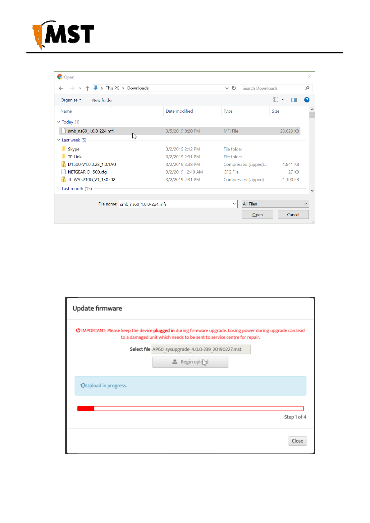
©
A
XON Digital Platform
User Manual
Revision A
3. Click Upload, then OK on subsequent dialogue boxes to confirm. The firmware will upload
to the device.
4. When the firmware has been successfully uplo aded, the UPLOAD SUCCEEDED screen will
appear. The network switch will reboot after 60 seconds.
2019 MST Global CommercialinConfidence
58
Page 69

©
A
XON Digital Platform
User Manual
Revision A
1. Check the device's IP address in the Device Scanner to ensure that it has b een c orr ectly
updated. This address must match the IP address entered in the AeroScout System
Manager for tracking to work.
2. Log back on to the device's web interface and check the STATUS > LOGS screen for any
errors that may need to be addressed.
7.5
Setting Tab
7.5.1 Managing Automatic TFTP Configuration
The Config Management screen is used to configure how the device retrieves its configuration from a
TFTP server on the networ k. For more information on TF TP , see Centralised Configuration Management.
NOTE: These settings only affect TFTP con figu r atio n from an ICA v1.3.1 or earli er,
and 3rd party TFTP servers. If using AP C onfig Te mplates from IC A 1.4.0 o r later,
leave Self check disabled
2019 MST Global CommercialinConfidence
59
Page 70

©
A
XON Digital Platform
User Manual
Revision A
Self-check Settings
To enable automatic configu ration from a TFTP server, tick (enable) the Self check checkbox, enter the
desired Self check interval (default is 300 seconds) and TFTP Server Address, then click the Save.
Change Numbers
The two change numbers shown here are timestamps (formatted as YYYYMMDDhhmmss) showing the
last time the device's settings were updated via TFTP. The Site Change Number refers to genera l site
settings applied to all devices, wher ea s the Device Change Number refers to specific settings applied
to this device.
7.5.2 Configuring SNMP Settings
The SNMP screen contains S imple Netw ork Manage ment Proto col setti ngs . SNM P is a protocol used by
the ICA and 3rd party SNMP browsers to monitor the status of compatible devices on the network. At
present, the ICA only use s this protocol to monito r for Por t Up/Port Dow n errors on AX ON Core and is not
affected by the settings below.
2019 MST Global CommercialinConfidence
60
Page 71

©
A
XON Digital Platform
User Manual
Revision A
The following settings are available, which may affect 3rd party SNMP tools:
Name: The name or ID of the device
Contact: The name of the person to be notified of any alarms
Location: The location of the device
Community String: The group to which the dev ice belongs. Unless otherwise ne cess ary, this is usuall y
left as public.
7.5.3 Setting Up the LAN
The LAN configuration screen is shown in Figure 29: LAN configuration screen.
Figure 29: LAN configuration screen
2019 MST Global CommercialinConfidence
61
Page 72

©
A
w
XON Digital Platform
User Manual
Revision A
To edit LAN settings, cl ick in the sel ected fiel d in the di alog box. LAN se ttings are described in the tabl e
below.
Field Description Recommended Settings
Get LAN IP from
DHCP (Dynamic) or Static IP (Manual)
Default is DHCP. If Static IP is
selected, the following fields must be filled
in.
IP Address
Subnet Mask
Gateway
Primary DNS
Secondary DNS
Local Domain Name
The IP address of the WAC. A different IP address is required for each
Identifies the subnet the IP address
belongs to for the WAC.
The IP address of the default gateway
to be used by the WAC.
The DNS server used by the WAC
hen looking up host names.
The backup DNS server used by the
WAC when looking up host names.
WA C in a network.
The default subnet mask is 255.255.255.0.
Settings are dependent on the site's
network design.
Settings are dependent on the site's DNS
design.
Settings are dependent on the site's DNS
design.
Local domain name for the network. Leave the field blank if you do not wish to
add a domain name.
If the device is left on DHCP, only the following fields are shown. These values will function as above,
only if they are not defined by the DHCP serv er.
2019 MST Global CommercialinConfidence
62
Page 73

©
A
XON Digital Platform
User Manual
Revision A
2019 MST Global CommercialinConfidence
63
Page 74

©
A
7.5.4 Configuring Wireles s R adio
XON Digital Platform
User Manual
Revision A
The Wireless Radio configuration screen configures wireless radio settings as shown in Figure 30:
Wireless radio configurat i on screen .
Figure 30: Wireless radio configuration scre e n
2019 MST Global CommercialinConfidence
64
Page 75

©
A
R
A
r
w
r
A
r
r
XON Digital Platform
User Manual
Revision A
To configure the wirele ss radio:
1. Select the Enable Wireless Radio check box to enable wireless.
2. To change wireless radio settings, edit the required fields. A description and recommended
settings are shown below.
3. Click Save Settings.
Field Description
ecommended Settings
Enable Wireless
Radio
Region
Used to enable or disable the WAC's radio.
Limits available channels to those allowed
by local regulations
Transmission Rate Settings to configure how fast data is
transmitted.
Select the correct region for the site
location.
Leave the default setting as Best
(automatic) for data transmissi on at
the best possible speed.
802.11 Mode
drop-down box to select the 802.11 mode
om mixed 802.11g and 802.11b to 802.11g.
f
If there are 802 .11b wi reless client
devices, leav e the setting at Mi xed.
Select 802.11g for improved
performance if all wireless client
devices are 802.11g capable.
Super AG Mode See section below. See section below.
Transmit Pow er
Used to control the power delivered via the
ireless transmitter.
Transmit Antenna Defines the antenna to be used for
High - Only drop to Medium or Low if
the signal is inter fering with other
devices.
Main
transmission of wireless frames. The options
are:
Main: The MAIN antenna w ill always be used
fo
transmission .
ux: The AUX antenna will always be used
fo
transmission .
Diversity: The radio will determine the best
antenna to use for transmission based on
the signal strength of recently received
f
ames from both antennas.
2019 MST Global CommercialinConfidence
65
Page 76

©
A
R
r
A
r
r
M
D
Field Description
XON Digital Platform
User Manual
Revision A
ecommended Settings
Receive Antenna Defines the antenna to be used for the
reception of wireless frames. The options
are:
ain: if a single antenna is fitted.
iversity: if antennas are fitted to
both of the radio's ports.
Main: The MAIN antenna w ill always be used
fo
reception.
ux: The AUX antenna will always be used
fo
reception.
Diversity: Both antennas will always be used
fo
reception and the received frame with the
best signal strength will be used.
IMPORTANT: Ensure that the physical connection of antennas is consistent with the
transmit and receive antenna settings. Failure to do so will give poor Wi-Fi
performance and reduced tracking accuracy.
Channels
It is recommended that WACs in proximity of each other have different wireless channels (for example,
channels 1, 6 and 11). This minimises signal overlap and the possibility of interference.
2019 MST Global CommercialinConfidence
66
Page 77

©
A
R
r
A
r
V
w
Advanced Wireless Settings
Field Description
XON Digital Platform
User Manual
Revision A
ecommended Settings
Fragmentation
Threshold
Maximum frame size that can be sent witho ut
f
agmentation.
RTS threshold Determines what size data packet the low level
Beacon Period
DTIM interval
RF protocol issues to an RTS packet.
The amount of time between beacon
transmissions.
DTIM is a countdown i nforming clients of the
next window for listeni ng to broadca st and
multicast messa ges. Wireless client s de tect the
beacons and awake n on the DTIM inter val to
ecei ve the broa dcast and multicast messages.
alid settin gs are between 1 and 255.
Burst Time The time in microsecond s which will be used to
send data without stopping. Note that o ther
ireless cards in that network will not be able to
transmit data for this period.
802.11d enable Wireless specification where configuration
occurs at a MAC layer level to comply with
country or district rule s.
Default setting is at the
maximum size of 2346 and is
recommended for most
environments.
Default setting is 2346.
Default setting is 100ms.
The recommended DTIM
interval is 1.
Default 3000μs (0.3s)
802.11d is not enabled by
default.
7.5.5 Configuring Wireles s N etw orks
A WAC can have up to four wireless SSIDs with different performance and security settings. Each can
be mapped to different VLANs. The configura ti on scree n is shown in Figure 31: Wireless Networks
configuration screen.
2019 MST Global CommercialinConfidence
67
Page 78

©
A
R
v
r
W
W
v
W
w
XON Digital Platform
User Manual
Revision A
Figure 31: Wireless Networks configuration screen
Wireless network parameters are described in the table below.
Field Description
Enable Enables or disables the wireless network. Click on the Enable check box to
ecommended Settings
enable the wireless network.
SSID
The Wireless Network Name network that will be
isible to client devices.
Security Mode Four security modes exist:
None: No wireless authentication is required, and
affic is not encrypted.
t
PA2 Personal: provides a higher level of
security and does not use a centralised
authentication serv er.
PA 2 Enterprise: as per WPA Personal but a
RADIUS authentication server is used.
(WPA Personal and WPA Enterprise are older
ersions of the standard and less secure)
Enter a network name that relates
closely to its function. For
example, "MST-VOICE".
PA2-Personal is
recommended. Selecting the
ireless security mode will display
configuration options .
2019 MST Global CommercialinConfidence
68
Page 79

©
A
XON Digital Platform
User Manual
Revision A
Note: After a unit is reset to factory defaults, it will have a single wireless network on channel 6 with
the name "AP------" (the last six digits of the unit's MAC address), WPA2-AES security enabled
and the password "minesite".
NOTE: After a unit is reset to factory defaults, it will have a single wirel ess network on
channel 6 wi th the name "AP------" (the las t six digits of the unit's M AC address), WPA 2AES security enable and the password "minesite".
Configuring WPA Settings
WP A provides a higher level of security . WPA-Personal and WPA-Enter prise are variants of Wi-Fi
Protected Access (WPA). WPA-Enterprise requires an external RADIUS server.
To configure WPA setti n gs :
1. Select the WPA mode from the drop-down box.
2. Select the Cipher Type from the drop-down box. By default, it is set at AES.
3. Enter the Pre-Shared Key in the supplied field (applicable to WP A Personal securi ty mode).
The key must be at least 8 alphanumeric characters in length.
4. Enter Network Key Rotation Interval in the supplied field. By default, it is 600 seconds.
This is the amount of time before the group key (used for broadcast and multicast data
encryption) is changed.
5. Click Save Settings
Configuring WEP Security Setting s
7.5.6 Configuring EAP (Extensible Authentication Pro tocol)
The Wireless EAP configuration screen is used to configure wi reless authentication b y a RADIUS server
(as used by WP A Enterprise). The configuration scr een is shown in Figure 32: Wireless EAP configuration
Figure 32: Wireless EAP configuration
2019 MST Global CommercialinConfidence
69
Page 80

©
A
A
A
r
r
A
XON Digital Platform
User Manual
Revision A
To configure wireless EAP , clic k on the drop-dow n box es in the supplied fiel d s. Cli ck Save Settings to
save settings. A description of the fields and settings are described in the table below.
Field Description Recommended Settings
uthentication Timeout
mount of time in minute s before a
client device is required to
Setting is at 120 minutes by
default.
e-authenticate.
RADIUS server IP A ddress
IP address of the authentication
se
ver.
RADIUS server Port Port number used by the access
This is specific to each site.
By default the port number is 1812.
point to connect to the
authentication server.
RADIUS server Shared Secret Password used by the access point
to access the RADIUS server.
MAC Address Authentication
ccess to the RADIUS server by
confirmation of the clien t device's
MAC address.
Password that matches with the
authentication server.
If selected, the user must always
use the same device when
connecting to the wireless network.
A second RADIUS serv er can be confi gured if the primary se rver is not avai lable or not respon ding. This
can be configured by clicking on the Advanced button.
7.5.7 Configuring Asset Tracking and Location Based Services
The Tracking configuration screen establishes w here AeroScou t ta g reports are sent as shown in
Figure 33: Tracking configuration screen. A network device can communicate with an AeroScout
Positioning Engine and / or a MST Tracker Engine. Configuration of the Access Point is not required
when communicating w ith an AeroS cout Positi oning Engine as the devi ce configu ration is performe d vi a
AeroScout server tools.
2019 MST Global CommercialinConfidence
70
Page 81

©
A
A
XON Digital Platform
User Manual
Revision A
Figure 33: Tracking configuration screen
If the Access Point is sending tag reports to an MS T Tracker En gine , the Tra cker Engine's IP address
must be entered into each Access Point.
There are four sections on the Tracking configuration screen:
Enable
Check Enable Wi-Fi Tracking to view other settings.
RSSI Lower Thresholds
These settings are used to con trol w hat loca tion r eports are sen t to the P o siti oni ng Engi ne. I f a Wi-Fi ta g
or mobile unit repo rt is receiv ed with an RSSI below the relevant thresh old, it is not sen t to the Positio ning
Engine (whether it is an AeroScout Positioning Engine or MST Tracker Engine). The default threshold is
-95 dBm, but this can be raised or lowered according to specific site conditions and requirements.
Tracker Engine List
This section is used to configure the M ST Trac ker Engi ne (s ) that the acce ss point will send information
to. The available settings are listed b e low. N ote that data can be passed to up to 2 MST Tracker Engine
instances.
Field Description Recommended Settings
Enable Indicates whether the Tracker Engine will be sent
data.
On or Off.
IP Address The IP address of the MST Tracker Engine. Specific to each site.
Port The UDP port that the Tracke r Engine listens for
messages on.
Status Update Interval The period that status reports wil l be sent from the
Default is 1142.
Default is 15 seconds.
Access Point to the Tracker Engine. These sta tus
reports are used by the Tracker Engine to
eroScout Tags
Enabled
determine if the Access Point is up or down.
Indicates which devices will be tracked by this
Access Point.
These options are enabled by
default.
MST Wi-Fi Tags
Enabled
Mobile Units Enabled
2019 MST Global CommercialinConfidence
71
Page 82

©
A
XON Digital Platform
User Manual
Revision A
Advanced Settings
Drop non-exciter tag reports - If enabled, the Access Point will only send tag reports when the tag is in
an AeroScout Exciter field.
This setting applies to ta g reports that are sent to AeroScout Positioni ng Engines and MST Trac ker Engines.
7.5.8 Configuring Ethernet Switch Ports
The WAC in slot 1 (located on the left side of AXON Core) is used for configuration and man agement of
the switch processors in the network switch. It enables the ports on the switch and the 48V rail for the
Power over Ethernet (PoE) supply to be configured, as shown in Figure 34: Switch configuration screen.
Figure 34: Switch configuration screen
The Switch ports have the follow i ng configura ti o n opti on s:
Field Description Recommended Settings
Name Used to provide a convenient name for the
port. It is often used to name the device
2019 MST Global CommercialinConfidence
Naming is specific to eac h device.
72
Page 83

©
A
connected to it. For example, "Level 68
camera".
Enabled Enables or disables the port. On or Off.
XON Digital Platform
User Manual
Revision A
Speed & Duplex Ports 5 thru 8 allow the speed and duplex to be
controlled.
Auto is usually the best setting.
However, some devices require
Speed & Duplex to be h ard coded
due to poor Auto-negotiation
implementations.
2019 MST Global CommercialinConfidence
73
Page 84

©
A
XON Digital Platform
User Manual
Revision A
7.5.9 Defining VLANs
The VLAN LIST screen di splay s VLANs and the pr iority that w ill be assigne d to traffi c on each VLAN .
Figure 36: VLAN list configuration screen
Up to 8 VLANs can be defined with the following parameters:
Enable: Check box to enable the VLAN.
ID: VLAN ID number that is tagged in fra m es sent th rough trunk ports .
Name: VLAN name. It should be named to simplify administration.
Priority: Priority ranges from 0-7 (7 being the hi gh est p riority) that is assigned to frames on this
VLAN.
NOTE: The first VLAN (Infrastructure) cannot be disabled, because the man agement
CPU is always on this VLAN.
By default, VLANs are pre-defined with recommended IDs and priorities. This is based on commonly
used applications in mines. Once the VLANs are defined, they can be saved by clicking on the Save
Settings button.
After the VLANs have been defined, they can be assigned to the wireless networks and switch ports
(Network Switch only) on the VLAN PORT MAP screen.
2019 MST Global CommercialinConfidence
74
Page 85

©
A
XON Digital Platform
User Manual
Revision A
7.5.10 Configuring the VLAN Port Map
The VLAN Port Map screen assigns the VLAN (s) to each physical switch port, and each wireless ne twork.
The screen is shown in Figure 37: VLAN Port Map screen.
Physical switch ports can be assigned as Trunk or Access ports. Wireless networks always act as
Access ports on the selected VLAN.
Figure 37: VLAN Port Map screen
2019 MST Global CommercialinConfidence
75
Page 86

©
A
XON Digital Platform
User Manual
Revision A
Chapter 8: Centralised Configuration Management
Topics:
Devise Management Overview
TFTP Server Overview
TFTP Parameters
Centralised configuratio n man a ge ment is an alte r na tive configuration method to the web interface. It
uses Trivial File Transfer Proto col ( TFTP ) where de vices read and apply configuration files fro m a TFTP
server. It is a faster way to configure a large number of network switches, reducing the potential for
human error.
To take advantage of TFTP configuration:
For networ ks with an ICA v1.4 .0 or higher , AP settings can be man aged from the ICA Administration
console. A customisable Site Default template is incl uded at installation, and further templates can b e
copi ed from it and modified s epa ratel y. Ad ditio nally , indivi dual APs can have specific settings overridden
via the Administration Console.
In this case, the ICA will push configuration cha nges to the APs, and no local setup is required.
2019 MST Global CommercialinConfidence
76
Page 87

©
A
XON Digital Platform
User Manual
Revision A
8.1
Device Management Overview
The ICA Administration Console (v1.4.0 and later) supports the creation of Access Point configuration
templates. A Site Default template is created a t install ation and applied to al l mana ged devices. New
templates can be copied from the Site Default and applied to sel ected devices, and further override s
can also be applied to individual devices.
Some familiarity with the ICA Administration Console is assumed here. For more information, see the
ICA Administration Console User Manual available from MST.
There are three editors in the ICA Administration Console with relevant settings:
Configuration > Site C onfiguration
Configuration > AP Config Templates
Devices > Access Poi nts
8.1.1 Site Configuration
This editor contains the o ption to Set ne w Access Points as Managed - If checked, all newly discovered
Access Points wi ll be configu red accordi ng to the Site De fault template by the ICA. If disabled , new APs
must either have their management settings configured in the Devices > Access Points editor, or be
configured manually.
2019 MST Global CommercialinConfidence
77
Page 88

©
A
XON Digital Platform
User Manual
Revision A
8.1.2 AP Config Templates
The ICA is installed with one AP Template: Site Defaults. This is a special AP Temp l at e whic h defines
the settings that new APs will automatically pick up if Set new Access Points as Managed is ticked in
the Site Configuration editor. This template cannot be deleted, but new templates can be copied from it
and modified separately.
NOTE: Once a template is applied to an AP, any manual changes made to settings listed
in the template will be reverted automatically to the template default. Settings that are not
defined by the template can be changed freely.
New templates are created b y copying an existi ng template (initially the only o ne to copy is Site Defaults).
A copied template will start with the same para m eters as the ori gi nal , but they are not lin ked, so further
changes to one will not affect the other . To create a new template, select another template from the list
and click the Copy button. To delete a template, click the Remove button.
AP Config Template Details
This section contains the details for each te mplate:
System ID is an automatically assigned identifier used by the ICA.
Name - A name or description for the template.
Edit Parameters - Individual parameters can be sel ected and modi fied, or i gnored, for ea ch te mplate
by clicking this link to open the Parameters dialogue box (See Edit Parameters section below ).
2019 MST Global CommercialinConfidence
78
Page 89

©
A
XON Digital Platform
User Manual
Revision A
Editing Parameters
In the Parameters dialog box , search for the desired parameter by typing all or part of any of the displa yed
column values :
Managed: To manage a parameter, tick the checkbox in this column. Fixed entries cannot be disabled
or changed, while required entries can be edited but not disabled. U nmarked entries can be di sabled
by unticking the checkbox.
Parameter Name: For more informatio n on parameters that affe ct a specific AP model on the network,
see the TFTP Paramet ers section of the user manual for that model.
Parameter Value: To edit a parame ter, cli ck on th e parameter val ue and either en ter a new v alue (e.g.
names and IP addresses) or select a n ew value from the dropdown menu (e. g. ENABLED / DISABLED).
When all required changes have been made, click OK to cl ose the dialog box. The Managed status of
all available parameters can be changed at once using the Manage All and Manage None checkboxes
below the list.
2019 MST Global CommercialinConfidence
79
Page 90

©
A
XON Digital Platform
User Manual
Revision A
8.1.3 Access Point
Access Points (APs) become visible to the ICA after the map containing them is first synchronised from
AeroScout. Once visible, APs are automa ti cal l y added to the List of Access Points
2019 MST Global CommercialinConfidence
80
Page 91

©
A
XON Digital Platform
User Manual
Revision A
List of Access Points
The Managed column shows CURRENT for managed devices with up-to-date settings, or PENDING for
devices awaiting newly updated settings.
To edit an existing entry: Click on that ent ry , fill in the rel evant fields on the right, then click the Save
button or press Ctrl+S:
Manage Configuration
To have an AP's configuration mana ged by the IC A, tic k the Manage Configuration checkbox, and
select the correct template fro m the d ropdown menu.
Last Change shows the time of the last change to the AP's configurati on management settin gs if known,
and PENDING if new settings are waiting to be sent.
IMPORTANT: If any cha nges are made to a managed AP 's settings v ia the w eb
interface that conflict with the selected template or overri dden parameters (see below ),
those changes will be automatically rev erted by the ICA. Setting s that are no t defined
in the template will be ignored.
2019 MST Global CommercialinConfidence
81
Page 92

©
A
XON Digital Platform
User Manual
Revision A
Editing Overridden Parameters
Individual parameters specified in a template can be modified for the selected AP. To modify any
parameters, click Edit Ov erridd en Parameters.
In the Parameters dialog box , search for the desired parameter by typing all or part of any of the displa yed
column values :
Overridden: T o override a parameter, tick the checkbox in this column. Fixed entries are enabled
by default and cannot be disabled or changed. Required entries are not enabled by default; once
ticked, they can be edited b ut not disabled. Unmarked entries can be disabl ed by unticking the chec kbox.
Parameter Name: For more information on para meters, see the TFTP Parameters section of the
user manual for the selected access point.
Parameter Value: To edit a pa rameter, clic k on the parame ter value and eithe r enter a new v alue (e.g.
names and IP addresses) or select a n ew value from the dropdown menu (e. g. ENABLED / DISABLED).
2019 MST Global CommercialinConfidence
82
Page 93

©
A
XON Digital Platform
User Manual
Revision A
When all required changes have been made, click OK to cl ose the dialog box. The override status of all
available parameters can be changed at once using the Override All and Override None checkboxes
below the list.
8.2
TFTP Server Overview
Centralised configuration management using ICA v1.3.1 or earlier, or a 3rd party TFTP server, involves
the following steps:
1. Configure a TFTP server on the network. The ICA is precon figured for this purp ose.
Configuring a 3rd party server is outside of the scope of this document.
2. Define a site configuration file that contain g lobal settings to all netw ork dev ices on the site.
3. Define device configuration files that contai n specific settings for each device, which ov erride
global settings.
4. Apply the configuration files to each device and reboot.
Network devices read and apply the configuration files from the TFTP server as shown below.
2019 MST Global CommercialinConfidence
83
Page 94

©
A
XON Digital Platform
User Manual
Revision A
Figure 39: Centralised co nfiguration management
8.2.1 Editing Site Configuration Files
Site configuration files contain common settings for all devices in a network. The site configuration file
has the naming convention ap_site_settings.conf. This file is retrieved by devices using TFTP.
NOTE: The same site configuration file can be used to configure netw ork swi t ch
units and WAP s in a network. When the site configuration file is applied to WAP s, all
The site configuration file can be opened on a PC and edited using a tex t edi tor. Paramete rs are
changed by modifying the text and saving the file. A description of the editable parameters are covered
in the following sections.
switch port settin gs are ignored by the WAP.
2019 MST Global CommercialinConfidence
84
Page 95

©
A
XON Digital Platform
User Manual
Revision A
To edit a site configuration file:
1. Open a text file editor on your PC.
2. Locate and open the site configuration file ap_site_settings.conf. This is usually stored in
the file directory folder of the TFTP server.
1. Edit the parameters as required.
2. Save the site con fi guratio n file in the directory fold er o f the TF TP serv er.
8.2.2 Editing Device Configuration Files
Device configuration files con tai n set ti ng s specific to each WAC in the netw or k devi ce. A dev i ce
configuration file is created for each WAC. Device configuration files follow the naming convention
ap_MACaddress.conf where MACaddress is the MAC address of the WAC. A device will recognise
and apply the device configuration file based on a comparison of the MAC address in the file name.
Note that any parame ter from the site confi guration file can overri de parameters in a devi ce configuration
file. However, it is recommended tha t only the set ti ngs that ar e di fferen t be entered into the device
configuration file in order to make maintenance easi er.
A device configuration file configures individual settings for each device as shown below. The device
configuration file can be edited usin g a text editor such as Wordpad or Notepad. The example below
includes settings that are comm onl y over-ridden. All other settings are inh erited from the global site
configuration file. Comments are prefixed with a hash symbol (#) and are ignored by the device. These
are not necessary for configuration but may be included for convenience.
# Mine Site Technologies Netw ork and power distribution module ConfigFile
# ======
# System
#
system.hostname=AP57R2 system.location=Mine Location 16
# Wireless Radio Configuration
# ============================
2019 MST Global CommercialinConfidence
85
Page 96

©
A
w
0
1
XON Digital Platform
User Manual
Revision A
The parameters shown in the example device configuration file are described in the following table.
Section Parameter Description Settings
System system.hostname
System system.location
Wireless Radio
Configuration
Power over
Ethernet
ireless.radio .1.chan nel Wi-Fi channel that
switch.poe.enabled Enabling PoE
To edit a device configuration file:
3. Open a text file editor on your PC.
4. Locate and open the device configuration file ap_MACaddress_settings.conf. This is usually
stored in the file directory folder of the TFTP server.
5. Edit the parameters as required.
6. In the directory folder of the TFTP server, save the file using the naming
ap_MACaddress_settings.conf, where MACaddress is the MAC address of the WAC card to
configure.
Network switch
name.
Location name of
the network switch.
the WAC will
operate on.
supply on the
network switch.
Each device should have a unique name
identifier.
It is recommended the location name is
relevant to the physical locati on of the
device.
It is recommended WAC s in prox imity of
each other have assigned channels 1, 6
and 11. This minimises signal overlap and
interference.
0 = Disabled, 1 = Enabled
NOTE: This setting is not applicable to
WAPs and will be ignored when the file is
applied to a WAP.
8.3 TFTP Parameters
Below is a list of configurable parameters for AXON Core, classified by type.
Network
Common LAN settings to all devices on a network as shown below.
Field Description
network.1.addr.mode
network.1.addr.static The IP address of the device, if Static.
network.1.netmask Identifies the subnet the IP address belon gs to fo r the dev ice.
2019 MST Global CommercialinConfidence
: Static - fixed IP address configured manua l ly on the device
: DHCP - IP address assigned automatically
86
Page 97

©
A
t
0
1
t
t
A
XON Digital Platform
User Manual
Revision A
network.1.local_domain_name T he domain name of the local network.
Field Description
network.1.gateway The IP address of the default gateway.
network.1.dns.primary The DNS server to be used when looking up host names.
network.1.dns.secondary The bac kup DNS server to be used when l ooking up host names.
Configuration Management
These settings are only required for 3rd party TFTP servers or ICA v1.3.1 and earlier.
Field Description
ftp.self_check_enabled
: Disabled
: Enabled - device will check the TFTP server for changes at startup
ftp.self_check_interval
ftp.server_address
and every "tftp.self_check_interval" minutes
The number of seconds elapsed be fore checking for new TFTP
settings. If zero, do not perform regular checks.
The TFTP server address to use. If blank, and in DHCP mode, use
the address supplied by DHCP.
System
Network names, contact details and passwords can be edited in the system section of the configuration
file as shown below.
Field Description
system.contact Contact name for the ne twork devices.
system.location Location of the network devices.
system.password.admin
dministrator password. The de fault pa ssword is "admin".
system.password.user User password. The default password is "user".
system.hostname
2019 MST Global CommercialinConfidence
Device hostname as displayed in the Device Scanner, should be
unique for each device.
87
Page 98

©
A
0
1
0
1
A
0
1
2
3
4
5
6
7
0
1
XON Digital Platform
User Manual
Revision A
NTP (Network Time Protocol)
The Time section shown below defines NTP (Network Time Protocol) server settings for the network
switch.
Field Description
time.ntp.enabled
: Disabled
: Enabled - dev ice will synch ronise time with an NTP server (requires
network or internet access to an NTP server).
time.ntp.server1 Hostname or IP address o f NTP serv er. For ex ample
time.windows.net.
Logging
System message logging settings.
Field Description
syslog.enabled
: Disabled
: Enabled
syslog.server_address The hostname or IP address of the syslog server
syslog.level
ll messages from 0 to the selected number will be logged.
: Emergency
: Alert
: Critical
: Error
: Warning
: Notice
: Informational
: Debug
SNMP
Simple Network Management Protocol settings. At present, the ICA only uses this protocol to monitor for
Port Up/Port Down errors on AXON Core, and is not affected by the settin gs bel ow, adjust onl y if required
for 3rd party monitoring software.
Field Description
snmp.enabled
: Disabled
: Enabled
2019 MST Global CommercialinConfidence
88
Page 99

©
A
0
1
0
1
A
0
1
0
1
XON Digital Platform
User Manual
Revision A
Field Description
snmp.community.read The SNMP community string for rea ds. Unless otherwise
necessa r y, th is is usually left as public.
snmp.trap.destination.1 T he hostname or IP address of the primary SNMP trap.
snmp.trap.destination.2 The hostname or IP address of the secondary SNMP trap.
Asset Tracking and Location Servers
This section configures asset tra c king and l ocati on servers, consisting of AeroScout Posi ti oni ng Engi nes
or MST Tracker Engines. This is where AeroScout tag and Wi-Fi client device information is sent.
Configuration is not required when communicating with an AeroScout positioning engine.
Field Description
tracking.enabled
: Disabled
: Enabled
tracking.aeroscout.enabled Tracking of AeroScout tags.
: Disabled
: Enabled
tracking.aeroscout.rogue_ap_dete
ction
Reports non-compatibl e access point s on the netw ork to the
eroScout Engine.
: Disabled
: Enabled
tracking.aeroscout.excited_tags_
only
Only sends tracking informatio n for dete cted tags within range of
an exciter.
: Disabled
: Enabled
tracking.rssi_threshold.tag
tracking.rssi_threshold.mu
By default it is set at -95. Only tag repor ts higher than this si gnal
strength threshold will be sent to the positioning engines.
By default it is set at -95. The default value should not be
changed without understanding the implications. Only Wi-Fi
client frames higher than this si gnal st rength threshold will be
sent to the positioning engines.
These settings configure up to two MST Tracker Engines that the access poi nt wi ll send informa ti on to .
The "x" in each parameter is replaced by the tracking engine number.
2019 MST Global CommercialinConfidence
89
Page 100

©
A
v
v
v
v
v
Field Description
XON Digital Platform
User Manual
Revision A
tracking.tracker.x.enabled
tracking.tracker.x.excited_tags_only
0: Disabled
1: Enabled
Only sends tracking informatio n for dete cted tags within
range of an exciter.
0: Disabled
1: Enabled
tracking.tracker.x.server_address The IP address of the MST Tracking Engine.
tracking.tracker.x.server_port UDP port to be used by messages sent to the MST Tracker
Engine. Default 1142.
tracking.tracker.x.status_reporting_interval The period in seconds b etween status reports being sent to
the MST Tracker Engine. These status reports are used to
determine Access point availability.
VLAN Configuration
The VLANs section de fines VLANs for the devi ces as shown bel ow. For la rge networks it is reco mmended
that VLAN settings are applied to all network devices consistently by using centralised configuration
management. Up to 8 VLANs can be defined, the "x" in each address is replaced by the VLAN number 1-
8. By default, the site configu ratio n fi l e has some VLANs predefined based on commonly used
applications. VLAN parameters are described in the table below.
Field Description
lan.enabled
lan.entry.x.enabled
lan.entry.x.id
0: Disabled
1: Enabled
0: Disabled
1: Enabled
The VLAN ID that will be tagged to frames sent to trun k ports
from VLAN x.
lan.entry.x.priority Priority from 0-7 (with 7 being the highest) that is assigned to
frames on VLAN x.
lan.entry.x.name The administrative name for VLAN x.
NOTE: The Infrastructure VLAN cannot be edited or disabled because the management
CPU is on this VLAN.
2019 MST Global CommercialinConfidence
90
 Loading...