

Page 1
TM
Service & Troubleshooting
M&S Systems is committed to producing high
quality audio products for the home. If you have
any questions or problems with the speaker
systems or the system is not operating properly,
contact your WaveGuide installer or call M&S
Systems at (800) 366-9422.
TM
In-Wall & Ceiling Speakers
2861 Congressman Lane
Dallas, TX 75220
800.877.6631
www.mssystems.com
Owner’s Manual
Part Numbers
WG100C WG100W
WG150C WG150W
115986
Page 2
TM
TM
Introduction
WaveGuide ceiling and in-wall speakers are
designed to provide clear, sharply-focused audio
reproduction while remaining unobtrusive in the
background. These speakers bring out the best in any
home theater or whole-house stereo system. These
products also offer many features, including:
• 1” Asymmetrical Aluminum Dome Tweeter
• Slide switches for bass and treble control
(+/-3dB)
• Cam-lock mounting system with isolated
rubber pads to reduce vibration
• Kevlar cone for low distortion and smooth
response
• Molded in IR lens that allows installation of an
infra-red receiver through the speaker baffle
• Gasket around the baffle to provide an
acoustic seal
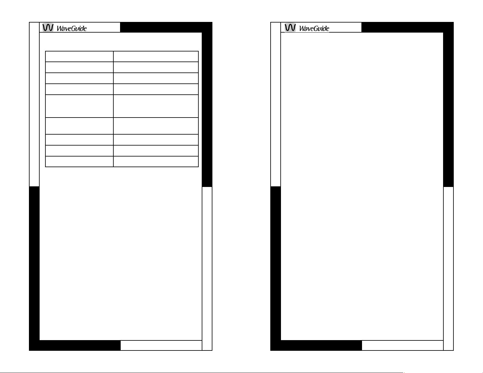
Description
Ceiling Speakers
WG100C
Frequency Response 50Hz to 20kHz (+/-3db)
Maximum Power Rating 100 Watts
Impedance Rating 8-Ohms
Overall Speaker Dimension 9” Diameter
Specifications 6” Kevlar cone woofer;
Mounting Dimension w/o
Mounting Ring
Mounting Ring Dimension 8 3/16” Diameter
Grille Aluminum
Color White
(Sold in Pairs)
1” asymmetrical aluminum dome
tweeter
7 1/2” Diameter
WARRANTY
M&S Systems™ Limited 10-Year Warranty for WaveGuide™
Speakers and AirVac™ Gold Power Units
M&S Systems offers a 10-Year Warranty on our WaveGuide™
speakers and AirVac™ Gold power units. This warranty is identical
to the M&S Systems™ 2-Year Warranty, with the exception that this
warranty covers the WaveGuide™ speakers and AirVac™ Gold
power units for 10 years instead of 2. The M&S Systems™ 10-Year
Warranty applies ONLY to the WaveGuide™ speakers and
AirVac™ Gold power units and to no other M&S Systems™, M&S™
8- ohm or AirVac™ products.
M&S Systems Limited 2-Year Warranty
M&S Systems warrants its products to be free of defects for 2 years.
Except for the WaveGuide™ Speakers and AirVac™ Gold power
units (See above). The warranty period begins on either (a) the date
of purchase or installation date of this product or (b) the date of
closing on a new residence in which this product was originally
installed.
The warranty extends to the original user of the product and to each
subsequent owner of the product during the term of the warranty.
M&S™ will repair or replace, at its option, parts and materials at no
charge. Parts supplied under this warranty may be new or rebuilt at
the option of M&S Systems™.
If during the warranty period the product appears to have a defect,
please call our toll free service number (800-366-9422) prior to
dismantling. Dismantling the product prior to calling our service
number may void the warranty. Before returning any product to M&S
Systems™, obtain a Return Authorization Number (RAN) from our
service department. M&S Systems will return the repaired
product freight prepaid within the continental United States. ANY
PRODUCT RETURNED TO M&S SYSTEMS WITHOUT A RAN
NUMBER WILL BE REFUSED.
This limited warranty is in lieu of any other warranties, express or
implied, including any implied warranty of merchantability or fitness
for a particular purpose or otherwise, and of any other obligations or
liability on the seller’s part. This limited warranty does not cover
damage caused by improper installation, acts of God, criminal acts,
the violation of applicable building or electrical codes or the use of
non-M&S wire, cable (excluding CAT5 and RG-6) or wall housings.
Under no circumstances shall M&S Systems™ be liable for
consequential, incidental or special damages arising in connection
with use, or inability to use this product. In no event shall M&S
Systems™ liability hereunder exceed the cost of the product
covered hereby. No person is authorized to assume for us or
obligate us for any other liability in connection with the sale of this
product. Some states do not allow the exclusion or limitation of
consequential, incidental or special damages, so the above
limitation or exclusion may not apply to you. This limited warranty
gives you specific legal rights, and you may also have other rights,
which vary from state to state.
Page 2
Page 2
Page 23
Page 3
TM
TM
red wire in the red terminal and the black wire in
the black terminal. See figure 10. Make sure that
none of the strands from the black and red wires
are touching each other. This can create a short
circuit that can damage your electronics. Mount
the baffle to the frame using the 6 screws
provided. Do not over tighten the mounting
screws.
Step 12. After the speaker is mounted,
adjustments to the swivel tweeter (small speaker)
can be made by either directing the sound
visually or by using a musical source to
determine the best sound coverage for the
listening area. To position the tweeter, press at
the outside edge of the tweeter housing (DO
NOT PRESS ON THE CONE DIRECTLY).
Note the crease in the asymmetrical tweeter
provides the highest directional response in this
direction. See figure 11 on page 14.
If you require to disperse the sound in a 360degree pattern you must position the line in the
tweeter in a horizontal position. See figure 12 on
page 15.
The combination of switch settings allow you to
boost and cut bass and treble +/-3dB. Adjust the
speaker level to accommodate for room
acoustics. See figure 13 on page 15.
Step 13. Divide each adhesive bead strip in half.
(Adhesive bead strips are in the clear self-closing
bag). Place strips on the edge of the grille as
shown in figure 14 on page 15. Reinstall the grille
on the speaker.
Step 14. Adhere the WaveGuide logo to the grille
with the pressure sensitive tape.
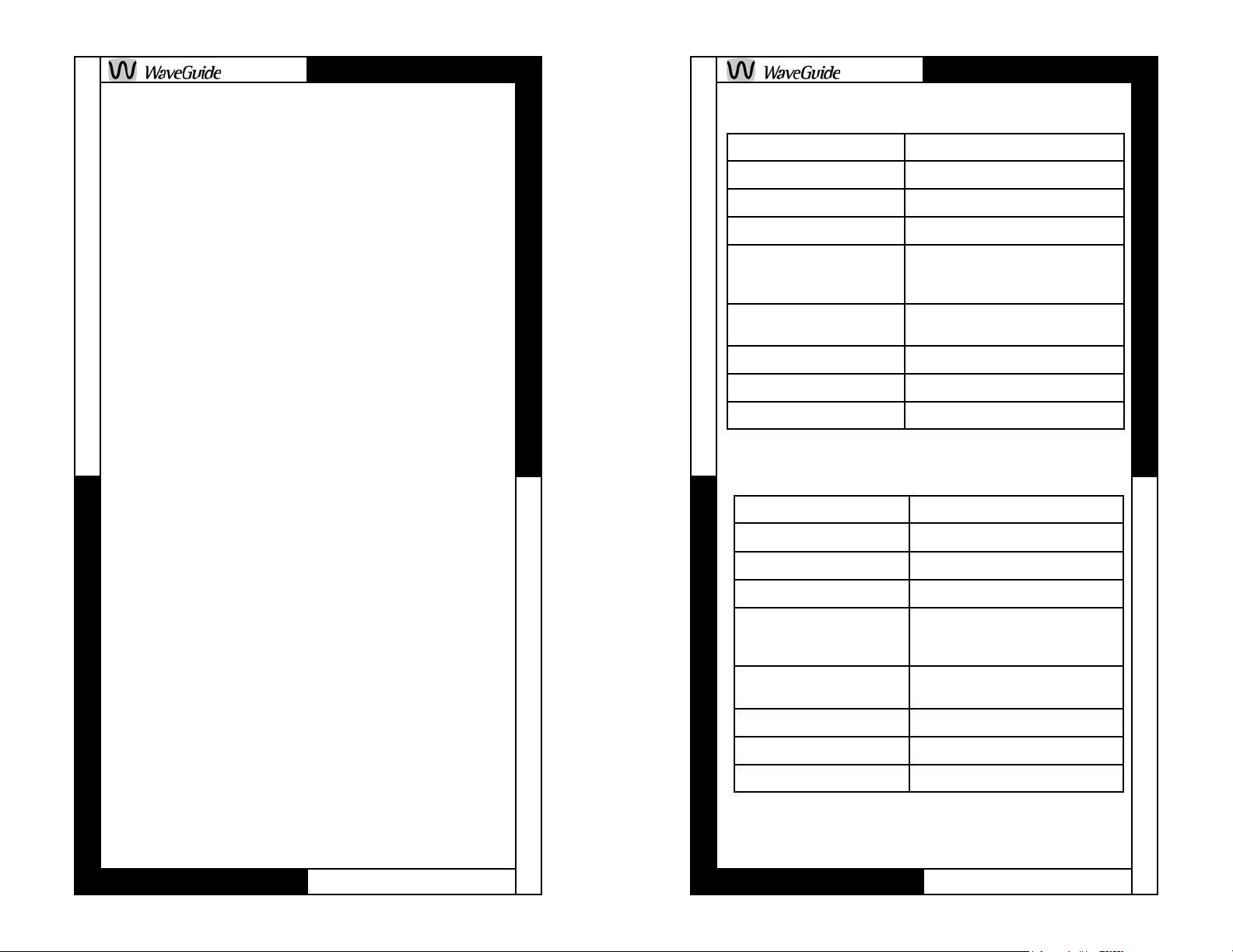
WG150C
Frequency Response 35Hz to 20kHz (+/-3db)
Maximum Power Rating 150 Watts
Impedance Rating 8-Ohms
Overall Dimensions 10 7/8” Diameter
Specifications 8” Kevlar cone woofer;
1” asymmetrical aluminum dome
tweeter
Mounting Dimension w/o
Mounting Ring
Mounting Ring Dimension 10 1/16” Diameter
Grille Aluminum
Color White
In-Wall Speakers
9 5/8” Diameter
(Sold in Pairs)
WG100W
Frequency Response 50Hz to 20kHz (+/-3db)
Maximum Power Rating 100 Watts
Impedance Rating 8-Ohms
Overall Dimensions 9” W x 12 5/16” H
Specifications 6” Kevlar cone woofer;
1” asymmetrical aluminum dome
tweeter
Mounting Dimension w/o
Mounting Ring
Mounting Ring Dimension 7 15/16” W x 11” H
Grille Aluminum
Color White
7 1/2” W x 10 13/16” H
Page 22
Page 3
Page 3
Page 4
TM
TM
WG150W
Frequency Response 35Hz to 20kHz (+/-3db)
Maximum Power Rating 150 Watts
Impedance Rating 8-Ohms
Overall Dimensions 10 1/4” W x 14 15/16” H
Specifications 8” Kevlar cone woofer;
1” asymmetrical aluminum dome
tweeter
Mounting Dimensions w/o
ring
Mounting Ring Dimension 9 3/16” W x 13 3/16” H
Grille Aluminum
Color White
8 11/16” W x12 3/4” H
Unpacking Your Speakers
Before you unpack your speakers, be extra
careful not to touch the cone and tweeter
materials. After carefully unpacking your
speakers, the carton and the packing material
should be saved for possible use later. If any
speaker appears to be damaged, do not attempt
to repair or to connect the unit to the amplifier.
Repack the speaker and notify your distributor or
M&S Systems for replacement or repair.
Speaker Location
Ceiling Installation
Careful consideration must be given to the
speaker location to realize the full frequency
range. Ceiling speakers should be spaced 6 to 8
feet (6 feet for 8-foot ceilings and 8 feet for 10-
tearing wallpaper. Then use a drywall or keyhole
saw to cut along the scored line. Make sure that
you do not cut the hole larger than the outline.
Step 7. Be sure to clear any insulation material
from the speaker back.
Step 8. After you have determined the speaker
locations secure a 16 gauge 2 conductor cable to
the stud using an insulated staple. Leave at least
18 inches of additional cable for connection
during final speaker installation. Run the other
end of the speaker cable to the audio source.
Step 9. Prepare the speaker wiring by stripping
off approximately 3 inches of the outer jacket
(care should be taken so the insulation on the
wires inside the jacket are not damaged) also
strip approximately 3/8 inch off the ends of the
two inside conductors. Twist the ends of the
stranded cable so the wires are tight.
Step 10. Follow the instructions included with the
volume control and amplifier.
Step 11. You are now ready to install the frame.
Remove the paint mask. Be careful not to touch
the speaker cones and tweeters when
removing the paint mask in order to prevent
any damage. Remove the baffle from the frame
and fasten the frame to the drywall. Index the
mounting tabs to make sure that all tabs will clear
the opening. Insert the frame in the wall and
tighten the tabs with the screws on the front of
the baffle. Attach the speaker cable to the
speaker by pressing down on the red (+) or black
(-) gold-plated push terminals and inserting the
Page 4
Page 21
Page 5
TM
TM
sound. When the sound is deeper and more
hollow sounding, you are between studs.
When the sound is sharper and more flat
sounding, you are close or over a stud.
• Identify studs by the position of electrical
outlets or switches. There may be a stud
directly to the left or right of these electrical
fixture. This gives you a point of
measurement since studs are either 24 or 16
inches on center in newer houses, 12 inches
in older homes.
Step 2. When you are sure of where the wall’s
studs are (and are completely sure there isn’t an
electrical cable, water pipe or heating duct in that
vicinity of the wall), use a level and position the
cardboard mounting template, and draw around
the outer perimeter with a pencil.
Step 3. Drill a 1-inch hole in the center of the
pencil outline which you have just drawn, just
deep enough to fully penetrate the drywall.
Step 4. Obtain a length of stiff wire such as a
straightened wire cost hanger. Bend it so that
the last 6 or 8 inches is at a right angle to the
rest.
Step 5. Insert the bent part into the 1-inch hole
you just drilled and probe to the left and the right
to confirm that a stud is not too close on either
side. Move the wire around in a circular motion to
check clearances above and below the hole as
well.
Step 6. If there are no obstructions, carefully
score the penciled outline of the template with a
sharp utility knife to avoid chipping paint or
foot ceilings and above) apart but no closer than
2 feet to any adjacent wall. Avoid placing
speakers in air return cavities. Some type of
protection will be required for the back of the
speaker if blown insulation is used. The following
is a partial list of ways to protect the speaker:
• Use an RE-16 speaker cover
• Use a piece of wood that will cover at least 3
feet on either side of the speaker opening.
The ends may be partially closed to keep the
blown insulation from reaching the speaker,
however, a minimum gap of 2 inches at each
end is better than a sealed box
• Use a piece of bat insulation at least 3 inches
thick over the back of the speaker. This
insulation should not have a backing or if it
does, the backing must be installed facing
away from the speaker.
• Use a fine mesh to cover the back of the
speaker to protect against bulk type insulation
materials. This will not work with insulation
containing fine powders.
Do not install speakers in joist cavities containing
120/240V appliances, within 18 inches of dimmer
light fixtures, security wiring and other control
wiring.
In-wall Installation
Careful consideration must be given to the
speaker location to realize the full frequency
range. In-wall speakers should be spaced 6 to 8
feet apart but no closer than 2 feet to any
adjacent wall or ceiling. Typical height from the
floor would be in the 4 to 6 foot range. Avoid
placing speakers in air return wall cavities,
outside walls or walls containing plumbing.
To reduce vibration into a room on the back side
Page 20
Page 5
Page 6
TM
TM
of the speaker, use a piece of bat insulation at
least 3 inches thick in the stud cavity. This
insulation should not have a backing or if it does,
the backing must be installed facing away from
the speaker. The insulation should extend about
2 ft. on either side of the speaker opening.
Do not install speakers in outside walls, stud
cavities containing 120/240V appliances, within
18 inches of dimmers, security wiring and other
control wiring.
Speaker Installation
for New Construction
Ceiling Speakers
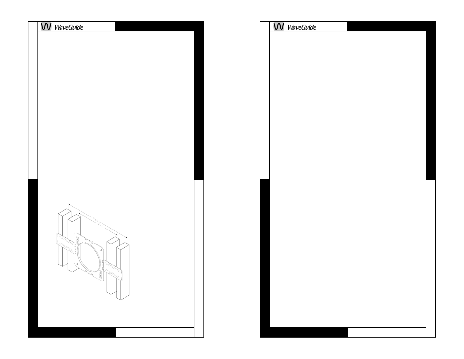
Step 1. Speaker mounting rings are used in the
pre-construction phase of speaker installation
during construction of new homes and additions.
WaveGuide mounting rings are designed to
provide drywall installers the correct cut-out
pattern for the
speakers. The
mounting rings
have “flaps” that
are nailed/
screwed/
stapled onto the
joist. See figure
1. Once the wall
board is
FIGURE 1
When installing the mounting ring, note that there
are holes molded into the mounting ring for
installed, the
opening is cut
out to mount
the speaker.
If you require to disperse the sound in a 360degree pattern you must position the line in the
tweeter in a horizontal position. See figure 5 on
page 10.
The combination of switch settings allow you to
boost and cut bass and treble +/-3dB. Adjust the
speaker level to accommodate for room
acoustics. See figure 6 on page 10.
Step 13. Divide each adhesive bead strip in half.
(Adhesive bead strips are in the clear self-closing
bag). Place strips on the edge of the grille as
shown in figure 7 on page 10. Reinstall the grille
on the speaker.
Step 14. Adhere the WaveGuide logo to the grille
with the pressure sensitive tape.
Repeat steps for the second speaker.
In-wall Speakers
For existing construction, the use of rough-in
rings can not occur. The following steps outline
how to locate a section between two wall studs,
mark the outer boundaries of the hole, drill a
small hole in the center to verify the location and
then cut the main hole.
Step 1. Determine the location of the wall studs
so the speaker can be centered approximately
between them. There are several ways to go
about this:
• Use an electronic stud finder. Many stud
finders can also indicate the location of live
AC wiring.
• Tap on the wall and listen to the resulting
Page 6
Page 19
Page 7
TM
TM
stranded cable so the wires are tight.
Step 10. Follow the instructions included with the
volume control and amplifier.
Step 11. You are now ready to install the
speaker. Remove the paint mask from the baffle.
Be careful not to touch the speaker cones and
tweeter when removing the paint mask in
order to prevent any damage. Attach the
speaker cable to the speaker by pressing down
on the red (+) or black (-) gold-plated push
terminals and inserting the red wire in the red
terminal and the black wire in the black terminal.
See Figure 3 on page 8. Make sure that none of
the strands from the black and red wires are
touching each other. This can create a short
circuit that can damage your electronics. Index
the mounting tabs to make sure that all tabs will
clear the opening. Insert the speaker in the
ceiling and tighten the tabs with the screws on
the front of the grille. DO NOT OVERTIGHTEN
THE SCREWS, the screws should only be tight
enough to secure the speaker.
Step 12. After the speaker is mounted,
adjustments to the swivel tweeter (small speaker)
can be made by either directing the sound
visually or by using a musical source to
determine the best sound coverage for the
listening area. To position the tweeter, press at
the outside edge of the tweeter housing (DO
NOT PRESS ON THE TWEETER CONE
DIRECTLY).
Note the crease in the asymmetrical tweeter
provides the highest directional response in this
direction. See figure 4 on page 9.
speaker wire tie-off.
TIPS FOR NEW CONSTRUCTION
• If possible, run speaker wires after AC
wiring is in place to avoid additional noise
caused by close proximity of wiring.
• Secure the speaker wires against a joist with
insulated staples, being careful not to pierce
the wire insulation. Allow slack for building
material expansion.
• Horizontal wire runs should be routed through
holes drilled at equal heights in the joist.
• Do not install the actual speaker until the wall
board is in place. Until then leave several feet
of wire secured to the back of the mounting
ring. The excess wire can be removed during
final installation.
• During the drywall installation, make sure the
speaker cut-out hole does not extend farther
than 1/4 inch from the inside of the mounting
ring. The flat rough-in rings and flaps are thin
enough that they won’t interfere with wall
board installation.
FIGURE 2
Step 2. After
you have
determined
the speaker
locations
using the
guidelines
above, secure a 16
gauge 2conductor
cable to the
mounting ring
Page 18
Page 7
Page 8
TM
TM
tabs (see figure 2), such as the M&S Systems
MS16X, for attachment to the speakers after the
dry wall has been installed. Leave at least 18
inches additional cable for the connection during
final speaker installation. Run the other end of
the speaker cable to the audio source.
NOTE: Make a drawing of each speaker location.
This will assist you in locating the wires if they
have been covered after the wall board has been
installed.
Step 3. This is the finish-out stage. Prepare the
speaker wiring by stripping off approximately 3
inches of the outer jacket (care should be taken
so the insulation on the wires inside the jacket
are not damaged) also strip approximately 3/8
inch off the ends of the two inside conductors.
Twist the ends of the stranded cable so the wires
are tight.
Step 4. Follow the instructions included with the
volume control and amplifier.
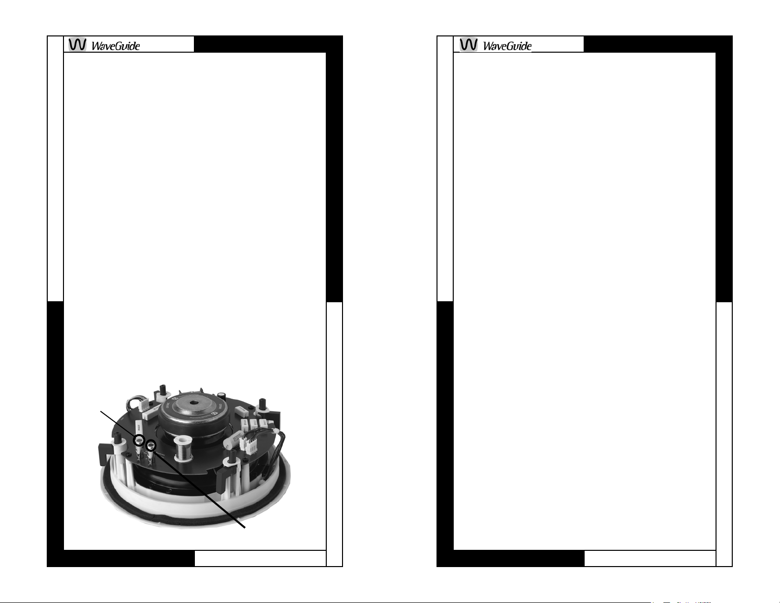
Step 5. You are now ready to install the speaker.
FIGURE 3
Positive
(red)
Negative (black)
pencil outline which you have just drawn, just
deep enough to fully penetrate the drywall.
Step 4. Obtain a length of stiff wire such as a
straightened wire cost hanger. Bend it so that the
last 6 or 8 inches is at a right angle to the rest.
Step 5. Insert the bent part into the 1-inch hole
you just drilled and probe to the left and the right
to confirm that a joist is not too close on either
side. Move the wire around in a circular motion to
check clearances above and below the hole as
well.
Step 6. If there are no obstructions, carefully
score the penciled outline of the template with a
sharp utility knife to avoid chipping paint or
tearing wallpaper. Then use a drywall or keyhole
saw to cut along the scored line. Make sure that
you do not cut the hole larger than the outline.
Step 7. Be sure to clear any insulation material
from the speaker back.
Step 8. After you have determined the speaker
locations secure a 16 gauge 2 conductor cable to
the joist using an insulated staple. Leave at least
18 inches of additional cable for connection during final speaker installation. Run the other end of
the speaker cable to the audio source.
Step 9. Prepare the speaker wiring by stripping
off approximately 3 inches of the outer jacket
(care should be taken so the insulation on the
wires inside the jacket are not damaged) also
strip approximately 3/8 inch off the ends of the
two inside conductors. Twist the ends of the
Page 8
Page 17
Page 9

TM
TM
Speaker Installation
for Existing Construction
Ceiling Speakers
For existing construction, the use of mounting
rings can not occur. The following steps outline
how to locate a section between two joists, mark
the outer boundaries of the hole, drill a small hole
in the center to verify the location and then cut
the main hole.
Step 1. Determine the location of the joists so the
speaker can be centered approximately between
them. There are several ways to go about this:
• Use an electronic stud finder. Many finders
can also indicate the location of live AC
wiring.
• Tap on the wall and listen to the resulting
sound. When the sound is deeper and more
hollow sounding, you are between joists.
When the sound is sharper and more flat
sounding, you are close or over a stud.
• Identify joists by the position of electrical
light fixtures. There may be a joist directly to
the left or right of these electrical fixture. This
gives you a point of measurement since joists
are either 24 or 16 inches on center in newer
houses, 12 inches in older homes.
Step 2. When you are sure of where the ceiling’s
joists are (and are completely sure there isn’t an
electrical cable, water pipe or heating duct in that
vicinity of the wall), position the cardboard
mounting template, and draw around the outer
perimeter with a pencil.
Step 3. Drill a 1-inch hole in the center of the
Remove the paint mask from the baffle. Be
careful not to touch the speaker cones and
tweeter when removing the paint mask in
order to prevent any damage. Attach the
speaker cable to the speaker by pressing down
on the red (+) or black (-) gold-plated push
terminals and inserting the red wire in the red
terminal and the black wire in the black terminal.
See Figure 3. Make sure that none of the strands
from the black and red wires are touching each
other. This can create a short circuit that can
damage your electronics. Index the mounting
tabs to make sure that all tabs will clear the
opening. Insert the speaker in the ceiling and
tighten the tabs with the screws on the front of
the grille. DO NOT OVERTIGHTEN THE
SCREWS, the screws should only be tight
enough to secure the speaker.
Step 6. After the speaker is mounted,
adjustments to the swivel tweeter (small speaker)
can be made by either directing the sound
visually or by using a musical source to
determine the best sound coverage for the
listening area. To position the tweeter, press at
FIGURE 4
the outside
edge of the
tweeter housing
(DO NOT
PRESS ON THE
TWEETER
CONE
DIRECTLY).
Note (see
figure 4) the
tweeter
horn
Crease position
crease in the
asymmetrical
Page 16
Page 9
Page 10

TM
TM
tweeter
horn
FIGURE 5
tweeter provides
the highest
directional
response in this
direction.
See figure 5. If
you require to
disperse the
sound in a 360degree pattern
you must
position the line
crease position
in the tweeter in
a horizontal
position.
See figure 6. The
combination of switch
settings allow you to
boost and cut bass
and treble +/-3dB.
Adjust the speaker
level to accommodate
FIGURE 6
for room acoustics.
Step 7. Divide each
adhesive bead strip
in half. (Adhesive
bead strips are in the
clear self-closing
bag). Place strips on
the edge of the grille
FIGURE 7
as shown in figure 7.
Reinstall the grille on
the speaker.
Step 8. Adhere the WaveGuide logo to the grille
with the pressure sensitive tape.
Repeat the steps for the second speaker.
Tweeter horn
Crease position
FIGURE 12
FIGURE 13
Step 7. Divide each
adhesive bead strip
in half. (Adhesive
bead strips are in the
clear self-closing
bag). Place strips on
the edge of the grille
as shown in figure
14. Reinstall the grill
on the speaker.
Step 8. Adhere the
WaveGuide logo to
the grille with the
pressure sensitive
tape.
Repeat the steps for
the second speaker.
FIGURE 14
Page 10
Page 15
Page 11
TM
TM
touching each other. This can create a short
circuit that can damage your electronics. Mount
the baffle using the 6 screws provided. DO NOT
OVERTIGHTEN THE SCREWS, the screws
should on only be tight enough to secure the
speaker.
Step 6. After the speaker is mounted,
adjustments to the swivel tweeter (small speaker)
can be made by either directing the sound
visually or by using a musical source to
determine the best sound coverage for the
listening area. To position the tweeter, press at
the outside edge of the tweeter housing (DO
NOT PRESS ON THE CONE DIRECTLY).
Note the crease in the asymmetrical tweeter
provides the highest directional response in this
Tweeter horn
direction. See figure
11.
If you require to
disperse the sound
in a 360-degree
pattern you must
position the line in
the tweeter in a
horizontal position.
See figure 12.
The combination of
switch settings allow
you to boost and cut
bass and treble +/3dB. Adjust the
Crease position
FIGURE 11
speaker level to
accommodate for
room acoustics. See
figure 13.
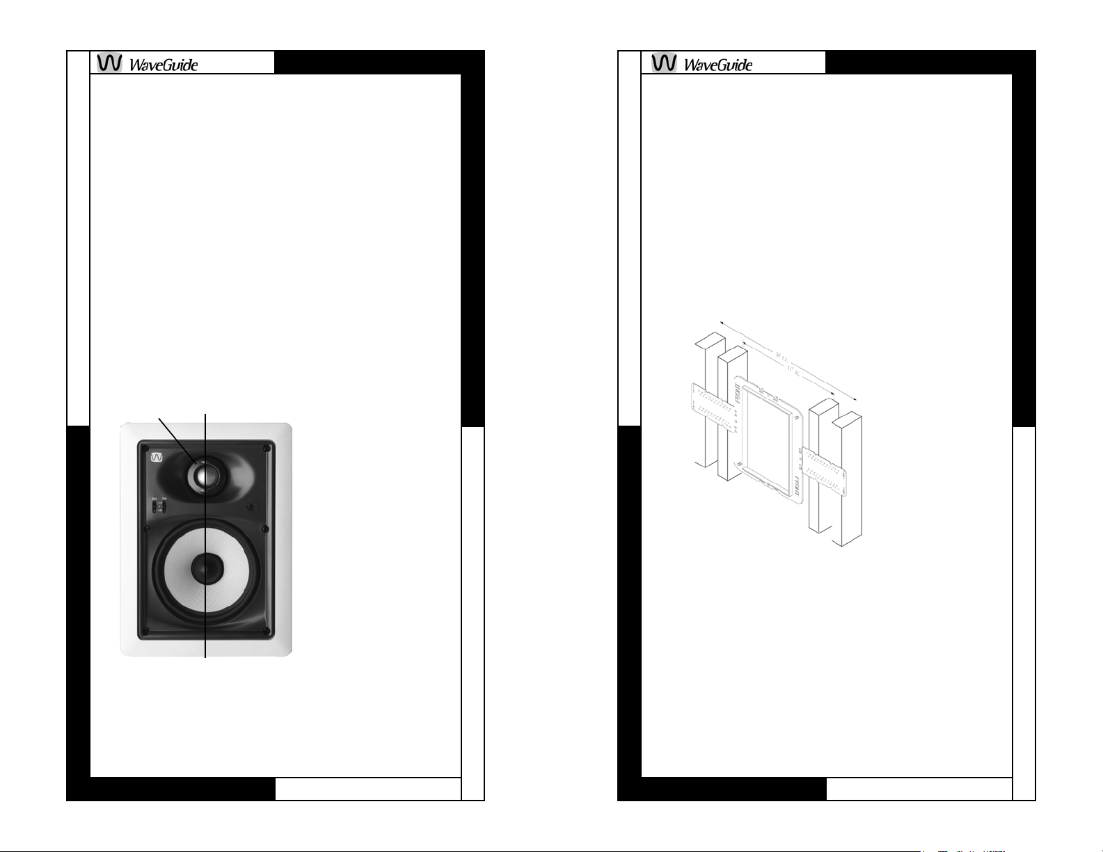
In-wall Speakers
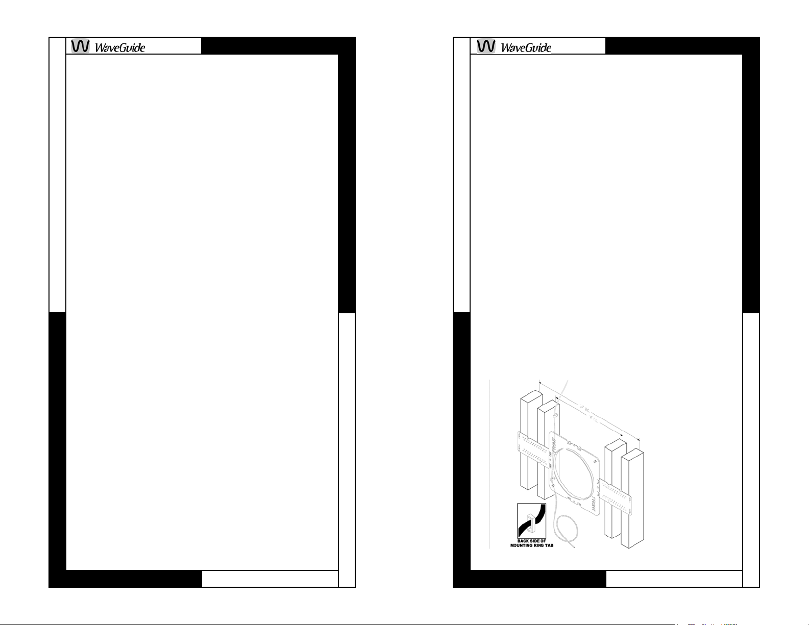
Step 1. Speaker mounting rings are used in the
pre-construction phase of speaker installation
during construction of new homes and additions.
WaveGuide mounting rings are designed to
provide drywall installers the correct cut-out
pattern for the speakers. The rings have “flaps”
that are nailed/screwed/stapled onto the studs.
See figure 8.
Once the wall board is installed, the opening is
cut out and the speaker frame is inserted into the
mounting ring.
When installing
the mounting
ring, note that
there are holes
molded into the
mounting ring
for speaker
wire tie-off.
FIGURE 8
TIPS FOR NEW CONSTRUCTION
• Use a small level to verify that the mounting
ring is straight.
• If possible, run speaker wires after AC
wiring is in place to avoid additional noise
caused by close proximity of wiring.
• Secure the speaker wires against a stud with
insulated staples, being careful not to pierce
the wire insulation. Allow slack for building
material expansion.
Page 14
Page 11
Page 12

TM
TM
• Horizontal wire runs should be routed through
holes drilled at equal heights in the studs.
• Do not install the actual speaker until the wall
board is in place. Until then leave several feet
of wire secured to the back of the mounting
ring. The excess wire can be removed during
final installation.
During the drywall installation, make sure the
speaker cut-out hole does not extend farther than
1/4 inch from the inside of the mounting ring. The
flat rough-in rings and flaps are thin enough that
they won’t interfere with installation.
Step 2. After you have determined the speaker
locations using the guidelines above, secure a 16
gauge 2 conductor cable to the mounting ring
tabs (see figure
9), such as the
M&S Systems
MS16X, for attachment to the
speakers after
the dry wall has
been installed.
Leave at least
18 inches
additional cable
for the
connection
during final
FIGURE 9
speaker
installation.
Run the other end of the speaker cable to the
audio source.
NOTE: Make a drawing of each speaker location.
This will assist you in locating the wires that have
been covered after the sheet rock has been
installed.
Step 3. This is the finish-out stage. Prepare the
speaker wiring by stripping off approximately 3
inches of the outer jacket (care should be taken
so the insulation on the wires inside the jacket
are not damaged) also strip approximately 3/8
inch off the ends of the two inside conductors.
Twist the ends of the stranded cable so the wires
are tight.
Step 4. Follow the instructions included with the
volume control and amplifier.
Step 5. You are now ready to install the frame.
Remove the paint mask. Be careful not to touch
the speaker cones and tweeters when
removing the paint mask in order to prevent
any damage. Remove the baffle from the frame
and fasten the frame to the pre-construction
bracket. Attach the speaker cable to the speaker
by pressing down on the red (+) or black (-) goldplated push terminals and inserting the red wire
in the red terminal and the black wire in the black
terminal. See figure 10. Make sure that none of
the strands from the black and red wires are
Negative
(black)
Positive
(red)
FIGURE 10
Page 12
Page 13
 Loading...