

Page 1

TABLE OF CONTENTS
SECTION DESCRIPTION
PAGE
1 .............................Theory of Operation.................................................................................2
2 .............................Glossary................................................................................................ 2-5
3 .............................General Description.................................................................................6
4 .............................Installation .......................................................................................... 7-17
5 .............................Adjustments ..................................................................................... 18-22
6 .............................Changing the INTERSECTOR IP Address...................................... 23-31
7 .............................Maintenance ..................................................................................... 32-33
8 .............................Parts List.................................................................................................34
9 .............................Electrical Interconnection Details & Drawings ...................................34
10 ...........................Schematics .............................................................................................34
11............................Assembly Drawings...............................................................................34
Appendix A............ Simulation Mode .......................................................................... A-1, A-2
Appendix B............TCIB Connections................................................................................... B
Appendix C............Windows 7 Set-Up...................................................................................C
Addendum.............Changes in 1.9U Software...................................................Addendum-1
MS Sedco INTERSECTOR Installation Instructions Page 1 INTERSECTOR-1.9Uv092717
Page 2

INTERSECTOR
Microwave Motion and
Presence Sensor Installation Instructions
NOTE: For information concerning changes made to INTERSECTOR software
revision 1.9U, please see the Addendum at the end of this manual.
THEORY OF OPERATION
The INTERSECTOR sensor uses FSK microwave radar to identify, classify, and track
vehicles by position and speed. This information is overlaid in an X-Y coordinate
system, allowing users to set up detection zones. Presence of a vehicle in a
user-defined zone will produce an output to the control output. Users are able to set a
maximum presence time, and associate unique outputs, time delays, or output delays
with individual zones.
The interface board monitors whether the sensor is functioning, and provides a means
for end users to set up zones via a connection to a laptop computer. It also provides the
outputs to the control panel, and includes LEDs which allow end users to verify
operation without having to connect to the laptop.
GLOSSARY
MAIN SCREEN: The main screen is the first screen that will be displayed when the
INTERSECTOR is connected to the Setup Port of the Interface board and a laptop is also
connected to the Laptop Ethernet Port. From the Main Screen you will have two
options: 1. SETUP
2. ZONE SETTING
SETUP: This page will give the installer five options:
1. SIMULATION MODE ON: This turns on SIMULATION MODE and will allow the
installer to set the number of vehicles that will be displayed in SIMULATION
MODE.
2. SIMULATION MODE OFF: Turns off SIMULATION MODE so you can monitor live
traffic again.
3. SET DEFAULT VALUES: This will allow the installer to reset the sensor to factory
settings.
4. DELAY BEFORE MAX: Controls how long the target vehicle will be detected
before the target will be changed to OZP/MAX presence timer.
5. OZP/MAX TIME: Occlusion Zone Protection (OZP) is a timer that will count
down the value set in the OZP/MAX TIME field. This timer will begin when the
Delay Before Max timer has expired, or if occlusion occurs, and a vehicle
disappears from the zone. When the OZP/MAX TIME reaches 0, the vehicle will be
dropped from the zone. It is recommended that the value for the OZP/MAX TIME is
set relatively short (20 seconds), to avoid vehicles being held for long periods.
The vehicle ID will be highlighted in a yellow box while the OZP timer is active.
6. SET RF CHANNEL: Assigning a value of 1-7 in this field will select the RF channel
that the INTERSECTOR sensor will use for operation. For best results, use a
different channel for each sensor used at an intersection.
MS Sedco INTERSECTOR Installation Instructions Page 2 INTERSECTOR-1.9Uv092717
Page 3
INTERSECTOR
Microwave Motion and
Presence Sensor Installation Instructions
GLOSSARY (continued)
ZONE SETTING: This is the main entry to the PROGRAMMING SCREEN for the
INTERSECTOR.
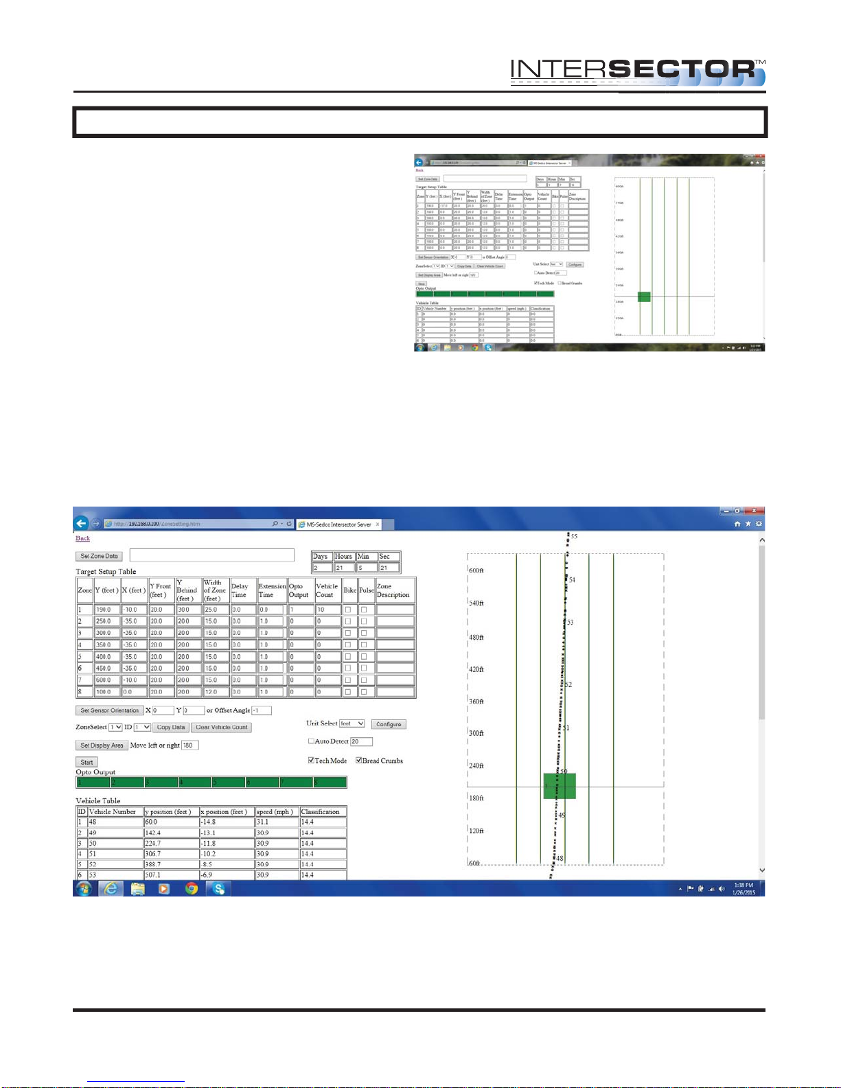
PROGRAMMING SCREEN: This is the area where the installer can setup detection zones,
Offset Angle, and track vehicle progress. This screen consists of three main parts: The
TARGET SETUP TABLE, VEHICLE TABLE, and DATA DISPLAY.
SET ZONE DATA: This function stores zone data to hard memory. When any data is
changed on the PROGRAMMING SCREEN, it will only be stored when this is selected.
TARGET SETUP TABLE: This section of the PROGRAMMING SCREEN is where all setup
data will be entered to be installed to the INTERSECTOR. The Table consists of several
data values:
• ZONE: Zone is the term used to describe the area where the vehicle will be
detected. In some cases this is known as the “loop”. Up to 8 separate zones
can be created.
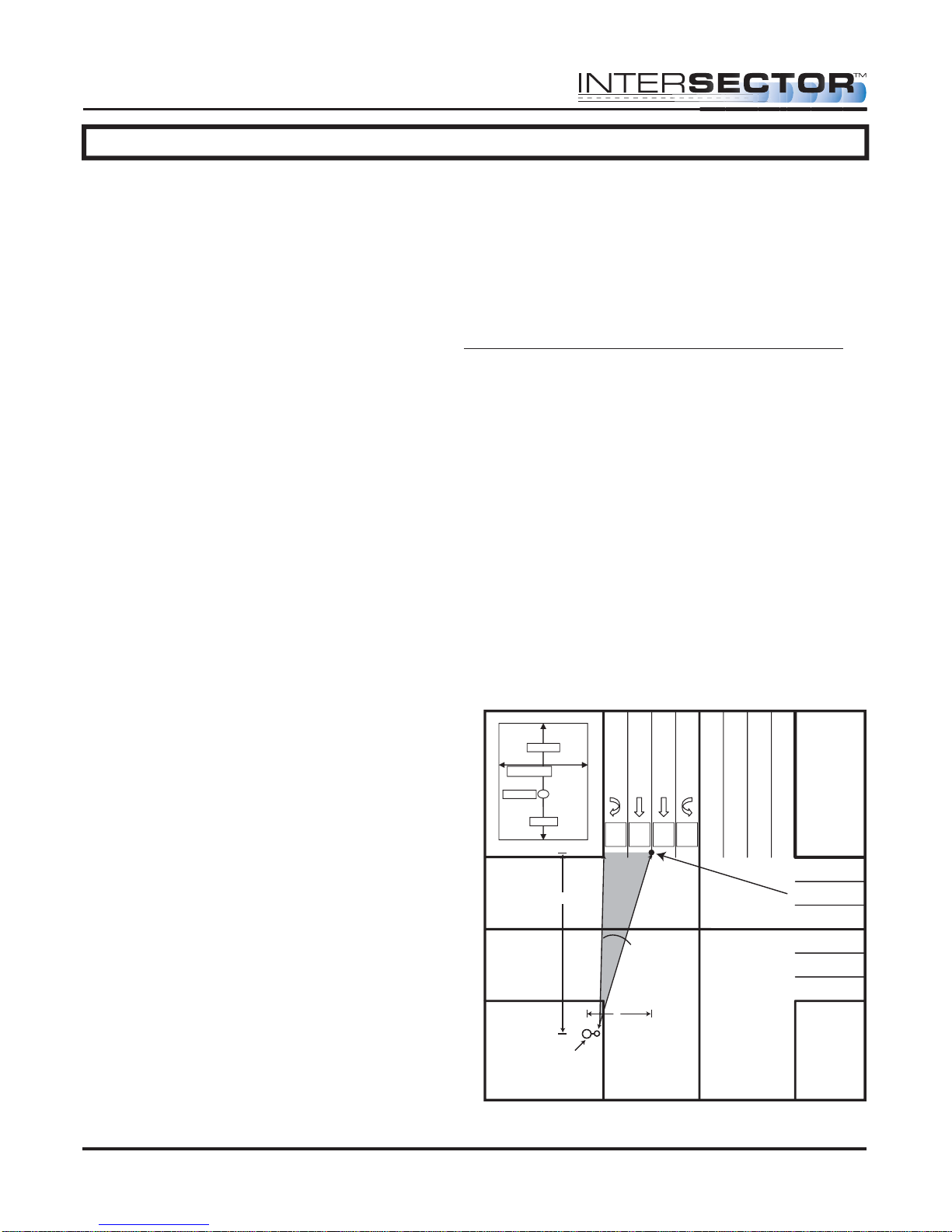
• X: X is the first coordinate used to determine the location of a zone. The
X coordinate is the horizontal dimension and represents the distance from the
sensor to the center of the zone in the X axis (Diagram 1).
• Y: Y is the second coordinate used to determine the location of a zone. The
Y coordinate is the vertical dimension and represents the distance from the
sensor to the center of the stop bar zone (Diagram 1).
• Y Front: This value extends the zone in front of the original point (closer to
the intersection).
• Y Behind: This value is the depth of the zone behind the original point
(farther from the intersection).
• Width of Zone: This is the width of
the zone in relation to its center.
• DELAY TIME: Time that the detector
will wait before allowing the output
to be recognized.
• EXTENSION TIME: Time that the
output will extend after a vehicle
leaves the zone.
• OPTO OUTPUT: This value indicates
the output for the controller input
(rack). A setting of 0 indicates the
output for this zone is currently
disabled.
Zone 1
Width of lane
X and Y
Y behind
Y front
Zone 1
Opto 2
Opto 1
Y
Offset Angle
X
Opto 3
Opto 4
Center of
Stop Bar Zone
Zone 4
Zone 3
Zone 2
MS Sedco INTERSECTOR Installation Instructions Page 3 INTERSECTOR-1.9Uv092717
Corner Pole /
Sensor Location
NOTE: Unit mounts on
side of pole.
Page 4

INTERSECTOR
Microwave Motion and
Presence Sensor Installation Instructions
GLOSSARY (continued)
• VEHICLE COUNT: This is the total count of all vehicles that have entered this
zone.
• BIKE: Selecting “Bike” will ignore larger vehicles and send a signal if
a bike is present in the zone and moving at a speed of 18 mph (29 kph) or slower
for those who want to provide additional time when bicycles are present.
• PULSE: This setting is used as a vehicle counter, typically in the advanced
detection zone. When in PULSE MODE, a 0.125 second pulse for every vehicle
that enters the zone will be displayed. The zone will not be held, and will display
only one pulse per car. A zone in PULSE MODE will be highlighted in blue while a
vehicle is present.
• ZONE DESCRIPTION: User defined description of the zone that has been set up.
• BREAD CRUMBS: This feature simplifies zone alignment by displaying the path
that each detected vehicle has traveled, illustrating lanes of traffic flow.
• TECH MODE: Technician Mode - this display control allows the service
technician to observe the operation as vehicles pass through the zone. Normally
indication would specify merely detection or non-detection (On or Off).
Technician Mode will also allow the technician to observe if the vehicle has
stopped in DELAY BEFORE MAX or if it is in OZP.
• DAYS, HOURS, MINUTES, AND SECONDS: This indicates the service time of the
sensor.
• SET SENSOR ORIENTATION: This is the section where the X and Y coordinates
are entered to calculate the Offset Angle that will allow electronic alignment of the
sensor to the center of the desired detection area. Installers may enter the X and
Y coordinates, or the Offset Angle. If the X and Y coordinates are entered, the
Offset Angle will be automatically calculated. The Offset Angle can then be
modified if necessary.
1. X is the distance left or right of the sensor to the center of the desired
detection area (left will be a negative number, right will be positive).
2. Y is the distance from the sensor to the center of the stop bar zone.
3. Offset Angle is typically between -12° to +12°.
TABLE SETUP SECTION: This section consists of features useful in setting up the
TARGET SETUP TABLE.
ZONE SELECT: This value selects the zone to be programmed.
ID: This value selects the identification of a vehicle in the VEHICLE TABLE which can
be found directly below this setting. This value is used to copy the data of the
selected vehicle.
COPY DATA: Selecting this feature will enter the information for the selected ID to
the corresponding zone selected in Zone Select, in the TARGET SETUP TABLE.
MS Sedco INTERSECTOR Installation Instructions Page 4 INTERSECTOR-1.9Uv092717
Page 5

INTERSECTOR Microwave Motion and
Presence Sensor Installation Instructions
GLOSSARY (continued)
CLEAR VEHICLE COUNT: Resets the VEHICLE COUNT for all zones.
• UNIT SELECT: This feature will allow information to be entered in either feet
or meters. Changing from one unit to the other will automatically convert
numerical data in the table.
• CONFIGURE: Selecting the configure button will open a drop down menu that
will allow outputs to be assigned certain features, such as Tail Extensions,
Wrong Way detection, or speed ranges. For more information on Configure
options, please see page 18 in the Adjustments section.
SET DISPLAY AREA: Repositions the DATA DISPLAY area based on the following
settings:
• MOVE LEFT OR RIGHT: Moves the DATA DISPLAY area left or right based on
the value entered. A negative value moves left, a positive value moves right.
STOP/START: This feature is used to Stop or Start the display of live data. The main
use is to stop the display of data when a vehicle is present at a desired location. The
data for this vehicle can then be copied into the TARGET SETUP TABLE using Copy
Data, to establish a zone.
OPTO OUTPUT: This is a visual indication of the sensor outputs that correspond to
the interface board LEDs.
VEHICLE TABLE: This is a real time data table for the vehicle activity shown on the
DATA DISPLAY. This information can be used for setting up zones or tracking
intersection activity. When the Stop button is selected, the data displayed will pause,
and can be copied to the TARGET SETUP TABLE. The actual data will continue to be
gathered, even when the displayed data is paused. When the live display is restarted,
the data will update to show the current values.
ID: The ID number is assigned to a vehicle (Vehicle Number) to aid in copying the
data to the TARGET SETUP TABLE.
VEHICLE NUMBER: This is the vehicle number that appears in the DATA DISPLAY
area of the screen.
X POSITION: This is the X position of the corresponding vehicle as it relates to the
sensor.
Y POSITION: This is the Y position of the corresponding vehicle as it relates to the
sensor.
SPEED: This is the speed for the corresponding vehicle.
DATA DISPLAY: This is the area that graphically displays the vehicle activity detected by
the sensor.
MS Sedco INTERSECTOR Installation Instructions Page 5 INTERSECTOR-1.9Uv092717
Page 6
INTERSECTOR
Microwave Motion and
Presence Sensor Installation Instructions
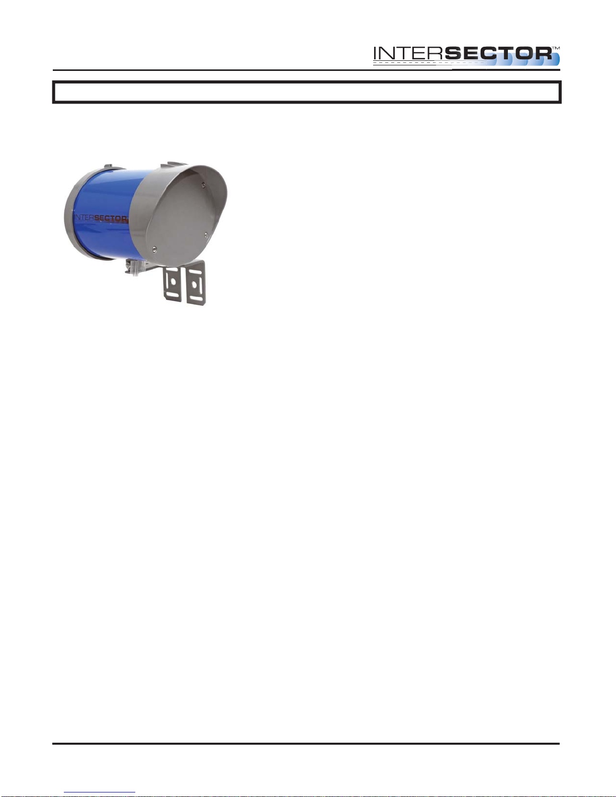
GENERAL DESCRIPTION
The INTERSECTOR is a microwave vehicle motion and presence tracking sensor
designed for intersection control. The INTERSECTOR offers several advantages when
compared to cameras or loop detectors:
• Detection is not affected by weather
• Immune to sunrise/sunset or post-rain glare
• Not susceptible to in-road breakage
• Multiple lanes can be covered by a single unit
• Easily installs overhead to corner signal poles
(Traffic lane closure may not be required)
• No privacy concerns
• Reduces construction costs
(no special poles/bucket trucks required)
Through its user interface, the INTERSECTOR allows users to visually track vehicles as
they approach the intersection and allows easy setup of detection zones to provide
programmable inputs to a traffic control cabinet. The interface also provides the ability
to verify that the system is functioning properly, or to troubleshoot the system, using a
SIMULATION MODE.
MS Sedco INTERSECTOR Installation Instructions Page 6 INTERSECTOR-1.9Uv092717
Page 7

INTERSECTOR
Microwave Motion and
Presence Sensor Installation Instructions
INSTALLATION
INSTALLATION PREPARATION
NOTE: Remember to read all installation instructions carefully prior to
!
installation of the unit. For a quicker installation, carefully pre-screen installation
location. Prior to installation of the INTERSECTOR, please complete the
INTERSECTOR worksheet. The worksheet is included with this manual.
Please inspect mounting location to ensure the following criteria are met:
• Mounting height should be between 14 feet and 20 feet.
• Distance from the sensor to the stop bar should not exceed 140 feet.
• Distance from the sensor to the closest detection zone should be at least 50 feet.
• Typical range of the TC-CK1-SBE is 600 feet.
• The TC-CK1-SBE has a detection width of 30 degrees. For best results the sensor
should be mounted at a tilt angle between horizontal to 3 degrees downward plus or
minus the road slope.
• Installation requires a laptop with Internet Explorer version 6.0 or greater, at least
2 GB RAM available, safe cable & Ethernet cable.
TOOL REQUIREMENTS:
To properly install the INTERSECTOR, it is necessary to have the following tools on
hand:
• Angle Meter • Ethernet Cable Tester
• 7/16” Box Wrench or Socket • Modular Plug Termination Tool
(Crimp Tool)
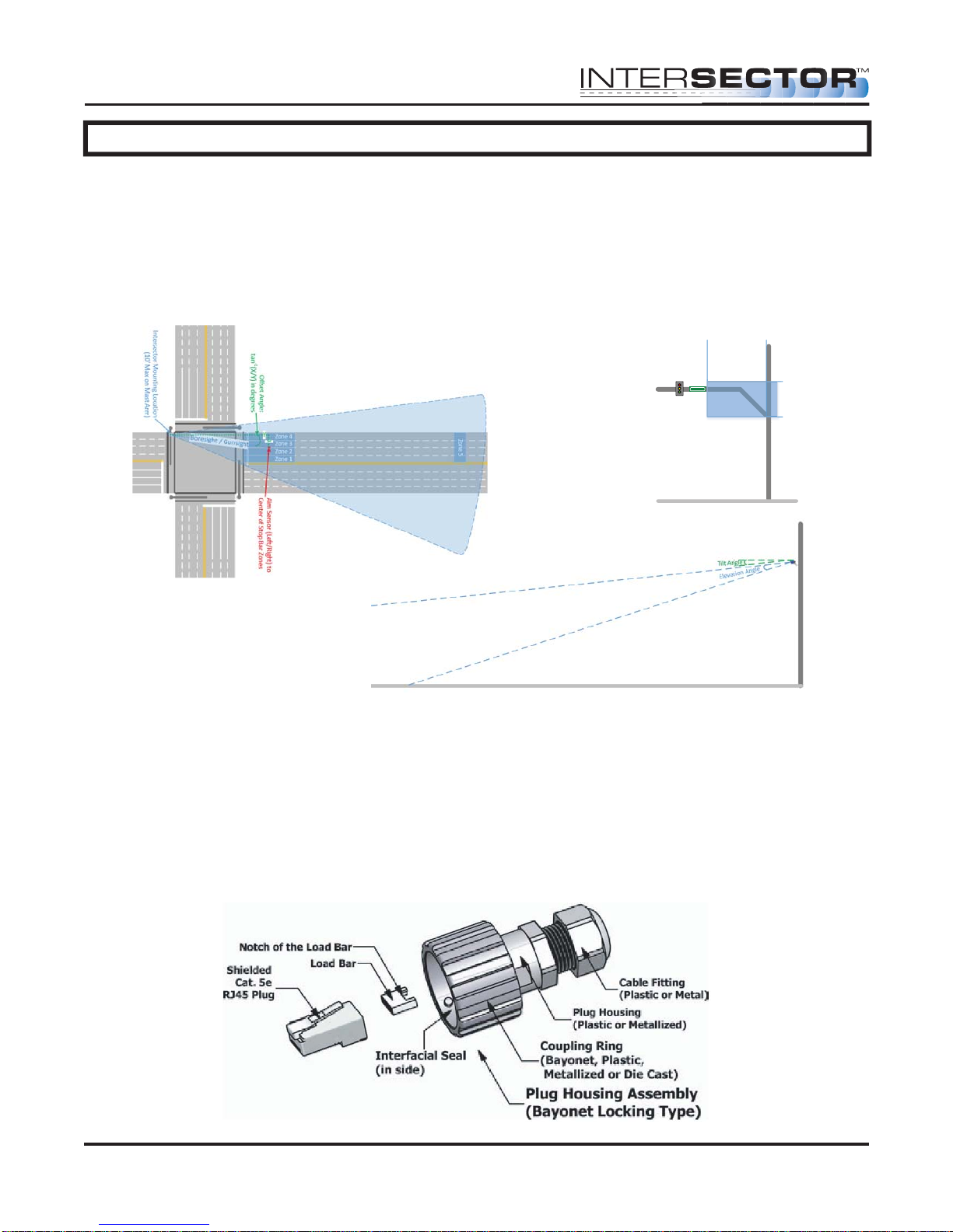
The INTERSECTOR is designed to be mounted at a height of 14 to 20 feet on a corner
signal pole or on a mast arm no further than 10 feet from the signal pole. Maximum
offset angle from traffic direction should be ±15 degrees. Mounting outside this range
may reduce performance. Mount the sensor to the pole using stainless steel banding or
bolts (not included). Make sure the sensor is mounted level.
INTERSECTOR ANGLE SETTINGS:
There are two angle settings for the INTERSECTOR; side to side (azimuth) and up and
down (elevation). The azimuth setting is accomplished visually using the gun sight at
the top of the unit. Aim the gun sight across the center of the stop bar region. Check to
ensure that cars should be tracked approximately 30 feet past the stop bar for a left turn
lane. To set the elevation, use the angle meter which is included in the INTERSECTOR
installation kit. The Installation Table Recommended Settings below provides initial
settings for installation, based on the distance to the stop bar. These settings may need
additional adjustment depending on factors such as the slope of the road. Rotating the
unit downward will decrease total range, but will ensure detection closer to the unit.
MS Sedco INTERSECTOR Installation Instructions Page 7 INTERSECTOR-1.9Uv092717
Page 8
INTERSECTOR
14'
20'
0'
10'
Intersector
Mounng Area
Microwave Motion and
Presence Sensor Installation Instructions
INSTALLATION (continued)
Distance ............Max # ................Angle Mounting........................ Height
to Stop Bar Lanes (˚) (ft.)
60-80 feet .................... 2 ...............................-6 degrees .....................................16 feet
80-100 feet .................. 3 ...............................-6 degrees .....................................17 feet
100-120 feet ................ 4 ...............................-4 degrees .....................................18 feet
120-160 feet ................ 4 ...............................-2 degrees .....................................19 feet
FIGURE 1: INTERSECTOR™ Installation Example
FIGURE 2: Recommended INTERSECTOR™
Mounting Location Depiction
FIGURE 3: INTERSECTOR™ Tilt and
Elevation Angle
Connection of the sensor to the traffic cabinet is accomplished using an Ethernet cable.
The cable is routed through a quick connect assembly that is then connected to the
sensor. The other end of the cable is routed to the traffic cabinet and plugs into the
interface board. The next section will detail the preparation and installation of the
sensor Ethernet cable.
QUICK CONNECT ASSEMBLY INSTRUCTIONS:
The quick connect consists of a shielded Cat. 5e RJ45 Plug, a load bar, and a Plug
Housing Assembly.
MS Sedco INTERSECTOR Installation Instructions Page 8 INTERSECTOR-1.9Uv092717
Page 9

INTERSECTOR Microwave Motion and
Presence Sensor Installation Instructions
INSTALLATION (continued)
It is necessary to prepare the cable and insert it through the housing prior to attaching
the load bar and Ethernet connector (RJ45 plug).
NOTE: Cat.5e direct burial shielded cable is recommended to keep
!
Electromagnetic Interference, or (EMI), from effecting the ability of the cable to
transmit data. EMI can pass through the cable, corrupting your data and shutting
down communication. The Shielding in the wire helps to prevent this energy from
getting through and causing adverse effects to the TC-CK1-SBE communication
data.
CABLE PREPARATION: Using an 8 conductor, 24 AWG per conductor solid or stranded
cable, the cable jacket should be stripped as shown in Figure 1 and then inserted
through the cable fitting and the plug housing assembly.
Strip 25mm length approx.
Conductor
Jacket
Figure 1
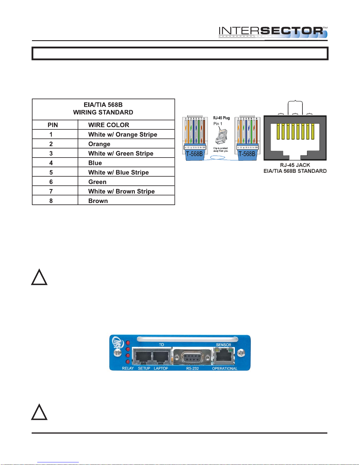
Conductors should be untwisted and aligned side by side for a T568B connector. Refer
to Figure 2 to determine the proper alignment of the cable conductors.
Figure 2
Figure 3
The conductor wire ends should be trimmed as shown in Figure 3. Untwist as little of
the cable as possible. Be careful not to remove the insulation of individual conductors!
MS Sedco INTERSECTOR Installation Instructions Page 9 INTERSECTOR-1.9Uv092717
Page 10
INTERSECTOR Microwave Motion and
Presence Sensor Installation Instructions
INSTALLATION (continued)
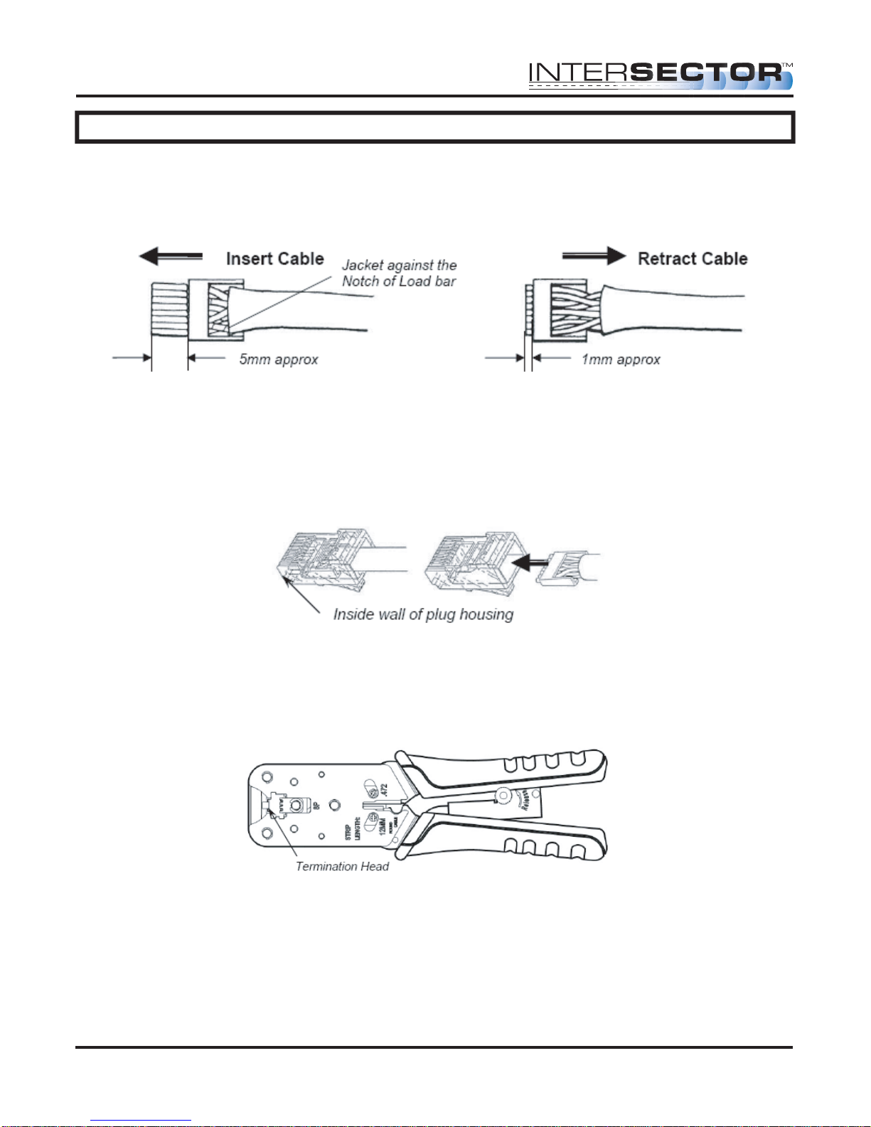
After inserting the wires into the appropriate positions of the load bar, slide the cable to
a point where the cable jacket hits the notch of the load bar. Trim the remaining wire
ends to approximately 5mm length as shown in Figure 4. Retract the cable, leaving
approximately 1mm of wire tips as shown in Figure 5.
Figure 4 Figure 5
Insert the wired load bar into the RJ45 plug all the way until the wire tips are sealed
against the inside wall of the plug housing (Figure 6).
IMPORTANT – No wires should be exposed when the plug is fully in place.
Figure 6
Terminate the cable and the RJ45 plug with a modular plug termination tool similar to
the one shown in Figure 7.
Figure 7
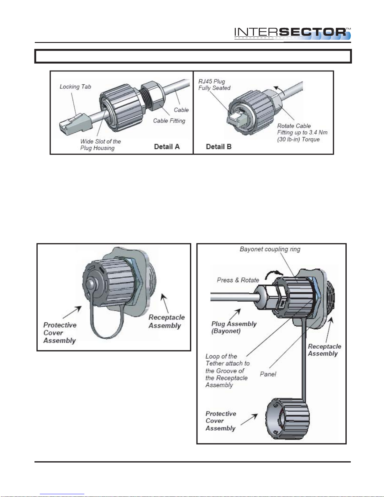
Depress the locking tab of the RJ45 plug and align it with the wide slot of the plug
housing shown in Figure 8 Detail A. Gently pull the cable until the plug is fully seated.
Hold the plug in position and rotate cable fitting until tightened to a torque of 3.4 Nm (30
lb-in) as shown in Figure 8 Detail B.
MS Sedco INTERSECTOR Installation Instructions Page 10 INTERSECTOR-1.9Uv092717
Page 11
INTERSECTOR Microwave Motion and
Presence Sensor Installation Instructions
INSTALLATION (continued)
Figure 8
Once the quick connector assembly is completed attach the cable to the sensor.
Remove the protective cover from the sensor receptacle assembly (Figure 9) by gently
rotating the cover counter clockwise. Gently insert the assembled plug (Bayonet) into
the jack adaptor of the RJ45 receptacle, align the 3 keys of the bayonet coupling ring
with the 3 channels of the receptacle, and rotate the bayonet coupling ring until the 3
keys “click” into the bayonet channels (Figure 10).
Figure 9
MS Sedco INTERSECTOR Installation Instructions Page 11 INTERSECTOR-1.9Uv092717
Figure 10
Page 12
INTERSECTOR
Microwave Motion and
Presence Sensor Installation Instructions
INSTALLATION (continued)
INTERFACE CARD INSTALLATION:
Route the other end of the Ethernet cable to your cabinet. Connect the Ethernet
connector to the end of the cable. Configure the Ethernet connector (RJ45 plug) for a
“Straight thru” connection.
Figure 12
Green
Pair 3
Brown
Pair 4
Blue
Pair 1
Orange
Pair 2
Figure 11
NOTE: Your colors may be different than what is shown.
After completing the Ethernet cable, plug the interface card into your traffic cabinet.
• If using the 4 output interface card, ensure that it is plugged into the even slot.
• If using the 2 output interface card, it can be plugged into any slot.
Either card uses 12-24 Volts supplied by the rack in the cabinet.
CAUTION: Power supply must be capable of supplying 1 amp of current to each
!
TCIB card.
Once the interface card is properly installed, plug the Ethernet cable from the sensor
into the setup port of the card. Initially the LEDS will light and stay on when the Ethernet
cable is plugged into the setup port. This is normal and indicates that the unit has not
been completely setup. Once a valid connection is established the LED will light only
when the zone is activated by vehicle detection. The sensor is now ready to program.
SOFTWARE SETUP:
Programming of the INTERSECTOR is performed by connecting the sensor to a
computer. Connect a Laptop/PC to the Laptop Ethernet port.
WARNING: The INTERSECTOR can only be programmed if the Ethernet cable is
!
plugged into the setup port on the interface card. Please ensure proper
connection before proceeding further.
MS Sedco INTERSECTOR Installation Instructions Page 12 INTERSECTOR-1.9Uv092717
Page 13
INTERSECTOR
Microwave Motion and
Presence Sensor Installation Instructions
INSTALLATION (continued)
When the sensor is connected to the setup port, it will receive power from the interface
card.
Set your computer for a Dedicated IP Address:
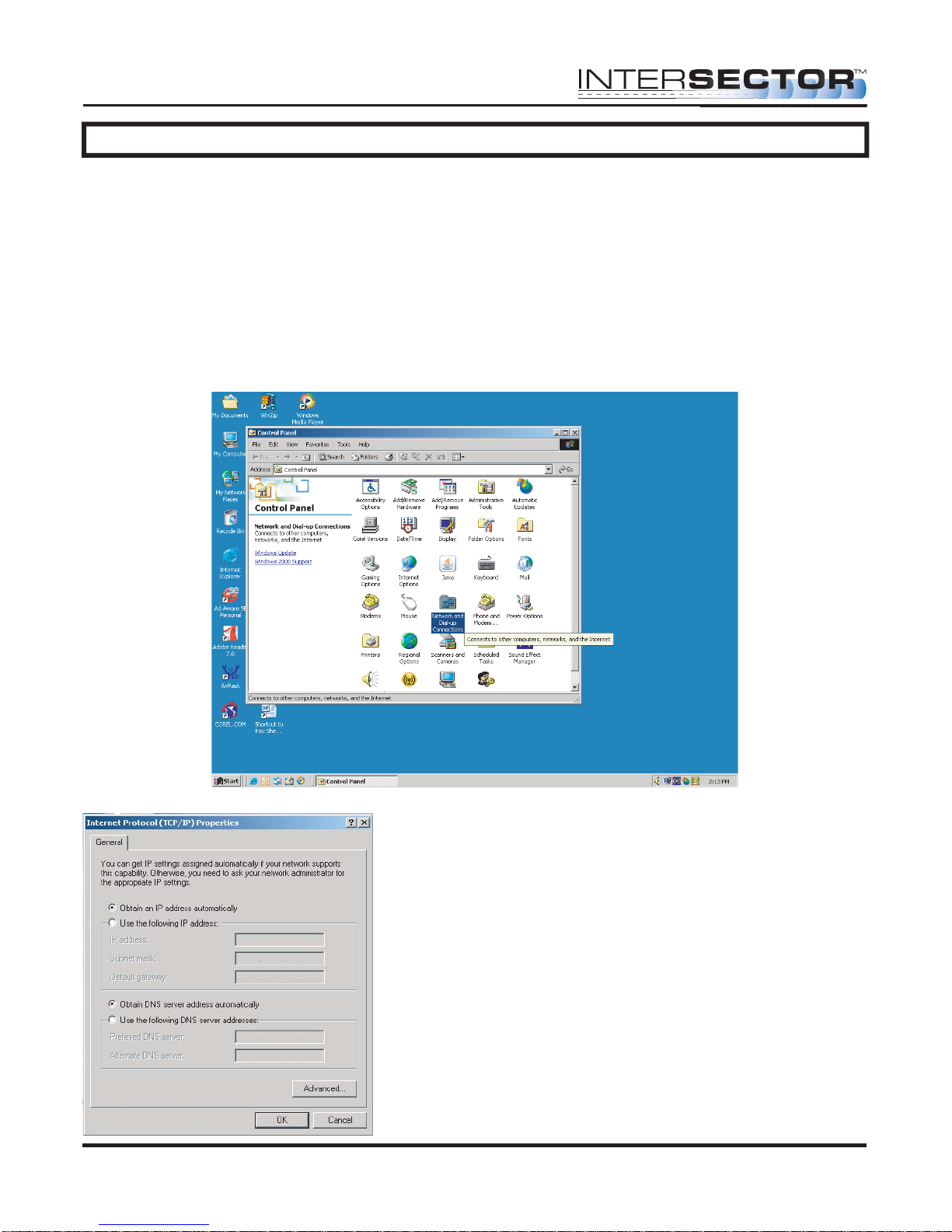
1. Select the START button at the lower left of the computer screen.
2. Select SETTINGS and open CONTROL PANEL.
3. Select NETWORK AND DIAL UP CONNECTIONS (NETWORK AND SHARING
CENTER for Vista, NETWORK AND SHARING for Windows 7).
3b. For Vista, choose MANAGE NETWORK CONNECTION. For Windows 7, select
CHANGE ADAPTER SETTINGS.
4. Select Local Area Network.
5. Click on Internet Protocol TCP/IP (Internet
Protocol version 4TCP/IPV4 for Vista or
Windows 7).
6. Select Properties.
MS Sedco INTERSECTOR Installation Instructions Page 13 INTERSECTOR-1.9Uv092717
Page 14
INTERSECTOR
Microwave Motion and
Presence Sensor Installation Instructions
INSTALLATION (continued)
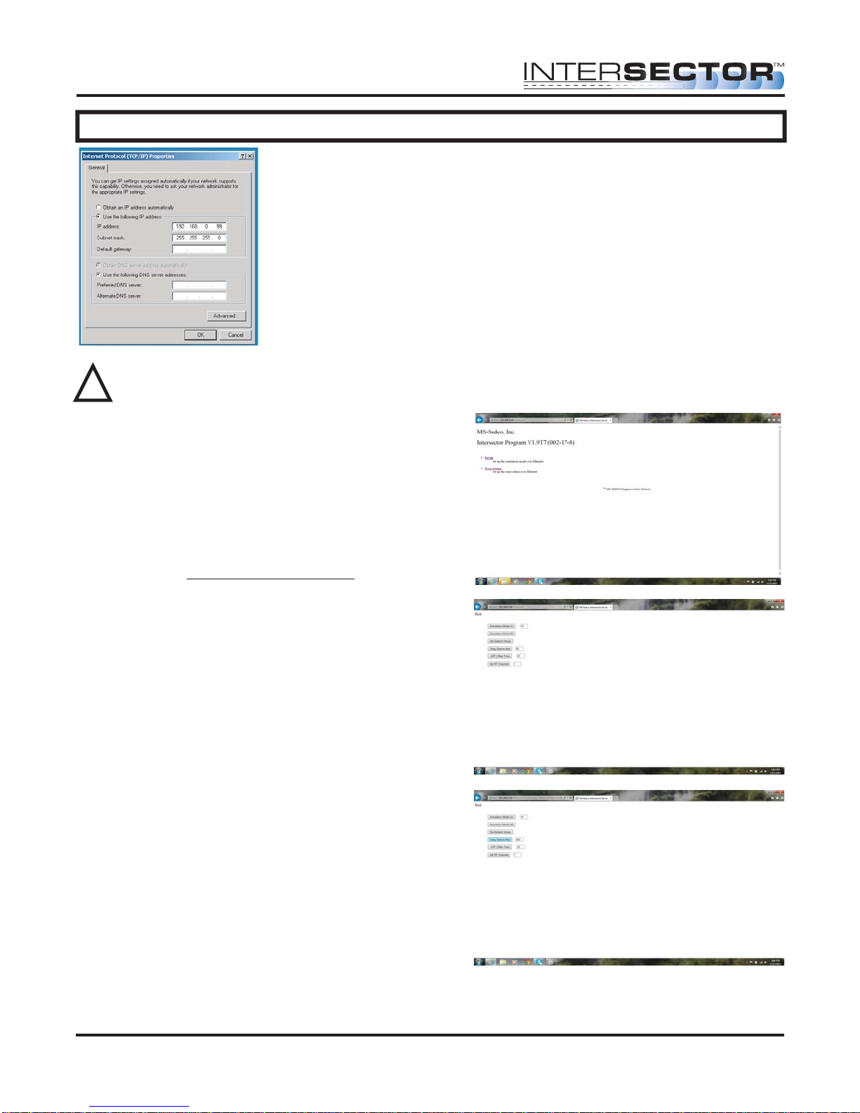
7. Select Use the following IP address.
8. For IP address, enter the following: 192.168.0.99
9. For Subnet Mask enter the following: 255.255.255.0
(NOTE: When you are finished installing the
INTERSECTOR, it will be necessary to return to
Properties and select “Obtain an IP address
automatically” to restore default port settings.)
Click OK to save changes and close the network window.
WARNING: DO NOT REFRESH
!
your internet browser after entering
IP Address. Always enter the IP
Address manually.
Programming The INTERSECTOR:
On your computer, open an Internet browser
(Internet Explorer version 7 or greater is
preferred). In the Address bar of the internet
browser type HTTP://192.168.0.100. This should
connect the computer to the sensor. You will be
prompted for a password. The default password
is “password”. After the password is accepted
the start page for sensor setup will be displayed.
If you wish to change DELAY BEFORE MAX or
OZP/MAX TIME from the default settings,
choose SETUP. Default time for DELAY BEFORE
MAX is 120 seconds. Default time for OZP/MAX
Time is NULL (No value).
Enter the desired value (0 - 960 seconds) in the
window next to DELAY BEFORE MAX. Click on
DELAY BEFORE MAX time to store the RF
Channel Value. Repeat this process for
OZP/MAX TIME. Click BACK to exit the Setup
menu.
To assign an RF Channel to the INTERSECTOR,
enter a number 1-7, then click “Set RF Channel”.
It is recommended that a separate channel
number be assigned to each sensor at an intersection.
MS Sedco INTERSECTOR Installation Instructions Page 14 INTERSECTOR-1.9Uv092717
Page 15
INTERSECTOR
Microwave Motion and
Presence Sensor Installation Instructions
INSTALLATION (continued)
Select ZONE SETTING. This will open the
PROGRAMMING SCREEN for the
INTERSECTOR. (Note: You can enter
dimensions in either FEET or METER by
changing the Unit Select Box. The values
will automatically correct when switching
between FEET or METER.)
Upon entering the PROGRAMMING
SCREEN you will see the TARGET SETUP
TABLE, DATA DISPLAY, and VEHICLE
TABLE.
You will see vehicles passing through the DATA DISPLAY (right half of screen). If you
do not, confirm the alignment of the sensor. To track the pattern of the vehicles being
displayed, turn on BREAD CRUMBS.
MS Sedco INTERSECTOR Installation Instructions Page 15 INTERSECTOR-1.9Uv092717
Page 16

INTERSECTOR
Microwave Motion and
Presence Sensor Installation Instructions
INSTALLATION (continued)
Refer to your completed INTERSECTOR Worksheet and enter the Offset Angle or
dimensions to the center of the stop bar zone. Click on SET SENSOR ORIENTATION to
save the value. This should correctly align the vehicles passing through the stop bar
area on the graphics portion of the screen (right side).
Turn on BREAD CRUMBS by clicking the box in the upper right portion of the screen.
Use the Bread Crumb graphics to ensure that the sensor is aligned properly. If the
BREAD CRUMBS for the left or right turn lane are ending early, adjust the sensor side to
side until the desired tracking is displayed. If the BREAD CRUMBS for the straight
lanes are ending early or extending too far, adjust the tip angle up or down slightly.
Fine tune the offset angle so that the path of vehicles aligns with the vertical lines
displayed. Note that these lines do not represent lanes, but are merely to be used for
alignment purposes. If you are working with a curved road, look for alignment in the
stop bar area only.
SETTING UP DETECTION ZONES:
If this is your first time setting up an INTERSECTOR, you can explore its capabilities in
SIMULATION MODE. Please refer to Appendix A for more information.
The best way to set up detection zones is to base your zones off of real traffic. When a
car is in a desired zone, click the Stop button.
Next, refer to the VEHICLE TABLE and locate the desired ID to copy. The vehicle
number should match what you see in the DATA DISPLAY.
On the Zone Select line of the webpage, choose the zone that you want to set up (Zone 1
is the default). Then choose the ID that you selected in the previous step. Note that this
is the ID number, not the Vehicle number. Then click COPY DATA, and the zone should
appear in the graphics portion of the screen. A stop bar graphic will appear at the front
of Zone 1.
Now it is time to fine tune the zone. To extend the zone farther forward, adjust Y Front
entry (10 feet is the default value). To extend the zone farther back, adjust the Y Behind
value (80 feet is the default value). To widen or narrow your zone, adjust the Width of
Zone entry (12 feet is the default value). If you have adjacent zones, we recommend
leaving no gap between them - even a little overlap is OK. To apply DELAY TIME or
EXTENSION TIME to a zone, enter values for those entries. Next, choose an output by
entering a value for OPTO OUTPUT (0-4). A value of zero will indicate this zone is
turned off. No output will be sent for a vehicle detected within this zone. Finally, enter a
description for the zone for future reference. Check BIKE ONLY to ignore cars and
trucks that may be in the zone.
MS Sedco INTERSECTOR Installation Instructions Page 16 INTERSECTOR-1.9Uv092717
Page 17

INTERSECTOR
Microwave Motion and
Presence Sensor Installation Instructions
INSTALLATION (continued)
If you find that you need to move the overall location of a zone, you can move a zone to
the left by decreasing the X value (note that X values may be negative in some cases).
Increasing the X value will move the zone to the right. Decreasing the Y value will move
the zone closer, while increasing it will move the zone farther away.
The new zone will show in yellow except when a vehicle is present. If a vehicle is
present in a zone, the color changes to red. When you are satisfied with the location of
your zone, click on SET ZONE DATA near the upper left of your screen. At this point,
the yellow zone will turn green, indicating that it is saved to memory. You will also
observe traffic again in the DATA DISPLAY and in the VEHICLE TABLE.
Repeat the previous steps as necessary to create additional zones.
We recommend observing traffic for a short while to observe that all zones are
operating as intended. BREAD CRUMBS may be beneficial for making these
observations. Make any adjustments to the dimensions of the zones if necessary. Any
zones being altered will turn back to yellow instead of green when no vehicle is present.
Click SET ZONE DATA to save your changes.
To save your setup to file, follow these steps:
• Click on SET ZONE DATA to store your setup in the INTERSECTOR
• Select FAVORITES on the Toolbar at the top of your internet browser.
• Select ADD TO FAVORITES, name the setup (possibly the direction of traffic at this
intersection such as Westbound), and create a new folder to store this favorite in,
such as the intersection name (Main and 1st street).
• You can also copy the website link from the address bar and paste it to a Word
document. This Word document can then be saved as a file. We recommend naming
the file with the intersection and direction name (MainFirstWestbound.doc).
When you are satisfied with your settings and ready to enter operational mode, click on
BACK at the upper left. Please note that if you haven’t clicked SET ZONE DATA, one or
more of your changes may not be saved.
MS Sedco INTERSECTOR Installation Instructions Page 17 INTERSECTOR-1.9Uv092717
Page 18

INTERSECTOR
Microwave Motion and
Presence Sensor Installation Instructions
ADJUSTMENTS
Observe the location that the zone is shown on the DATA DISPLAY. If the zone needs to
be moved or resized, use the following guidelines:
• To move the zone left, The X coordinate value should be decreased. If necessary,
the value can be negative. (Example: -38.00)
• To move the zone right, the X coordinate value should be increased.
• To move the zone farther away (up on the screen), the Y coordinate value should
be increased.
• To move the zone closer (down on the screen), the Y coordinate value should be
decreased.
• To make the zone wider or narrower, increase or decrease the value for Width of
Zone.
• Increasing or decreasing the values for Y Front or Y Behind will lengthen or make
the zone shallower.
NOTE: For instructions on saving and loading data using 1.9U software, please refer
to the Addendum at the end of this manual
How to save the data acquired per approach for an intersection.
• First click on SET ZONE DATA. This saves all of the data for that approach of the
INTERSECTOR that you are working with to the address bar at the top of your
browser.
• From the ‘add to favorite’ click on new folder. Name the folder to reflect the
specific Intersection.
• From the ‘add to favorite’ click on the folder that you just made. In the box titled
MS Sedco, type in the approach name of the direction and save. (Example: South
bound 16th and Main)
• If you need to re-install a setup for that approach, go to your Favorites. Select the
desired folder and locate the correct approach. Opening this file will
automatically load the setup information into the INTERSECTOR.
MS Sedco INTERSECTOR Installation Instructions Page 18 INTERSECTOR-1.9Uv092717
Page 19

INTERSECTOR Microwave Motion and
Presence Sensor Installation Instructions
ADJUSTMENTS (continued)
OPERATIONAL MODE:
Unplug the Laptop Ethernet cable from the Laptop Ethernet Port. Move the Sensor
Ethernet cable to the Operational Ethernet port. The green LED indicating connection
and the yellow LED indicating data should be on. The 2 or 4 LED for outputs will turn
off when a valid connection has been established to the sensor. Confirm operation of
each zone. Ensure that the appropriate LED light up when detection occurs.
Software versions 1.9S and newer include features that were not available in earlier
versions. These include:
• Ability to configure up to 8 outputs using two (2) TCIB connected as Primary and
Secondary units.
• Ability to remove zones from crosswalk area to avoid pedestrian detection.
• Ability to enable Collision Avoidance feature for zones in potentially dangerous
areas.
• Ability to detect vehicles traveling in the wrong direction through zones.
DEFINITIONS:
OUTPUT UPGRADE:
Allows the configuration of up to 8 outputs using both a Primary and Secondary TCIB.
TAIL EXTENSIONS:
Allows the end user to remove the zone from the crosswalk to avoid pedestrian
detection that might cause a false call.
WRONG WAY DETECTION (DEPARTING TRAFFIC DETECTION):
Enables the detection of vehicles traveling in the wrong direction in a lane, or entering
on/off ramps. This option can be also used to detect traffic in departing lanes.
COLLISION AVOIDANCE/ SPEED BINS:
The Collision Avoidance feature, based on a new direction from the FHWA, allows the
user to set up zones with speed values. In the event a vehicle exceeds that speed while
in the zone an output is provided to the controller to extend the Collision Avoidance
system. These Speed Bins can then be set up to activate an advanced warning system
as vehicles are approaching dangerous curves or work zones at excessive speeds.
MS Sedco INTERSECTOR Installation Instructions Page 19 INTERSECTOR-1.9Uv092717
Page 20

INTERSECTOR
Microwave Motion and
Presence Sensor Installation Instructions
ADJUSTMENTS (continued)
SET-UP INSTRUCTIONS:
Eight Output Setup
1. Equipment needed:
a. Two TCIB cards
b. HyperTerminal (this can be downloaded from our website or elsewhere on the
Internet)
c. One RS232 Dongle (this connects the laptop to the TCIB)
d. A powered rack
e. A laptop or desktop computer
f. One RS232 jumper cable male to male null modem type
2. HyperTerminal settings are 115, 200, 8, N, 1.
3. Connect the RS232 Dongle.
4. Engage HyperTerminal.
5. Power on the Rack and the TCIB boards.
6. HyperTerminal will display messages; one will show the software version of the
TCIB. Software version must be 1.3S or higher to enable new features.
7. Select Type. Enter Primary or Secondary and the TCIB will begin programming.
Once finished, mark each card as either a Primary or Secondary.
Note: All TCIB are shipped as Primary.
8. Connect the Primary TCIB to Secondary TCIB with the RS232 jumper cable
provided.
9. Power the INTERSECTOR that will be using the 8-Output system.
10. At the main screen, confirm the software version of the INTERSECTOR is 1.9S or
higher, to enable the new feature.
11. Select Zone Settings.
12. Configure zones 1-8.
MS Sedco INTERSECTOR Installation Instructions Page 20 INTERSECTOR-1.9Uv092717
Page 21

INTERSECTOR
Microwave Motion and
Presence Sensor Installation Instructions
ADJUSTMENTS (continued)
Tail Extensions Setup
1. Equipment needed: None
2. Once the INTERSECTOR is in Setup Mode, proceed to Zone Settings. Set up the
zones where extension is needed (generally the right turn and stop bar lanes).
3. Start the configure format by selecting Configure.
4. While in configure, check the Extend box for each required zone.
5. Once all zones needing extension are selected, click on Set Configure.
6. Watch the zones to verify proper operation.
7. Return to Operational Mode.
Collision Avoidance and Speed Bin Setup
1. Equipment needed: None
2. With the INTERSECTOR in Setup Mode, proceed to Zone Settings. Set up the zones
where Collision Avoidance or Speed Bin is needed (generally these will be set behind
the stop bar zones).
3. Start the configure format by selecting Configure.
4. While in configure, enter values for minimum and maximum speeds for each zone
being used as a Speed Bin for Collision Avoidance. Once all speed ranges have
been set, click on Set Configure.
5. Watch the zones to verify proper operation.
6. Return to Operational Mode.
MS Sedco INTERSECTOR Installation Instructions Page 21 INTERSECTOR-1.9Uv092717
Page 22

INTERSECTOR
Microwave Motion and
Presence Sensor Installation Instructions
ADJUSTMENTS (continued)
Collision Avoidance and Speed Bin Setup (continued)
Wrong Way Detection Setup
1. Equipment needed: None
2. With the INTERSECTOR in Setup Mode, proceed to Zones Settings. Set up the zones
where Wrong Way Detection is needed (it is recommended they be located behind
the stop bar zones).
3. Start the configure format by selecting Configure.
4. While in configure, select Wrong Way Detection for each zone needing this feature,
click on Set Configure
5. Watch the zones to verify proper operation. This feature may be difficult to confirm.
Use extreme caution if using a test vehicle.
6. Return to Operational Mode.
MS Sedco INTERSECTOR Installation Instructions Page 22 INTERSECTOR-1.9Uv092717
Page 23

INTERSECTOR Microwave Motion and
Presence Sensor Installation Instructions
CHANGING THE INTERSECTOR IP ADDRESS
Software for the INTERSECTOR and TCIB has been updated to allow the system to be IP
addressable. Any INTERSECTOR units shipped with rev K or later software are IP
addressable. Older units that have rev F software must be upgraded to be IP
addressable. For instructions on updating software, please contact MS Sedco.
WARNING: If you plan to change IP Addresses on the INTERSECTOR and TCIB
!
for use with a local network, please maintain a record of the new IP Addresses
and passwords. If you do not have access to the IP Addresses and passwords it
will be necessary to connect to the INTERSECTOR and TCIB to obtain this
information.
WARNING: If you are setting up an Ethernet switch or multi-port hub to access
!
the INTERSECTOR it is important to use a modified Ethernet cable between the
“Operational” port of the TCIB and the switch or hub. This cable should be
modified to ensure voltage is not transmitted to the switch or hub. Ethernet
Switch Safe cable is available from MS Sedco. To construct one of the cables it
is necessary to disable pins 4, 5, 7, and 8.
To change the IP addresses on the INTERSECTOR or TCIB, it is first necessary to know
the current IP addresses. The default IP Addresses are:
Default Addresses:
INTERSECTOR IP 192.168.0.100
TCIB card 192.168.0.98
TCIB gateway 192.168.0.1
Computer 192.168.0.99
Computer subnet mask 255.255.255.0
Computer Gateway 192.168.0.1
To find out which version of software the INTERSECTOR and TCIB has, follow these
instructions:
To verify the software version of the INTERSECTOR:
• Set laptop IP address to 192.168.0.99 in the LAN properties of the TCP/IP as shown
on pages 11 and 12 of the INTERSECTOR Installation Instructions. Connect laptop to
the TCIB “Laptop” port. Move INTERSECTOR Ethernet cable from “Operational” port
to “Setup” port. Access the default web page at address 192.168.0.100. Note that
if your sensor has rev K or later software, you will be prompted for a password.
The default password is “password”. The software version should be shown as
v1.9T, where T is the software revision. NOTE: If IP Addresses have previously been
changed, it will be necessary to use the new IP addresses to access the
INTERSECTOR.
MS Sedco INTERSECTOR Installation Instructions Page 23 INTERSECTOR-1.9Uv092717
Page 24

INTERSECTOR
Microwave Motion and
Presence Sensor Installation Instructions
CHANGING THE INTERSECTOR IP ADDRESS (cont.)
To verify the software version of the TCIB:
• Connect the laptop to TCIB RS232 port. This can be accomplished by using a USB to
RS232 adaptor. Using the communications program Hyperterminal, which is
supplied with Windows up to version XP, you can connect to the TCIB. If you are
using Windows 7 you can obtain a version of Hyperterminal on the internet. For
instructions on using Windows 7, please refer to Appendix C at the back of this
manual.
• Open Hyperterminal by clicking on “Start” at the bottom right of your screen. Select
“Programs” then “Accessories” and then “Communications”. Hyperterminal should
be listed there.
MS Sedco INTERSECTOR Installation Instructions Page 24 INTERSECTOR-1.9Uv092717
Page 25

INTERSECTOR
Microwave Motion and
Presence Sensor Installation Instructions
CHANGING THE INTERSECTOR IP ADDRESS (cont.)
Once you have opened Hyperterminal you must configure it for use with the TCIB or
INTERSECTOR. You can either create a new connection when prompted, or you can
select “File” then “Properties”. Select the COM port the RS232 is connected to on your
laptop and select “Configure”. Enter the following settings:
Bits per second: 115200
Data Bits: 8
Parity: None
Stop Bits: 1
MS Sedco INTERSECTOR Installation Instructions Page 25 INTERSECTOR-1.9Uv092717
Page 26

INTERSECTOR
Microwave Motion and
Presence Sensor Installation Instructions
CHANGING THE INTERSECTOR IP ADDRESS (cont.)
Once you have configured Hyperterminal you can connect to the TCIB by clicking the
reset button on the TCIB or powering the TCIB while Hyperterminal is running. If you
connect to the TCIB you can see this screen:
The bottom line from the Hyperterminal screen shows the TCIB software as version
1.3S. The screen also shows the IP address for the TCIB. Record this value for use in
the next section.
Checking or setting IP Address
To check or set IP addresses you need to use a software program called
IP_Address_Set.exe. This program is available by contacting MS Sedco direct. 00
There are several steps to changing the IP addresses on the INTERSECTOR, TCIB, and
laptop. The steps would be:
• Confirm IP addresses in each device. Record these values for later use.
• Set up the TCP/IP on your computer as shown on pages 11 and 12 of this manual.
• Connect to the TCIB via RS232 cable.
• Change TCIB IP address using the IP_Address_Set program.
• Connect to the INTERSECTOR via Ethernet cable.
• Use the IP_Address_Set program to change INTERSECTOR IP address
• Verify that changes match between INTERSECTOR and TCIB.
MS Sedco INTERSECTOR Installation Instructions Page 26 INTERSECTOR-1.9Uv092717
Page 27

INTERSECTOR Microwave Motion and
Set-up
Presence Sensor Installation Instructions
CHANGING THE INTERSECTOR IP ADDRESS (cont.)
• Confirm you can access this address by opening the webpage using the new IP
address.
To confirm or set the IP address on the TCIB, connect the laptop to the TCIB via RS232.
Connect the laptop to the laptop port of the TCIB via Ethernet cable. Connect the
INTERSECTOR Ethernet cable to the Setup port of the TCIB. You can also connect to the
INTERSECTOR and TCIB via Ethernet switch or hub. The INTERSECTOR should be
connected to the TCIB Setup port via Ethernet cable, and the TCIB Operational port
should be connected to the Ethernet switch or Hub.
TCIB card
Ethernet
Switch
Laptop
Operational
INTERSECTOR
HOST
Ethernet
cables
Laptop
WARNING: Ensure that the TCIB “Operational” port is connected to the Ethernet
!
switch or hub with the cable labeled “Ethernet Switch Safe” or that the cable has
been modified to disable voltage lines.
WARNING: If you are setting up an Ethernet switch or multi-port hub to access
!
the INTERSECTOR it is important to use a modified Ethernet cable between the
“Operational” port of the TCIB and the switch or hub. This cable should be
modified to ensure voltage is not transmitted to the switch or hub. Ethernet
Switch Safe cable is available from MS Sedco. To construct one of the cables it
is necessary to disable pins 4, 5, 7, and 8.
Open the default webpage (192.168.0.100) and note you are challenged with a password.
Run “IP_Address_Set.exe”. On the INTERSECTOR tab under the Connection Select
mark “Internet” since you are connecting via Ethernet cable. Ensure that the correct
INTERSECTOR IP Address is shown in the box next to the “Connect Internet” button.
Click on the “Connect Internet” button. A message will be displayed to show you are
now connected to the INTERSECTOR.
MS Sedco INTERSECTOR Installation Instructions Page 27 INTERSECTOR-1.9Uv092717
Page 28

INTERSECTOR
Microwave Motion and
Presence Sensor Installation Instructions
CHANGING THE INTERSECTOR IP ADDRESS (cont.)
To retrieve a misplaced password:
Select “Read Password”. When the password is read, the program will display the
message “Read Password Finished”.
To confirm TCIB IP address:
Refer back to the IP address from Hyperterminal in the previous section. If you need to
confirm IP address again, connect laptop to TCIB via RS232 cable. Run Hyperterminal or
use IP_Address_Set to access the TCIB. If using IP_Address_Set select the TCIB tab.
Select the COM port that corresponds to the RS232 cable. Select “Read IP Address”.
The IP address for the TCIB should be displayed.
To change INTERSECTOR IP Address:
When changing IP Address it is first necessary to determine the new addresses to be
used. For an example, we will use the following IP Addresses:
The new addresses we want to change to are:
INTERSECTOR IP 10.230.39.230
TCIB card 10.230.39.231
Gateway 10.230.32.1
Computer 10.230.32.51
Computer subnet mask 255.255.240.0
Gateway 10.230.32.1
MS Sedco INTERSECTOR Installation Instructions Page 28 INTERSECTOR-1.9Uv092717
Page 29

INTERSECTOR
Microwave Motion and
Presence Sensor Installation Instructions
CHANGING THE INTERSECTOR IP ADDRESS (cont.)
To set the IP Address on the INTERSECTOR, connect the laptop to the laptop port of
TCIB and the INTERSECTOR to “Setup” port of the TCIB, both via Ethernet cables. You
can also connect to the INTERSECTOR via Ethernet switch or hub. The INTERSECTOR
should be connected to the TCIB “Setup” port, and the TCIB “Operational” port should
be connected to the Ethernet switch or hub.
TCIB card
CLIENT
Operational
Sensor
Laptop
INTERSECTOR
HOST
Ethernet
Switch
Laptop
Run IP_Address_Set. You should see the following screen:
Ethernet
cables
MS Sedco INTERSECTOR Installation Instructions Page 29 INTERSECTOR-1.9Uv092717
Page 30

INTERSECTOR
Microwave Motion and
Presence Sensor Installation Instructions
CHANGING THE INTERSECTOR IP ADDRESS (cont.)
Enter the new IP address, Subnet Mask, and Gateway address, then click “Set IP
Address”.
The next step is to set the IP address for the TCIB via the RS232 cable. With the TCIB
connected to the laptop via the RS232, run IP_Address_Set. Choose the TCIB tab and
select the correct Comm Port. Click “Read IP Address”. Change the information in
boxes to reflect the new IP address, Subnet Mask, Gateway address, and INTERSECTOR
IP address. Click “Set IP Address” and wait until the message “Set IP Address Finished”
is displayed.
10 230 39 231
255 255 240 0
10 230 32 1
10 230 39 230
MS Sedco INTERSECTOR Installation Instructions Page 30 INTERSECTOR-1.9Uv092717
Page 31

INTERSECTOR
Microwave Motion and
Presence Sensor Installation Instructions
CHANGING THE INTERSECTOR IP ADDRESS (cont.)
After changing the IP address you must setup your laptop for this gateway:
Verify the setup by connecting to the INTERSECTOR via the new IP address:
10 230 39 230
255 255 240 0
10 230 32 1
10.230.39.230
MS Sedco INTERSECTOR Installation Instructions Page 31 INTERSECTOR-1.9Uv092717
Page 32

INTERSECTOR
Microwave Motion and
Presence Sensor Installation Instructions
MAINTENANCE
No regular maintenance of the INTERSECTOR is required. During the installation and
setup of the INTERSECTOR, certain problems may occur. We have attempted to list
some common problems and possible solutions. If you need further assistance while
installing the INTERSECTOR, please contact MS Sedco Technical Support at (317)
842-2545.
DESCRIPTION OF
PROBLEM
When the TCIB card is
plugged in the LED
lights do not light up:
LED lights are always
on:
Unable to see setup
page when computer is
connected:
SOLUTION
• Check for power to the TCIB board.
• Verify that traffic is present in detection zones. Move
Ethernet cable to setup port. Connect PC and verify
zone location and sensor aim.
• Prior to completion of setup the TCIB board will keep
LED lights on as a “constant call”. Ensure that Ethernet
cable is connected to operational port. Connect sensor
to computer and setup zones.
• Check to ensure that Ethernet cable is connected to
sensor
• Check to ensure that Ethernet cable is plugged into
Setup port and laptop is connected to laptop port of the
TCIB board
• With the INTERSECTOR installed and connected to your
PC the Ethernet LEDs on the PC should show
connection. One LED is connection and should stay on,
and the other is data which should blink.
• Ensure that laptop IP address is set to proper address
(as detailed on Page 7 of installation manual)
• Check LEDs on the TCIB card. If they are not on, the
TCIB card is not functioning.
• Check the Ethernet cable. Plug the cable from the sensor
into the operational Ethernet port on the TCIB and see
that the LEDs go out to ensure the sensor is functioning
properly and there is Ethernet communication.
Once Ethernet
connection is made, and
you see the Zone Setup
page on your PC you see
a message at the top of
the page that reads
“Sensor Error”:
MS Sedco INTERSECTOR Installation Instructions Page 32 INTERSECTOR-1.9Uv092717
• There is a problem with the sensor that cannot be
corrected in the field. Contact your distributor or MS
Sedco for further information.
Page 33

INTERSECTOR Microwave Motion and
Presence Sensor Installation Instructions
MAINTENANCE
DESCRIPTION (CONT.)
Unable to detect any
vehicles during setup
process:
Random numbers are
being displayed in your
browser:
There are errors in
numbers displayed in
your setup windows:
Settings are not being
saved properly:
Vehicles occasionally
pass through zone
undetected:
SOLUTION (CONT.)
• Put unit in SIMULATION MODE to verify sensor operation.
• Adjust aim of sensor. Sensor should be pointed toward
the center of desired detection area and angled down
slightly (2-3º typical).
• Exit current Internet Explorer window and open a new
window.
• Go to Setup Menu and click on SET DEFAULT VALUES.
• Make sure to wait on web pages to load fully before
trying to save settings. Before clicking on additional
buttons, ensure that current operations are completed.
• Edit software ZONE SETTINGS. Lengthen ZONE
SETTINGS to properly match desired detection areas.
• Confirm that LEDs come on as expected when vehicles
pass through the zones. Note that if the zone is set
short, fast cars can “jump” over the zone due to the
sample rate of the sensor (20 times per second).
Vehicles continue to be
shown after they have
departed:
MS Sedco INTERSECTOR Installation Instructions Page 33 INTERSECTOR-1.9Uv092717
• Adjust aiming of sensor to ensure that it is centered and
tilted down at a slight angle.
Page 34

INTERSECTOR
3
3
Microwave Motion and
Presence Sensor Installation Instructions
PARTS LIST
• TC-CK1-SBE sensor
• TCIB 2.1 2-output single-slot interface board
• TCIB 4.1 4-output single-slot interface board
• TCIB 4.2 4-output two-slot interface board
ELECTRICAL INTERCONNECTION DETAILS & DRAWINGS
Rear panel
interface IP67 Ethernet
TCIB Card in DETECTOR RACK
Four Phase
Green
Inputs
Four
Status
Outputs
Four
Outputs
Ethernet
RS232
Ethernet
setup &
laptop
Visual
display
represents
each Opto
connector
Ethernet
cable with
power to
sensor
NEMA
card rear
panel
interface
2
Ethernet
Visual display
represents each
2
OPTO OUTPUT.
Model for 2 and 4
outputs.
Sensor
mounted on
traffic pole
Schematics will be supplied to governmental entities as required.
Assembly drawings will be supplied to governmental entities as required.
MS Sedco INTERSECTOR Installation Instructions Page 34 INTERSECTOR-1.9Uv092717
SCHEMATICS
ASSEMBLY DRAWINGS
Page 35

INTERSECTOR
Microwave Motion and
Presence Sensor Installation Instructions
APPENDIX A: SIMULATION MODE
SIMULATION MODE can be used to demonstrate the INTERSECTOR, confirm proper
installation, or learn how to set up zones and use features. For first-time INTERSECTOR
installers, SIMULATION MODE can be used to gain an understanding of the sensor
setup and some of the sensor’s operating characteristics.
To enter SIMULATION MODE, follow these steps:
Start with MAIN PAGE.
1. Click on SETUP.
2. Enter 1 for SIMULATION MODE ON and click on SIMULATION MODE ON. This
enables SIMULATION MODE.
3. Click on BACK.
4. Click on ZONE SETTING. When this page loads you will see one vehicle pass
through the grid.
a. Note the ID of the object increments by one each time.
b. Vehicles are sequentially numbered from 0 to 63 and then the numbering loops
back to 0.
c. You can STOP the display to copy X and Y locations to any Zone. Vehicle
tracking is fully working while the display is stopped.
d. You can set up a zone for this object manually. Note the zone turning yellow
when you change any parameter on the zone. You must click on SET ZONE
DATA or any changes are lost.
e. To use AUTO DETECT click on the check box when the vehicle is at the top of
the grid. Note that as it goes through the stop bar the screen will freeze and
update the angle. It will stay at zero since the vehicle is going vertically. The
number 20 is the distance in front and behind the stop bar which
INTERSECTOR uses to calculate and correct for angle of travel of cars. In
other words it looks at Y =120 and Y=80 and using the X value for each point
determines the offset angle to make cars go through straight. The value 20
can be reduced or increased but this is a good starting point. 10 may work
better for smaller intersections.
f. The zone will begin working when you enter the X dimension for this vehicle.
Note it is typically -16 feet for Zone 1. Enter this number (-16) for Zone 1 X cell.
Click on SET ZONE DATA. Note the vehicle will go through the center of the
zone now and Zone 1 counter will increment each time the vehicle goes
through the zone. OPTO OUTPUT 1 will also turn red indicating detection.
5. Go back to SIMULATION MODE ON and enter 16. Click on back and then click on
ZONE SETTING.
6. Now you will see 16 vehicles going through the grid. NOTE: in SIMULATION
MODE, Delay Before Max Time is not valid and the objects stay on the screen
forever.
7. Now we will shift the grid to show how to center the vehicles and then expand the
grid to see zones in detail. Enter 100 for Move Left Or Right. Note the screen
shifts right. The grids shift right also.
MS Sedco INTERSECTOR Installation Instructions Page Appendix A-1
Page 36

INTERSECTOR
Microwave Motion and
Presence Sensor Installation Instructions
APPENDIX A: SIMULATION MODE (CONT.)
8. Check BREAD CRUMBS. Note the crumbs left as each car travels through.
Uncheck and the crumbs disappear.
9. Open drop box for FEET and METRIC and chose METRIC. Note all dimensions
have been changed to metric. If you save in metric and then go back to English
you may have rounding errors (e.g. 100 feet will become 99.99).
10. Note the clock. This is an hour meter for INTERSECTOR. Time is saved every 30
minutes. If you unplug before 30 minutes it resets to zero again. If you unplug at
31 minutes it will reset to 31 minutes.
11. To add a second zone use Zone 2 and enter 2 for OPTO OUTPUT. Enter 16 for X to
center this zone on one lane of cars. Click on SET ZONE DATA. Note zone 2 is
active and OPTO OUTPUT 2 is active. Click on SET ZONE DATA to store this text.
12. Typical set up for a zone would be to overlap side by side zones by 1 foot. Adjust
the WIDTH OF ZONE to get 1 foot overlap. The overlap is visible as darker area.
If a vehicle enters that area both Zones will be activated.
13. To copy data, click on STOP. The vehicles will stop on the display but moving
vehicles are still being tracked. Set ZONE SELECT to 3. Select ID to any vehicle
you would like to set a zone at. Note that the ID number is different from the
Vehicle number, which appears in the second column and in the chart. Note the X
and Y position of this ID and then click on COPY DATA. Those X and Y values are
now in the table. Set OPTO OUTPUT for zone 3 to 4. Click on START. Now you
have created a new zone that will activate OPTO OUTPUT 4. To take the unit back
to its initial settings, go to MAIN MENU, click on SETUP, then click on SET
DEFAULT VALUES. Upon returning to ZONE SETTING, all values should be back
to factory settings.
14. When finished, click on BACK, then on SETUP, then on SIMULATION MODE OFF.
MS Sedco INTERSECTOR Installation Instructions Page Appendix A-2 INTERSECTOR-1.9Uv092717
Page 37

INTERSECTOR Microwave Motion and
Presence Sensor Installation Instructions
APPENDIX B: TCIB Connections
TCIB Pin Out (Blue active)
Pin Function Pin Function
A .................. DC (-) ........................................... 1...................Chl. 1 Phase Green Input
B.................. DC (+) .......................................... 2...................Chl. 2 Phase Green Input
C.................. Reset Input ................................. 3 ...................Chl. 3 Phase Green Input
D.................. Chl. 1 Loop Input........................ 4 ...................Chl. 1 Loop Input
E .................. Chl. 1 Loop Input........................ 5...................Chl. 1 Loop Input
F.................. Chl. 1 Out Drain.......................... 6...................No Connection
H.................. Chl. 1 Out Source....................... 7...................Chl. 1 TS 2 Status Output
J .................. Chl. 2 Loop Input........................ 8 ...................Chl. 2 Loop Input
K.................. Chl. 2 Loop Input........................ 9 ...................Chl. 2 Loop Input
L .................. Chassis Ground ......................... 10 .................Chl. 4 Phase Green Input
M.................. No Connection ........................... 11 .................No Connection
N.................. No Connection ........................... 12 .................No Connection
P..................Chl. 3 Loop Input........................ 13.................Chl. 3 Loop Input
R.................. Chl. 3 Loop Input........................ 14 .................Chl. 3 Loop Input
S .................. Chl. 3 Out Drain.......................... 15 .................No Connection
T.................. Chl. 3 Out Source....................... 16.................Chl. 3 TS 2 Status Output
U.................. Chl. 4 Loop Input........................ 17 .................Chl. 4 Loop Input
V.................. Chl. 4 Loop Input........................ 18.................Chl. 4 Loop Input
W................. Chl. 2 Out Drain.......................... 19.................No Connection
X .................. Chl. 2 Out Source....................... 20 .................Chl. 2 TS 2 Status Output
Y.................. Chl. 4 Out Drain.......................... 21 .................No Connection
Z ..................Chl. 4 Out Source....................... 22 .................Chl.4 TS 2 Status Output
MS Sedco INTERSECTOR Installation Instructions Page Appendix B INTERSECTOR-1.9Uv092717
Page 38

INTERSECTOR Microwave Motion and
Presence Sensor Installation Instructions
APPENDIX C: Windows 7 Set-up
To complete Windows 7 Set-up, follow these steps:
• Select “Start” in the lower left corner of Windows 7.
• Select “Control Panel”.
• Select “Network and
Sharing Center”.
• Select “Change
Adaptor Settings”.
MS Sedco INTERSECTOR Installation Instructions Page Appendix C INTERSECTOR-1.9Uv092717
Page 39

INTERSECTOR Microwave Motion and
Presence Sensor Installation Instructions
APPENDIX C: Windows 7 Set-up
• Right click on
“Local Area
Connections”.
• Select “Properties”.
• Select “Internet
Protocol 4 (Vers. 4).
• Select “Properties”.
MS Sedco INTERSECTOR Installation Instructions Page Appendix C INTERSECTOR-1.9Uv092717
Page 40

INTERSECTOR Microwave Motion and
Presence Sensor Installation Instructions
APPENDIX C: Windows 7 Set-up
• Select “Use the
following IP Address”
and type in
(192.168.0.99).
• The Subnet Mask will
automatically fill in
the correct address.
• Click “OK” to save
setup.
MS Sedco INTERSECTOR Installation Instructions Page Appendix C INTERSECTOR-1.9Uv092717
Page 41

INTERSECTOR Microwave Motion and
Presence Sensor Installation Instructions
INTERSECTOR1.9U SOFTWARE ADDENDUM
This addendum details changes to the INTERSECTOR features that are dependent on
the following conditions:
• TC-CK1-SBE main board
software is upgraded to
1.9U
• Radar firmware upgraded to
229-05-8
• TCIB software upgraded to
1.4S
TC-CK1-SBE 1.9U UPDATES
There are five key features that change in the 1.9U software:
1. Rain Failsafe
2. Automated OZP
3. Zone Clear Feature
4. Save and Load Zone Data
5. Bicycle Classification Sensitivity
EXPLANATION OF CHANGES
Rain Failsafe
The 1.9U version of
INTERSECTOR software
calculates a Rain Intensity Factor
by counting the number of
raindrops detected within the
first 10 feet of the radar’s view
and measuring the size of the
drops. The Rain Intensity Factor
and Rain Flag are displayed on
the Zone Settings page above
the grid. As shown in Figure 1,
Rain Intensity Factor is the first
number.
Figure 1
MS Sedco INTERSECTOR Installation Instructions Page Addendum-1 INTERSECTOR-1.9Uv092717
Page 42

INTERSECTOR Microwave Motion and
Presence Sensor Installation Instructions
EXPLANATION OF CHANGES (CONTINUED)
Rain Failsafe (continued)
If this exceeds the Rain Counter
Threshold, which can be found and
adjusted on the Setup page, as shown
in Figure 2, the message “RAIN” is
displayed just to the right of Rain
Intensity Factor. When this happens, the
INTERSECTOR and associated TCIB(s)
will go into RECALL. This will continue
until the Rain Intensity Factor has
dropped below the Rain Counter
Threshold and remains there for 5
minutes.
The Default setting for Rain Counter
Threshold is 1000, which specifies
heavy rainfall, as shown on the graph in
Figure 3. Blowing winds that cause rain
to be directed at the INTERSECTOR
could also affect the Rain Intensity
Factor. Increasing the Rain Counter
Threshold will decrease sensitivity to
rain. Decreasing the Rain Counter
Threshold will increase rain sensitivity.
The maximum accepted value is 5000.
To disable rain detection, set the Rain
Counter Threshold to 5000.
Figure 2
MS Sedco INTERSECTOR Installation Instructions Page Addendum-2 INTERSECTOR-1.9Uv092717
Figure 3
Page 43

INTERSECTOR Microwave Motion and
Presence Sensor Installation Instructions
EXPLANATION OF CHANGES (CONTINUED)
Automated OZP
In previous versions of INTERSECTOR software, a timer called Delay Before Max (DBM)
is assigned to a vehicle once it stops moving. The stopped vehicle is held in its last
reported position until its DBM timer expires, or the vehicle moves. If a vehicle stops in
the zone, the DBM timer will begin counting down. Should this same vehicle move, the
DBM timer will reset to its original max value. If the vehicle stops again, the DBM timer
would begin counting down again. In addition to DBM, the INTERSECTOR utilizes a
second timer, Occlusion Zone Protection (OZP), that is applied to the last vehicle in a
zone, when its DBM timer has expired or it disappears from detection due to occlusion.
In the 1.9U version of INTERSECTOR software, the user can change how stopped or
occluded vehicles are processed. By clearing the OZP / Max Time value on the Setup
page, if an OZP event happens (vehicle is occluded) to the last vehicle in a zone, the
remaining time on the DBM timer for the vehicle is assigned to OZP and the vehicle is
held at its last position until time expires, or the vehicle begins moving again. The
default value for DBM is 120, and the default value for OZP / Max Time is null (no value).
If a value is entered in the OZP/Max Time field, the unit will operate as it did in previous
software versions.
Figure 4
MS Sedco INTERSECTOR Installation Instructions Page Addendum-3 INTERSECTOR-1.9Uv092717
Page 44

INTERSECTOR Microwave Motion and
Presence Sensor Installation Instructions
EXPLANATION OF CHANGES (CONTINUED)
Automated OZP (continued)
In addition to these
changes, the DBM timer
setting for a stopped
vehicle is now displayed
on the Zone Setting page,
in the Vehicle Table. When
a vehicle is stopped, its
classification field is
changed to the remaining
DBM timer value. Once the
vehicle speed is greater
than 0, the classification
field will switch back, as
shown in Figure 5.
Figure 5
Zone Clear Feature
The new Clear feature
allows the user to set
automatic timing for
clearing hung vehicles as
traffic begins to move. The
INTERSECTOR will track
vehicles as they begin to
leave the detection zones.
Once a vehicle has moved
10 feet past the front edge
of the zone, the value in
the “Set Clear Time” field
will begin counting down.
Any vehicles that did not
reach the “Clear Speed” once the front vehicle has departed will be cleared after the
timer has expired. Both the “Set Clear Time” and “Clear Speed” fields are configurable
on the Setup page, as shown in Figure 6. Default value for “Set Clear Time” is 1.0
seconds. Default value for “Clear Speed” is 2.0 mph. Ranges for these fields are from
0.0 to 10.0. To disable this feature, set “Set Clear Time” to 0.
Figure 6
MS Sedco INTERSECTOR Installation Instructions Page Addendum-4 INTERSECTOR-1.9Uv092717
Page 45

INTERSECTOR Microwave Motion and
Presence Sensor Installation Instructions
EXPLANATION OF CHANGES (CONTINUED)
Save and Load Zone Data
The Save and Load Zone Data feature allows the user the ability to store and retrieve
INTERSECTOR setup and Zone setting data. When the Save Zone Data button is
selected, a text file containing the current values from the Setup and Zone Settings
pages will be downloaded to the computer. Selecting Load Zone Data will allow the user
to navigate to a location that contains previous save files, using the browser window
that appears. Selecting a file and clicking OK will load the saved values into the Setup
and Zone Settings pages.
NOTE: Internet Explorer and Microsoft Edge will occasionally fail during upload.
!
Google Chrome and Mozilla Firefox are recommended web browsers for using the
Load Zone Data feature.
The interface to Save Zone Data files will depend upon the web browser being used, and
which settings are selected. The following sections provide details for using the Save
and Load Zone Data feature with the four web browsers previously mentioned.
Figure 7
MS Sedco INTERSECTOR Installation Instructions Page Addendum-5 INTERSECTOR-1.9Uv092717
Page 46

INTERSECTOR Microwave Motion and
Presence Sensor Installation Instructions
EXPLANATION OF CHANGES (CONTINUED)
Google Chrome
When using Google Chrome, anything downloaded by
selecting “Save Zone Data” will be automatically saved
to the “Downloads” folder. Without changing any
Chrome settings, saved data will be represented as
shown in Figure 8.
Figure 8
To customize file name and save locations, click on the
“Customize and control Google Chrome” menu, and
click “Settings” as shown in Figure 9.
Figure 9
MS Sedco INTERSECTOR Installation Instructions Page Addendum-6 INTERSECTOR-1.9Uv092717
Page 47

INTERSECTOR Microwave Motion and
Presence Sensor Installation Instructions
EXPLANATION OF CHANGES (CONTINUED)
Google Chrome (continued)
When the new window opens, select
“Settings” at the upper left, click on
“Advanced” and select “Downloads” as
shown in Figure 10.
Figure 10
You can change the
default location for
downloads by
selecting “Change”
next to the “Location”
setting. You can also
enable the slide next to
“Ask where to save
each file before
downloading”.
Enabling this feature
will cause a pop-up
window every time you
“Save Zone Data”. This
will allow the user to
change the file name
and save location for
each download, as shown in Figure 11.
Figure 11
MS Sedco INTERSECTOR Installation Instructions Page Addendum-7 INTERSECTOR-1.9Uv092717
Page 48

INTERSECTOR Microwave Motion and
Presence Sensor Installation Instructions
EXPLANATION OF CHANGES (CONTINUED)
Mozilla Firefox
When using Mozilla Firefox, a
pop-up window will ask “What
should Firefox do with this file?”
Your options are to “Open with”
or “Save File” as shown in
Figure 12.
Figure 12
To change the location where
files are saved, click on “Open
menu” at the upper right, and
select “Options” as shown in
Figure 13.
Figure 13
MS Sedco INTERSECTOR Installation Instructions Page Addendum-8 INTERSECTOR-1.9Uv092717
Page 49

INTERSECTOR Microwave Motion and
Presence Sensor Installation Instructions
EXPLANATION OF CHANGES (CONTINUED)
Mozilla Firefox (continued)
Select “Always ask me where
to save files” option on the
General Tab under
Downloads, as shown in
Figure 14. This will cause a
pop-up “Save As” window to
appear when “Save Zone
Data” is selected, as shown in
Figure 15.
Figure 14
Figure 15
MS Sedco INTERSECTOR Installation Instructions Page Addendum-9 INTERSECTOR-1.9Uv092717
Page 50

INTERSECTOR Microwave Motion and
Presence Sensor Installation Instructions
EXPLANATION OF CHANGES (CONTINUED)
Microsoft Edge
When using Microsoft Edge, downloads are
automatically saved to the Downloads
folder. A pop-up menu will allow users to
Open, Open folder, or View Downloads, as
shown in Figure 16.
Figure 16
To change options for saving files, select the
“More” menu, and click on “Settings”, as
shown in Figure 17.
Figure 17
MS Sedco INTERSECTOR Installation Instructions Page Addendum-10 INTERSECTOR-1.9Uv092717
Page 51

INTERSECTOR Microwave Motion and
Presence Sensor Installation Instructions
EXPLANATION OF CHANGES (CONTINUED)
Microsoft Edge (continued)
Scroll down until “Advanced settings” is
displayed, and select “View advanced
settings”. Enable “Ask me what to do with
each download” under the Downloads
section, as shown in Figure 18.
Figure 18
Figure 19
After enabling this
option, whenever “Save
Zone Data” is selected,
a window will appear
allowing user to “Save
As” and navigate to the
desired folder, as
shown in Figure 19.
MS Sedco INTERSECTOR Installation Instructions Page Addendum-11 INTERSECTOR-1.9Uv092717
Page 52

INTERSECTOR Microwave Motion and
Presence Sensor Installation Instructions
EXPLANATION OF CHANGES (CONTINUED)
Internet Explorer
When using Internet
Explorer, a text file will
automatically be opened in
the browser. To save the
data, open the “Tools”
menu, select “File”, then
select “Save As”, as shown
in Figure 20.
Figure 20
In the “Save As” window that
appears, navigate to the
desired save location and enter
the file name. Verify the “Save
as type” is “Text File (.txt)” and
click “Save”, as shown in
Figure 21.
Figure 21
MS Sedco INTERSECTOR Installation Instructions Page Addendum-12 INTERSECTOR-1.9Uv092717
Page 53

INTERSECTOR Microwave Motion and
Presence Sensor Installation Instructions
EXPLANATION OF CHANGES (CONTINUED)
Bicycle Classification Sensitivity
The Bike Classification Sensitivity adjustment allows the user to customize how
sensitive the INTERSECTOR is for detecting vehicles as either bikes or cars. In some
installations, the INTERSECTOR may be more likely to incorrectly classify cars as
bicycle traffic, or vice versa. If cars are being misclassified as bikes, decrease the Bike
Sensitivity value. If bicycles are being misclassified as cars, increase the Bike
Sensitivity value. The adjustment range of this field is between 0 and 5000. The default
setting is 1500. Typically, a setting of 300 would accurately classify cars coming from an
angle (driveways, roundabouts, etc.), or where bike-only zones are not required. A
setting of 1250 to 2000 will offer better accuracy in bike-friendly areas with long, straight
approaches.
NOTE: While the Bike Sensitivity setting can assist in correctly classifying bike or
!
cars, the INTERSECTOR mounting is crucial. For best results for bike
classification, the INTERSECTOR should be installed between 16 to 20 feet
mounting height, using an offset angle between 0 ± 10 degrees, and an additional
tilt angle of approximately 3 degrees downward (to a maximum of -9 degrees)
relative to the slope of the road. If a vehicle’s speed exceeds ~18.7 mph, it will
always be classified as a car.
Figure 22
MS Sedco INTERSECTOR Installation Instructions Page Addendum-13 INTERSECTOR-1.9Uv092717
 Loading...