

Page 1
CP/RX
Multi-Mode Radio Receiver and Timing Module INSTALLATION INSTRUCTIONS
hClearPat
™
HDRC
™
Section 1
General Description
The CP/RX is a sophisticated radio control receiver and
timing module. This single device provides 3 selectable
frequencies: High Definition Radio Control™ (HDRC™),
300 MHz and 390 MHz via a three-position slide switch.
High Definition Radio Control™ is the latest breakthrough
in radio frequency (RF) signal transmission. Unlike
conventional RF systems, HDRC™ transmitters use
sophisticated componentry to transmit a fixed frequency
signal that does not distort due to outside interference.
This fixed signal is then transmitted through a proprietary
"electronic filter" in the CP/RX ensuring door activation
occurs. For added versatility, the CP/RX includes the two
most widely used conventional frequencies, 300 MHz
and 390 MHz. A simple slide switch allows the CP/RX to
be used interchangeably with all past MS SEDCO
products and other manufacturer's products utilizing
these frequencies.
In addition to the selectable frequencies, the CP/RX can
be easily programmed to not only open automatic doors,
but to also directly control the release of electric locking
devices or sequence electric locking devices and
automatic doors. The CP/RX can also be programmed so
that upon receiving an initial signal, the relay remains
closed until a second signal is received (ratchet relay).
ATTENTION: The antenna wire on the receiver
must be exposed outside the operator housing.
!
Drill a small hole in the housing and expose as
much of the antenna wire as possible.
ATTENTION: Door operator motors and controls
may cause radio frequency interference (RFI)
!
that could impair the performance of a radio
control device. For best results, locate the
receiver away from the motor and connect the
receiver to a clean power source via a 12-24V
transformer (AC or DC).
Select Operating Mode: Refer to the pages listed below
for the detailed installation instructions for your desired
operating mode.
Page 3: Standard Receiver (factory setting—most
common application)
Page 4: Receiver with Adjustable Time Delay Output
Page 5: Dual Receiver (requires RXM Add On Module)
Page 6: Receiver with Two Sequenced Outputs
(requires RXM Add On Module)
Page 7: Receiver with Ratchet Relay (Requires RXR
Add-On Module)
For additional technical assistance, please contact us
toll-free at 1-317-842-2545.
CP/RX Programmable features:
Selectable Frequencies: via slide switch
1. High Definition Radio Control™ (HDRC™): MS SEDCO
proprietary technology
2. 300 MHz: Compatible with Multicode™ products
3. 390 MHz: Compatible with MS SEDCO and GENIE™
products
Selectable Modes: via dip switches
1. Standard Receiver (factory setting)
2. Receiver with adjustable time delay (5, 10, 15 & 20
seconds)
3. Dual Receiver*
4. Receiver with two sequenced outputs* (lock release
& door activation)
5. Receiver with ratchet relay**
* Modes 3 & 4 require the RXM add on module that
can be purchased separately or order CP/RXM for
receiver with RXM installed.
** Mode 5 requires the RXR add-on module that can
be purchased separately or order CP/RXR for
receiver with RXR installed.
Section 2
Basic Installation
The physical placement of the CP/RX is typically in the
door operator housing area since the power supply and
operator control are already in this location, however,
optimum performance is achieved with the unit located
outside the door operator housing.
8701 Castle Park Drive Indianapolis, Indiana 46256
Telephone: (317) 842-2545 www.mssedco.com custsvc@mssedco.com
NOTICE: These instructions are provided for your
convenience. Please verify your installation is in
!
compliance with all local electrical codes.
NOTICE: This device complies with Part 15 of
the FCC rules. Operation of this device is subject
!
to the following two conditions: 1) This device
may not cause harmful interference and 2) This
device must accept any interference received,
including interference that may cause undesired
operation. Any changes or modifications not
expressly approved by MS SEDCO could void the
user's authority to operate this equipment.
Section 3
Technical Data
Model....................................... ClearPath™ CP/RX
Input Power.............................. 12-24V AC or DC
Output Contact........................ Form C, Rated at 3 Amps
Relay Contact Rating............... 3A:24V AC
Temperature Rating................ -22°F to 158°F
(-30°C to 70°C)
Weight...................................... <0.25 lbs.
Physical Size............................ 4"L x 2"W x 1"H
Product protected by US patent 7,545,833
Page 1
(82A022) CP/RXv0913
Page 2

CP/RX
Multi-Mode Radio Receiver and Timing Module INSTALLATION INSTRUCTIONS
hClearPat
™
HDRC
™
Section 4
Troubleshooting
When installing the ClearPath line of radio controlled
products it may be necessary to troubleshoot the system.
If your system is not working properly here is a basic
method to troubleshoot the products.
1. When the push plate is actuated, does the
transmitter show a red LED? [Note: You will need to
view the switch/surface box assembly from the back
(i.e. hold it so that the switch is facing away from you)
in order to see the LED.]
• If yes, proceed to step 2.
• If no, check the battery and make sure the push
plate is connected to the transmitter properly. Also
check battery wires to ensure neither is damaged.
If the transmitter continues to fail in showing the
red LED, contact MS Sedco to inquire about
repairing or replacing the transmitter.
2. Are the 12 dip switches and frequency selection
switch matched between the transmitter and
receiver?
• If yes, proceed to step 3.
• If no, set the dip switches or frequency selection
switch to match between the transmitter and
receiver.
be blocking the signal where the transmitter is
normally mounted, or you may be experiencing
interference.
• Try activating the receiver with a different
transmitter. If the receiver sees a signal from a
different transmitter, there is a possibility that the
original transmitter has a problem. If this occurs,
contact MS Sedco about repairing or replacing the
original transmitter.
• Ensure that the receiver antenna is exposed from
the header box as much as possible. If necessary,
drill a small hole in the header box and pull the
antenna through. Please do not cut or lengthen the
antenna wire.
• If the receiver is not responding to the signal from
any transmitter, regardless of distance or
frequency, it is possible the receiver may need
repair. Try a different receiver if this is possible.
Contact MS Sedco if receiver needs to be repaired
or replaced.
7. If receiver and transmitter are functioning correctly
but door control is not activating, ensure that the
output of the receiver is connected properly to the
door control. If you have questions on this, please
contact MS Sedco and ask for technical support.
3. Does the receiver have power? Ensure that 12- 24 V
AC or DC is supplied to the Red and Black wires of
the CP/RX receiver. Also ensure that the wiring
harness is plugged in correctly to the receiver. Refer
to the label inside the cover of the receiver to verify
wire harness orientation.
4. When the transmitter is triggered, does the
RECEIVER show a red LED?
• If yes, the transmitter and receiver are working
properly, but there is another issue.
• If no, the receiver is not seeing a signal from the
transmitter.
5. There is a possibility that there is interference in
the area. Change the frequency settings on both the
transmitter and receiver. If frequency interference is
affecting the signal, changing frequencies may
correct this problem. It is important to remember that
regardless of the frequency settings, both the
transmitter and receiver must match.
6. If the receiver is not responding to a signal from
the transmitter, there are a few additional things to
consider:
• Materials such as metal, energy efficient (Low “E”)
glass, or other electronic devices may affect the
signal. If possible, hold the transmitter near the
receiver and activate it. If the receiver sees the
signal there is a possibility that obstructions may
Telephone: (317) 842-2545 www.mssedco.com custsvc@mssedco.com
8701 Castle Park Drive Indianapolis, Indiana 46256
Page 2
(82A022) CP/RXv0913
Page 3
CP/RX
Multi-Mode Radio Receiver and Timing Module INSTALLATION INSTRUCTIONS
hClearPat
™
HDRC
™
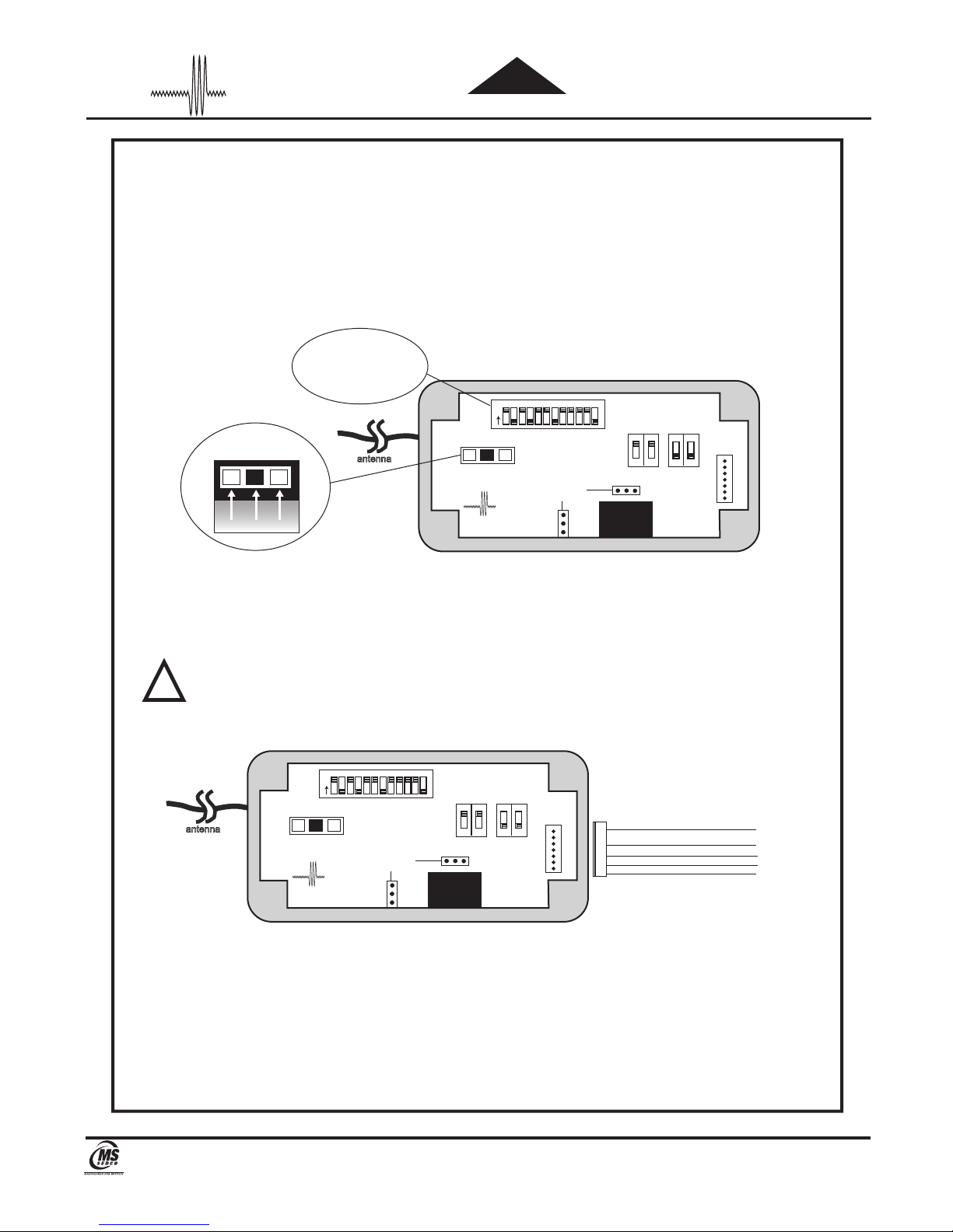
MODE #1—Standard Receiver
(Factory Setting-Activate Door Operators)
1. SELECT FREQUENCY: Remove CP/RX cover and select the desired frequency to match the transmitters via the
3-position slide switch on the receiver circuit board (Fig. 1).
2. SELECT SECURITY CODE: Select the desired security code to match the transmitters via the 12 dip switches on
the CP/RX circuit board (Fig. 1).
3. SELECT OPERATING MODE: Factory setting is Mode #1- DO NOTHING.
Figure 1
12 POSITION SECURITY
CODE SWITCH
HDRC™ Program 1-12
300 MHz Program 1-10
FREQUENCY SELECTION
SWITCH
HDRC™
300MHz 390MHz
390 MHz Program 1-12
antenna
ClearPath
1 2 3 4 5 6 7 8 9 10 11 12
O
N
™
CP/RX
ADD ON MODULE
PLUGS
TIME DELAY
SELECTION
SWITCH
RELAY 1
A B
onon
OPERATING
SELECTION
C D
MODE
SWITCH
onon
WIRE
HARNESS
PLUG
4. Mount the CP/RX in its intended location and plug in the provided wiring harness.
5. Connect device to be controlled to appropriate wires (Fig. 2).
6. Connect power to the appropriate wires (Fig. 2).
7. Install CP/RX cover with 4 screws provided.
ATTENTION: If CP/RX is installed inside a door operator housing, drill a small hole in the housing and
pull the receiver antenna wire through it to ensure radio reception is not inhibited.
!
Figure 2
1 2 3 4 5 6 7 8 9 10 11 12
O
antenna
N
FREQUENCY SELECTION
SWITCH
HDRC™
300MHz 390MHz
ADD ON MODULE
ClearPath
™
PLUGS
CP/RX
Input Voltage: 12 - 24V AC or DC
*Surge suppression circuitry is built in. Therefore it can directly
drive Mag Locks or Electric Strikes without additional protection.
TIME DELAY
SELECTION
SWITCH
onon
A B
RELAY 1
RED + (POS)
BLACK - (NEG)
onon
C D
OPERATING
MODE
SELECTION
SWITCH
WIRE
HARNESS
PLUG
RED
1
BLK
3
WHT
5
BROWN
6
VIO
7
N.C.
COM
N.O.
+
-
12-40V AC OR DC
Telephone: (317) 842-2545 www.mssedco.com custsvc@mssedco.com
8701 Castle Park Drive Indianapolis, Indiana 46256
Page 3
(82A022) CP/RXv0913
Page 4

CP/RX
Multi-Mode Radio Receiver and Timing Module INSTALLATION INSTRUCTIONS
hClearPat
™
HDRC
™
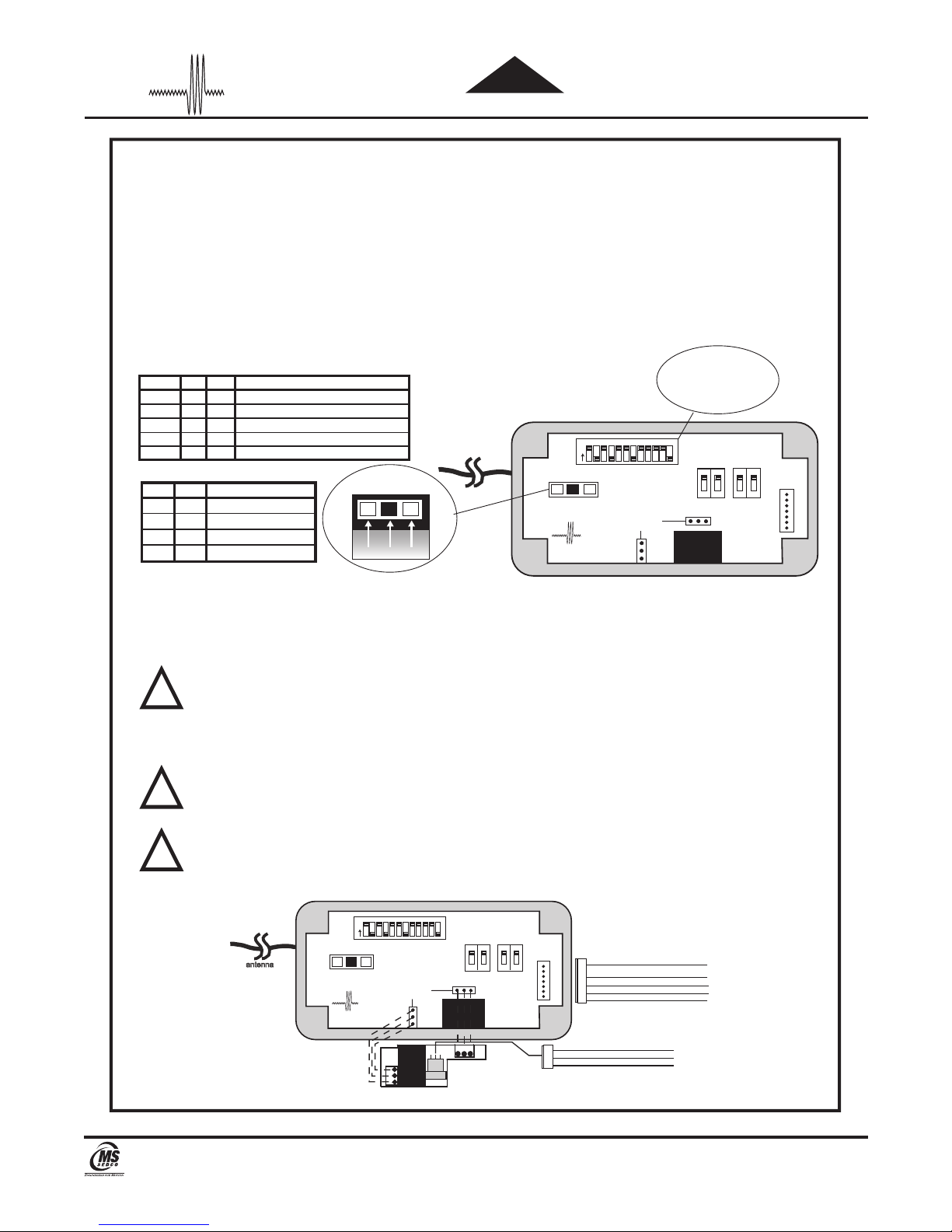
MODE #2—Receiver With Adjustable Time Delay Output
(Releases Electric Locking Devices)
1. SELECT FREQUENCY: Remove CP/RX cover and select the desired frequency to match the
transmitters via the 3-position slide switch on the receiver circuit board (Fig. 1).
2. SELECT SECURITY CODE: Select the desired security code to match the transmitters via the 12 dip
switches on the CP/RX circuit board (Fig. 1).
3. SELECT OPERATING MODE: Using the Table 1 select Mode #2 via the dip switches marked C & D
located on the CP/RX circuit board (Fig. 1).
4. SELECT TIME DELAY: Using Table 2 select the desired time delay via the dip switches marked A & B
on the CP/RX printed circuit board (Fig. 1).
Table 1 Table 2
Mode# C D Operating Mode
1 OFF OFF Normal Receiver (Factory Setting)
2 ON OFF Receiver with Time Delayed Output
12 POSITION SECURITY
FREQUENCY SELECTION
SWITCH
HDRC™
300MHz 390MHz
CODE SWITCH
HDRC™ Program 1-12
300 MHz Program 1-10
390 MHz Program 1-12
antenna
Figure 1
ClearPath
CP/RX
1 2 3 4 5 6 7 8 9 10 11 12
O
N
ADD ON MODULE
™
PLUGS
A B Time Delay
ON ON 5 Seconds
ON OFF 10 Seconds
OFF ON 15 Seconds
OFF OFF 20 Seconds
TIME DELAY
SELECTION
SWITCH
A B
RELAY 1
onon
OPERATING
SELECTION
SWITCH
C D
MODE
onon
WIRE
HARNESS
PLUG
5. Mount the CP/RX in its intended location and plug in the provided wiring harness.
6. Connect device to be controlled to appropriate wires (Fig. 2).
7. Connect power to the appropriate wires (Fig. 2).
8. Activate the CP/RX to verify the system is working properly. If further time delay adjustment is
required to the unit, refer back to step 4.
ATTENTION: Changing the operating mode or time delay settings after power is applied requires a 6
second delay for the new programming to take effect.
!
9. Install CP/RX cover with 4 screws provided.
ATTENTION: If CP/RX is installed inside a door operator housing, drill a small hole in
the housing and pull the receiver antenna wire through it to ensure radio reception is not
!
inhibited.
Figure 2
1 2 3 4 5 6 7 8 9 10 11 12
O
N
FREQUENCY SELECTION
SWITCH
antenna
HDRC™
300MHz 390MHz
ClearPath
ADD ON MODULE
™
PLUGS
CP/RX
*Surge suppression circuitry is built in. Therefore it can directly drive Mag Locks or Electric Strikes without additional protection.
Input Voltage: 12 - 24V AC or DC, RED + (POS), BLACK - (NEG)
TIME DELAY
SELECTION
SWITCH
RELAY 1
A B
onon
OPERATING
SELECTION
C D
MODE
SWITCH
onon
WIRE
HARNESS
PLUG
RED
1
BLK
3
WHT
5
BROWN
6
VIO
7
N.C.
COM
N.O.
+
-
12-40V AC OR DC
Telephone: (317) 842-2545 www.mssedco.com custsvc@mssedco.com
8701 Castle Park Drive Indianapolis, Indiana 46256
Page 4
(82A022) CP/RXv0913
Page 5

CP/RX
Multi-Mode Radio Receiver and Timing Module INSTALLATION INSTRUCTIONS
hClearPat
™
HDRC
™
MODE #3—Dual Receiver
(Day/Night Function)
NOTE: This Mode requires BOTH the CP/RX and the RXM ADD ON MODULE
1. SELECT FREQUENCY: Remove CP/RX cover and select the desired frequency to match the transmitters via the
3-position slide switch on the receiver circuit board (Fig. 1).
2. SELECT SECURITY CODE: Select the desired security code to match the transmitters via the 12 dip switches on
the CP/RX circuit board (Fig. 1).
3. SELECT OPERATING MODE: Using table below select mode #3 via the dip switches marked C & D located on
the CP/RX printed circuit board.
ClearPath
CP/RX
Figure 1
1 2 3 4 5 6 7 8 9 10 11 12
O
N
™
ADD ON MODULE
PLUGS
Table 1
Mode# C D Operating Mode
1 OFF OFF Normal Receiver (Factory Setting)
2 ON OFF Receiver with Time Delayed Output
3 OFF ON Dual Receiver
4 ON ON Receiver With Sequenced Outputs
5 N/A N/A Receiver With Ratchet Relay
FREQUENCY SELECTION
SWITCH
HDRC™
300MHz 390MHz
antenna
4. Set one transmitter to match the security code of the CP/RX selected in step 2. Set a second transmitter to
this same code EXCEPT dip switch #2 which should be opposite to dip switch #2 on the CP/RX (Fig. 2).
Figure 2
If the and one
Receiver
Transmitter
the same, like this,
code are set
(Activates CP/RX)
3 5 64 7
1 2
0
N
8 91011
then
12
Note #2 switch
in opposite position!
The second
should be set like this.
(Activates RXM)
3 5 64 7
1 2
0
N
12 POSITION SECURITY
HDRC™ Program 1-12
300 MHz Program 1-10
390 MHz Program 1-12
RELAY 1
Transmitter
8 91011
12
CODE SWITCH
TIME DELAY
SELECTION
SWITCH
onon
A B
OPERATING
SELECTION
C D
MODE
SWITCH
onon
WIRE
HARNESS
PLUG
5. Plug the 3-lead wire harness supplied with the RXM (purchased separately) into its connector on the RXM
circuit board and then plug the entire assembly onto the CP/RX circuit board (Fig. 3).
6. Mount the CP/RX in its intended location and plug the 5-lead wiring harness provided into its connector on the
CP/RX circuit board (Fig. 3).
7. Connect each device to be controlled to the appropriate wires (Fig. 3).
8. Connect power to the appropriate wires (Fig. 3).
ATTENTION: Changing the operating mode or time delay settings after power is applied requires a 6
second delay for the new programming to take effect.
!
9. Install CP/RX cover with 4 screws provided.
ATTENTION: If CP/RX is installed inside a door operator housing, drill a small hole in the housing and
pull the receiver antenna wire through it to ensure radio reception is not inhibited.
!
Figure 3
1 2 3 4 5 6 7 8 9 10 11 12
O
antenna
N
FREQUENCY SELECTION
SWITCH
HDRC™
300MHz 390MHz
ClearPath
ADD ON MODULE
™
CP/RX
PLUGS
RXM
TIME DELAY
SELECTION
SWITCH
onon
A B
RELAY 1
RELAY 2
Plug the wire harness into its connector BEFORE attaching the module
to the CP/RX circuit board.
onon
C D
OPERATING
MODE
SELECTION
SWITCH
WIRE
HARNESS
PLUG
3
2
1
BROWN
VIO
WHITE
RED
1
BLK
3
WHT
5
BROWN
6
VIO
7
N.O.
N.C.
N.C.
COM
N.O.
+
-
12-40V AC OR DC
COM
Telephone: (317) 842-2545 www.mssedco.com custsvc@mssedco.com
8701 Castle Park Drive Indianapolis, Indiana 46256
Page 5
(82A022) CP/RXv0913
Page 6
CP/RX
Multi-Mode Radio Receiver and Timing Module INSTALLATION INSTRUCTIONS
hClearPat
™
HDRC
™
MODE #4—Receiver With Two Sequenced Outputs
(Sequences Electric Locks & Door Operators)
NOTE: This Mode requires BOTH the CP/RX and the RXM ADD ON MODULE
1. SELECT FREQUENCY: Remove CP/RX cover and select the desired frequency to match the transmitters via the
3-position slide switch on the receiver circuit board (Fig. 1).
2. SELECT SECURITY CODE: Select the desired security code to match the transmitters via the 12 dip switches on
the CP/RX circuit board (Fig. 1).
3. SELECT OPERATING MODE: Using Table 1 select Mode #4 via the 2 dip switches marked C & D located on the
CP/RX printed circuit board.
4. SELECT TIME DELAY: Using Table 2 select the desired output time delays via the dip switches marked A & B on
the CP/RX circuit board.
12 POSITION SECURITY
Mode# C D Operating Mode
Table 1
1 OFF OFF Normal Receiver (Factory Setting)
2 ON OFF Receiver with Time Delayed Output
3 OFF ON Dual Receiver
4 ON ON Receiver With Sequenced Outputs
5 N/A N/A Receiver With Ratchet Relay
Table 2
A B Time Delay
FREQUENCY SELECTION
SWITCH
antenna
Figure 1
1 2 3 4 5 6 7 8 9 10 11 12
O
N
ON ON 5 Seconds
ON OFF 10 Seconds
OFF ON 15 Seconds
OFF OFF 20 Seconds
HDRC™
300MHz 390MHz
ClearPath
CP/RX
™
ADD ON MODULE
PLUGS
5. Plug the 3-lead wire harness supplied with the RXM (purchased separately) into its connector on the RXM
circuit board and then plug the entire assembly onto the CP/RX circuit board (Fig. 2).
6. Mount the CP/RX in its intended location and plug the 5-lead wiring harness provided into its connector on the
CP/RX circuit board (Fig. 2).
7. Connect each device to be controlled to the appropriate wires (Fig. 2).
NOTE: Relay #1 on the CP/RX circuit board activates first. Relay #2 on the RXM add on module
activates second.
!
8. Connect power to the appropriate wires (Fig. 2).
9. Activate the CP/RX to verify the system is working properly. If further time delay adjustment is required
to the unit, refer back to step 4.
ATTENTION: Changing the operating mode or time delay settings after power is applied requires a 6
second delay for the new programming to take effect.
!
10. Install CP/RX cover with 4 screws provided.
ATTENTION: If CP/RX is installed inside a door operator housing, drill a small hole in the housing and
pull the receiver antenna wire through it to ensure radio reception is not inhibited.
!
CODE SWITCH
HDRC™ Program 1-12
300 MHz Program 1-10
390 MHz Program 1-12
TIME DELAY
SELECTION
SWITCH
onon
A B
C D
OPERATING
MODE
SELECTION
SWITCH
RELAY 1
onon
WIRE
HARNESS
PLUG
FREQUENCY SELECTION
antenna
300MHz 390MHz
ClearPath
Telephone: (317) 842-2545 www.mssedco.com custsvc@mssedco.com
Figure 2
1 2 3 4 5 6 7 8 9 10 11 12
O
N
SWITCH
HDRC™
ADD ON MODULE
PLUGS
™
CP/RX
RXM
8701 Castle Park Drive Indianapolis, Indiana 46256
TIME DELAY
SELECTION
SWITCH
onon
A B
RELAY 1
RELAY 2
Plug the wire harness into its connector BEFORE attaching the module
to the CP/RX circuit board.
onon
C D
OPERATING
MODE
SELECTION
SWITCH
WIRE
HARNESS
PLUG
3
2
1
BROWN
VIO
WHITE
RED
1
3
BLK
WHT
5
BROWN
6
7
VIO
N.O.
N.C.
N.C.
COM
N.O.
+
-
12-40V AC OR DC
COM
Page 6
(82A022) CP/RXv0913
Page 7

CP/RX
Multi-Mode Radio Receiver and Timing Module INSTALLATION INSTRUCTIONS
hClearPat
™
HDRC
™
MODE #5—Receiver With Ratchet Relay
(Initial Signal Holds Relay Closed Until A Second Signal Is Received)
NOTE: This Mode requires BOTH the CP/RX and the RXR ADD ON MODULE
1. SELECT FREQUENCY: Remove CP/RX cover and select the desired frequency to match the transmitters via the
3-position slide switch on the receiver circuit board (Fig. 1).
2. SELECT SECURITY CODE: Select the desired security code to match the transmitters via the 12 dip switches on
the CP/RX circuit board (Fig. 1).
3. SELECT OPERATING MODE: Plug the RXR (purchased separately) onto the main PCB (Fig. 2). The relay will
automatically convert to the ratchet mode–no operating mode switch is necessary (Table 1).
4. Mount the CP/RX in its intended location and plug the 5-lead wiring harness provided into its connector on the
CP/RX circuit board (Fig. 2).
12 POSITION SECURITY
Mode# C D Operating Mode
Table 1
1 OFF OFF Normal Receiver (Factory Setting)
2 ON OFF Receiver with Time Delayed Output
3 OFF ON Dual Receiver
4 ON ON Receiver With Sequenced Outputs
5 N/A N/A Receiver With Ratchet Relay
FREQUENCY SELECTION
SWITCH
HDRC™
300MHz 390MHz
antenna
ClearPath
CP/RX
Figure 1
1 2 3 4 5 6 7 8 9 10 11 12
O
N
™
ADD ON MODULE
PLUGS
CODE SWITCH
HDRC™ Program 1-12
300 MHz Program 1-10
390 MHz Program 1-12
TIME DELAY
SELECTION
SWITCH
onon
A B
C D
OPERATING
MODE
SELECTION
SWITCH
RELAY 1
onon
WIRE
HARNESS
PLUG
5. Connect device to be controlled to the appropriate wires (Fig. 2).
6. Connect power to the appropriate wires (Fig. 2).
7. Activate the CP/RX to verify the system is working properly.
ATTENTION: Changing the operating mode or time delay settings after power is applied requires a 6
second delay for the new programming to take effect.
!
8. Install CP/RX cover with 4 screws provided.
ATTENTION: If CP/RX is installed inside a door operator housing, drill a small hole in the housing and
pull the receiver antenna wire through it to ensure radio reception is not inhibited.
!
Figure 2
1 2 3 4 5 6 7 8 9 10 11 12
O
antenna
N
FREQUENCY SELECTION
SWITCH
HDRC™
300MHz 390MHz
ClearPath
ADD ON MODULE
™
CP/RX
PLUGS
TIME DELAY
SELECTION
SWITCH
RELAY 1
A B
onon
onon
C D
OPERATING
MODE
SELECTION
SWITCH
WIRE
HARNESS
PLUG
RXR
RED
1
3
BLK
WHT
5
BROWN
6
7
VIO
12-40V AC OR DC
N.C.
COM
N.O.
+
-
Telephone: (317) 842-2545 www.mssedco.com custsvc@mssedco.com
8701 Castle Park Drive Indianapolis, Indiana 46256
Page 7
(82A022) CP/RXv0913
 Loading...