

Page 1
614 Series
Extreme Door Activator Switches INSTALLATION INSTRUCTIONS
Section 1
General Description
The 614 series extreme door activator switches are
designed to provide reliable activation of any automatic
door in extreme environments. This 1" diameter button
switch is completely waterproof and virtually
indestructible. The face plates come in two sizes.
614-SS: 4 1/2" square face plate (fits single-gang
electrical box)
614-NSS: 1 11/16" x 4 1/2" face plate (fits 1 3/4"
door frame)
Section 2
Basic Installation
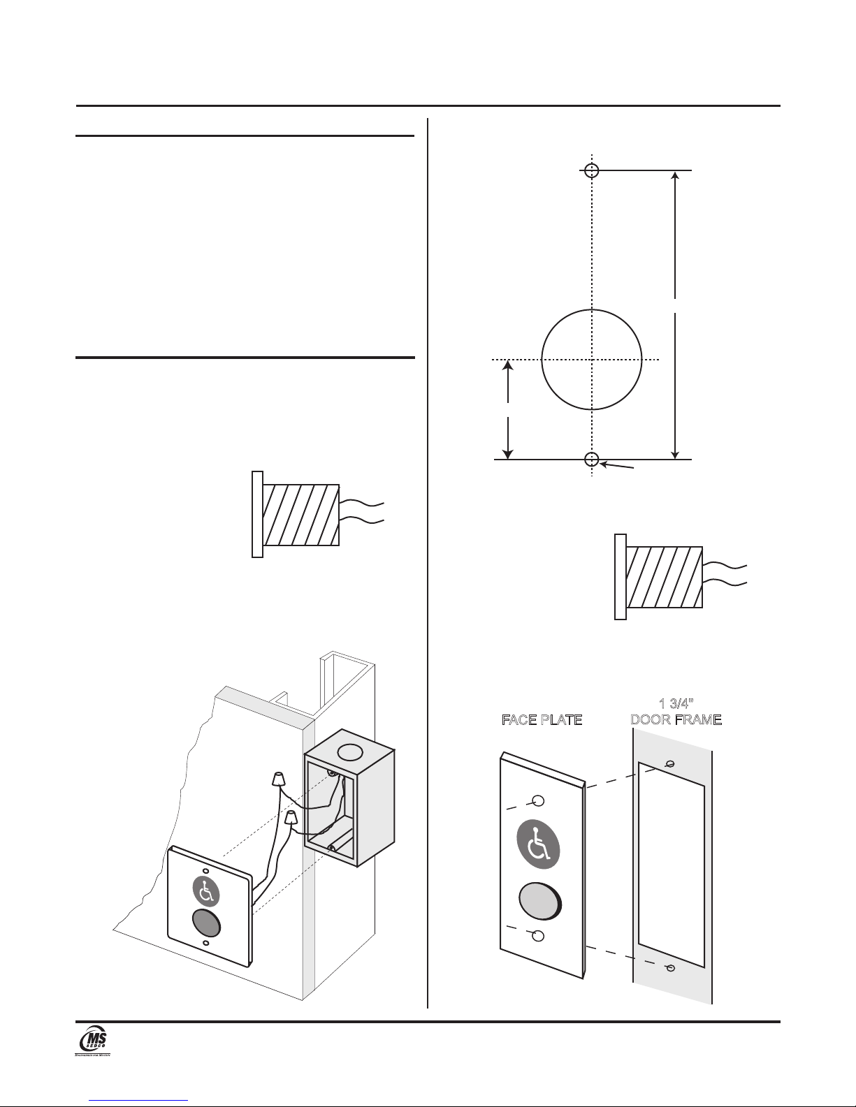
614-SS: 4 1/2" Square Face Plate
1) Mount a standard single-gang electrical box in its
intended location.
2) Connect the necessary signal wires to the switch
wires.
1" Diameter
Red Anodized Aluminum
Piezo Technology
3) Attach the switch assembly to the electrical box with
the 6-32 x 1" screws provided.
MAX TORQUE 4 inch.-lbs. DO NOT OVER TIGHTEN!
COM
N.O.
614-NSS: 1 11/16" x 4 1/2" Face Plate
1) Make the required cutout in the door frame.
3 1/4"
1 1/8"
DRILL & TAP 6-32
C/ L
2) Connect the necessary signal wires to the switch
wires.
1" Diameter
Red Anodized Aluminum
Piezo Technology
(2 Places)
COM
N.O.
3) Attach the switch assembly in the cutout prepared in
step 1 with the 6-32 x 1" screws provided.
MAX TORQUE 4 inch.-lbs. DO NOT OVER TIGHTEN!
FACE PLAT E
7898 Zionsville Road Indianapolis, Indiana 46268
Telephone: (317) 842-2545 www.mssedco.com custsvc@mssedco.com
1 3/4"
DOOR FRAME
Page 1
(/MANU) 614v1217
Page 2
614 Series
Extreme Door Activator Switches INSTALLATION INSTRUCTIONS
NOTICE: For surface mounting applications,
order the 1015 surface mount box for the 614;
!
the 1106-A surface mount box for the 614-N.
NOTICE: For radio control applications, order
the CP/TX transmitter with surface mount
!
box for the 614; the CP/TX-J transmitter with
surface mount box for the 614-N.
For further technical assistance, contact the factory at
1-317-842-2545.
Section 3
Basic Installation
Rated Voltage.......................... 0 to 24V AC or DC;60V Max.
Current....................................................................... 0.100A
Switch Resistance "ON"..................................... <100 Ohms
Switch Resistance "OFF".................................. >5 Megohms
Actuation Force......................................................... 3 to 5 N
Operating Temperature.. -40°F (-20°C) to 257°F (125°C)
Cycles................................................................... >50 Million
Telephone: (317) 842-2545 www.mssedco.com custsvc@mssedco.com
7898 Zionsville Road Indianapolis, Indiana 46268
Page 2
(/MANU) 614v1217
 Loading...