

Page 1
216, 216-L, 216-N
Active Infrared "Touchless" Switch INSTALLATION INSTRUCTIONS
Section 1
General Description
The 216 Series "touchless" switches are active infrared
devices designed for hands-free activation of automatic
door operators or other access control products. The 216
switch assembly will fit in a variety of locations from a
1 3/4" door frame to a single or 2-gang or junction
electrical box. Various size surface mounting boxes are
also available from the factory. Three standard face plate
sizes are available:
216: 4 1/2" x 4 1/2" stainless steel (fits single, 2 gang, junction electrical boxes)
216-L: 2 3/4" x 4 1/2" stainless steel (fits single gang
electrical boxes)
216-N: 1 11/16" x 4 1/2" stainless steel (fits 1 3/4"
door frames)
Section 2
Basic Installation
SINGLE GANG ELECTRICAL BOX: 216 & 216-L
1) Install the electrical box (purchased separately) in its
intended location.
2) Set the unit for its intended operating mode via the
jumpers on the side of the switch assembly: Fail
Close (factory setting), Fail Open or Toggle (Figure 1).
3) Make the appropriate electrical connections to the
switch assembly--4 wires are required (Figure 2).
4) Attach the switch assembly to the electrical box with
the two (2) 6-32 x 1/2" screws provided.
5) Adjust for range and time delay via the potentiometers
on the front of the switch assembly (Figure 3).
6) Attach face plate with the 6-32 x 3/8" screws provided
ensuring that the backside of the face plate lens and
the foam gasket on the front of the switch assembly
are less than 1/4" apart (Figure 4).
2-GANG ELECTRICAL BOX OR JUNCTION BOX: 216
1) Install the electrical box (purchased separately) in its
intended location.
2) Attach the adaptor ring provided (see below) to the
electrical box.
3) Set the unit for its intended operating mode via the
jumpers on the side of the switch assembly: Fail
Close (factory setting), Fail Open or Toggle (Figure 1).
4) Make the appropriate electrical connections to the
switch assembly--4 wires are required (Figure 2).
5) Attach the switch assembly to the adaptor ring
(mounted to the electrical box in step 2) with the 6-32
x 1/2" screws provided.
6) Adjust for range and time delay via the potentiometers
on the front of the switch assembly (Figure 3).
7) Attach face plate with the 6-32 x 3/8" screws provided
ensuring that the backside of the face plate lens and
the foam gasket on the front of the switch assembly
are less than 1/4" apart (Figure 4).
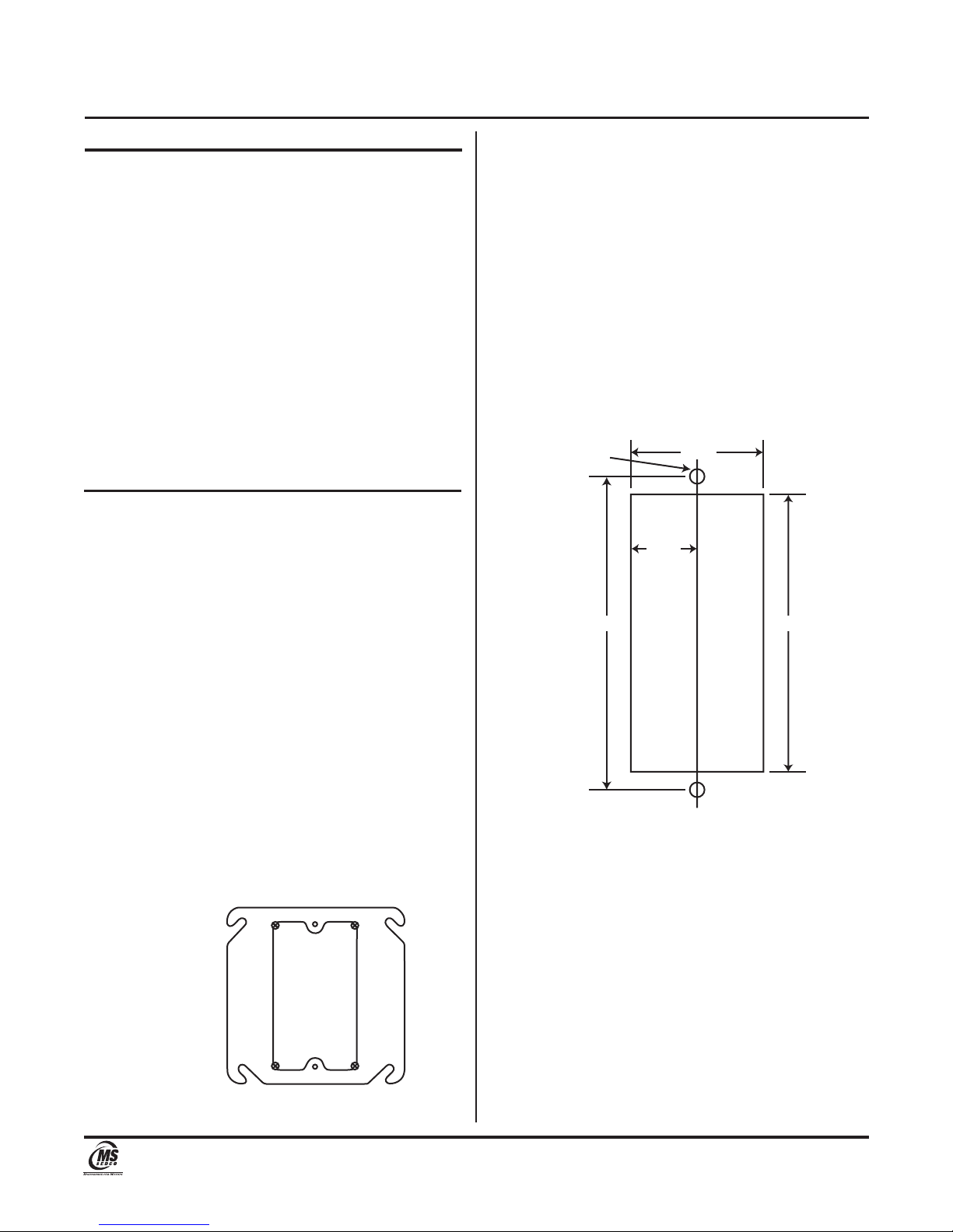
DOOR FRAME: 216-N
1) Make a cutout in the door frame at the intended
location. Drill and tap 2 mounting holes (see below).
DRILL & TAP
6-32 (2 Holes)
2) Set the unit for its intended operating mode via the
jumpers on the side of the switch assembly: Fail
Close (factory setting), Fail Open or Toggle (Figure 1).
3) Make the appropriate electrical connections to the
switch assembly--4 wires are required (Figure 2).
4) Mount the switch assembly in the cutout and attach
with the 6-32 x 1/2" screws provided.
5) Adjust for range and time delay via the potentiometers
on the front of the switch assembly (Figure 3).
6) Attach face plate with the 6-32 x 3/8" screws provided
ensuring that the backside of the face plate lens and
the foam gasket on the front of the switch assembly
are less than 1/4" apart (Figure 4).
3 1/4"
1 3/8"
11/16"
2 7/8"
Telephone: (317) 842-2545 www.mssedco.com custsvc@mssedco.com
8701 Castle Park Drive Indianapolis, Indiana 46256
Page 1
(82A023) 216v1014
Page 2

216, 216-L, 216-N
Active Infrared "Touchless" Switch INSTALLATION INSTRUCTIONS
Section 3
Technical Data
Model....................................... 216, 216-L, 216-N
Input Power.............................. 12-24V AC or DC
Input Current............................ Approx. 100 MA @ 18V AC
Output Connections................. 8" 22 AWG Leads
Output Rating........................... Form C, Rated at 3 Amps
Detection Scheme................... Coded Modulated Carrier
Codes Available....................... Automatic Self Changing ID
Coding
Activation Time........................ <0.03 seconds
Reaction Time.......................... 0.05 - 1 second
Operating Distance.................. 6" to 30"
Temperature Rating................ -13°F to 140°F
(-25°C to 60°C)
Weight...................................... <0.25 lbs.
Physical Size............................ 1 5/16"L x 4"W x 1 1/4"H
Section 4
Warranty
MS SEDCO guarantees this product to be free from manufacturing
defects for 1 year from date of installation. Unless MS SEDCO is
notified of the date of installation, the warranty will be in effect for
1 year from the date of shipment from our factory. If, during the
first year, our motion detector or support device fails to operate
and has not been tampered with our abused, the unit can be
returned prepaid to factory and it will be repaired free of charge.
After 1 year, the unit will be repaired for a nominal service charge.
This limited warranty is in lieu of all other warranties expressed
or implied, including any implied warranty of merchantability,
and no representative or person is authorized to assume for MS
SEDCO any other liability in connection with the sale of our
products. All warranties are limited to the duration of this
written warranty. In no event shall MS SEDCO be liable for any
special, incidental, consequential or other damages arising
from any claimed breach of warranty as to its products or
services.
Questions? Call us at 1-317-842-2545 or
visit us online at www.mssedco.com.
Telephone: (317) 842-2545 www.mssedco.com custsvc@mssedco.com
8701 Castle Park Drive Indianapolis, Indiana 46256
Page 2
(82A023) 216v1014
Page 3

216, 216-L, 216-N
Active Infrared "Touchless" Switch INSTALLATION INSTRUCTIONS
FIGURE 1—Operating Modes Diagram
WIRING
INPUT OUTPUT
2 RED GRN = COM
12-24V AC/DC BLU = N.O.
NO POLARITY VIO = N.C.
JP1
JP2
JP1
JP2
JP1 JP2
CUT FAIL OPEN TOGGLE
MODE MODE
IN FAIL CLOSE DELAY
MODE MODE
Jumper 1 = JP1
Jumper 2 = JP2
Cut here with knife
SIDE VIEW
1) Standard "Fail Close" Mode (Factory Setting): This is the most common operating mode. In this
mode, if power were to fail to the 216 series switch, the door it is activating will stay closed (the
switch relay is in its inactive state). The unit is shipped from the factory in this mode - no change
to the jumpers is necessary. Wire connections are COM and N.O.
2) Optional "Fail Open" Mode (Cut Jumper 1): In this mode, if power were to fail to the 216 series
switch, the door it is activating will open (the switch relay is in its active state). In order to program
this mode, cut Jumper 1. Wire connections are COM and N.C.
3) Toggle Mode: In this mode, when the 216 series switch is activated, the relay is energized and
maintains that state until it is activated again, returning the relay to its de-energized state. For
example, a 216 series switch could be located at the entrance of a room. When a person enters,
the 216 series switch turns on the light. As they exit, the 216 series switch turns off the light. In
order to program this mode, cut Jumper 2. Wire connections are COM and N.O.
!
Input Connections Output Connections
12-24V AC or DC Green = Common (COM)
Red and black wires have no polarity on this product. Blue = Normally Open (N.O.)
Do not tie either of the power supply lines to ground. Violet = Normally Closed (N.C.)
The power in must “float” and not be grounded.
Fail Close Mode (Factory Setting): Wire connections COM & N.O.
Fail Open Mode: Cut Jumper 1; wire connections COM & N.C.
Toggle Mode: Cut Jumper 2; wire connections COM & N.O.
Telephone: (317) 842-2545 www.mssedco.com custsvc@mssedco.com
FIGURE 2—Wiring Diagram
8701 Castle Park Drive Indianapolis, Indiana 46256
Page 3
(82A023) 216v1014
Page 4

216, 216-L, 216-N
Active Infrared "Touchless" Switch INSTALLATION INSTRUCTIONS
FIGURE 3—Adjustments Diagram
Range Adjustment: Clockwise to increase
6" to 30".
ACTIVATION
INDICATOR
LED
RANGE
6" to 30"
REACTION
TIME
0.05-1 Sec.
INC
INC
NOTE: When attaching the face plate, the
range may increase.
Reaction Time Adjustment: Clockwise to increase
0.05 to 1 second.
FRONT VIEW
FIGURE 4—Face Plate Installation Diagram
WARNING: For proper operation, the backside
of the face plate lens must be no more than
!
1/4" from the foam gasket on the switch
assembly (no more than 1/4" of space
between the lens and the foam gasket). For
optimum performance, the lens and foam
gasket should be touching
!
FACE PLATE
SWITCH
ASSEMBLY
WARNING: When attaching the face plate to
the switch assembly, only use 6-32 x 3/8"
!
screws provided. Use of longer screws may
cause damage to the unit.
Telephone: (317) 842-2545 www.mssedco.com custsvc@mssedco.com
LENS
8701 Castle Park Drive Indianapolis, Indiana 46256
FOAM
GASKET
MAX. 1/4"
GAP
SIDE VIEW
Page 4
(82A023) 216v1014
 Loading...