

Page 1

28
TRINITY 500
OWNER’S MANUAL
Page 2

2
CONTENTS
1. INTRODUCTION page 3
1.1 TRINITY HOUSE page 4
2. PRE-USE CHECK LIST page 6
3. THE CRAFT page 7
4. SAFETY page 9
5. HANDLING page 16
6. CARE AND MAINTENANCE page 18
7. EC CONFORMITY page 20
8. IDENTIFICATION page 23
9. WARRANTY page 23
10. GLOSSARY page 24
Page 3

3
1. INTRODUCTION
Congratulations on buying a Trinity 500 Class pulling boat. The boat
was designed by Jo Richards, Olympic medallist and designer of the
Pico series, in response to the requirement of the Sea Cadets for a
modern, low maintenance, purpose-designed fixed seat rowing boat
with good performance under oars and with the capacity to mount a
small outboard motor. The Sea Cadets are governed by the MSSC
(Marine Society & Sea Cadets).
This manual has been compiled to help you to operate your craft with
safety and pleasure. It contains details of the craft, the equipment
supplied or fitted and information on their operation. Please read it
carefully and familiarise yourself with the craft and its equipment before
using it.
PLEASE KEEP THIS MANUAL IN A SECURE PLACE AND HAND
IT OVER TO THE NEW OWNER WHEN YOU SELL THE CRAFT.
Terms in
blue in this manual can be found in the glossary, in Section 10.
This owner's manual is not a course on boating safety or seamanship.
If this is your first craft, or if you are changing to a type of craft you are
not familiar with, for your own comfort and safety, please ensure that
you obtain handling and operating experience before assuming
command of the craft. Your dealer, national sailing federation or
yacht club will be pleased to advise you of local sea schools or
competent instructors.
In some countries a driving licence or authorisation are required,
or specific regulations are in force.
The Trinity 500 is named to mark the quincentenary of the incorporation
of Trinity House, the statutory authority for aids to navigation in England,
Wales, the Channel Islands and Gibralter. The Trinity House Maritime
Charity, a separately funded arm of the Corporation of Trinity House,
generously funded the design and development costs of the boat.
Page 4

4
1.1 TRINITY HOUSE
The origins of Trinity House are obscure and it is often stated that
these date back to a charitable guild established by Archbishop
Stephen Langton in the 13th Century. However, Henry VIII gave Trinity
House a charter in 1514 for the regulation of shipping.
It is widely known that Trinity House provides lighthouses for this is its
statutory duty as the General Lighthouse Authority for England, Wales,
the Channel Islands and Gibraltar, functions set out in Part VIII of the
UK Merchant Shipping Act, 1995. As such Trinity House is responsible
for the provision of aids to navigation to assist the safe passage of
vessels in general navigation. These comprise nearly 600 stations
ranging from traditional aids such as lighthouses, buoys and beacons,
to a satellite-based differential global positioning service (GPS). Trinity
House is also responsible for the inspection and auditing of over
10,000 local aids to navigation provided by port and harbour
authorities and those provided on offshore structures, such as
production platforms or wind farms. It also has a responsibility for
locating and marking wrecks that are a danger to general navigation
and arranging for their dispersal to a safe depth.
Funding for these activities is raised from light dues levied on vessels
calling at ports in the United Kingdom and Ireland and based on net
registered tonnage or registered length in the case of tugs and fishing
vessels. These dues are paid into the General Lighthouse Fund,
managed by the Department for Transport.
Trinity House is also a Deep Sea Pilotage Authority and currently
licenses 40 deep sea pilots for North West European waters. There is
a need by owners and operators of high risk vessels to have a highly
experienced master mariner with expert knowledge of our congested
waters join the bridge team for the European turnaround.
As the UK’s largest fully endowed maritime charity the Corporation of
Trinity House operates as a separate entity to the Lighthouse Service.
It is funded principally by its endowments and spends over £3 million
each year on the welfare of mariners, the education and training of
future seafarers as well as the promotion of safety at sea. The
Corporation runs an estate of almshouses at Walmer, in Kent, for
Page 5

5
retired mariners and their widows; manages the Trinity House
Merchant Navy Scholarship Scheme, selecting and sponsoring
Merchant Navy Cadets through nautical college. It supports a range of
maritime activities and other charities, including the MSSC, and funds
research into issues that will improve maritime safety. These charitable
activities complement the navigation responsibilities of Trinity House
enabling it to discharge its corporate social responsibility to the
maritime community.
The long association between Trinity House and the MSSC has been
further consolidated with the support for this pulling boat bearing the
name TRINITY 500.
Trinity House – Supporting the Mariner Past,
Present and Future.
Page 6

6
2. PRE-USE CHECK LIST
1. Buoyancy chamber is free of water.
2. Buoyancy chamber access hatches at bow and stern are properly
closed.
3. Buoyancy chamber bung at stern is tightly closed.
4. No splits in hull, no scratches penetrating into foam layer of hull.
5. Equipment:
• 5 Rowlocks, secured by lanyards
• Righting lines rigged both sides and not weakened by chafe
• Rudder in place and secured by spring clip (unless using outboard)
• Bailer, secured by lanyard
• Warps for securing boat alongside or to mooring
• 5 oars, no splits or cracks in shafts or blades, spare oar secured in
boat
• Boathook, secured in boat
• Means of communication with shore
• Fenders (optional)
• Anchor and warp (optional)
• Outboard (if used) properly secured, rudder unshipped
• Fire extinguisher carried and secured in boat, if outboard motor to
be used.
6. Crew correctly dressed for conditions.
7. Crew wearing buoyancy aids/personal flotation aids correctly.
8. Crew briefed on safety precautions as laid down in this manual,
coxswain’s words of command and how to right boat in case
of capsize.
Page 7
7
3. THE CRAFT
Dimensions
Length overall 5.5 m
Beam 1.76 m
Draft 0.45 m
Air draft 1 m
Mass of hull 225 kg
Mass of fully loaded boat 1017 kg
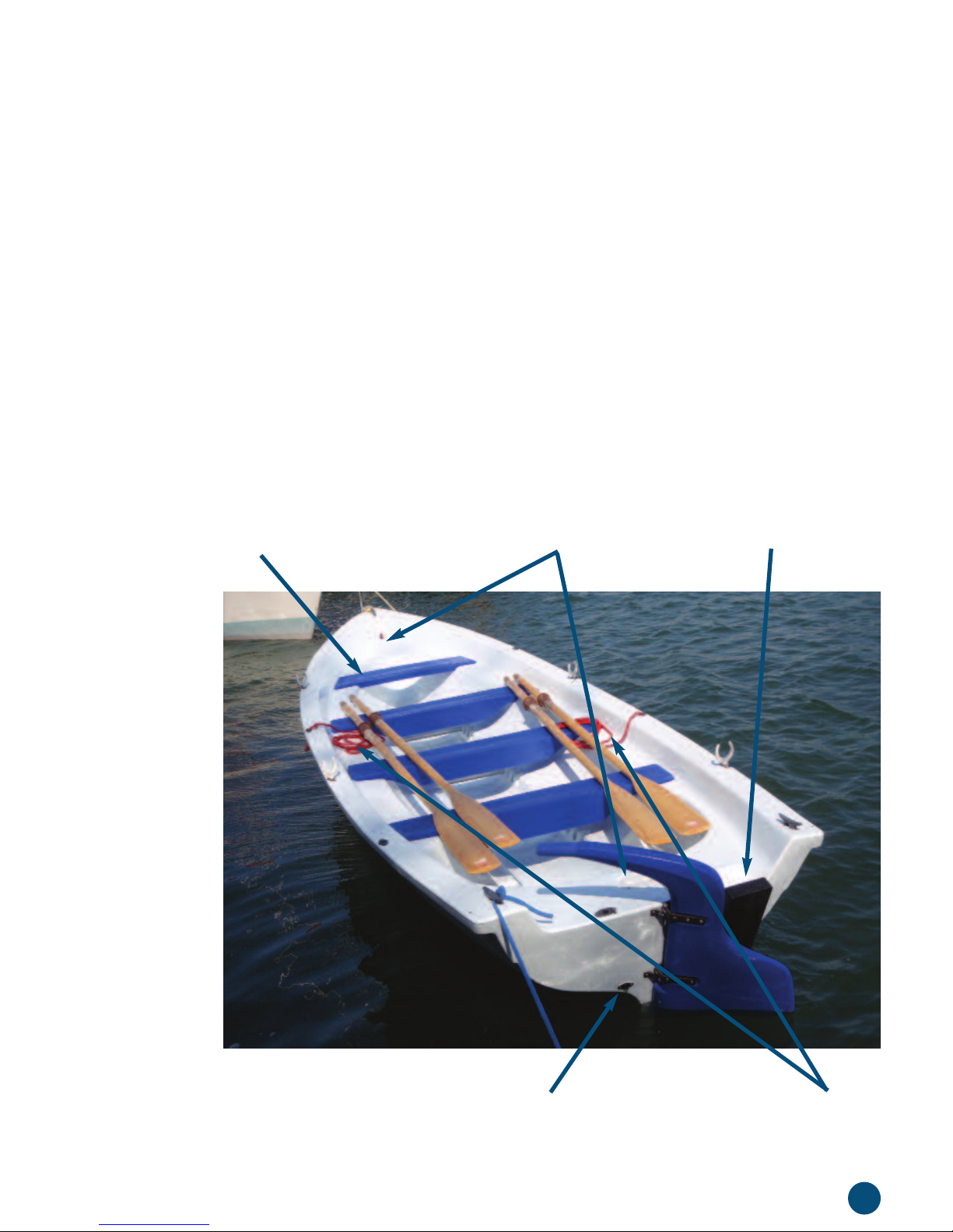
General layout
Buoyancy chamber bung
Outward motor bracket
Righting lines
Buoyancy chamber hatchesThwart
Page 8

8
Rudder and tiller
The rudder and tiller are combined in a single moulding. It fits on
gudgeons and pintles on the transom. When fitted, it is held in place
by a spring clip on the upper pintle.
Page 9

9
4. SAFETY
The craft should have onboard the appropriate safety equipment
(lifejackets etc.) according to the type of craft, weather conditions, etc.
This equipment is mandatory in some countries. The crew should be
familiar with the use of all safety equipment and emergency
manoeuvring (man overboard recovery, towing, etc.). Sailing schools
and clubs regularly organise drill sessions if you neef more training.
Everyone should wear a suitable buoyancy aid (life jacket/personal
floatation device) when onboard. In some countries it is a legal
requirement to wear a buoyancy aid that complies with national
regulations at all times.
4.1 OWNER’S RESPONSIBILITY
The responsibility for safe operation of any boat rests with the owner.
It is the owner’s responsibility to ensure that the boat is safe to use
and that the coxswain and crew are capable of operating the boat so
they are not a hazard to themselves or other water users.
4.2 DESIGN CATEGORY
Ensure that the you and your crew are able to handle the craft in the
anticipated wind and sea conditions and that these correspond to the
design category of your craft.
Design Category D: The Trinity 500 is designed for use in waters of
Design Category D, Sheltered Waters; on small lakes, rivers and
canals where conditions up to wind force 4 and significant wave
heights up to 0.5 m may be experienced.
Always adjust the speed and direction of the craft to the sea
conditions.
Page 10
10
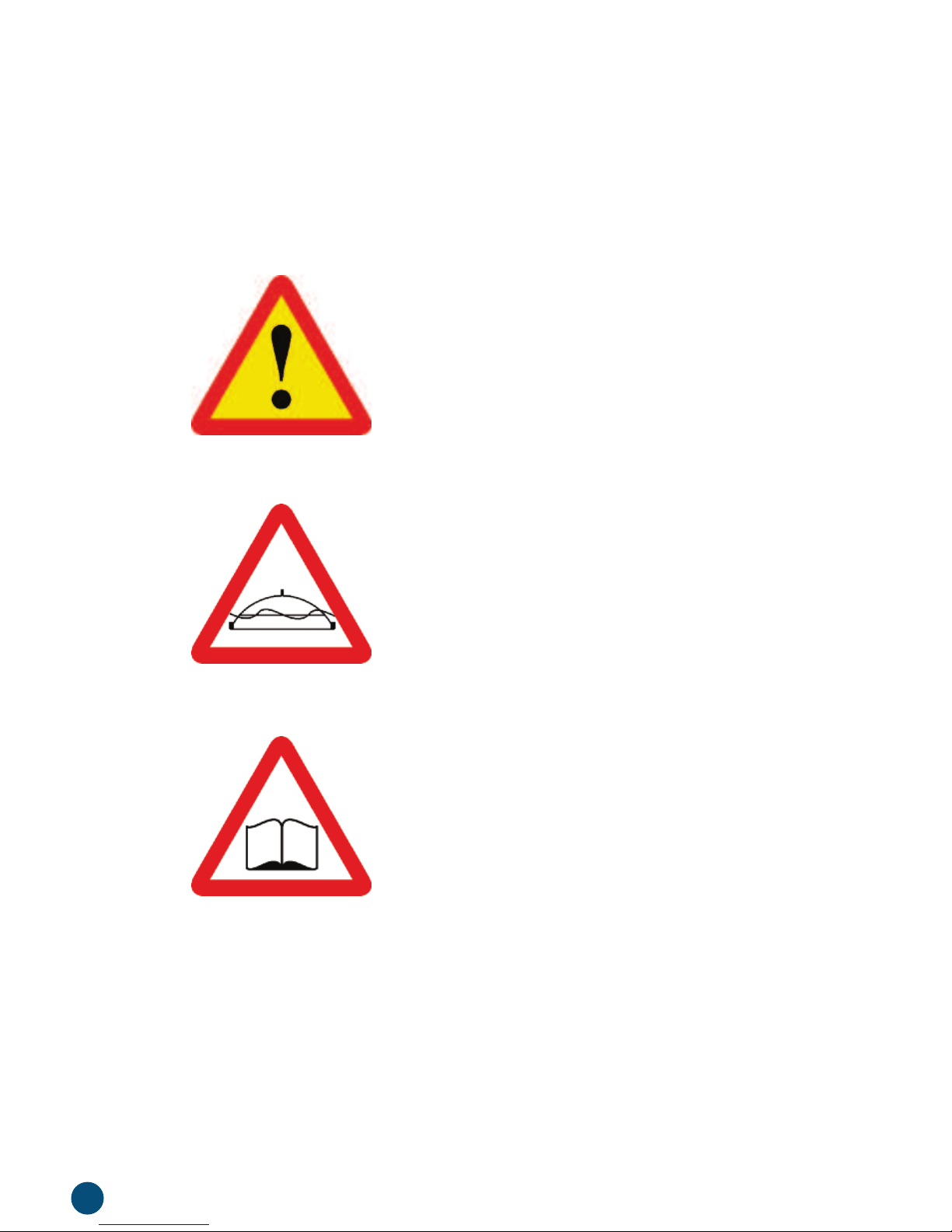
4.3 SAFETY LABELS
The following safety labels appear on the Trinity 500 Builders Plate.
The meaning of each is:
Warning: Injury or death may occur if
proper precautions are not taken.
Risk of capsize: The boat may capsize
in certain circumstances.
Read owner’s manual: The boat’s
users should read this manual before
going afloat.
Page 11
11
4.4 LOADING CAPACITY
Maximum and minimum weight
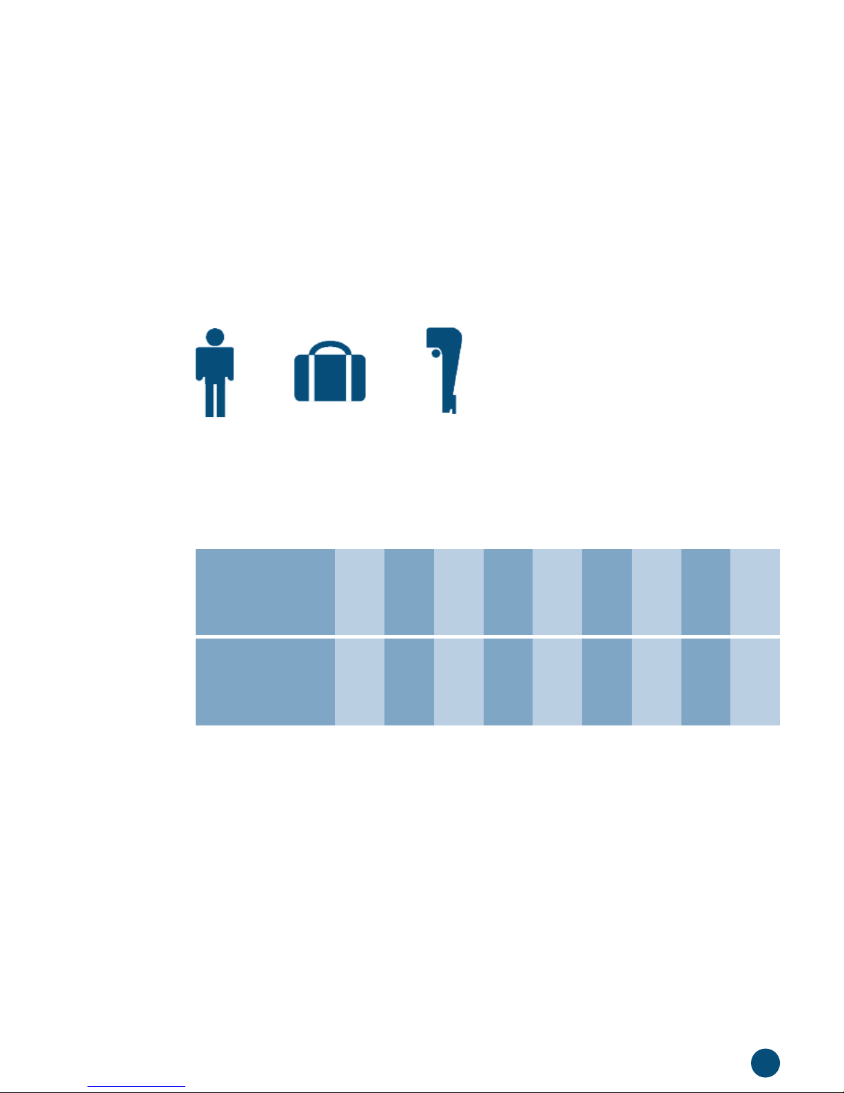
The Builder’s Plate shows the following safe loading information,
which means:
Number
of people:
Maximum
weight of
equipment (kg):
10 98765432
42 117 192 267 342 417 492 567 642
Max. 10
The maximum number of people in the
boat is 10.
++
= 792kg
The combined maximum total weight of people, equipment, stores
and outboard motor must not exceed 792 kg.
The weight of equipment and stores for various numbers of crew
is as follows:
The table assumes an average weight per person of 75 kg.
The weight of equipment includes any outboard motor, anchor, oars
and other moveable boat’s equipment. It does not include the fixed
fittings such as
thwarts and rudder.
There is also a minimum crew weight of 90 kg, because a crew
lighter than this will not be able to right the boat in case of capsize
without external assistance.
Page 12

12
WARNING — Do not exceed the maximum recommended number of
people. Regardless of the number of people on board, the total weight
of people and equipment must never exceed the maximum
recommended load. Always use the seats/seating spaces provided.
WARNING — When loading the craft, never exceed the maximum
recommended load. Always load the craft carefully and distribute the
load. See further guidance in paragraphs 4.5 and 4.8 of this manual.
4.5 SECURE LOADING
Do not overload the boat. The permitted loading is in section 4.4
above. A simplified statement of maximum loading is on the Builder’s
Plate fixed to the boat.
Boat’s equipment such as rowlocks, spare oar, bailer, fire extinguisher
should be secured in the boat by lanyards or other means so that they
are not lost overboard if the boat were to capsize.
4.6 OPENINGS IN THE HULL
Although the Trinity 500 is an open boat, the hull moulding features a
closed buoyancy chamber, which contains a volume of air. This will
give the boat enough buoyancy to support the crew even when the
boat is swamped and fully loaded. This buoyancy depends on the two
access hatches, at bow and stern of the boat, and the buoyancy
chamber drain bung at the stern being kept closed when the boat is in
use. This keeps the air in the buoyancy chamber and the water out.
Keep the two access hatches in the deck shut and the drain bung in
place whenever the boat is in use.
The bow tube is an integral part of the hull moulding and, unless
damaged, does not affect the boat’s buoyancy.
The
stern tube is a drain, which allows the boat to be self-draining
when afloat with no crew or equipment embarked and with the bung
out. The inner end of this tube is below water level when crew and
equipment are carried so the bung provided should be inserted in the
stern tube by the first person to embark and before any equipment
is loaded.
Page 13

13
4.7 REMOVING WATER FROM BILGE
A bailer should be carried to bail out any water which gets into the
boat to increase crew comfort and prevent any adverse effect on
stability and buoyancy.
4.8 STABILITY AND BUOYANCY
The Trinity 500 is naturally stable and very buoyant but can, in
exceptional circumstances, be capsized or sunk. To minimise this
possibility the following measures should always be taken:
• Balance all weight, including that of the crew, so that the boat
floats upright.
• Carry any heavy equipment as low down in the boat as is practical,
and as near as possible midway between bow and stern. Balance
the weight of equipment and crew so that the boat floats in level fore
and aft trim.
• Nobody should stand up in the boat. When standing is necessary, to
board and leave the boat or change crew places for example, only
one person should stand up at a time.
• Bail or drain any water which gets into the buoyancy chamber before
the boat is used. Find where the water got in. The boat should not
be used with a leak into the buoyancy chamber.
• Bail out any water lying in the bilge as soon as possible.
• The hull is moulded in buoyant triple layered plastic. The empty boat
will not sink even when the buoyancy chamber in the moulding
and the inside of the boat are completely flooded. In this state,
the buoyancy provided by the plastic will not support the weight of
crew or equipment. If the crew and equipment remain in the flooded
boat, it may sink.
• The boat’s buoyancy will not be immediately affected by minor splits
in the hull as the plastic tends to reseal, limiting flooding. However, if
there has been an accident which may have caused a split in the
hull, take the boat to the nearest safe landing ashore as soon as
possible. Get the crew out of the boat and check the buoyancy
chamber visually as well as checking for flooding by removing one of
the access hatches and pushing the end of the boat down. There is
a drain fitted near the stern which can be used to drain water from
Page 14
14
the buoyancy chamber when the boat is ashore. The bung for this
buoyancy chamber drain must be in when the boat is used.
• Avoid breaking waves and waves which cause significant water to
enter the boat. These kinds of waves indicate that conditions are
worse than the boat was designed for and can be hazardous.
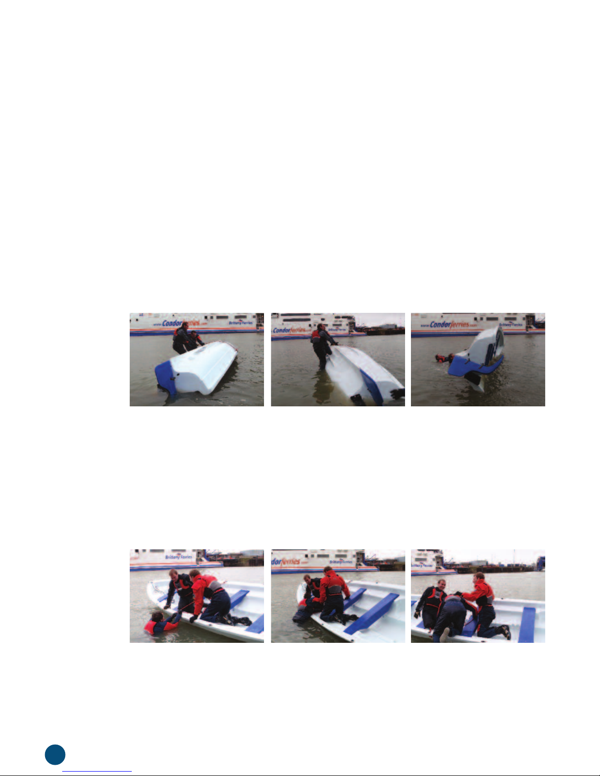
4.9 CAPSIZE RECOVERY
If you capsize, the crew can right the boat by standing on one
gunwale, holding onto the righting line fitted on the opposite gunwale
and leaning back (see photos). The easiest way to get back on the
boat after righting is for the crew to pull one gunwale down together,
to reduce the freeboard and then board one at a time.
4.10 MAN OVERBOARD PREVENTION AND RECOVERY
Avoid falling overboard by taking proper care, particularly when getting
on and off the boat and by not standing up in the boat. If a crew
member falls overboard, the rest of the crew should assist him or her
back onboard. Those not assisting the recovery should use their
weight to balance the boat to reduce freeboard one side.
Page 15

15
4.11 USE OF AN OUTBOARD MOTOR
Only outboards up to 3kw (4HP) should be used with the Trinity 500.
The maximum weight of any engine fitted is 25 kg. When an outboard
is fitted, remember to include its weight in the figure for total weight, as
listed in the table in section 4.3. The outboard should only be mounted
on the outboard bracket (available as an optional extra). Use the
outboard’s tiller to steer and unship (take off) the rudder to avoid
damaging the bottom of the rudder when turning to starboard.
The outboard should be operated in accordance with its Owner’s
Manual.
Use the outboard kill cord, where fitted, with the free end attached
securely to the
coxswain.
4.12 STARTING THE OUTBOARD ENGINE
If the outboard engine is fitted with a clutch, only start the engine with
the clutch disengaged/engine in neutral gear. When starting an engine
without a clutch, warn the crew to hold on and be ready for the boat
to move suddenly, before starting the outboard.
4.13 RISK OF FIRE OR EXPLOSION
There is a risk of fire or explosion from the petrol carried with an
outboard motor. If possible, only carry petrol in the integral tank of the
outboard. If this is not possible, carry spare fuel only in suitably marked
metal or purpose designed plastic petrol cans. No-one should smoke
in and around the boat when either the outboard’s tank or a spare fuel
container is open, or if petrol is spilled in the boat.
4.14 FIRE FIGHTING EQUIPMENT
When an outboard is used, a fire extinguisher suitable for use on liquid
fuel fires should be carried in the boat.
Page 16

16
5. HANDLING
5.1 STRETCHERS
The stretchers should be adjusted to the size of the oarsman so that
the oarsman sits comfortably on the thwart with their feet against the
stretcher and their legs straight or slightly bent.
5.2 HANDLING IN ACCORDANCE WITH WATER CONDITIONS
Always adjust the speed and direction of the boat to the sea
conditions. In particular, breaking waves are particularly dangerous and
should be avoided.
5.3 HANDLING UNDER OARS
The key to efficient and enjoyable rowing is good timing. The crew
should work together in perfect time, with oars entering and leaving
the water exactly together. The crew take their timing from the stroke,
who should row with as steady a rhythm as possible.
5.4 HOLDING WATER
When holding water to slow or stop the boat, the crew should not
immediately put their oars in the water with the blades squared, which
can be hazardous when the boat is moving fast. First inset the oars in
the water with blades
feathered and gradually square them as the
boat slows.
5.5 TOWING
When being towed, the tow line should be secured to the bow cleat.
To prevent the risk of chafe damage to the hull, secure the tow by a
two legged bridle led through both bow fairleads to the bow cleat.
Take care that the bridle or tow rope does not chafe on the plastic of
the hull.
Page 17

17
5.6 ANCHORING AND MOORING
When anchoring, lead the anchor warp through a bow fairlead and
secure it to the bow cleat. If anchoring in a current, tidal stream or
wind, which would cause the boat to yaw while at anchor, secure the
warp to the mooring loop in the bow tube so as to minimize the risk of
damage to the hull by chafe. When lying to a swinging mooring,
secure the boat by the mooring loop through the bow tube.
5.7 HANDLING UNDER OUTBOARD MOTOR
The Trinity 500 handles under outboard much as it does under oars,
but will be capable of a slightly higher speed. When travelling at speed
under outboard, avoid sudden bold movements of the tiller. It may be
necessary to reduce your speed when motoring into a head sea to
avoid shipping waves into the boat. Many small outboards suitable for
this boat are not fitted with a clutch or reverse gear. Care should be
taken when manoeuvring the boat astern as this causes a tendency
to yaw.
5.8 TRAILING
When securing the Trinity 500 to a road trailer, secure the rope from
the trailer to the mooring loop. Check that the road bed or trailer is
capable of taking the combined weight of the boat and launching
trolley (272 kg). The weight of the trailer, launching trolley and boat
should not exceed the towing limit for the towing vehicle, as given in
the vehicle’s owner’s manual. Always ensure that the trailer is properly
secured to the towing vehicle, including attaching the trailer’s
breakaway safety lanyard, where fitted.
The best type of trailer to use for a Trinity 500 is a road base, which
can take the boat on its launching trolley. Use of the launching trolley
ensures that the boat is always properly supported and allows the
boat and trolley to be loaded without the need to immerse the trailer
wheels in the water.
Page 18

18
6. CARE AND MAINTENANCE OF
YOUR TRINITY 500
Always maintain your boat properly and make allowance for the
deterioration that will occur in time and as a result of heavy use.
Use trained and competent people for maintenance, fixing or
modifications. Changes that may affect the safety characteristics of
the boat should be assessed, executed and documented by
competent people. The boat builder cannot be held responsible for
modifications that are not approved.
Any boat, no matter how strong, can be severely damaged if not used
properly. This is not compatible with safe boating.
6.1 BOAT CARE
The plastic hull of the Trinity 500 is designed to be as nearly
maintenance-free as possible. However, the plastic is vulnerable to
chafe and to degradation over time by ultra violet light from sunshine.
Avoid chafe on the plastic with care and good seamanship, particularly
by ensuring that warps and towing ropes are led through the fairleads
provided, or to the mooring loop. Minimize the effect of ultra violet light
by keeping the boat out of direct sunlight and by using a cover when it
is not in use.
6.2 BOAT STORAGE
Store the Trinity 500 on its launching trolley, with the bung out, and out
of direct sunlight when it is not afloat. This will minimize any tendency
of the boat to deform in direct sunlight, due to softening of the plastic.
When more than one Trinity 500 is kept in a single location, a stacking
kit is available as an optional extra, to allow the boats to be stacked
safely. Only one stacking kit may be used per launching trolley and
boats may be stacked no more than two high. Protect the boat from
direct sunlight, dirt, and bird and tree deposits by using a cover.
Page 19

19
6.3 FITTINGS
The cleats, fairleads, thwarts, pintles, gudgeons and outboard motor
bracket are screwed into mounting pieces moulded into the boat and
can be easily replaced if worn or damaged. The mounting pieces to
which they are screwed may only be repaired using plastic welding
equipment. Glue will not generally stick to the plastic of the boat.
6.4 CLEANING
Your Trinity 500 may be cleaned with any recognised boat cleaning
agent. Avoid using oily or abrasive substances. Citrus based cleaners
are excellent for marine cleaning purposes and are safe to use.
Household cleaners should be used sparingly and not discharged into
any waterways. Never mix cleaners and work in a well ventilated area.
Read labels and instructions before use to avoid products which may
damage the boat. Do not use products that contain phosphates,
chlorine, solvents, non-biodegradable or petroleum based products.
6.5 REPAIRS
A scratch that penetrates into the second (foam) layer of plastic should
be repaired before the boat is used again. A split which penetrates all
3 layers of plastic should to be repaired by a boat repairer equipped
with a plastic welding tool.
Page 20

20
7. EC CONFORMITY
The Trinity 500 complies with the EU Directive for Recreational Craft
(RCD) which sets safety requirements for recreational boats sold in
Europe. Each Trinity 500 carries the CE mark to indicate this
compliance. The CE Mark is on the Builder’s Plate at the stern.
The Builders Plate also includes important safety information which
is described in detail in paragraphs 4.4 of this manual.
Compliance with the EU Directive for Recreational Craft (RCD) is also
demonstrated by the EC Declaration of Conformity which follows:
Declaration of Conformity of Recreational Craft with the
Design, Construction and Noise Emission requirements of
Directive 94/25/EC as amended by Directive 2003/44/EC
Name of Craft manufacturer: Marine Society & Sea Cadets
Address: 202 Lambeth Road
London SE1 7JW
United Kingdom
Name of Notified Body for design and construction assessment:
Address: Royal Yachting Association
Ensign Way
Hamble
Southampton SO31 4YA
United Kingdom
EC type-examination
Certificate number: 613/09
Date: 2010/March /29
Module used for
construction assessment: B and C
Page 21
21
DESCRIPTION OF CRAFT
Craft Identification Number:
Brand name of craft: Trinity 500
Type of craft: Pulling boat
Type of hull: Monohull
Deck: Open
Construction material: Rotation moulded plastic
Maximum Design Category D
Type of main propulsion: Oars
Type of engine: Outboard
Maximum Recommended Engine Power: 3 kw
Length of hull Lh: 5.5 m
Beam of hull Bh: 1.76 m
Draught T: 0.45 m
Signature: Date: 14 April 2010
Patrick Balfour
Staff Officer Operations
G B T B P . . . . . B 0 1 0
Page 22

22
Essential requirements
(reference to relevant articles in
Annex IA & IC of the Directive)
General requirements (2) X EN ISO 8666:2002 *
Craft Identification Number – CIN (2.1) X EN ISO 10087:2006 *
Builder’s Plate (2.2) X EN ISO 14945:2004
Owner’s manual (2.5) X EN ISO10240:2004
Integrity and structural requirements (3)
Structure (3.1) X EN ISO 12215-2:2002
Stability and freeboard (3.2) X EN ISO 12217-1:2002
Buoyancy and floatation (3.3) X EN ISO 14946:2001
Manufacturer’s maximum recommended load (3.6) X EN ISO 14946:2001
Anchoring, mooring and towing (3.9) X EN ISO 15084:2003
Standards
Other normative
document/method
Technical file
Please specify in more detail
(*: Mandatory Standards)
Standards applied:
Page 23

23
8. IDENTIFICATION
Each Trinity 500 is identified by the Craft Identification Number, a serial
number, unique to each boat, stamped on the starboard side of the
transom. This number is also shown in the EC Declaration of
Conformity in section 7 of this manual.
9. WARRANTY
The Trinity 500 has one year’s warranty against faulty materials and
manufacture. This warranty may be invalidated if the boat is used other
than in accordance with this manual. In case of warranty claims,
contact the supplier of the boat.
Page 24

24
10. GLOSSARY
Aft Towards the stern end of the boat
Backing down Rowing backwards by pushing rather than
pulling the oars
Backwatering Rowing backwards as above. See backing
down
Bilge The lowest point of the inside of the boat
where water will collect
Bilge keel The moulded rails either side of the keel,
designed to reduce rolling and as aids to
righting the boat if capsized
Blade The flattened end of the oar, opposite the
oar handle
Bow The forward end of the boat, also the
oarsman sitting on the thwart nearest
the bow
Bow tube A reinforced tube moulded in the bow of
the boat used to prevent chafe of the
plastic when moored to a buoy or when
being towed
Bridle A rope which divides the pull of a tow rope
between 2 fittings, to reduce the strain on
both of them
Builders Plate A sticker at the stern indicating compliance
with European Community regulations and
giving basic safety information
Button The device fixed to the
collar which locates
the oar in the
rowlock
CE Mark A mark indicating compliance with
European safety regulations
Cleat A device for securing a rope to the boat
Page 25

25
Collar The plastic sleeve on the oar which carries
the button
Coxswain The person in charge of the boat and crew,
who sits at the stern and steers.
Crutch A device for holding the oar, see also
Rowlock
Draft The depth of the deepest part of the boat
below the water
Fairlead A device through which ropes are led to
avoid chafing the plastic
Feathered The oar blade held horizontal, parallel with
the water to reduce wind resistance or
when holding water in a fast moving boat
Fender suspension points The points to which fenders are secured
Fore and aft trim The angle at which the boat floats compared
to the horizontal as seen from the side
Forward Toward the bow of the boat
Freeboard The distance between the lowest point of
the gunwale and the water
Gudgeon A socket which fits over a
pintle
Gunwale The top of the boat’s sides, where they
meet the deck
Heel Where the boat leans to one side, seen
from one end
Holding water Slowing and stopping the boat by inserting
the oars in the water, with the crew bracing
against the boat’s momentum
Keel The external ridge running from
bow
to stern
Kill cord A lanyard attached at one end to a
cut-off switch on an outboard motor and
secured at the other to the helmsman.
It will automatically stop the motor if pulled
from the cut-off switch if the helmsman
falls overboard
Page 26

26
Length The length of the boat measured
horizontally from the extremity of the
bow to the aftermost part of the stern
Level trim The boat floating horizontally, as seen
from the side
Mooring A device, usually consisting of a buoy,
riser and ground tackle, to which a
boat may be secured away from the
bank or shore
Mooring loop A looped piece of rope led through the
bow tube as an attachment for towrope,
mooring warp or trailer rope
Moulding A moulded component
Oar Handle The part of the oar held in the hands
when rowing
Pintles Vertical pins on the rudder and transom
which fit into gudgeons and on which the
rudder turns
Pulling Rowing a boat with fixed seats
Port The left hand side of a boat, when facing
forward
Quarter The extremities of the transom, where it
joins the sides
Righting line A line fitted to both
gunwales to assist the
crew to right the boat after a capsize
Rotation moulded The technique of moulding plastic items in
a heated rotating mould
Rowlock A
crutch; a device for holding an oar
Sculling First meaning: Propelling a boat with an oar
(scull) in each hand
Sculling Alternative meaning: Propelling a boat with
a single oar worked in a sculling notch or
crutch at the stern
Page 27

27
Sea Cadets A national youth movement run by the
Marine Society and Sea Cadets, the largest
maritime charity in the United Kingdom
Squared The oar blade held vertically, at right angles
to the water, as used when taking a stroke
Stability The tendency of a boat to remain upright
and level
Starboard The right hand side of a boat, when facing
forward
Stern The aft end of the boat, including the
transom and the part of the boat
immediately forward of it.
Stretcher The adjustable tube against which the
oarsman braces the feet when taking a
stroke
Stroke The oarsman sitting on the aftermost
thwart
Trim The angle at which the boat floats,
compared to the horizontal, seen from
the side
Thwart Seat, fixed in the boat.
Transom The flat, vertical
aft end of the boat
Upright A stable condition where the boat floats
with no
heel to port or starboard, seen from
one end of the boat
Warp A rope of suitable size and length to secure
a boat alongside a pontoon or jetty, or to
an anchor
Yaw The weaving of the boat due to wind or
current at anchor or mooring.
Page 28

A charity registered in England and Wales
313013 and in Scotland SC037808
ms-sc.org
 Loading...