

MSSC Smart-Jet BLUE User Manual

T H E R M A L I N K J E T C O D E R
USER’S MANUAL
Pro Pack Solutions, Inc.
770-554-1187

SAFETY INFORMATION ................................................................................................................................................ 4
PRODUCT WARRANTY ................................................................................................................................................. 4
ABOUT MACHINE ........................................................................................................................................................ 4
TECHNICAL SPECIFICATIONS ........................................................................................................................................... 5
Machine details .......................................................................................................................................................... 5
Keyboard .................................................................................................................................................................... 5
Android devices .......................................................................................................................................................... 5
MACHINE OVERVIEW ...................................................................................................................................................... 6
Indicator LED .............................................................................................................................................................. 6
Connecting Port .......................................................................................................................................................... 7
Keyboard .................................................................................................................................................................... 7
Operation menu with keyboard ................................................................................................................................. 8
Operation menu with PC software ........................................................................................................................... 11
GETTING STARTED ..................................................................................................................................................... 17
INSTALLATION PROCEDURES ..................................................................................................................................... 18
MOUNTING BRACKETS .................................................................................................................................................. 18
EXTERNAL DEVICES CONNECTIONS ........................................................................................................................... 22
EXTERNAL SENSOR ........................................................................................................................................................ 22
ENCODER ...................................................................................................................................................................... 23
COMBINE EXTERNAL SENSOR AND ENCODER ............................................................................................................... 24
ALARM .......................................................................................................................................................................... 25
INPUT AND OUTPUT...................................................................................................................................................... 25
RS485 PROTOCOL ......................................................................................................................................................... 25
QUICK STARTUP ........................................................................................................................................................ 27
REQUIRED COMPONENTS ............................................................................................................................................. 27
Setup machine .......................................................................................................................................................... 27
Keyboard setup ......................................................................................................................................................... 28
Bluetooth setup (for connection to Android devices) ............................................................................................... 28
PC connection setup ................................................................................................................................................. 31
Setup external devices (Optional) ............................................................................................................................. 31
Create first messages ............................................................................................................................................... 31
KEYBOARD OPERATION ............................................................................................................................................. 33
MESSAGE ......................................................................................................................................................................... 33
OPERATION ...................................................................................................................................................................... 42
SETTINGS ......................................................................................................................................................................... 43
PC APPLICATION INTRODUCTION .............................................................................................................................. 54
SOFTWARE REQUIREMENT ................................................................................................................................................... 54
HARDWARE SETUP ............................................................................................................................................................. 54
SOFTWARE SETUP .............................................................................................................................................................. 54
Install application ..................................................................................................................................................... 54
Install driver .............................................................................................................................................................. 56
Install driver on Window 8 ....................................................................................................................................... 62
SOFTWARE USING .............................................................................................................................................................. 67

Printer Controller Interface ....................................................................................................................................... 67
Create new message ................................................................................................................................................ 67
APPENDIX.................................................................................................................................................................. 78
INK CARTRIDGES MAINTENANCE .................................................................................................................................. 78
Print head cleaning ................................................................................................................................................... 78
Wiping ...................................................................................................................................................................... 78
Important notes ........................................................................................................................................................ 79
Purging ..................................................................................................................................................................... 79
INK CARTRIDGE STORAGE PROCEDURE ........................................................................................................................ 80
Important handling cautions .................................................................................................................................... 80
UPDATE FIRMWARE INSTRUCTIONS ............................................................................................................................. 81
Prepare USB flash ..................................................................................................................................................... 81
Update firmware ...................................................................................................................................................... 82
Update logo .............................................................................................................................................................. 82
Update font .............................................................................................................................................................. 82
Machine default ....................................................................................................................................................... 83
TROUBLE SHOOTING ................................................................................................................................................. 83

SAFETY INFORMATION
Have to STOP machine before plug/ unplug cartridge.
Avoid using with the high voltage, strong impact to the coder.
Limit store the coder in the high dusty working environment.
The working temperature of the coder is 5oC – 50oC.
PRODUCT WARRANTY
The Product warranty for machine is effective for 12 months from delivery date. Brackets,
keyboard, power supply, and anti-shock mechanism are excluded from the warranty.
The warranty is VOID if:
Any non-original parts and unapproved OEM inks are used.
The product has been altered or modified without approval from us.
Print head damage is a result of improper installation.
Damage occurs from an accident, such as but not limited to, being dropped, being sprayed
with water or other liquids, caused by a natural disaster, caused by stocking or shipping
conditions.
Unapproved, wrong or unstable power supply is used.
ABOUT MACHINE
Thank you for purchasing the Smart-Jet BLUE Thermal Inkjet Coder, a product of MSSC LLC,
US. This printer is designed for packaging printing applications powered by HP Thermal Inkjet
Technology.
Machine boasts to be able to control via PC connection to print variable data and barcodes,
Bluetooth connection via mobile devices running on Android operating systems, and wireless
keyboard. Each option provides a full set of applications.
Machine produces crisp text, logos, variable data and barcodes on porous and non-porous media
by automatically recognizes aqueous and solvent inks and applies the appropriate printing
parameters.
The complete system includes one machine, power supply with On/Off switch, wireless keyboard,
mounting brackets and necessary software for PC and Bluetooth operations.
USER MANUAL V02 | Updated 18-Jan-2016 4

No
Description
Specifications
1
Model
Smart-Jet BLUE
2
Display
LCD 2.8” automatic rotation
3
Dimensions (Lx W x H)
107.5 x 74.5 x 83 mm / 4.23 x 2.93 x 3.27 in
4
Weight
450g
5
Power supply
AC 100V – 240V, 50/60Hz, 1.4A
6
Maximum power consumption
48W
7
Maximum printing resolution
600x600dpi
8
Print speed
76m/min@300x300dpi
9
Optical density
5 levels
10
Operation selection
PC, Wireless keyboard, Bluetooth
11
Message memory
100 messages
12
Ink solution
Aqueous and Solvent
13
Menu language
Multiple / selectable
14
Printable characters
Windows True Fonts
15
No. of lines
Maximum 6 lines
16
Character height
Maximum 12.7mm / 0.5”
17
Printability
Alphanumeric, logos, date/time, expiry date, Julian date,
shift code, data and barcodes
18
Operating temperature
50C – 500C
19
External connections
External sensor, encoder, alarm kit, etc.…
TECHNICAL SPECIFICATIONS
Machine details
Keyboard
The Machine is currently compatible with all wireless USB 2.0 keyboards available in the market.
Android devices
Control machine via Bluetooth connection by using Android devices from 4.0 up to.
USER MANUAL V02 | Updated 18-Jan-2016 5
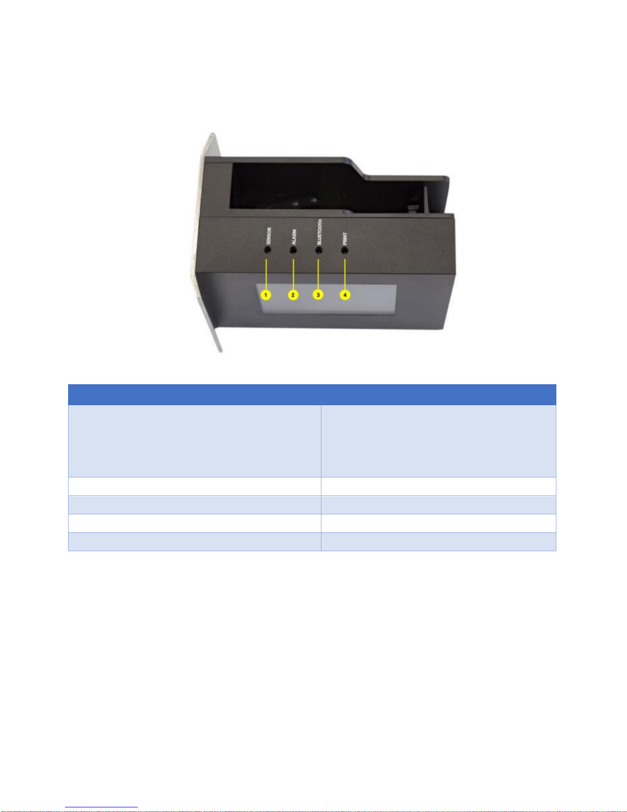
MACHINE OVERVIEW
Items
Detail
[1] Sensors
Default setting is don’t recognize black conveyor
Internal sensor: Red light.
External sensor: Green light.
Sensor is activated when receives signals
[2] Error
Reports errors during operation.
[3] Bluetooth/PC
Remains ON when being connected
[4] Printing Status
Remains ON when it’s on printing mode.
[5] Ink Low
Remains ON to indicate ink low.
Indicator LED
USER MANUAL V02 | Updated 18-Jan-2016 6

Items
Detail
[1] USB FLASH
USB 2.0 flash for updating firmware, fonts and logo
[2] USB KEYBOARD
For USB 2.0 wireless keyboard receiver
[3] USB PC PORT
For PC connection with USB 2.0 cable A-B
[4] DB15 EXTENDED PORT
Extend port for external sensor, encoder, alarm, etc…
[5] 12VDC PORT
Power supply
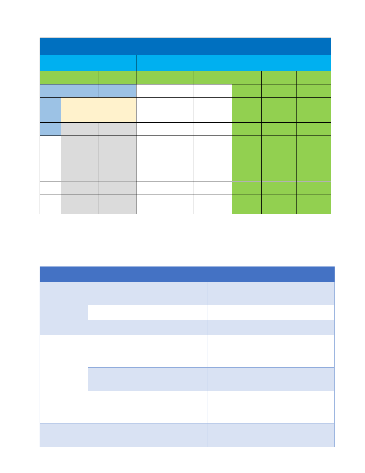
No
Key
Use
1
Enter
Confirm, save or apply
2
ESC
Go to previous session
3
/
Move your cursor to left/right
4
/
Move your cursor up/down
5
Shift
Press and hold “Shift” to input capitalized characters
6
Insert
Press “Insert” to insert Symbol, Logo, Counter, Date, Expired, Time,
String, Barcode, and Shift into the message
7
Backspace
Delete your message from the left
8
Tab
Move your cursor faster
9
Home/End
Move your cursor to Home/End
Connecting Port
Keyboard
USER MANUAL V02 | Updated 18-Jan-2016 7
Main Menu
Message
Operation
Setting
Open
Create new
Information
Purge
Start/Stop
Connect PC
Speed
Resolution
Density
Use
Select font
Select size
Delay
Cartridge
Update logo
Edit
Insert Menu
(Popup menu when press Inset)
String
Random Jet
Print Side
Delete
Symbol
Logo
Sensor
Direction
Print Mode
Counter
Date
Unit
Bluetooth
Update Font
Expired
Time
Roll over
hour
System
Clock
Rotate
String
Barcode
Password
Default
Language
Shift Code
IO Signal
Coder Name
RS485
LCD
Backlight
Reset
About
Menu
Sub Menu
Description
Open
Use
Use the existing messages on the
machine memory for printing.
Edit
Edit the existing message.
Delete
Delete existing messages.
Create new
Select font
Select kind of font you need to use on
messages. Support two kind of font:
Upper Case font and Normal font
Select size
Select size of messages: support up to 6
sizes.
Insert menu (Symbol, Logo, Counter,
Date, Expired, Time, String, Barcode,
Shift Code)
Insert some needed component to your
messages.
Information
Show all information needed to monitor
your printing process.
Operation menu with keyboard
From the main screen of machine, use arrow keys to move the cursor to the desired
object. Press Enter to save and apply settings. Otherwise, press ESC.
Message
USER MANUAL V02 | Updated 18-Jan-2016 8
Operation
Menu
Description
Start / Stop
Start or Stop printing job. Combine and press CTRL + SHIFT + ENTER on
keyboard to fast Start / Stop print.
Purge
All of nozzle on cartridge will push out ink. After purged you will see 2 lines of
ink on substrate.
Connect PC /
Disconnect PC
Connect or Disconnect machine from PC.
Please stop print first, before go to Connect PC menu.
Menu
Description
Speed
Set print speed for the machine or select to enable encoder.
Resolution
Set your desired resolution.
Density
Set optical density of the print.
Delay
Set the distance since the sensor receives signal to the start of printing. Or
the delay distance after printer take a print command.
Cartridge
Display the current level of ink in the cartridge. Or kind of current cartridge is
plugged to machine.
Update Logo
Update logo or image from USB to the machine memory.
String
Set the chain of data to insert into the print.
Random Jet
Prevents the print head from clogging due to the extended down time
between prints. This will be useful when you print on Solvent base ink with
decap time is low.
Print Side
Select nozzle side on the cartridge: Odd, Even, or Auto switch
Sensor
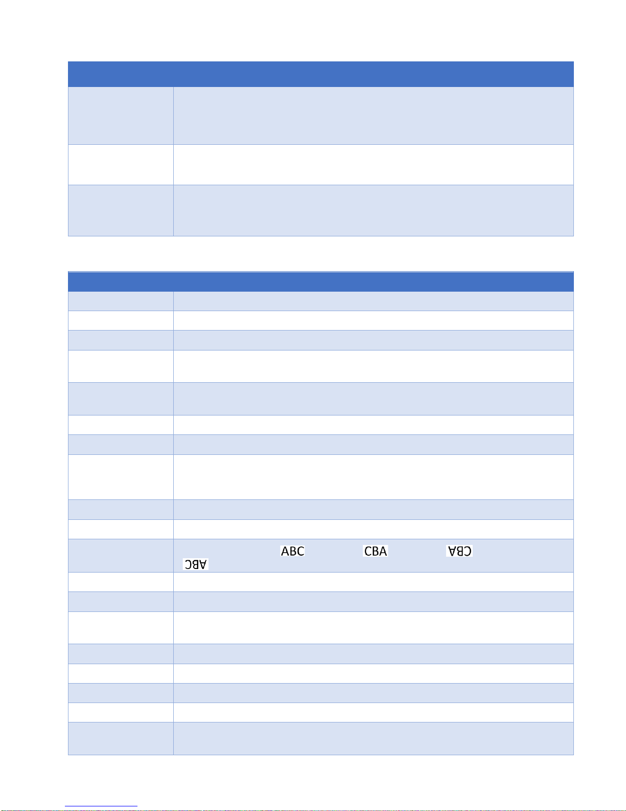
Select External or Internal sensor.
Directions
set print direction: : left right, : right left, : reverse left right,
: reverse right left.
Print Mode
Select printing mode: Sensor mode and Continuous mode.
Unit
select desired measurement inch/mm.
Bluetooth
Turn on Bluetooth connection to help you can search the printer via app on
Android devices.
Update Fonts
Update different font sizes for machine via USB flash contain of full firmware.
Rollover hour
Set different date depending on specific production hour.
System clock
Set time and date for your system clock.
Rotate
Select your screen modes: Auto-rotate or Lock rotate.
Password
Set to authorize different level of users, or to protect the machine from
unauthorized users.
Settings
USER MANUAL V02 | Updated 18-Jan-2016 9

Default
Reset machine to factory default.
Language
Select your interface language. Or add more interface language from USB
flash.
IO signals
The extend button to re-start machine. This will help in some special case.
Custom string
Update the custom strings via USB flash that are created from application on
PC. This useful to printing with any language without connecting to PC.
Coder name
This name will be showed once you use the Android app to search or
connect.
RS485
Enable the RS485 protocol on machine. To help you able to control multiple
printer by one Controller (PLC, PC, Laptop…) on RS485 network.
LCD Backlight
Adjust the time that turn on the light of screen. Your screen will become black
but all activity still working. Turn on screen by press any key on keyboard.
Reset
Reset the memory of Counter variable on message. The memory of Counter
will help you save the current value of Counter event you stop print or
machine is turned off.
About
Display current firmware version on printer and allow your update new
firmware to machine.
USER MANUAL V02 | Updated 18-Jan-2016 10

PC Application Menu
Printer Control Screen
Designing Screen
Tools
About
Print Head
Setup
Printer
Setup
Printing
Status
New
Template
Edit
Template
Open
Template
Purge
Ink Cost
Switch
nozzle
Unit
Connection
Status
Save
Template
Export
Template
to TIFF
Delete
Event Log
Convert
Logo
Random
Jet
Direction
Speed m/min
Cut
Copy
Paste
Encoder
Density
Page Index
Mouse
Selected
Hand
Selected
Shape
Printer
Controller
Resolution
DPI
Start Page /
End Page
Text
Insert
Serial
Number
Insert
Shift Code
Insert
Print
Printing
Mode
Ink Level
Image
Insert
Pause
Sensor
Setup
No Repeat
Data
Stop
Operation menu with PC software
Printer Control Screen
Setting all printing parameters for the message before start printing.
Be sure to stop the printing mode before setting the parameters.
Print Head Setup
Switch Nozzle
Select nozzle sides, ODD or EVEN.
Turn on ODD to print on the odd side (with 300x300dpi).
Turn on EVEN to print on the even side (with 300x300dpi).
Auto Switch Nozzle
Select ON for automatically changing nozzles between ODD and EVEN. And then select the number
of changing. Otherwise, select OFF.
Random Jet
Periodically purge to clean the print head.
USER MANUAL V02 | Updated 18-Jan-2016 11

Turn ON Status and set the time for purging in the Time by click up or down at or input the
desired value.
This value is adjustable from 5s to 1,000s.
Encoder
Encoder is recommended to optimize maximum print quality.
Turn ON Encoder to operate Machine with encoder. Print speed of Machine will be automatically
synchronized with conveyor speed.
Turn OFF Encoder to disable encoder. Input your desired speed at Speed to synchronize with the
speed of the conveyor.
Max Speed: shows the maximum speed you can achieve with the current resolution and density.
NOTES:
Ensure your encoder is working if it is ON and can detect the objects.
To make a test print without conveyor, turn OFF encoder.
Printer Setup
Unit
Select your measurement Inches or Millimeters.
Direction
Select your print direction Left to Right or Right to Left.
Select Rotate View to print upside down.
Rotate View
Upside down the current design of your message.
Density
Select your desired optical density. There are 5 levels to select.
Resolution DPI
Select your desired resolution
Printing Mode
Select your printing mode: Continuous Mode or Sensor Mode.
Sensor Mode
Machine prints when sensor is triggered.
Select Internal to print with a built-in sensor on Machine.
Set Delay before and Delay after print to have your message printed at the desired position.
Select External to print with external sensor
USER MANUAL V02 | Updated 18-Jan-2016 12
Input distance from external sensor to the print head, set Delay before and Delay after print to
have your message printed at the desired position.
Continuous Mode
Machine will print continuously when a sensor is triggered for the first time.
When Continue mode is applied, distance between the messages on the same object should to be
set.
Go to Fixed Length to input the value or select the value by click up or down at button .
Go to Repeat All and select Times to input how many prints to be repeated. Otherwise, select
Unlimited.
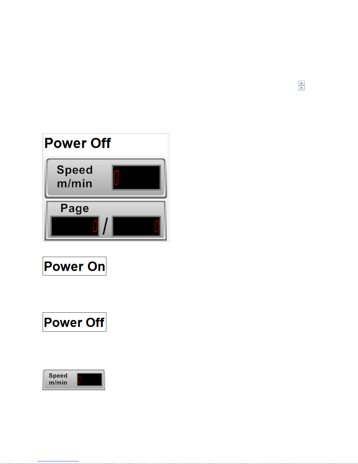
Printing Status
Machine is connected to PC.
Machine is disconnected from PC.
Displays the current speed of conveyor synchronized by encoder.
USER MANUAL V02 | Updated 18-Jan-2016 13
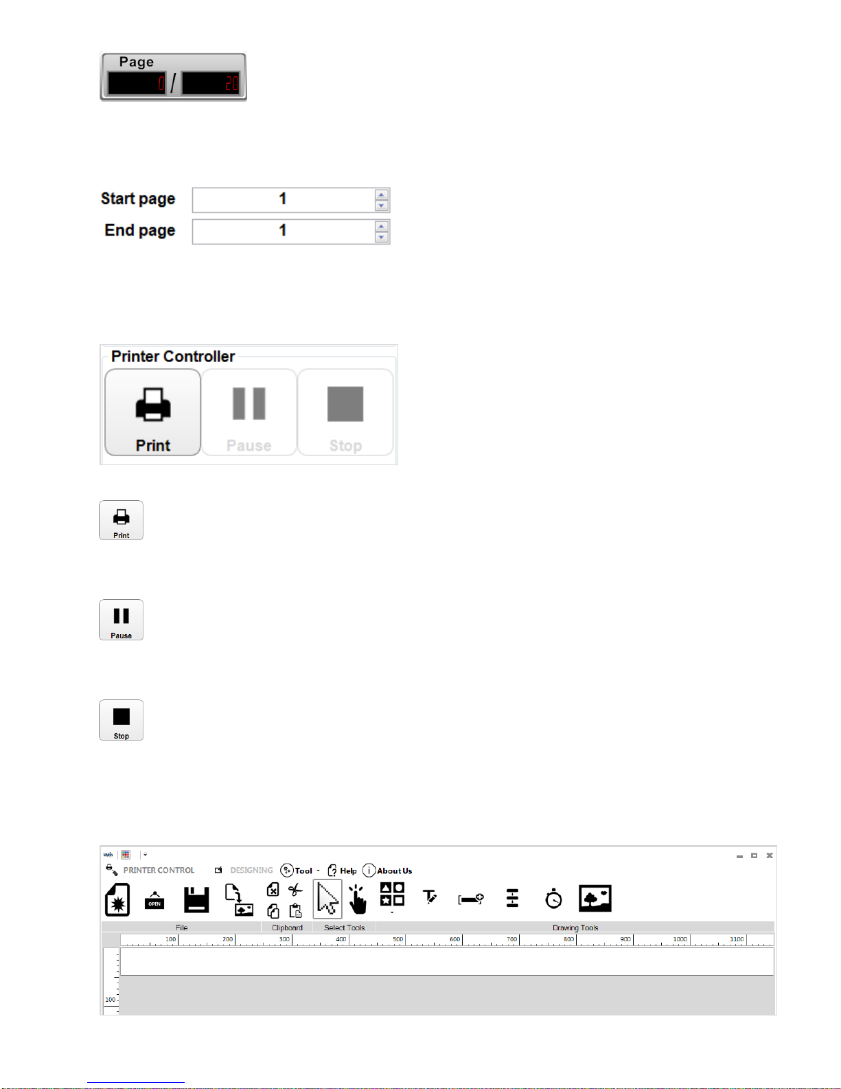
Displays the number of pages printed (left) per the total pages to print (right).
Select page to start / end printing, apply for counter, barcode. The data will continue to be printed
from the start page.
Printer Controller
Print: Select to print
Pause: Select to temporary stop printing
Stop: stop printing.
This must be applied before adjusting parameters or editing the message.
Designing messages
USER MANUAL V02 | Updated 18-Jan-2016 14
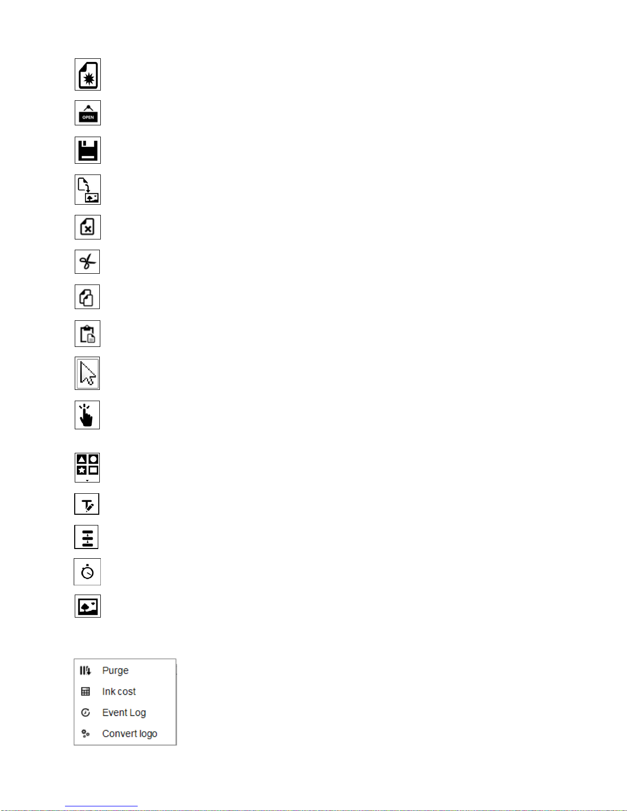
New template: Create new message with free template design.
Open: Open message from PC.
Save template: Save message to PC.
Export to .tiff files: Export message in Tiff format.
Delete: Delete object.
Cut: Cut object.
Copy: Copy object.
Paste: Paste object.
Select Tool: Select to function and edit each object on the message.
Hand Pan: Move designing area to right/left to function on the hidden area in case your
message is not fully displayed on the screen.
Shapes: Select image to insert into message: Line, Rectangle, Square, Circle and Oval.
Static Text: Insert characters and barcodes.
Serial Number: Insert counter.
Shift Code: insert shift code.
Image: Insert image or logo.
Tools
USER MANUAL V02 | Updated 18-Jan-2016 15

Purge: all of nozzle on cartridge will push out some ink. This will help clean all cartridge.
Ink Cost: calculate number of printing job, ink price, price for each print.
Event Log: view all of action that user did on application.
Convert logo: use to convert photo / image / logo / text to HEX file and update to the printers.
USER MANUAL V02 | Updated 18-Jan-2016 16

GETTING STARTED
Install the machine on your conveyor according to the installation instructions.
See the Quick Installation Guide (included inside package) for more information.
Set print direction and appropriate throw distance to obtain best print quality (1-3 mm).
Insert ink cartridge.
Plug the power cord into an appropriate power source to start up the machine.
Insert keyboard receiver to keyboard port, turn on wireless keyboard.
USER MANUAL V02 | Updated 18-Jan-2016 17
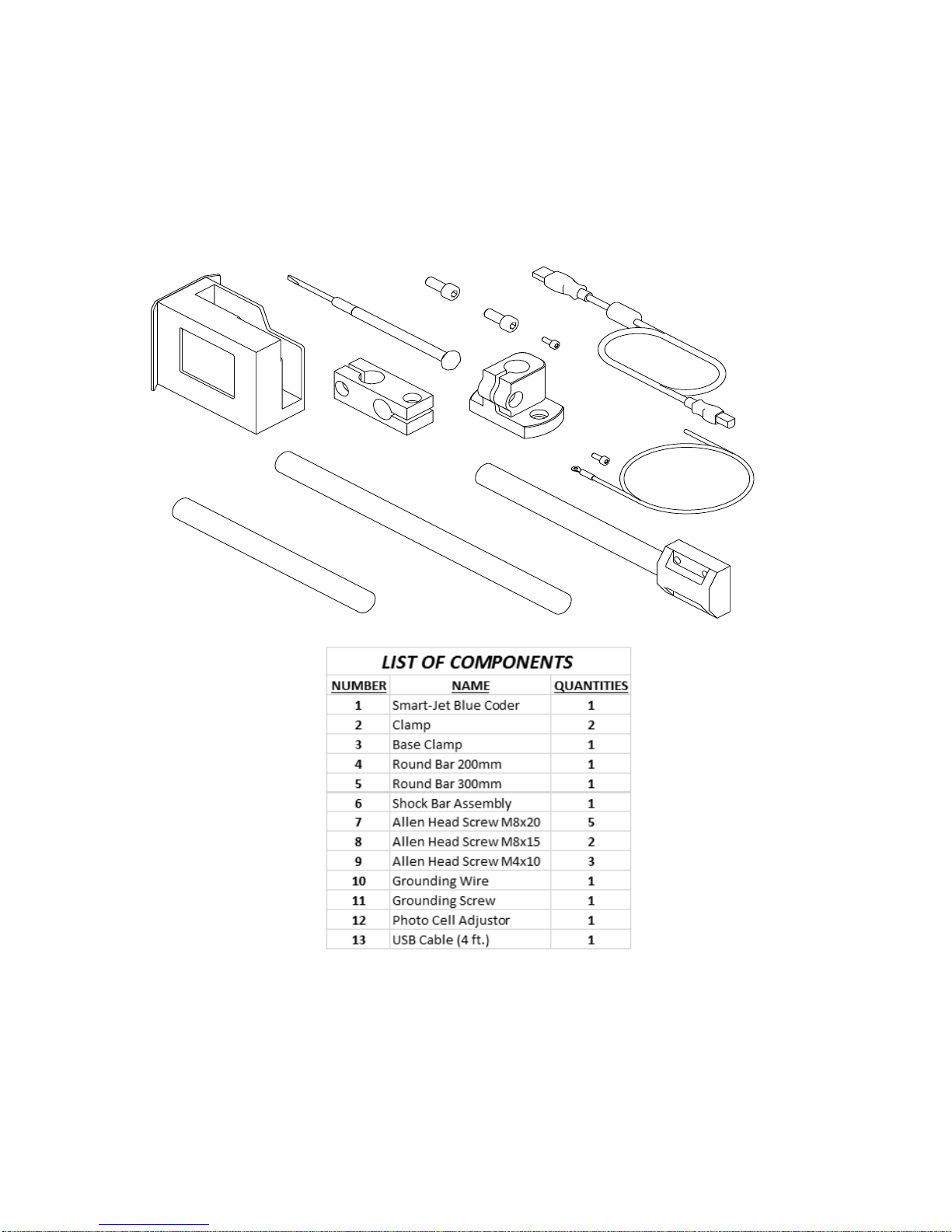
1
2
3
4
5
6
7
8
9
10
11
12
13
INSTALLATION PROCEDURES
MOUNTING BRACKETS
Step 1
Skid plate adjust depending on direction of your production line.
Select direction to mount machine on the conveyor. Skid plate can be assembled as A or B position
depending on the direction of the products on the conveyor.
Default machine will be set at B position.
USER MANUAL V02 | Updated 18-Jan-2016 18
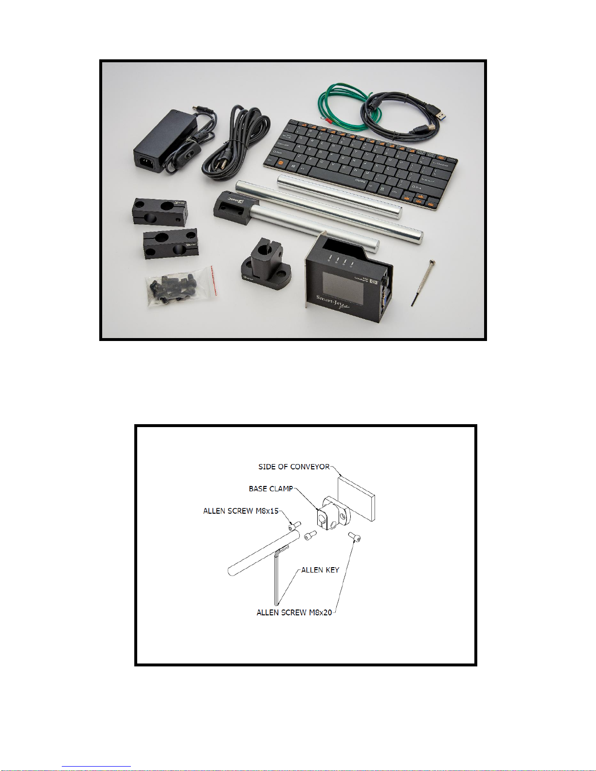
Step 1: Installing the clamps to the side of the conveyor
USER MANUAL V02 | Updated 18-Jan-2016 19
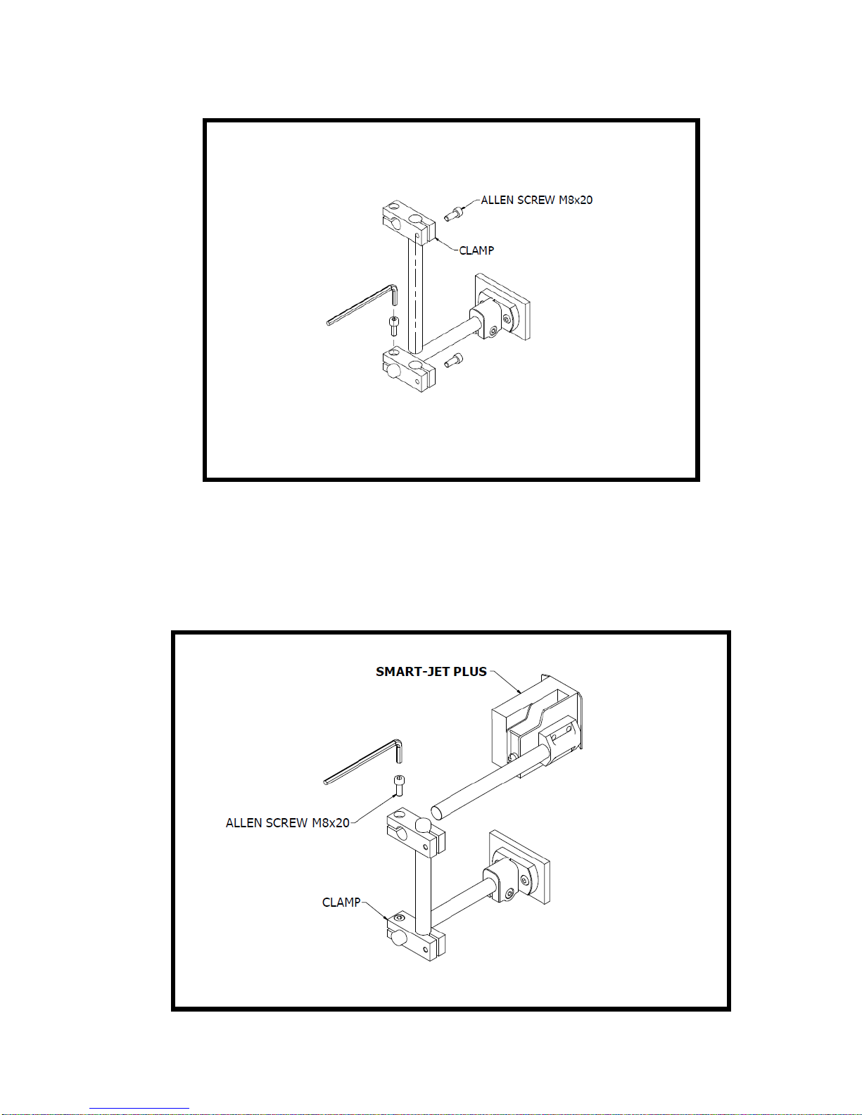
Step 2: Installing the clamps to the round bar
MOUNTING OPTIONS
Select the suitable bar length
Horizontal setup
USER MANUAL V02 | Updated 18-Jan-2016 20
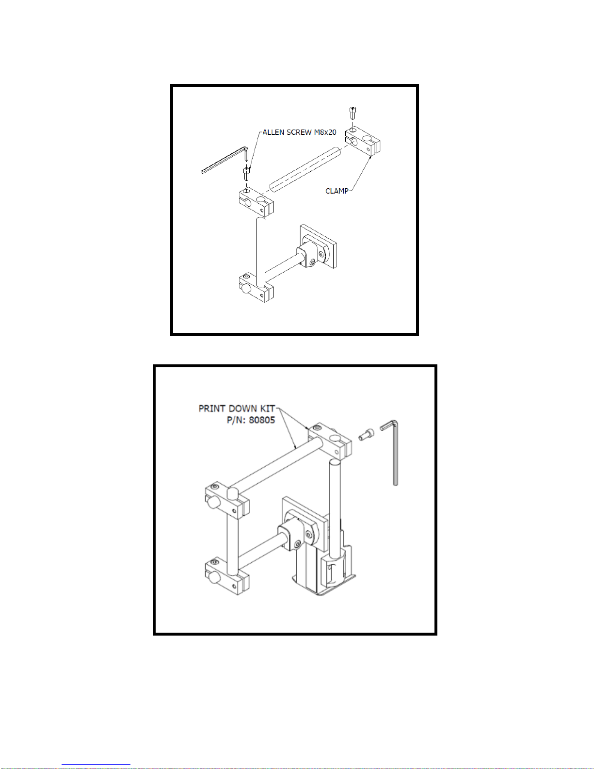
Vertical setup
Step 1:
Step 2:
NOTES:
Make sure the brackets are mounted firmly to avoid vibration and sway of the print head. This
will affect the print quality.
USER MANUAL V02 | Updated 18-Jan-2016 21
EXTERNAL DEVICES CONNECTIONS
NOTES:
Machine is able to operate with External Sensor, Encoder, Alarm at a time. Consult your
supplier for further supports on the settings and connections.
To connect machine with External Sensor, Encoder, Alarm, etc…, additional connector DB15
(male) will be required.
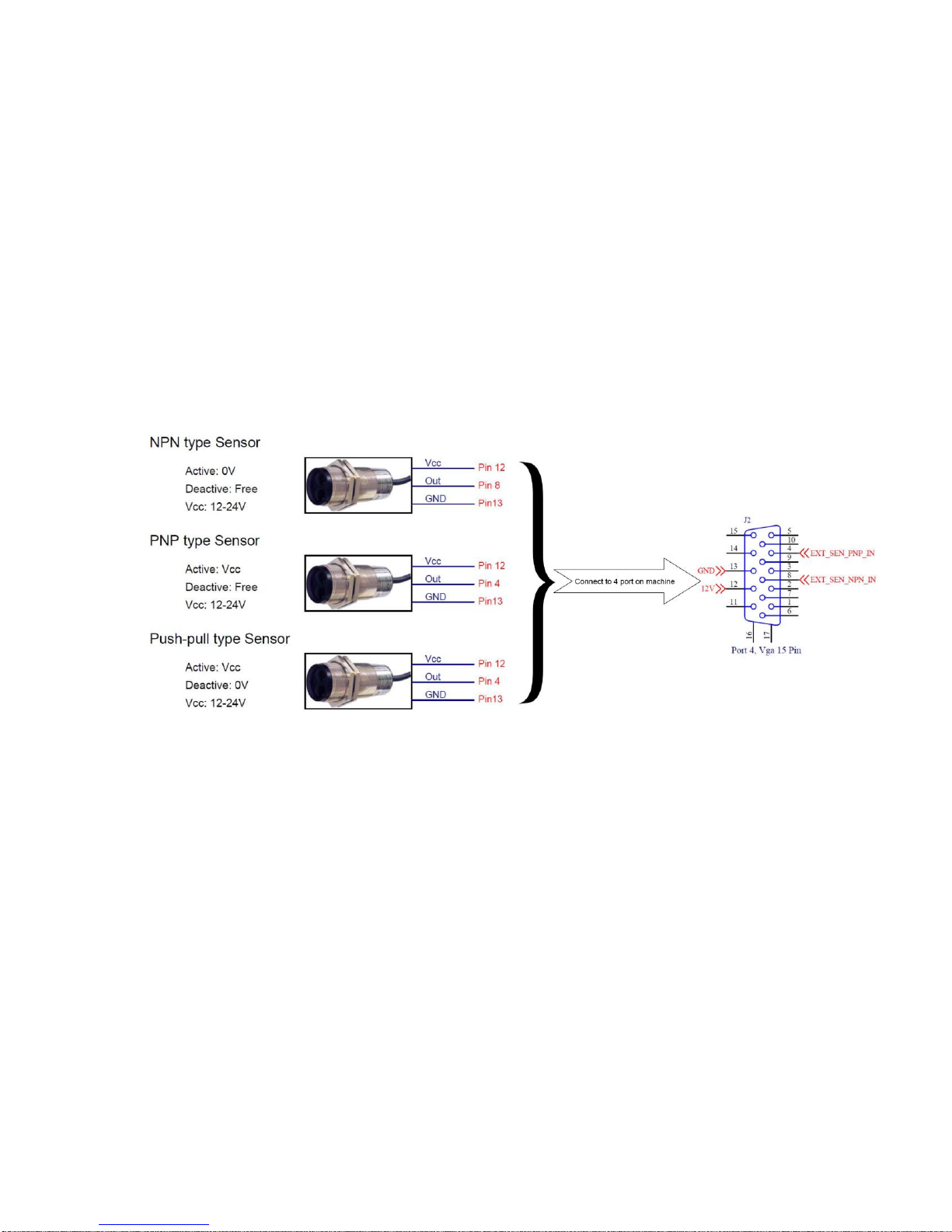
EXTERNAL SENSOR
Machine supports NPN, PNP and Push-pull sensor types.
Connect sensor using power supply on machine.
Connect sensor to machine using external power supply. Below demonstration is for external
power supply of 5V.
USER MANUAL V02 | Updated 18-Jan-2016 22
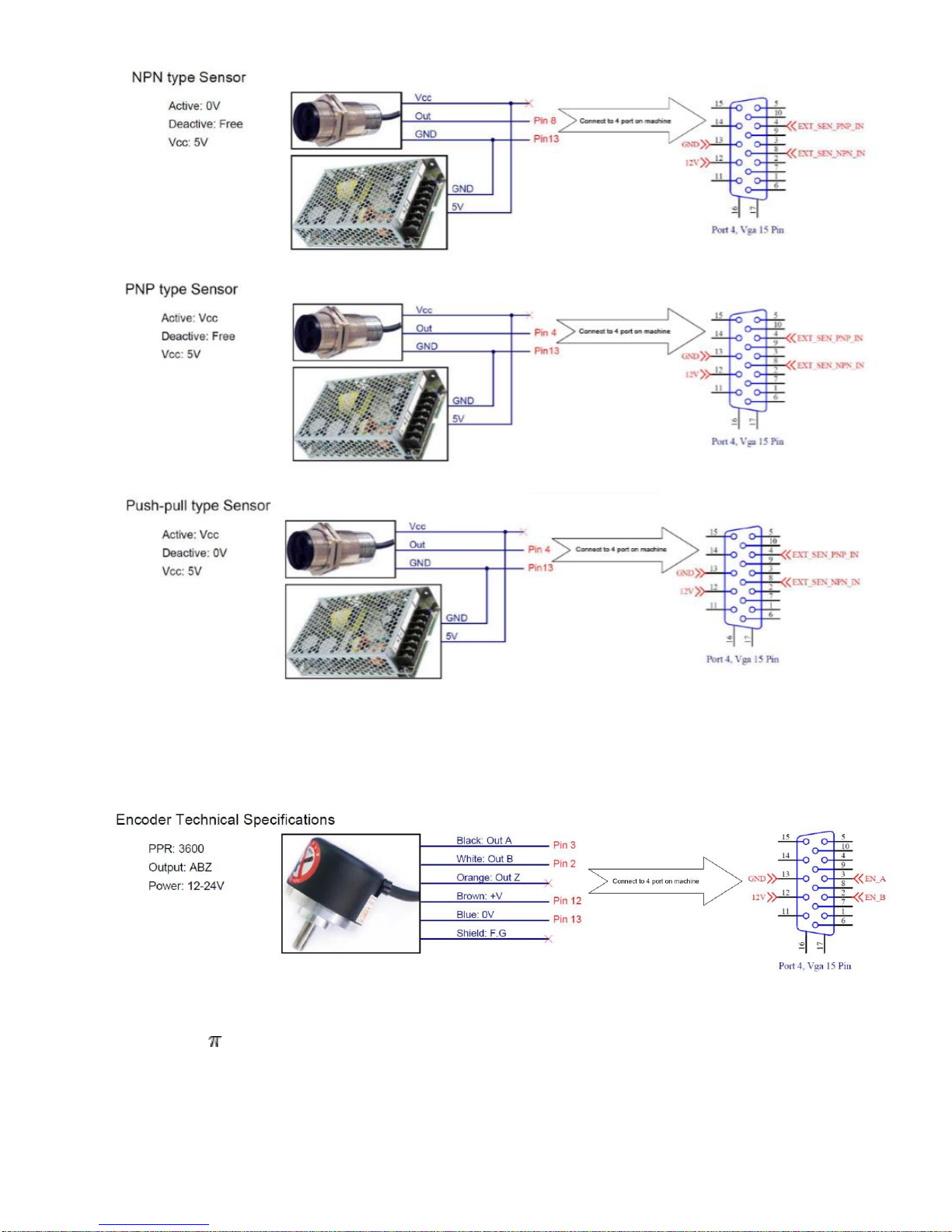
ENCODER
An encoder is recommended to ensure the best print quality regardless the inconsistent speed of
conveyor.
To calculate wheel diameter (D) depend on resolution (R) is:
D = R/( x 600) (inches).
Example: Encoder has R = 3600 (PPR),
D = 1.90985 inches ~ 48.5 mm.
USER MANUAL V02 | Updated 18-Jan-2016 23
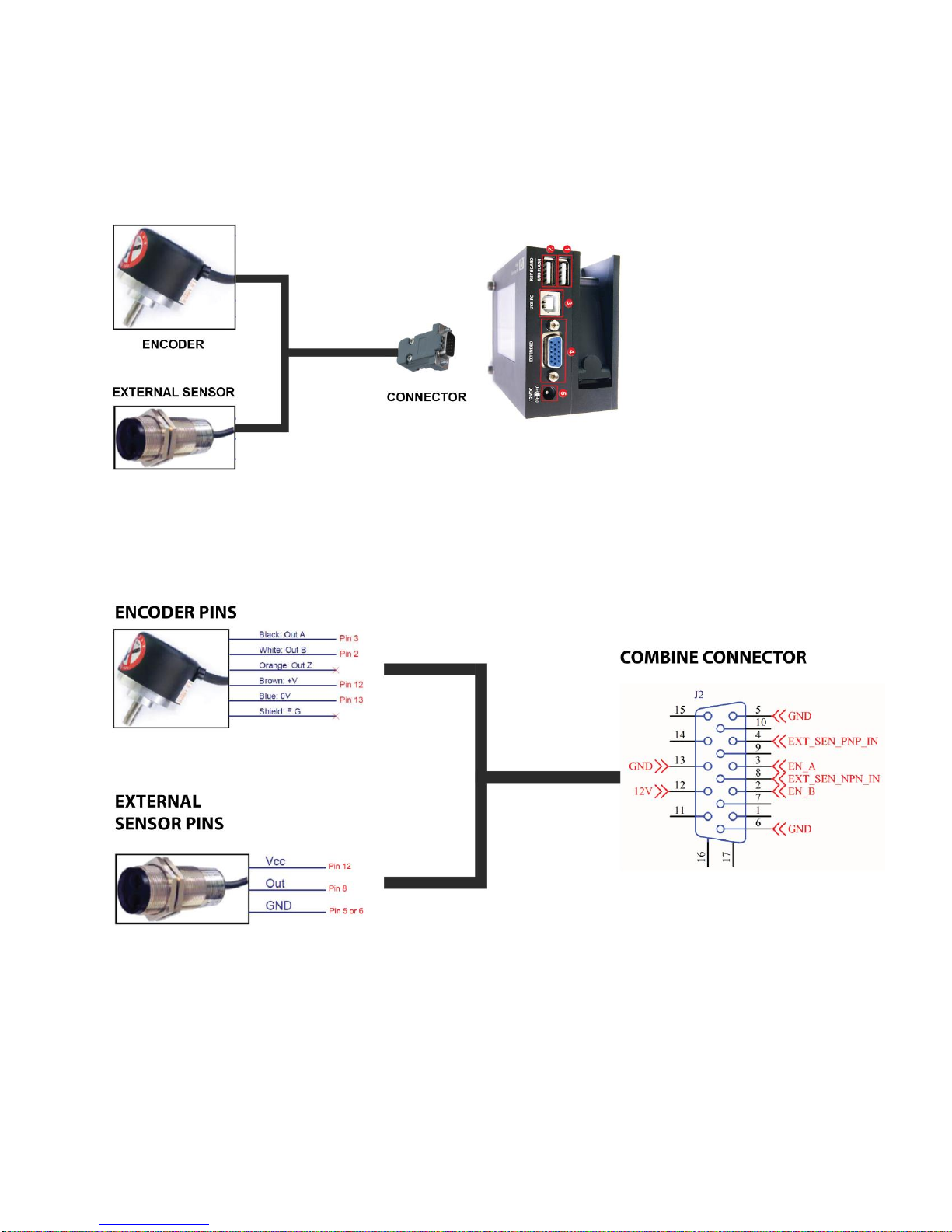
COMBINE EXTERNAL SENSOR AND ENCODER
In some case you need to use external sensor and encoder to get perfect printing quality. But the
machine have one extended port only. Please do as following instruction to take external sensor and
encoder work together with machine.
See picture for this situation.
See this picture for connection pins.
NOTES:
PIN12 (12V) use for both of Encoder and External sensor.
USER MANUAL V02 | Updated 18-Jan-2016 24

ALARM
Allow users to monitor operation of Machine from distance via the light signals from the Alarm.
INPUT AND OUTPUT
Input: To trigger some functions (reset counter …). Accept NPN or dry contact.
Output: NPN signal. Active when some even occur (each print …).
RS485 PROTOCOL
Allow control machine via RS485 network from other devices like: PLC, PC…
Before use this protocol you need to set parameter on machine as below.
Step 1
Connect PIN 1 (RS485B) and PIN 11 (RS485A) to RS485 network as picture below.
Machine extended port detail:
USER MANUAL V02 | Updated 18-Jan-2016 25
 Loading...