


P ER F E CT S OL U TI O N S I N G AS A L AR M S Y ST E MS
www.m s r -e le ctro n i c. de
MSR-Electronic GmbH ::: Würdinger Str. 27 + 27A ::: 94060 Pocking
Specifications subject to change without notice
PolyGard® is a registered trademark of MSR-Electronic GmbH
PolyGard®2 MSC2
Multi Sensor Controller
Datasheet and User Manual
Version 6.2 2015 eng.
Specifications subject to change without notice.

P ER F E CT S OL U TI O N S I N G AS A L AR M S Y ST E MS
www.m s r -e le ctro n i c. de
Page 2 | Dec. 2015
Po l y G a rd ® 2 MSC 2 – Da t a Sh e et a n d Us e r M a n u al
MSR-Electronic GmbH ::: Würdinger Str. 27 + 27A ::: 94060 Pocking
Specifications subject to change without notice
PolyGard® is a registered trademark of MSR-Electronic GmbH
MSC2- Multi Sensor Controller for toxic and combustible
gases, refrigerants and oxygen
Gas measuring, monitoring and warning controller based on state-of-the-art microtechnology for continuous monitoring of the ambient air for toxic and combustible
gases, refrigerants or oxygen.
The MSC2 has an input for connecting a digital sensor cartridge (SC2) that transmits
the temperature-compensated measurement value in digital form. The controller
monitors this value and activates the alarm relay if the set alarm thresholds for prealarm and main alert are exceeded. The main alarm is additionally signalized by the
integrated buzzer and the three-colour status LED, alarm-fault-operation-service. In
case of an internal fault in the sensor cartridge or in the MSC, both equipped with
integrated SIL2 compliant self-monitoring, the fault message relay is triggered. The
remote monitoring is possible via the integrated RS 485 interface with serial
protocol.
For convenient operation the MSC2 is already completely configured and
parameterized ex works.
The intended sites within the ambient conditions as specified in the Technical Data are all areas being directly connected
to the public low voltage supply, e.g. residential, commercial and industrial ranges as well as small enterprises (according
to EN50 082).
The PolyGard® Multi Sensor Controller MSC2 must not be used in potentially explosive atmospheres.
APPLICATION
The MSC2 is designed for leakage detection in refrigeration plants.
FEATURES
Internal function monitoring with integrated hardware watchdog
Hardware and software according to SIL2 compliant development process
Easy maintenance and calibration by replacing the sensor cartridge or via comfortable on-site calibration
Modular technology (plug-in and exchangeable)
Reverse polarity protected, overload and short-circuit proof
For one sensor cartridge (SC) at the housing
Three relays with change-over contact, potential-free max. 250 V AC, 5 A
Two transistor outputs, 24 V DC, 0.1 A (plus switching)
Two digital inputs, one of them is occupied for external reset of the horn
Alarm thresholds alterable via jumper 0.5 / 1.0 vol % or 1.0 / 1.8 vol %
Different types of housing
Status LED for alarm, fault, operation and service
Buzzer
Operating voltage 230 V AC, power supply with wide range input 90 to 240 V AC
Operating voltage 24 V DC (option)

P ER F E CT S OL U TI O N S I N G AS A L AR M S Y ST E MS
www.m s r -e le ctro n i c. de
Page 3 | Dec. 2015
Po l y G a rd ® 2 MSC 2 – Da t a Sh e et a n d Us e r M a n u al
MSR-Electronic GmbH ::: Würdinger Str. 27 + 27A ::: 94060 Pocking
Specifications subject to change without notice
PolyGard® is a registered trademark of MSR-Electronic GmbH
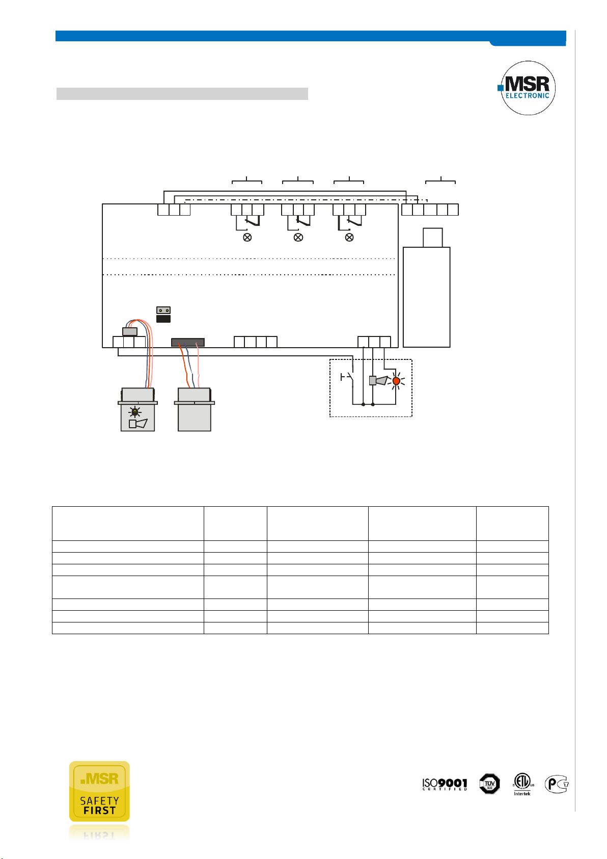
0.5/ 1.0 Vol %
1.0/ 1.8 Vol%
Alarm Threshold
Selectable via Jumper
Power Supply
230 V AC
(1 Vol %)
Relay
Alarm 1
(1.8 Vol %)
Relay
Alarm 2
Relay
Fault
X1 X2 X3 X4
1 112 223 3
1 1 12 2 2 23 3 3 3
LNPE*
Multi Sensor Controller MSC2 -Carrier-
CO2
Sensor
Field Bus Digital
Output
SC2-I1164-B
GND
DI_1
Flashlight
DI_2
GND
Horn
X12
1
X13
BUS_A
BUS_B
X11
Digital
Input
Acknow.
Horn
(1.8 Vol %)
Alarm 2
* Connect to ground, if at 230 V supply, a potential
difference to ground ( floating ground) isn’t allowed.
3 4
AO_01
GND
(Option)
(0 - 5 Vol %)
ORDERING INFORMATION
MSC2- C - 5 3 4 4 2 0 0 0
WARNING DEVICES
0 Without built-on warning device
DISPLAY
0 Without display
ANALOG INPUT
0 Without analog input
DIGITAL INPUT
2 2x Digital input
OUTPUT SIGNAL – ANALOG / BUS
4 Modbus Interface
VISUAL/ AUDIBLE WARNING DEVICES
4 Buzzer & status-LED (red, yellow, green)
ALARM RELAYS
3 3x Alarm relays
POWER SUPPLY
5 90 – 240 V AC / 24 V DC, 5 VA
7 90 – 240 V AC / 24 V DC, 15 VA
HOUSING
C Housing type C 130 x 130 x 75 (mm)
ELECTRICAL CONNECTION 90-240 V AC / 24 V DC 5 VA (qualified technicians only)
P ER F E CT S OL U TI O N S I N G AS A L AR M S Y ST E MS
www.m s r -e le ctro n i c. de
Page 4 | Dec. 2015
Po l y G a rd ® 2 MSC 2 – Da t a Sh e et a n d Us e r M a n u al
MSR-Electronic GmbH ::: Würdinger Str. 27 + 27A ::: 94060 Pocking
Specifications subject to change without notice
PolyGard® is a registered trademark of MSR-Electronic GmbH
Action
Reaction
Relay 1
(Alarm 1)
Reaction
Relay 2, horn &
flashlight (Alarm 2)
Reaction
Relay 3
(collective fault message)
Reaction
LED
Gas signal < alarm threshold 1
OFF
OFF
OFF
GREEN
Gas signal ≥ alarm threshold 1
ON
OFF
OFF
RED
Gas signal ≥ alarm threshold 2
ON
ON
OFF
RED
Gas signal < (alarm threshold 2 Hysterese) aber ≥ alarm threshold 1
ON
OFF
OFF
RED
No alarm, no fault
OFF
OFF
OFF
GREEN
No fault, but maintenance due
OFF
OFF
OFF
GREEN flashing
Internal error
OFF
OFF
ON
YELLOW
0.5/ 1.0 Vol %
1.0/ 1.8 Vol%
Alarm Threshold
Selectable via Jumper
Power
Supply
230 V AC
(1 Vol %)
Relay
Alarm 1
(1.8 Vol %)
Relay
Alarm 2
Relay
Fault
X1 X2 X3 X4
1 112 223 3
1 1 1 PE N L2 2 2 2 V-3 3 3 3 V+
+24 V
GND
Multi Sensor Controller MSC2 -Carrier-
CO2
Sensor
Field Bus Digital
Output
SC2-I1164-B
GND
DI_1
Power Unit
90 to 240 V AC
24 V DC, 15 VA
DI_2
GND
Horn
X12
1
X13
BUS_A
BUS_B
X11
Digital
Input
Acknow.
Horn
(1.8 Vol %)
Alarm 2
(0 - 5 Vol %)
3 4
AO_01
GND
Flashlight
(Option)
* Connect to ground, if at 230 V supply, a potential
difference to tground (floating ground) isn’t allowed.
ELECTRICAL CONNECTION 90-240 V AC / 24 V DC 15 VA (qualified technicians only)
FUNCTION OUTPUTS
Note Relay 1 & 2:
Status OFF means: “Alarm off“ = Relay coil energized
Status ON means: “Alarm on“ = Relay coil de-energized
Note Relay 3:
Note 1: Status OFF = Relay is configured “Alarm ON = Relay“ or the MSC is free from tension.
Status OFF means: “No fault and MSC2 in normal operation“ = Relay coil energized
Status ON means: “ Fault ON or MSC2 without tension“ = Relay coil de-energized
Note 2: Alarm thresholds can have the same value, therefore the relays and/or the horn and flashlight can be triggered
together.

P ER F E CT S OL U TI O N S I N G AS A L AR M S Y ST E MS
www.m s r -e le ctro n i c. de
Page 5 | Dec. 2015
Po l y G a rd ® 2 MSC 2 – Da t a Sh e et a n d Us e r M a n u al
MSR-Electronic GmbH ::: Würdinger Str. 27 + 27A ::: 94060 Pocking
Specifications subject to change without notice
PolyGard® is a registered trademark of MSR-Electronic GmbH
Alarm 2
Relay 2
Gas concentration higher lower than threshold
Acknowledging-
signal
On
Off
On
Off
On
Off
Time Time
Relay Mode
Definition of the relay operation mode. The terms energized / de-energized for this menu item come from the terms
open-circuit and closed-circuit principle used for safety circuits. Here, however, not the relay contact circuit is meant
(because realized as a changeover contact, optionally available in the two principles), but the activation of the relay coil.
The LEDs attached to the modules show the two states in analogy. (LED off -> relay de-energized)
Relay Function Static / Flash
Definition of the relay function: The function "flashing" represents a connection option for warning devices to improve
visibility. If” flashing” is set, this must not be used as a safe output circuit any more.
A combination of relay mode energized with flashing operation makes no sense and is therefore suppressed.
Horn Function (not safe output circuit because resettable)
The horn function is considered active if at least one of the two parameters (time or assignment to digital input) is set.
The horn function retains its functionality even for alarms in latching mode.
Special function Recurrence of the horn relay
After an alarm has been triggered, the horn will remain active until it is acknowledged. After acknowledgment of the horn
relay/s (clicking a button or via external input) a timer starts. When this time has run out and the alarm is still acting, the
relay is set again. This process is repeated endlessly as long as the associated alarm remains active.

P ER F E CT S OL U TI O N S I N G AS A L AR M S Y ST E MS
www.m s r -e le ctro n i c. de
Page 6 | Dec. 2015
Po l y G a rd ® 2 MSC 2 – Da t a Sh e et a n d Us e r M a n u al
MSR-Electronic GmbH ::: Würdinger Str. 27 + 27A ::: 94060 Pocking
Specifications subject to change without notice
PolyGard® is a registered trademark of MSR-Electronic GmbH
XX
XX
MOUNTING / ELECTRICAL CONNECTION
The MSC Gas Controller is fixed to the wall through the four marked mounting points at the back side of the housing.
These mounting points are accessible after opening the housing. See figure.
The dimensions XX depend on the type and can be read on the back of the housing, in the housing version of CX, it is 115
mm.
The mounting points are covered by closing the cover at the end of the assembly.
We recommend considering the following when choosing the mounting position:
Installation height depending on the gas type, for CO2 near the ground approx. 0.3 m above floor.
Cables are introduced from above, the sensor head SC downwards.
Observe possible constructor’s instructions.
Mounting Controller:
Wiring
The technical requirements and regulations for wiring, electrical security, fire protection, as well as project specific and
environmental conditions etc. must be observed when mounting.
We recommend the following cable types 1
Power supply 230 V at least NYM-J 3 x 1.5 mm
Alarm message 230 V (also possible together with power supply) NYM-J X x 1.5 mm
Signal message, bus connection to DGC06, warning devices 24 V J-Y(St)Y 2x2 x 0.8
Possibly connected external analog transmittera J-Y(St)Y 2x2 x 0.8
1
The recommendation does not consider local conditions such as fire protection etc.
2
2
Analog sensors are connected directly to the spring type terminals of the module. The correct polarity must be observed.
Digital gas sensors are directly plugged in the connector.
The alarm signals are available as potential-free change-over contacts. If required the voltage supply is available at the
terminals L1.
The exact position of the terminals for the sensors and alarm relays is shown in the connection diagram.

P ER F E CT S OL U TI O N S I N G AS A L AR M S Y ST E MS
www.m s r -e le ctro n i c. de
Page 7 | Dec. 2015
Po l y G a rd ® 2 MSC 2 – Da t a Sh e et a n d Us e r M a n u al
MSR-Electronic GmbH ::: Würdinger Str. 27 + 27A ::: 94060 Pocking
Specifications subject to change without notice
PolyGard® is a registered trademark of MSR-Electronic GmbH
COMMISSIONING
For sensors that e.g. can be poisoned by silicones like all semiconductor and catalytic bead sensors, it is imperative to
remove the protective cap supplied only after all silicones are dry, and then energize the device.
The protective cap has to be used in subsequent cleaning work with water jet or steam, too, in order to protect the
sensor.
For fast and comfortable commissioning we recommend proceeding as follows. For digital devices with self-monitoring
all internal errors are visible via the LED. All other error sources often have their origins in the field, because it is here
where most of the causes for problems in the field bus communication appear.
Optical Check
Right cable type used.
Correct mounting height according to definition in Mounting.
Led status
Protective cap removed from the sensor.
Run-in period
In order to obtain an optimum fresh air setting, it is necessary to run the unit continuously at least for 48 hours without
shutdown under unpolluted ambient air conditions.
Selection Gas Type with Unit
The selection of the desired and connected gas sensor type is made by pre-set values.
If other gas sensor types are connected, you have to adjust them with the configuration tool, because otherwise the
device will respond with an error message.
Connection possible as digital sensor cartridge SC2.
The selection contains all necessary information for the controller and is also used for comparing the real, digital data
with the settings.
This feature increases the user and operating security.
There is an entry available per gas type for each unit; at the moment there are 100 selection options.

P ER F E CT S OL U TI O N S I N G AS A L AR M S Y ST E MS
www.m s r -e le ctro n i c. de
Page 8 | Dec. 2015
Po l y G a rd ® 2 MSC 2 – Da t a Sh e et a n d Us e r M a n u al
MSR-Electronic GmbH ::: Würdinger Str. 27 + 27A ::: 94060 Pocking
Specifications subject to change without notice
PolyGard® is a registered trademark of MSR-Electronic GmbH
MSR-Type
Gas Type
Formula
Range
unit
1164
Carbon dioxide
CO2
0-2000
ppm
1164
Carbon dioxide
CO2
0-5
% Vol
3480
Propane
C3H8
0-100
% LEL
I480
IR-Propane
C3H8
0-100
% LEL
I480
IR-Propane
C3H8
0-100
% Vol
2066
R11
R11 ppm
2059
R12
R12
20-2000
ppm
2070
R22
R22
20-300
ppm
2061
R23
R23
20-2000
ppm
2060
R32
R32 ppm
2064
R123
R123
20-300
ppm
2077
R134a
R134a
20-300
ppm
2063
R1234yf
R1234yf
ppm
2065
R125
R125 ppm
2071
R401a
R401a
20-2000
ppm
2072
R401b
R401b
20-2000
ppm
2073
R402a
R402a
20-2000
ppm
2074
R402b
R402b
20-2000
ppm
2082
R403a
R403a
ppm
2078
R404a
R404a
20-300
ppm
2083
R407a
R407a
ppm
2080
R407c
R407c
20-300
ppm
2075
R408a
R408a
20-2000
ppm
2076
R409a
R409a
20-2000
ppm
2068
R410a
R410a
20-300
ppm
2067
R411a
R411a
20-300
ppm
2079
R416a
R416a
20-300
ppm
2084
R417a
R417a
20-2000
ppm
2081
R422d
R422d
20-300
ppm
2062
R434a
R434a
20-300
ppm
2069
R507
R507
20-2000
ppm

P ER F E CT S OL U TI O N S I N G AS A L AR M S Y ST E MS
www.m s r -e le ctro n i c. de
Page 9 | Dec. 2015
Po l y G a rd ® 2 MSC 2 – Da t a Sh e et a n d Us e r M a n u al
MSR-Electronic GmbH ::: Würdinger Str. 27 + 27A ::: 94060 Pocking
Specifications subject to change without notice
PolyGard® is a registered trademark of MSR-Electronic GmbH
Commission:
Order number:
Customer:
Service technician:
Commissioning - company:
Date
Serial
No.
Date of
Production
Mainten.
interval
Mainten.
Password
AV Overlay
AV Time
Power On
Time
Error
Time
CFM
dupl.
Note
Note down
1900
****
V-time
ppm 0 0 0
90
30
30
Analog Output 1
Outp.
source
Oper.
Signal Mode
100%
CV
MAX
Relay Multiplication
1 2 3 4 5
In
Out
In
Out
In
Out
In
Out
In
Out
0 0 0 0 0 0 0 0 0 0
R 01
active
energ.
R 02
active
energ.
R 03
active
de-en
Horn
active
de-en
LED red
active
de-en
flash 1
Relay
No.
active
inactive
Mode
Stat.
Flash
Reset
Horn
Extern.
On
Extern.
Off
Delay
at ON
Delay
at OFF
Fault
ORed
Maint.
ORed
Time
Recur.
DI
DI
DI
sec
sec
Default
inactive
de-en
Stat. 0 no 0 0 0 0 0 OFF
OFF
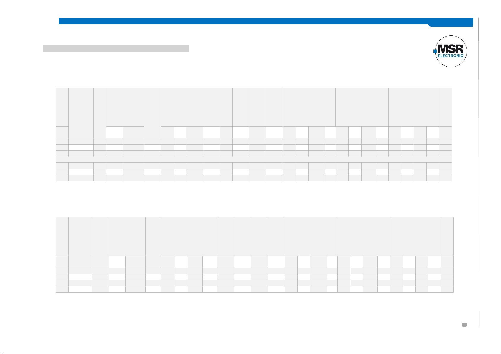
CONFIGURATION AND PARAMETER CARDS
Configuration Card System Parameters
Configuration Card Alarm Relays / Signal Outputs
P ER F E CT S OL U TI O N S I N G AS A L AR M S Y ST E M S
www. ms r-e l e ct ro ni c.d e
MSR-Electronic GmbH ::: Würdinger Str. 27 + 27A ::: 94060 Pocking
Po l y G a rd ® 2 MSC 2 – Da t a Sh e et a n d Us e r M a n u al
DP Nr.
MP
Status
Locked
Gas type
Range
Alarm
Thresholds
Hyst
CV- Delay Alarm
(Sec)
CV-AV
Assignment
Latching
Assignment
Fault
<>Alarm
Assignment
Alarm
<> Alarm Relay
Ao1
Gas
unit
A1
A2
A3
A4 at
ON
at
OFF
A1
A2
A3
A4 A1
A2
A3
A4
A1
A2
A3
A4
01
active
n
CO2
%Vol
5
0.5 1 1 1 0.2 0 0
CV 0 0 0 0 1
R1
R2
R3
R4
02
inactive
n
03
inactive
n
Change of values after replugging the jumper (closed)
01
active
n
CO2
%Vol 5 1
1.8 1 1
0.2 0 0
IW 0 0 0 0 1
R1
R2
R3
R4
02
inactive
n
03
inactive
n
AP Nr.
MP
Status
Locked
Gas type
Range
Alarm
Thresholds
Hyst
AV- Delay Alarm
(Sec)
CV-AV
Assignment
Latching
Assignment
Fault
<>Alarm
Assignment
Alarm
<> Alarm Relay
Ao1
Gas
unit
A1
A2
A3
A4 at
ON
at
OFF
A1
A2
A3
A4 A1
A2
A3
A4
A1
A2
A3
A4
inactive
No
CO2
ppm
300
30
60
120
120
15 0 0
AV 0 0 0 0 1
R1
R2
R3
R4 01
inactive
02
inactive
03
inactive
Configuration Card SC2 devices (digital measuring points)
Configuration Card MC2 (analog measuring points)

MSR-Electronic GmbH ::: Würdinger Str. 27 + 27A ::: 94060 Pocking
P ER F E CT S OL U TI O N S I N G AS A L AR M S Y ST E MS
www. ms r-e l e ct ro ni c.d e
Page 11 | Dec. 2015
Po l y G a rd ® 2 MSC 2 – Da t a Sh e et a n d Us e r M a n u al
Specifications subject to change without notice
PolyGard® is a registered trademark of MSR-Electronic GmbH
FUNCTIONAL TEST (FOR INITIAL OPERATION AND MAINTENANCE)
The functional test should be carried out during each service, but at least once a year.
ZERO-POINT TEST WITH FRESH OUTDOOR AIR
Due to the employed optical measurement principle, there won’t be any deterioration caused by ageing or chemical
processes in the sensor. However, a zero offset may occur.
Using the Service Tool STL 06 you can read it out and document it in form of a measured value.
TRIP TEST WITH REFERENCE GAS
The sensor is gassed with reference gas CO2, concentration, 2-3 % vol, (for this you need a gas bottle with pressure
regulator and a calibration adapter).
In doing so, the set alarm thresholds are exceeded, and all output functions are activated. It is necessary to check if the
connected output functions are working correctly (e.g. the horn sounds, the fan switches on, devices shut down). By
pressing the push-button on the horn, the horn acknowledgment must be checked. After removal of the reference gas,
all outputs must automatically return to its initial position.
Other than the simple functional testing, it is also possible to perform a functional test by means of calibration. For
further information, please refer to the User Manual.
CALIBRATION
New Sensor Cartridges SC2 are always delivered factory-calibrated by MSR-E. This is documented by the calibration label
indicating date and calibration gas. A repeated calibration is not necessary during commissioning if the device is still in its
original packaging (air-tight protection by the red protective cap) and the calibration doesn’t date back more than 12
months for CO2 sensors and 3 months for all other gases.
Due to high operational stability of the sensor, and the intrinsically safe design of the gas detector, the gas detector
doesn’t need an annual calibration.
After an operating period of 5 years, only the sensor cartridge must be recalibrated & adjusted by the manufacturer or
replaced. If this time has been exceeded, the device answers automatically with the green LED flashing. This replacement
of the sensor cartridge can be repeated without limitation, as long as there isn’t a malfunction (fault X4). The evaluation
unit must not be exchanged.
After exchange of the sensor, the LED shows the correct operation again (green).
MSR-Electronic GmbH ::: Würdinger Str. 27 + 27A ::: 94060 Pocking
P ER F E CT S OL U TI O N S I N G AS A L AR M S Y ST E MS
www. ms r-e l e ct ro ni c.d e
Page 12 | Dec. 2015
Po l y G a rd ® 2 MSC 2 – Da t a Sh e et a n d Us e r M a n u al
Specifications subject to change without notice
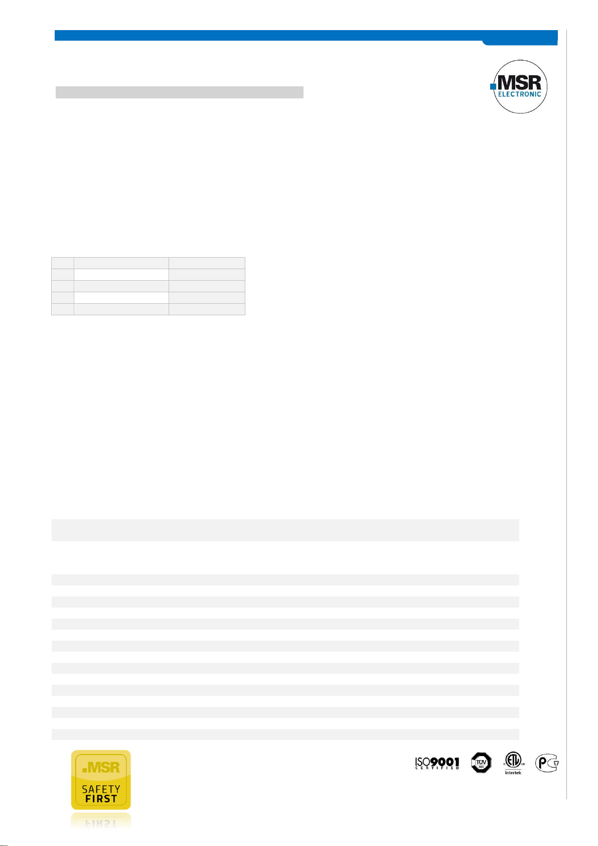
PolyGard® is a registered trademark of MSR-Electronic GmbH
Sensor/Gas type
Ton
01
CO2
2 days fresh air
02
Combustible gases
1 h
05
NH3
18 h
07
Freons
8 days
Electrical
Power supply
90 - 240 V AC,
24 V DC reverse-polarity protected (option)
Power consumption (24 V DC)
- per sensor (SC or MC)
- horn / warning light
Max. 60 mA (1.5 VA)
Max. 85 mA (2.1 VA)
Max. 40 mA (1.0 VA)
Alarm relays (3)
250 V AC, 5 A, potential-free, change-over contact (SPDT)
Transistor outputs (2)
24 V DC / 0.1 A, (switching to plus)
Digital inputs (2)
Potential-free contact
Ambient conditions
Temperature range
-25 °C to +50 °C (-13 °F to +122 °F)
Humidity range
15 - 95 % RH not-condensing
Storage temperature
5 °C to 30 °C (41 °F to 86 °F)
Storage time
12 months in original packaging
Physical
Housing type C
Polycarbonate
Combustion
UL 94 V2
Housing colour
RAL 7032 (light grey)
Dimension housing (W x H x D)
130 x 130 x 75 mm (5.12 x 5.12 x 2.95 in.)
Weight
ca. 0.6 kg (1.32 lb.)
Protection class
IP 65
For the calibration of the sensor cartridge, you need a PC tool or the MSC-06-STL Service Tool. There is an automatic
routine in the calibration menu of the Service Tool STL.
As long as the calibration menu is open and the sensor is gassed with test gas, the alarm release is blocked.
Prior to calibration the sensor must be connected continuously to the power supply for stabilization for a running-in
period.
This running-in period of some sensors can be taken from the following table:
Project protection
To prevent access to the sensitive calibration data by third parties, every customer receives his own internal project key.
All projects of the customer are delivered with this key. The key is also stored in each MSC-06-STL Tool that the
respective customer buys.
If the keys do not match, the following message appears
NO ACCESS AUTHORIZATION
The calibration is documented in the User Manual of the Service Tool.
SPECIFICATIONS MULTI SENSOR CONTROLLER
MSR-Electronic GmbH ::: Würdinger Str. 27 + 27A ::: 94060 Pocking
P ER F E CT S OL U TI O N S I N G AS A L AR M S Y ST E MS
www. ms r-e l e ct ro ni c.d e
Page 13 | Dec. 2015
Po l y G a rd ® 2 MSC 2 – Da t a Sh e et a n d Us e r M a n u al
Specifications subject to change without notice
PolyGard® is a registered trademark of MSR-Electronic GmbH
Installation
Wall mounting
Cable entry
Standard 3 x M20/25
Wire connection: Local bus (SC)
Digital input, analog output
Power supply, relays
3-pin connector
Screw-type terminals, min. 0.25 mm2, max. 1.3 mm
2
Screw-type terminals, min. 0.25 mm2, max. 2.5 mm
2
Warning buzzer
Acoustic pressure
> 90 dB (A)
Frequency
2300 Hz
Protection class
IP 65
Status-LED
Colour / mode
Red / yellow / green (warning-fault-operation-service)
Protection class
IP 65
Scope included
3x M20x1.5
Cable gland for MSC2
1x M16x1.5
Cable gland for WH/BL24-Tast
Sensor element
Gas type
Carbon dioxide CO2
Sensor element
Infrared (NDIR)
Measuring range
5 vol. %
Measuring interval
2 sec.
Accuracy
< 10 % of range
Response time
t90 < 120 s
Sensor life time
15 years for normal ambient conditions
Calibration interval (recommendation)
5 years
Temperature range
-35 to + 40 °C
Humidity range
0 - 90 % RH not condensing
Pressure range
Atmospheric ± 30 % (influence + 1.6 % on measured value per kPa)
Storage temperature range
+ 5 to + 30 °C (41 to 86 °F)
Storage time
12 months in their original packaging
Physical
Housing M25
Polycarbonate
Combustion
UL 94 V2
Housing colour
RAL 7032 (light grey)
Dimensions: M25 housing
(D x H) 24 x 22 mm (0.94 x 0.87 in.)
Weight
ca. 30 g (0.07 lb)
Protection class
IP 65
Mounting
Screw mounting
Connection type
3-pin connector
Cable length
110 mm (4.33 in.)
Directives
EMC directives 2004/108/EC
CE
Conformity to:
EN 50271
EN 61010-1:2010
ANSI/UL 61010-1
CAN/CSA-C22.2 No. 61010-1E
EN 378-1 (refrigeration plants)
Warranty
1 year on material
SPECIFICATIONS SENSOR CARTRIDGE

MSR-Electronic GmbH ::: Würdinger Str. 27 + 27A ::: 94060 Pocking
P ER F E CT S OL U TI O N S I N G AS A L AR M S Y ST E MS
www. ms r-e l e ct ro ni c.d e
Page 14 | Dec. 2015
Po l y G a rd ® 2 MSC 2 – Da t a Sh e et a n d Us e r M a n u al
Specifications subject to change without notice
PolyGard® is a registered trademark of MSR-Electronic GmbH
NOTES AND GENERAL INFORMATION
It is important to read this user manual carefully in order to understand the information and instructions. The PolyGard®2
MSC system may only be used for applications in accordance to the intended use. The appropriate operating and
maintenance instructions and recommendations must be followed.
Due to permanent product developments, MSR-E reserves the right to change specifications without notice. The
information contained herein is based on data considered to be accurate. However, no guarantee or warranty is
expressed or implied concerning the accuracy of these data.
Intended Product Application
The PolyGard®2 MSC system is designed and manufactured for controlling, for saving energy and keeping OSHA air
quality in commercial buildings and manufacturing plants.
Installer’s Responsibilities
It is the installer’s responsibility to ensure that all PolyGard®2 MSC systems are installed in compliance with all national
and local regulations and OSHA requirements. All installation shall be executed only by technicians familiar with proper
installation techniques and with codes, standards and proper safety procedures for control installations and the latest
edition of the National Electrical Code (ANSI/NFPA70).
The equipotential bonding required (also e.g. secondary potential to earth) or grounding measures must be carried out in
accordance with the respective project requirements. It is important to ensure that no ground loops are formed to avoid
unwanted interference in the electronic measuring equipment.
It is also essential to follow strictly all instructions as provided in the user manual.
Maintenance
We recommend checking the PolyGard®2 MSC system regularly. Due to regular maintenance differences in efficiency can
easily be corrected. Re-calibration and replacement of parts can be realised on site by a qualified technician with the
appropriate tools. A separate documentation is available for this. Alternatively the removable Gas Controller can be
returned to MSR-Electronic GmbH for services.
Limited Warranty
MSR-Electronic GmbH warrants the PolyGard®2 MGC system against defects in material or workmanship for a period of
one (1) year beginning from the date of shipment. Should any evidence of defects in material or workmanship occur
during the warranty period, MSR will repair or replace the product at their own discretion, without charge. This warranty
does not apply to units that have been altered, had attempted repair, or been subjected to abuse, accidental or
otherwise. The above warranty is in lieu of all other explicit warranties, obligations or liabilities.
This warranty extends only to the PolyGard®2 MSC system. MSR-Electronic GmbH shall not be liable for any incidental or
consequential damages arising out of or related to the use of the PolyGard®2 MSC systems.

MSR-Electronic GmbH ::: Würdinger Str. 27 + 27A ::: 94060 Pocking
Specifications subject to change without notice
PolyGard® is a registered trademark of MSR-Electronic GmbH
 Loading...