

Page 1
Preliminary
Page 2

Information
Technical And Operational Description
Card Data Format
Connections
Demo Software
Contents
.........................................................................................
1
3
6
8
9
..........................................
.................. ..... ..... ..... .... ..... ..... ..... ................... .....
.........................................................................................
.................................................................................
FCC COMPLIANCE STATEMENT
This equipment has been tested and found to comply with the limits for a
Class A digital device, pursuant to Part 15 of the FCC Rules. These limits are
designed to provide reasonable protection against harmful interference when
the equipment is operated in a commercial environment. This equipment
generates, uses, and can radiate radio frequency energy and, if not installed
and used in accordance with the instruction manual, may cause harmful
interferen ce to radi o com munication.
Operation of this equipment in a residential area is likely to cause harmful
interference in which case the user will be required to correct the interference
at his own expense.
15
.....................................................................................
Specifications
16
...................................................................
Communic at ion Pr otocol
USB Driver Setup
.................. ..... ..... ..... ..... ..... .... ..... .................... .... ...
23
Page 3
Information
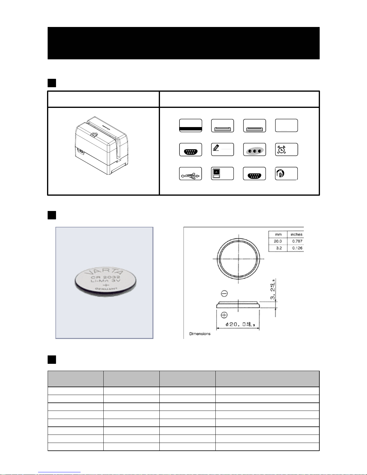
Mini123 Series Magnetic Sw ipe Reader
Mini123
Track 1 & 2 & 3
MACHINE TYPE FUNCTION
- 1 -
G
ET
VER 1.2
N
F-MEM
512 KB
1 2 3
MC
BEEP
OFF
AUTO
OFF
BATTERY
2032
LOW BAT
2032
RTC
2048
REC QUEUE
Lithium Coin For Mini123 R e ader
GPCR2032 GP BATTEIES 210mAh http://www.gpbatteries.com.hk
ECR2032 EVEREADY 225mAh http://www.eveready.com
CR2032 VARTA 230mAh http://www.varta.com
DL2032 DURACELL 220mAh http://www.duracell.com
FDK 220mAh http://www.fdk.co.jp
CR2032 PANASONIC 220mAh http://www.panasonic.co.jp
CR2032
CR2032 MAXELL 210mAh http://www.maxell.co.jp
CR2032 Renata 235mAh http://www.renata.com
Model
Nominal
capacity (mAh)
Brand Web Site
POWER
LED STATUS
RS-232
Replacement battery information
USB
Ver 1.1
Page 4
Information
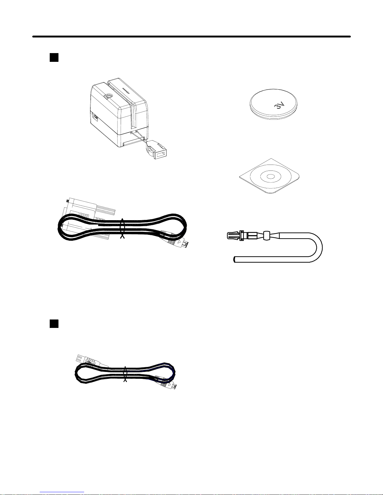
Standard Package
Main unit
( Mini123 )
- 2 -
RS232 Cable
( WAS-1543 )
Battery 3V
( BAT-T0004 )
CD-ROM
( DISK5196 )
Chain Sling
Option
USB Cable
( WAS-1571 )
Page 5
Front Panel Di sp la y and Oper a tion s
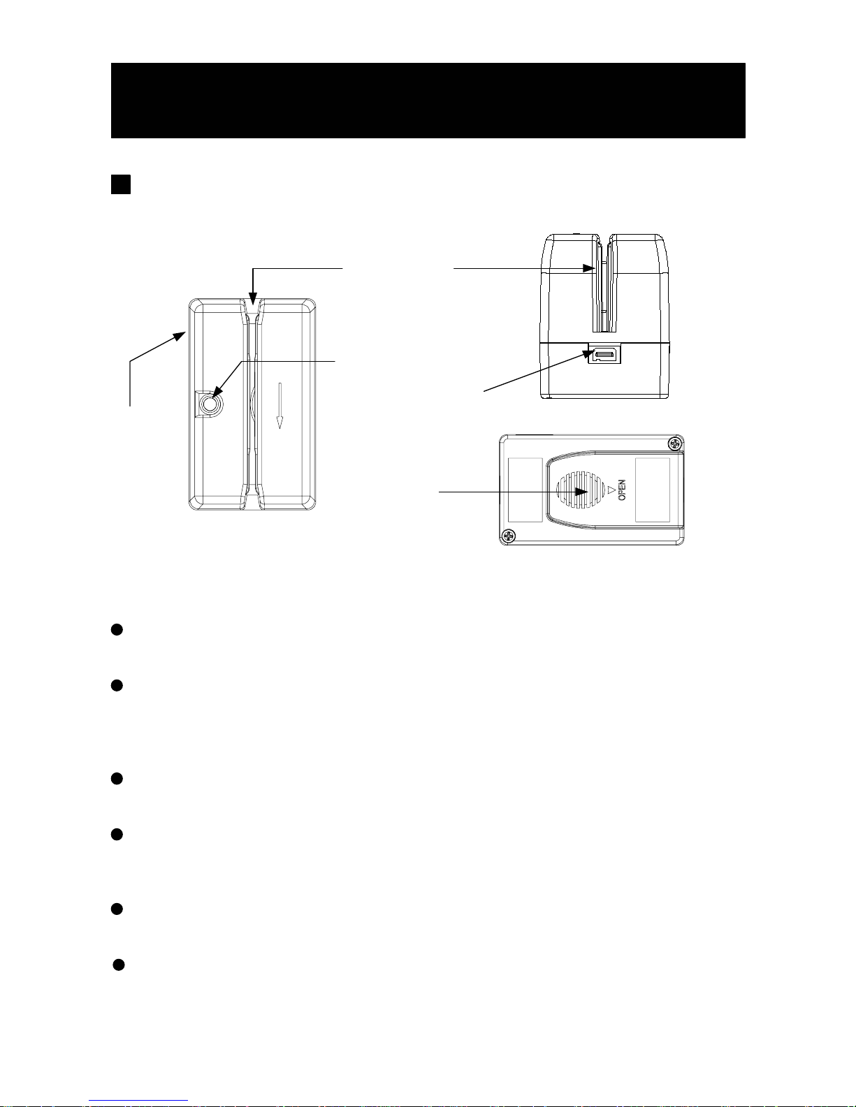
CARD
READER
STATUS
INDICATOR
STATUS INDICATOR ( Green color )
Indicating the reader is ready to accept new inputs or memory full.
STATUS INDICATOR ( Red color )
When encounter ing erroneous input, def ective card, misrea d, lo w batt ery
,bad memory or incorrectly encoded data and so on, the device will turn
on the ERROR indicat or .
CARD READER
Swipe the card thro ug h the entire length of the slot to rea d .
Technical And Operational Description
- 3 -
BATTERY
BOX
CONNECTOR
BATTERY BOX
Put the battery in box and hold battery .
CONNECTOR
For connection to host computer and external Power from the host
computer .
POWER
BUTTON
POWER BUTTON
Turn the Mini123 on/off power. Keep pushing for about 0.5 seconds to
turn ON/OFF power.
Page 6
Technical And Operational Description
- 4 -
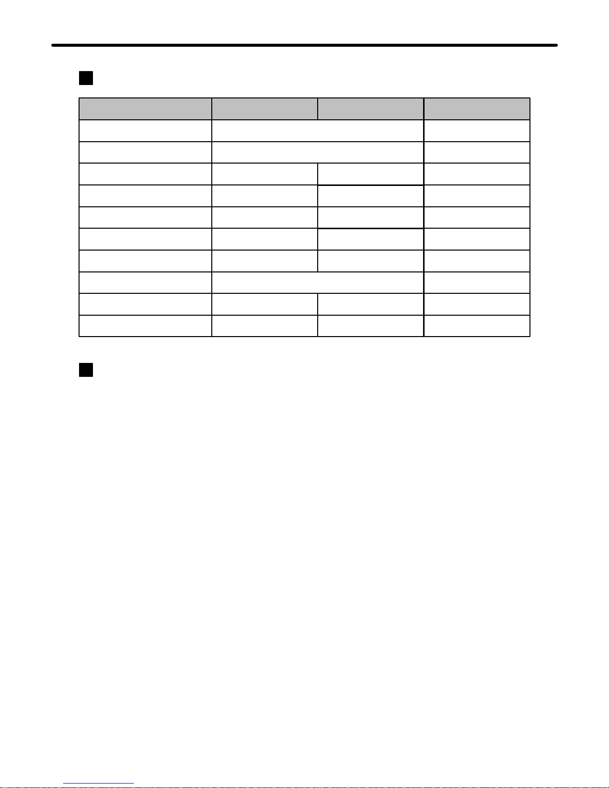
Display Info rmation
Operational Description
1. Powered by Battery
For normal use, the unit is powered by battery. Push the Power Switch Button
for about 0.5 seconds to turn on the unit. Also push the Power Switch Button for about 1
seconds to turn off the unit. After the unit is turned on, the power would be tu rned off
automatically if there is no swiping a card on the unit in 15 seconds (Initial value). This means
the unit would be turned off if no swiping a card again in every 15 seconds (Initial value) after
every card swiping. It would have Low Battery Detect/Warning indication when the unit is
powered by battery.
2. Powered by Cable ( Pls refer to the remarks Connect to PC in page 8. )
3. Real Time Clock Setting
4. Low Battery Dectect
When the unit is connected with the PC through the communication Cable (WAS-1543) and the
PC is running MINI123 software and open the COM PORT for the unit, then the unit will be
turned on in about 0.5 second by the PC through the RS-232 COM PORT. Then you can do the
unit Setting, Configuration or data downloading. When the software closes the COM PORT or
exits, the power turn off from the PC immediately. When powered by cable from PC, the Power
Switch would ha ve no function and the unit w ould have no Low Battery Detect/ Wa rning
function.
Before start using the unit, you must set the Real Time Clock (RTC) inside the unit to your local
time. If there is no battery for quite a while or it is powered by cable for quite a while, this
would cause Real Time clock (RTC) malfunctioned due to no power supply. When put on the
battery to turn on the unit and the Red/Green LE D ta ke turns blinking, this means the RTC is
malfunctioning and y ou must do the RTC time setting b efore you use the unit.
Status
Power On
Ready
Read OK
Read Error
Memory Full
Memory bad
Low Battery
Green LED
Take turns blink 2 times
On
Blink 1 times
Off
Blink
Off
On
Red LED
Off
Off
Blin k 1 times
Off
On
Blin k
Read Card
X
O
X
X
X
X
O
Inactive Battery Off X
RTC No Setting Take t u rns blin k O
Auto Power Off X Take turns blink 2 times
Blin k 3 ti mes
When powered by battery, it would have Low Battery Detect function. When the battery goes
low, the LED would flash red once every 0.5 second during green light and you must change
new battery immediately, otherwise, the unit would shut down any time without pre-warning.
When the battery goes too low to keep the unit working, the LED would flash red three times
and then shut down immediately.
Page 7
Technical And Operational Description
- 5 -
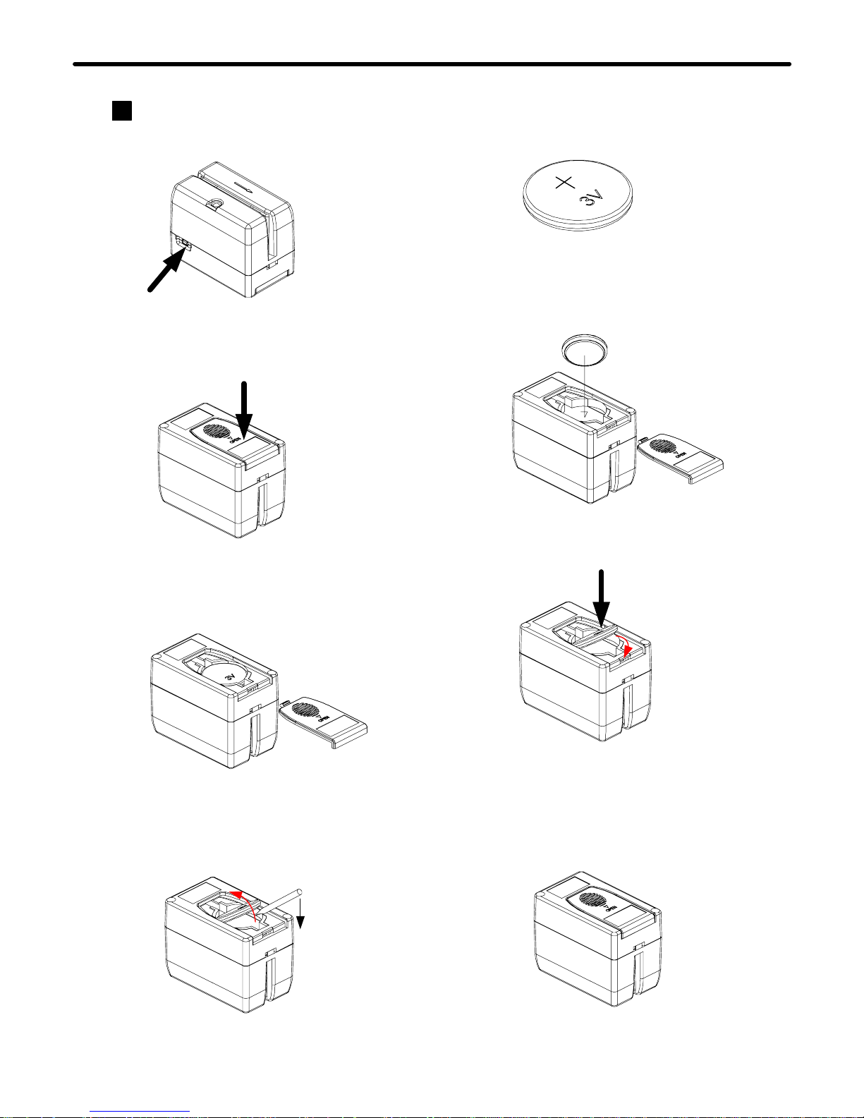
Replace Battery
1. Turn off power
5. Take new battery
3. Pull the cover away
2. Press the cover down
to take off the battery
cover
6. Put new battery in
7. Press the battery down
firmly
Note Positive electrode
direction
8. Put the cover back in
place
4. Use a small screw
driver to take battery
away
Page 8
Connections
- 6 -
PC
RS-232
PORT
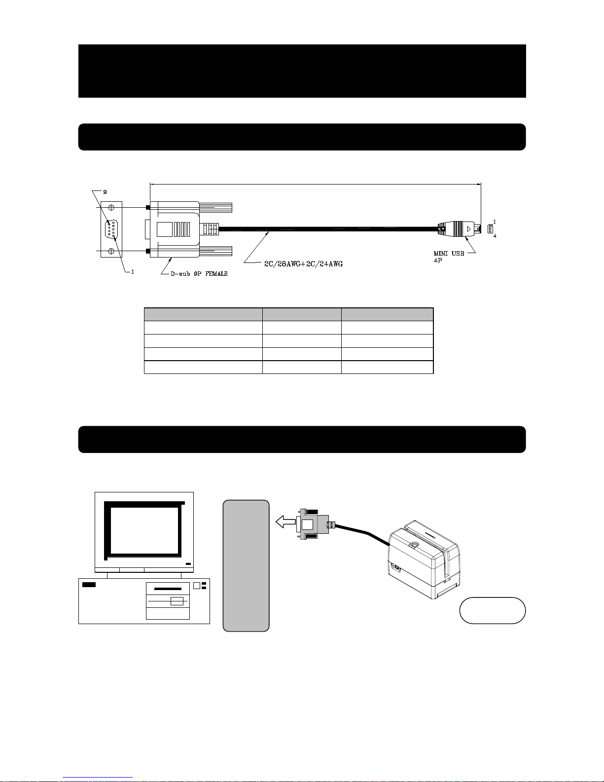
Connect to PC
External
Power
WAS-1543
* DSB 9P FEMALE Pin 4 for power supply
DTR
TXD
RXD
FUNCTION
GND
MINI USB 4P
4
3
2
1
DSB 9P FEMALE PIN
3
2
4*
5
Powered form PC COM port
Note:
When you use the application software to save the data, all records stored in Mini123 will be deleted automatically after saving. For
this procedure consumes much power, Mini123 will reset itself if the PC COM Port does not provide enough power supply. Therefore,
it is recommended to install the battery in Mini123 before saving. The terminal will automatically connect to the battery power to
replenish the power supply when saving the data, and will spontaneously disconnect to the battery after the saving is done. The
battery power is consumed only at the moment of saving the data. Other operations won't consume any battery power at all.
1500+-30
Page 9
- 7 -
PC
USB
PORT
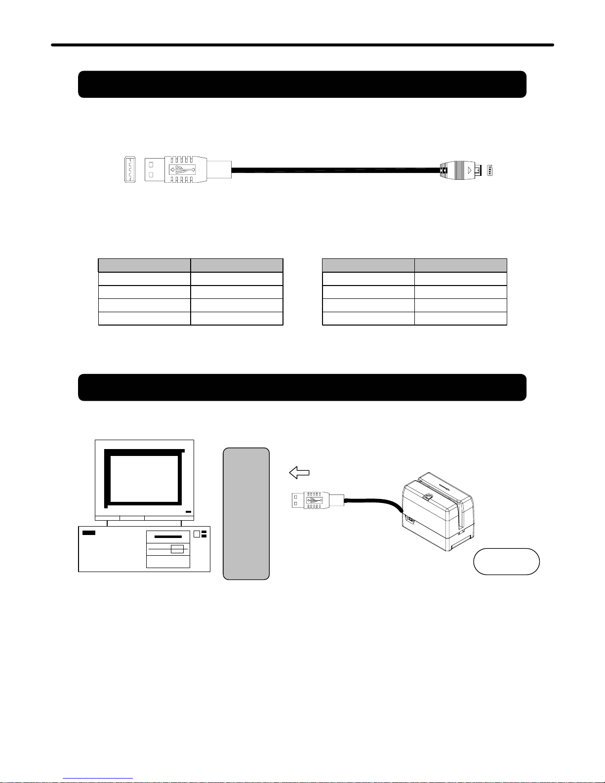
Connect to PC
External
Power
WAS-1571
USB 4P FEMALE PIN
Powered form PC COM port
Note:
When you use the application software to save the data, all records stored in Mini123 will be deleted automatically after saving. For
this procedure consumes much power, Mini123 will reset itself if the PC COM Port does not provide enough power supply. Therefore,
it is recommended to install the battery in Mini123 before saving. The terminal will automatically connect to the battery power to
replenish the power supply when saving the data, and will spontaneously disconnect to the battery after the saving is done. The
battery power is consumed only at the moment of saving the data. Other operations won't consume any battery power at all.
1
3
2
4
1
1
FUNCTION
VCC
D -
D +
GND
MINI USB 4P
1
3
2
4
FUNCTION
RXD
TXD
DTR
GND
Connections
Page 10
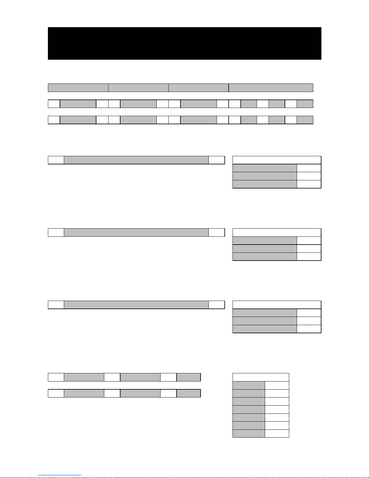
Card Data Format
TRACK1 DATA
CARD DATA STRING
TRACK 1
SS ES
1. SS is the start sentinel ( % ).
2. ES is the end sentinel ( ? ).
3. Card Id up to 76 alphanumeric data characters.
- 8 -
CARD ID% ?
SS ESTRACK2 DATA SS ESTRACK3 DATA
TRACK1 DATA% ? ; ?TRACK2 DATA + ?TRACK3 DATA
TRACK 1 TRACK 2 TRACK 3
Bits Per Inch 210
Bits Per Character 7
Track 1 I ATA
Alphanumeric Characters 79
TRACK 2
1. SS is the start sentinel ( ; ).
2. ES is the end sentinel ( ? ).
3. Card Id up to 37 numeric data characters.
CARD ID; ?
Bits Per Inch 75
Bits Per Character 5
Track 2 ABA
Numeric Characters 40
TRACK 3
1. SS is the start sentinel ( + ).
2. ES is the end sentinel ( ? ).
3. Card Id up to 104 numeric data characters.
CARD ID+ ?
Bits Per Inch 210
Bits Per Character 5
Track 3 Thrift
Numeric Characters 107
DATE & TIME
SP DATE SP TIME SP WEEK
DATE TIME WEEK
SP DATE
DATE&TIME&WEEK
SP TIME WEEKSP
1. SP is the SPACE characters ( 20h ).
2. TIME is 24hr .
YYYY/MM/DD
SP
HH:MM:SS
WSP
WEEK
SUN
MON
TUE
WED
THU
FRI
SAT
1
2
3
4
5
6
7
Note: Track 3 can read both ISO TK3 format and ISO TK1 format .
Page 11
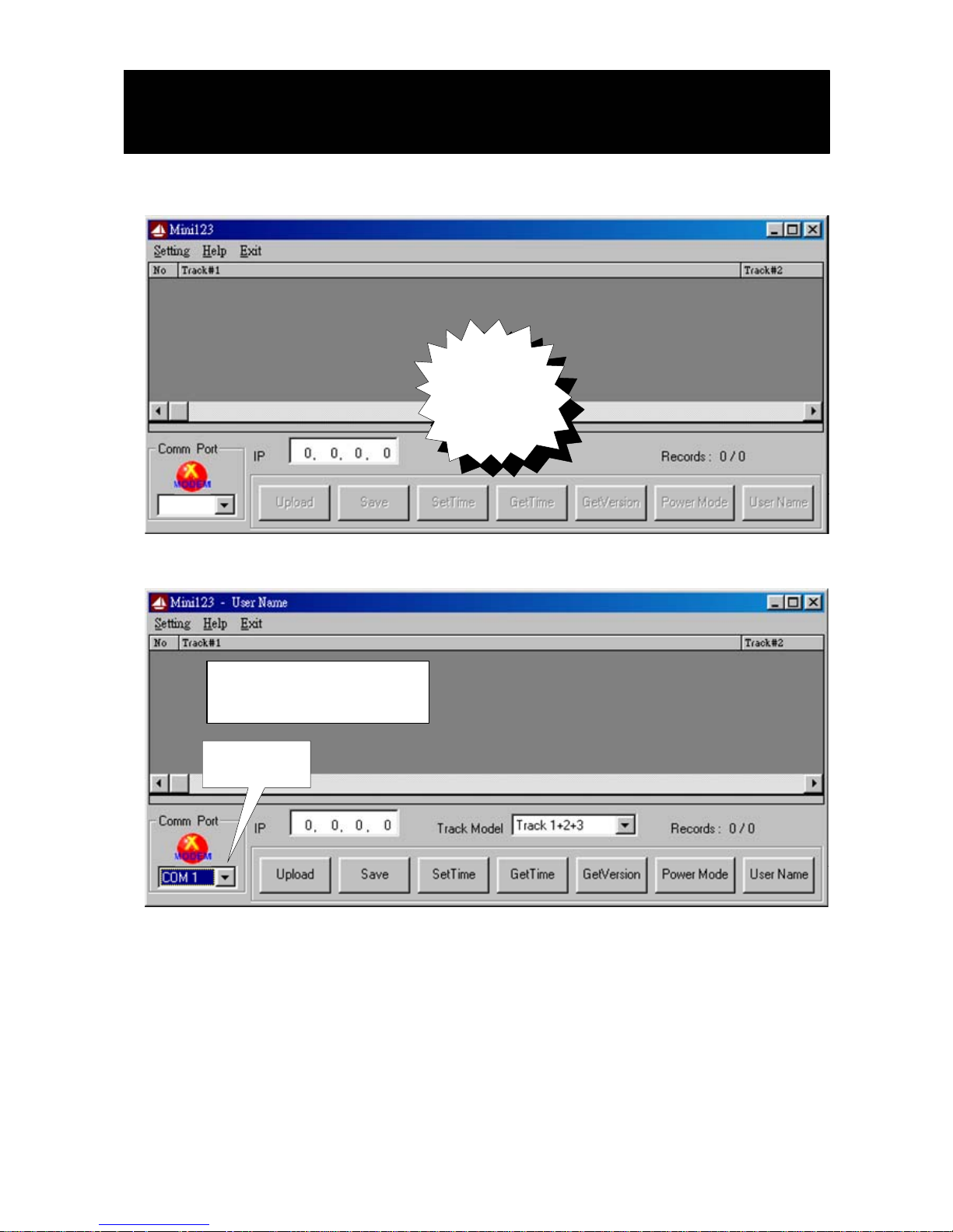
- 9 -
STEP 1 : RUN Mini123
STEP 2 : CHOOSE COM PORT (Do not choose TCP/IP)
START
Mini123
SOFTWARE
Demo Software
CHOOSE
COM PORT
* BAUDRATE : 9 600 BPS
Page 12
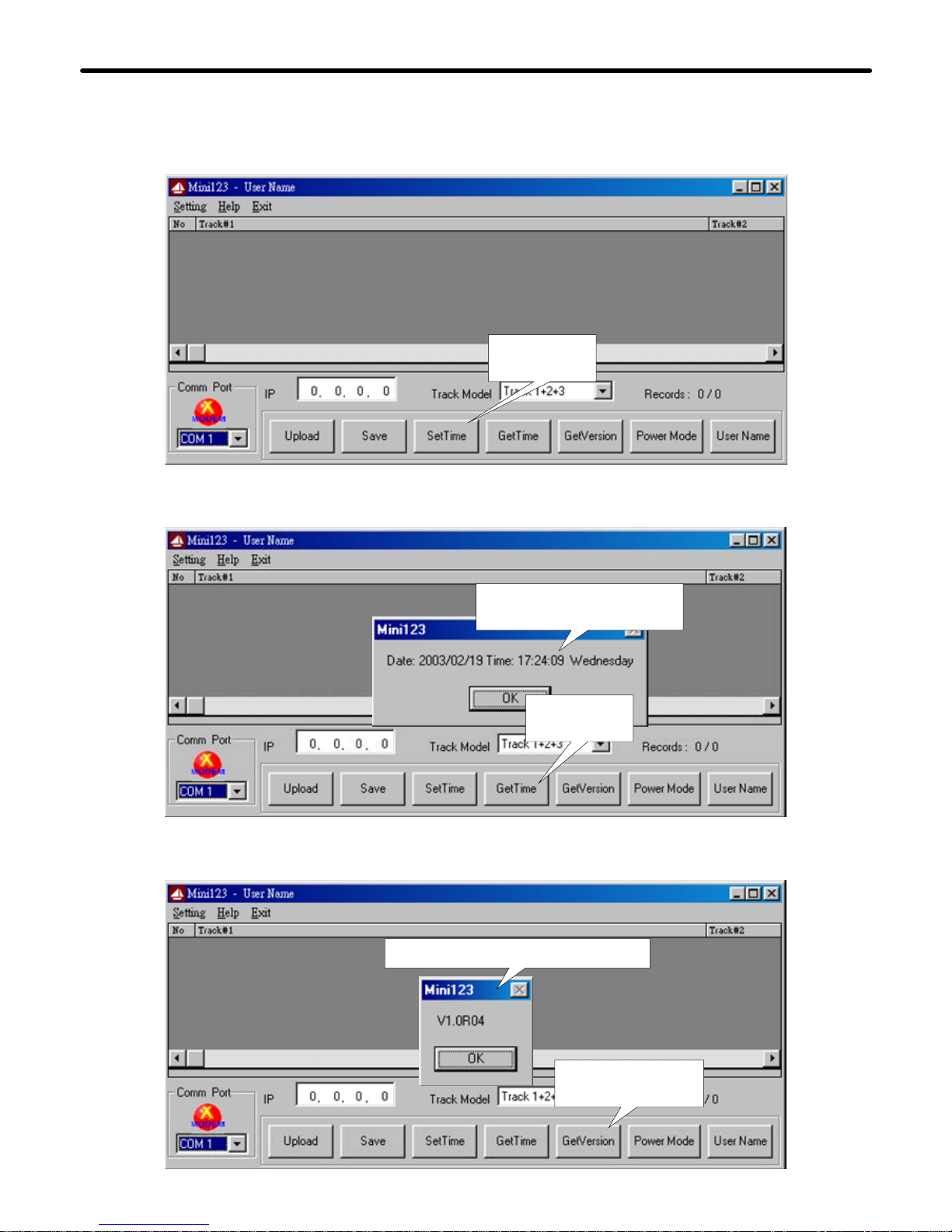
ENTER
GET VERSION
STEP 4 :ENTER GET TIME
( TO SHOW THE DATE&TIME IN Mini123 WHEN NEEDED)
STEP 5 : ENTER GET VERSION
( TO SHOW Mini123 FIRMWARE VERSON WHEN NEEDED)
Demo Software
- 10 -
STEP 3 : ENTER SET TIME TO SET PC CURRENT TIME TO Mini123
( WHEN NEEDED)
ENTER
SET TIME
NOTE: MAKE SURE YOUR PC CURRENT TIME IS CORRECT BEFORE YOU
SET PC TIME TO Mini123.
SHOW THE DA TE&TIME
IN Mini123
ENTER
GET TIME
Mini123 FIRMWARE VERSION
Page 13
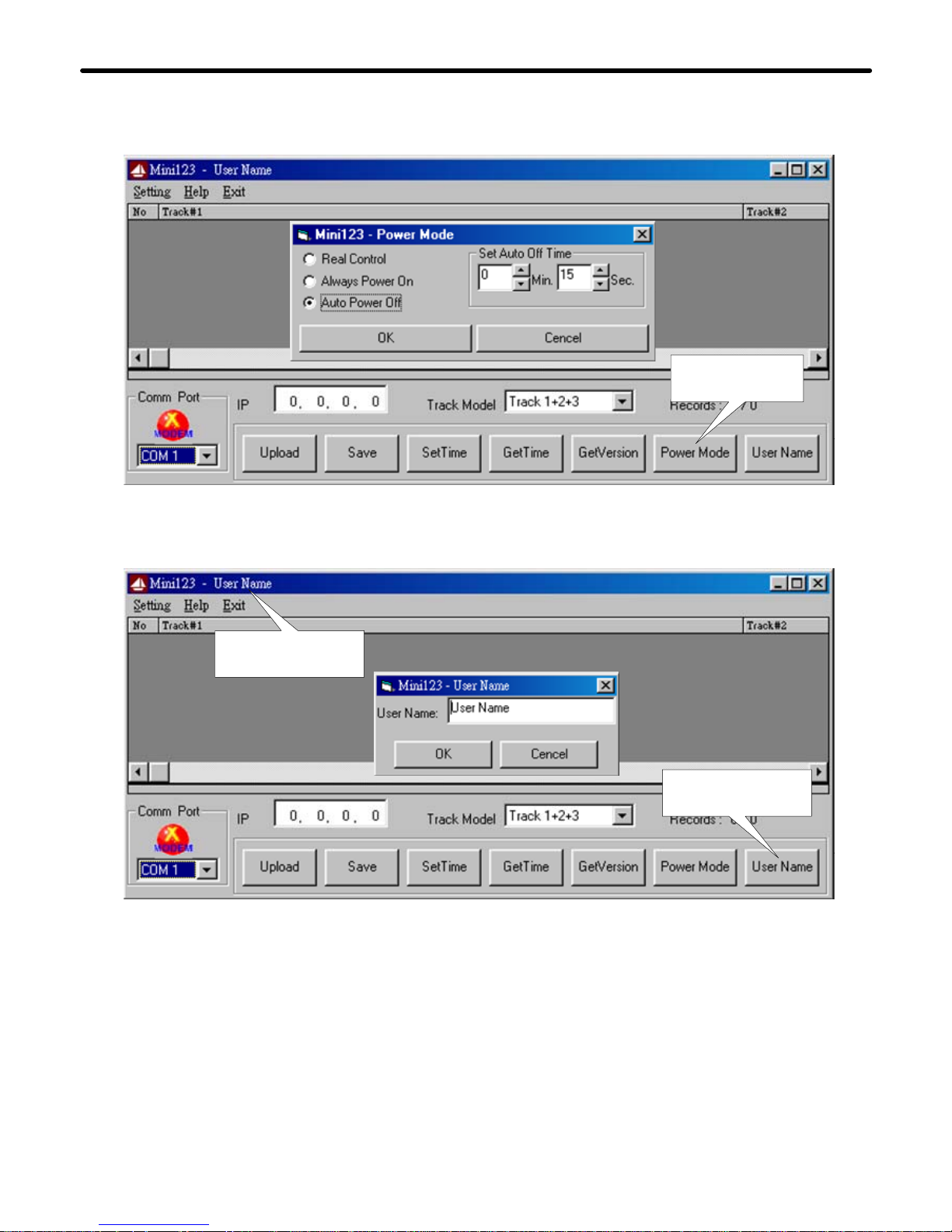
Demo Software
STEP 6 : ENTER POWER MODE (Timer set min 10 second /max 30 minute)
ENTER
POWER MO DE
STEP 7 : ENTER USER NAME , CURRENT USER NAME
ENTER
USER NAME
- 11 -
DISPLAY
USER N A M E
Page 14
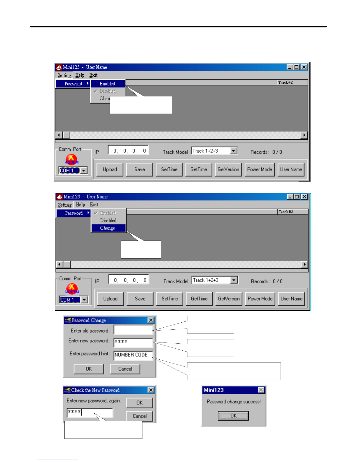
Demo Software
- 12 -
Change
Password
STEP 8 : ENABLE PASSWORD FUNCTION
Setting password
Function Enable
STEP 9 : CHANGE PASSWORD AND SET UP PASSWORD HINT.
Reenter n ew password
for confirmation
Default is
blank
Within 10
digits
Enter any character for
reminding of password
NOTE : IF YOU RESTART Mini123 SOFT W ARE, YOU HAV E TO ENTER PA SSWORD TH EN
AFTER YOU HAVE ENABLED PASSWORD FUNCTION.
Page 15
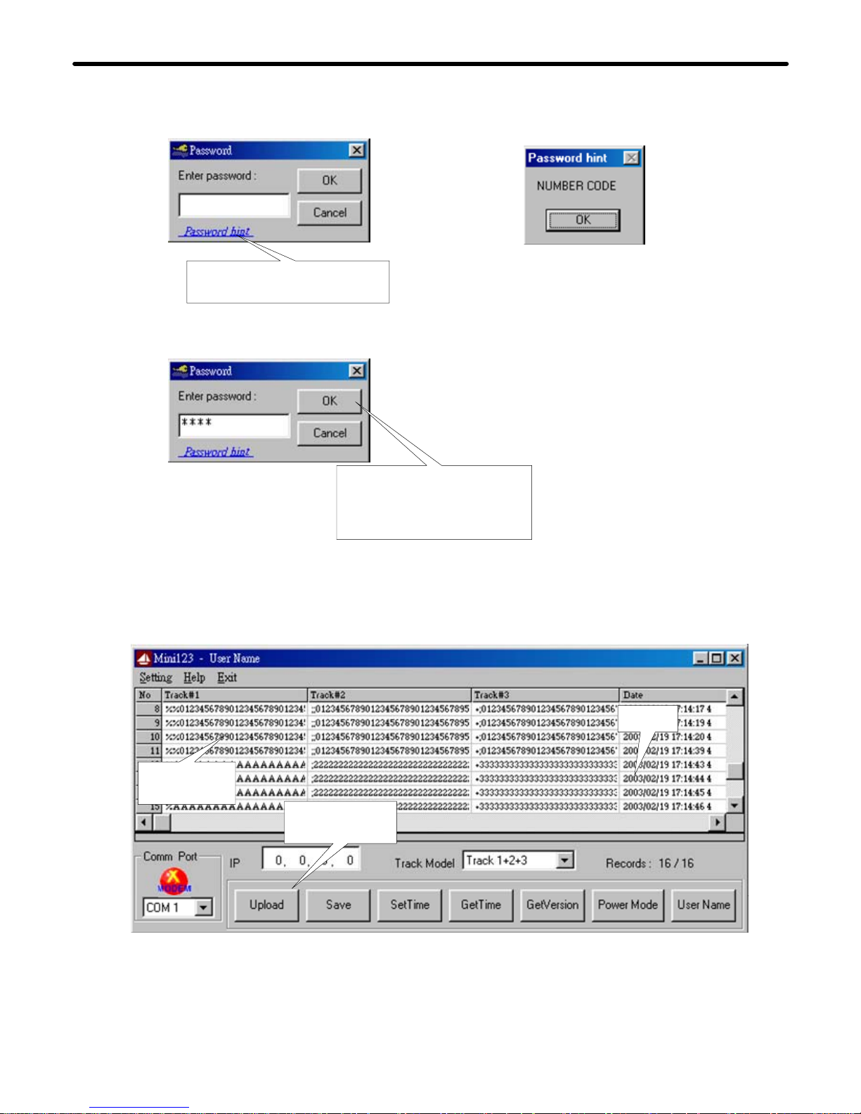
STEP 11 : ENTER UPLOAD TO UPLOAD DATA
PRESS
UPLOAD
UPLOAD
DATA
DATE
- 13 -
Demo Software
Enter passw ord hint for
reminding of password
Enter correct passw ord
according to the showed
hint, and it will enter
Mini 12 3 p r og ram.
STEP 10 : THE FUNCTION OF PASSWORD HINT.
Page 16
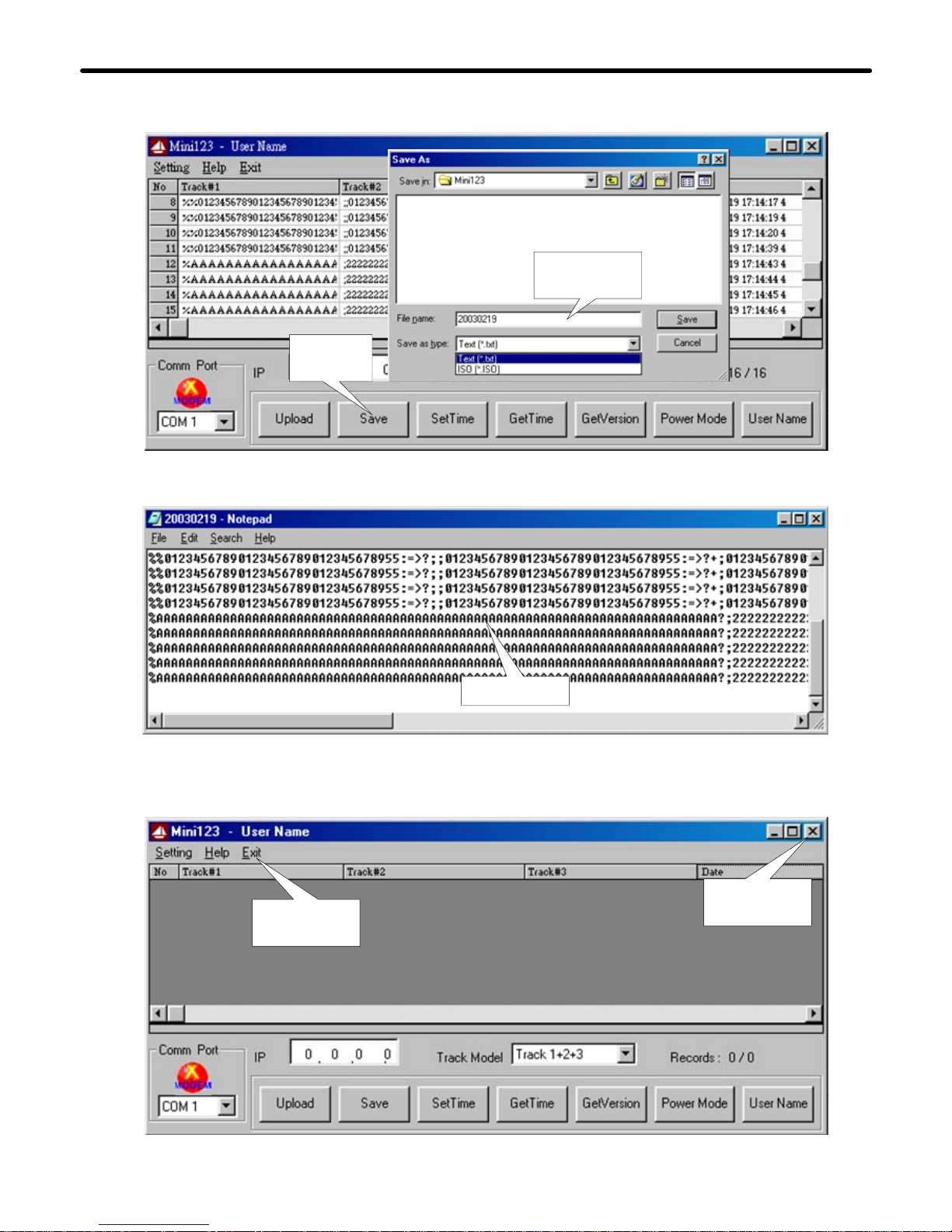
- 14 -
Demo Software
STEP 12 : ENTER SAVE TO SAVE DATA ( Pls refer to the remarks Connect to
PC in page 8. )
DATA
STEP 13 : SAVE DATA TO A FILE
STEP 14 : EXIT Mini123 SOFTWARE
ENTER
EXIT
ENTER
SAVE
ENTER
EXIT
CURRENT
FILENAME
Page 17
Specifications
Magnetic Stripe Card :
RS232 Int er fa ce :
Power Supply :
Dimensions :
Mounting :
Environment :
TRACK 1 / IATA / 210 bpi / 79 Alphanumeric Characters
TRACK 2 / ABA / 75 bpi / 40 Numeric Characters
TRACK 3 / Thrift / 210 bpi / 107 Numeric Character s
RS232 , Half-Duplex , 8N1 , 9600 bps
Battery Power :
CR2032 3 Volt and Low Battery Detect
AC
DC
External Power from RS23 2 Pin 4 Data Termi nal Ready (D TR)
L 50 x W 30 x H 38 mm
%
C/F
Operating Temp : 0 ~ 55 Deg.C
Storage Temp : -10 ~ 55 Deg.C
Humidity : 10 ~ 90 % relative
Portable or Any surface
- 15 -
RS-232
1 2 3
MC
GNET
VER 1.2
Communication Protocol :
Net Version 1.2 (GNET V1.2)
Memory Size for Storing Data :
RTC
CLOCK :
CMOS Serial Flash Memory 512K bytes
Real Time Clock (RTC) module and back-up capacitor
Up to 2048 records ( 256 Bytes / Record )
2048
REC QUEUE
BATTERY
2032
USB Inter face ( for DT105U )
USB V1.1 & USB HID Class V1.0
RTS ( Request To Send ) & DTR ( Data Terminal Ready ) be used
USB
Ver 1.1
Page 18
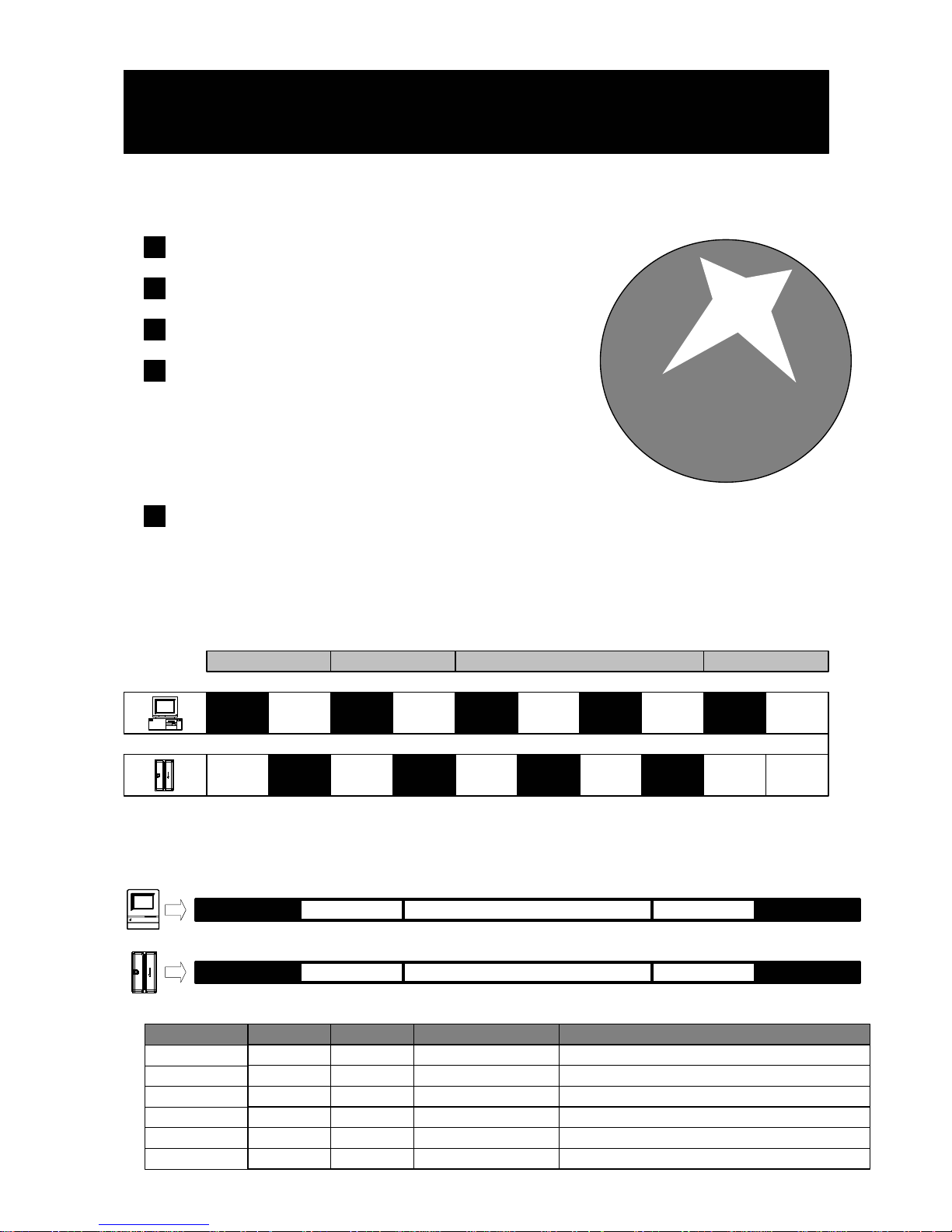
ACK
Communication Protocol
TX1
ACK
RX
NACK
TX2 TX4RX
RX
ERR
TIME
OUT
RX1 RX2
RX
NO
RX4
TX3
WAIT
RX
ACK
RX
NACK TIME OUT
Support TTY (TELE TYPE) OPERATION Use TTY to send commands and messages.
NACK
TX3
RX3
NACK
GNET FEATURES
Simple handshaking One enquiry one answer back.
Multi-link capability
Expandability GNET provides 4 major functions:
1. POLLING
2. LOGIN / LOGOUT
3. DATABASE
4. INFORMATION
Also can be expandable.
Simple format
Use ASCII value for each field and use Separator "," between two
Fields.
GNET Handshaking
GNET
V1.2
- 16 -
STX CMD CONTENTS CHKSUM CR
GNET PACKET
STX
CMD
CONTENTS
CHKSUM
CR
2 ^B Start of Text02
STX REPLY CONTENTS CHKSUM CR
ITEM Dec Control Key FunctionHex
13 ^M Carriage Return0d
Ascii Ascii Command CodeAscii
Ascii Ascii Contents DataAscii
Ascii Ascii Check SumAscii
REPLY (78) 65 (N) A (Negative) Acknowledge(4e) 41
Page 19
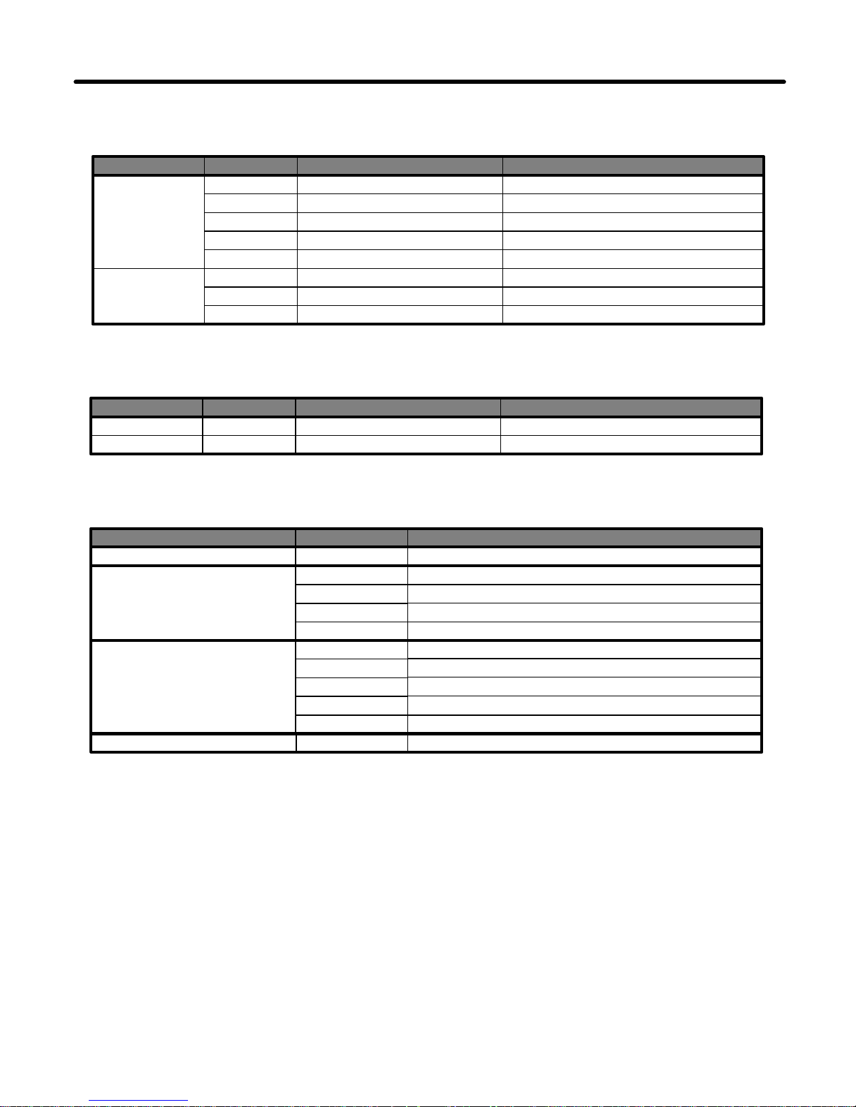
Commun ica tion Pr otocol
Command Index Table
Topic
SETTING
Command
F
S
T
Contents
-
Date,Time,Week
-
Description
Get Product Version
Set Date,Time and Week
Get Date and Time
- 17 -
Reply Index Table
ACK
NAK
Topic Reply
A
N
Reply Information
Contents
See Error Index Table
ACK+Information
Description
NAK+Information
Error Index Table ( For Reply NAK )
ACCESS LEVEL
COMMAND CODE
Topic
Error Inde x
00
01
Access Denied or Password Error
Description
Command packet is too long
DATABASE
FILE
02
03
Command packet is empty
Command code is out of range
04
05
Illegal Command or Data
Database and Register is Empty
06
Record number is out o f rang e
07
08
Check Sum Error
Memory Not Enough
0A
File Not Exist
DATABASE
N
G
E
-
Number
-
Get Number of Record
Read Record by Numb er
Erase All Record
09
Action Failure
C
B
Number+Param+ChkSum
Number
Set Register by Number
Get Register by Number
Page 20
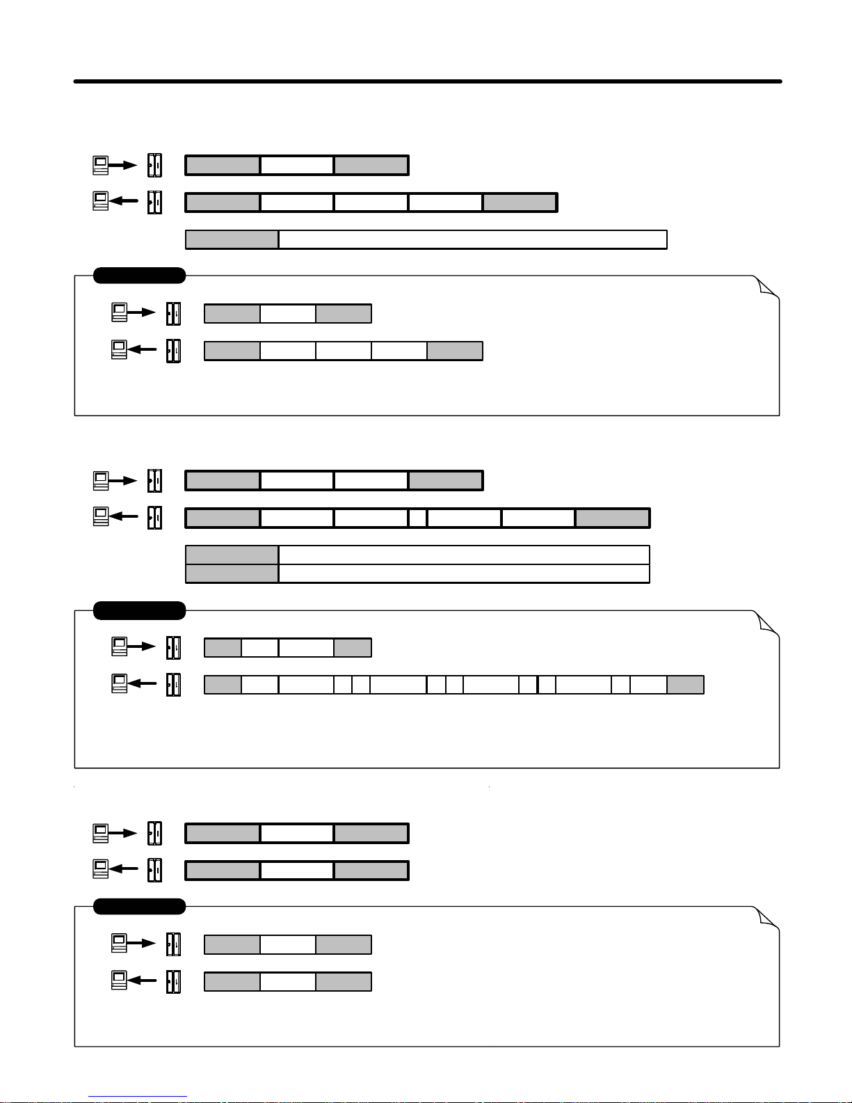
Commun ica tion Pr otocol
3. ERASE ALL RECORD :
STX E CR
STX A CR
02 E 0d
ERASE ALL RECORD
02 A 0d
EXAMPLE
- 18 -
1. GET NUMBER OF RECORD :
STX N CR
STX A CR
02 N 0d
The Total of Record Count : 12
02 A 0d
EXAMPLE
NUMBER
000C
CHKSUM
NUMBER Record Count . 4 By t es W idth ( 0000h ~ 00 80h )
14
2. READ RECORD BY NUMBER :
STX G CR
STX A CR
02 G 0d
Read Record Number : 12
TRACK1 ID : A BCD , TRACK2 I D : 2222 , TRACK3 ID : 3333
02 A 0d
EXAMPLE
NUMBER
000B
CHKSUM
NUMBER Record Count . 4 By t es W idth ( 0000h ~ 00 7Fh )
C7
NUMBER
DATA,
DATA Record Data ( TRACK1 , TRACK2 , TRACK3 )
000B
, ABCD%? ; ?2222 + ?3333
Page 21
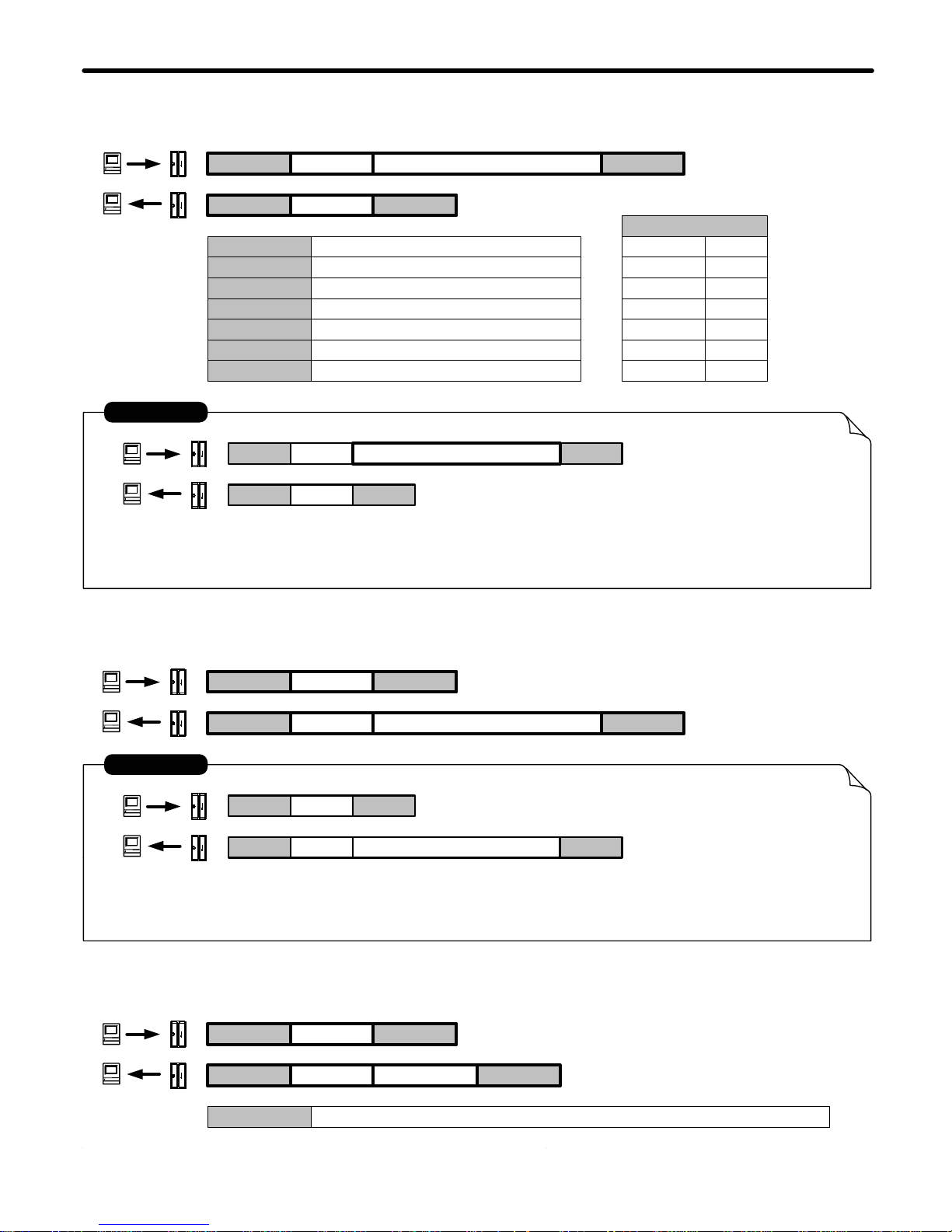
Commun ica tion Pr otocol
4. SET DATE AND TIME :
STX S CR
STX A CR
02 S 0d
Set Date = 2000 / 5 / 5
Set Time = 12 : 30 : 00 , Friday
02 A 0d
YYYYMMDDhhmmssw
200005051230006
EXAMPLE
YYYY
MM
DD
hh
mm
ss
5. GET DATE AND TIME:
STX T CR
STX A CR
02 T 0d
Get Date : 2000 / 11 / 8
02 A 0d
EXAMPLE
Get Time : 14 : 20 : 31 , Wednesday
YYYYMMDDhhmmssw
200011081420314
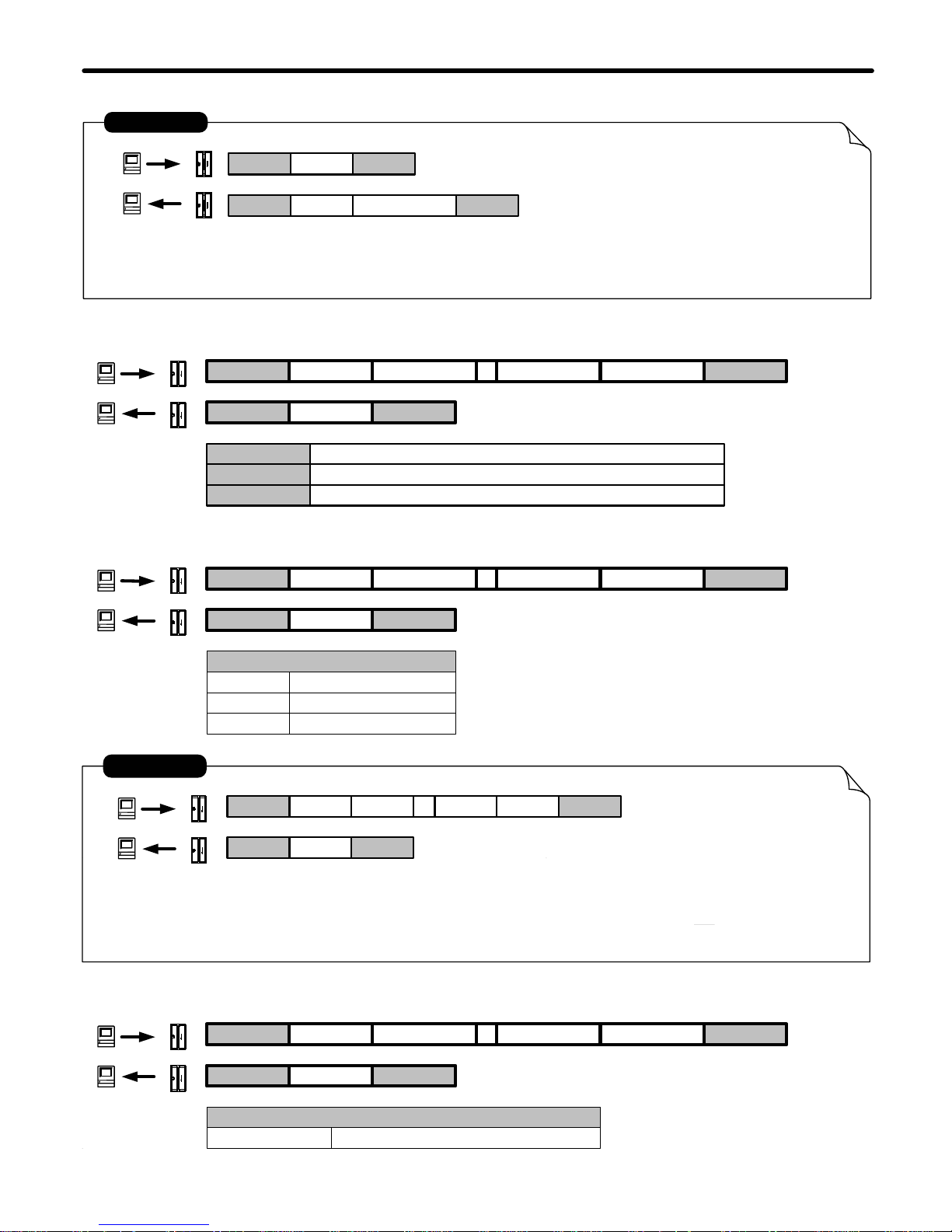
6. GET PRODUCT VERSION :
STX F CR
STX A CR
VxxRmm , Vxx : Firmware Version x.x , Rmm : Modify mm TimesVERSION
VERSION
Year (1980 - 20xx )
Month (01 - 12 )
Date ( 01 - 31 )
Hour ( 00 - 23 )
Mintue ( 00 - 59 )
Second ( 00 - 59 )
- 19 -
W Week ( 1 - 7 )
Week
SUN
MON
TUE
WED
THU
FRI
SAT
1
2
3
4
5
6
7
Page 22
Commun ica tion Pr otocol
02 F 0d
Firmware Version = 1.0
Modify times = 0
02 A 0dV1.0R00
EXAMPLE
- 20 -
7. SET REGISTER :
STX C CR
STX A CR
REGISTER
REGISTER , PARAM CHKSUM
PARAM
Register Address . 2 Bytes Widt h ( 00h ~ FFh )
Set Parameters of Register
7-1. SET POWER MODE :
STX C CR
STX A CR
12 , MODE CHKSUM
MODE
"00"
"01~FE"
Real Control
Auto Power OFF
02 C 0d
Write to Parameter Table Address : 12 h
Set Power Mode : Real Cont rol
CHKSUM= 43h(C) + 31h(1)+ 32h(2) + 2C h(,) +30h(0) + 30h(0) = 132h
= 33h(3) + 32h(2)
02 A 0d
EXAMPLE
12 , 00 32
Modem : 2400
Non- modem : 9600
"FF" Always P o wer ON
7-2. SET AUTO POWER OFF TIME (LOW BYTE) :
STX C CR
STX A CR
10 , SECL CHKSUM
SECL
"00-FF" 00h-FFh (0-255)/2 Second
CHKSUM C + REGISTER + , + PARAM
Page 23
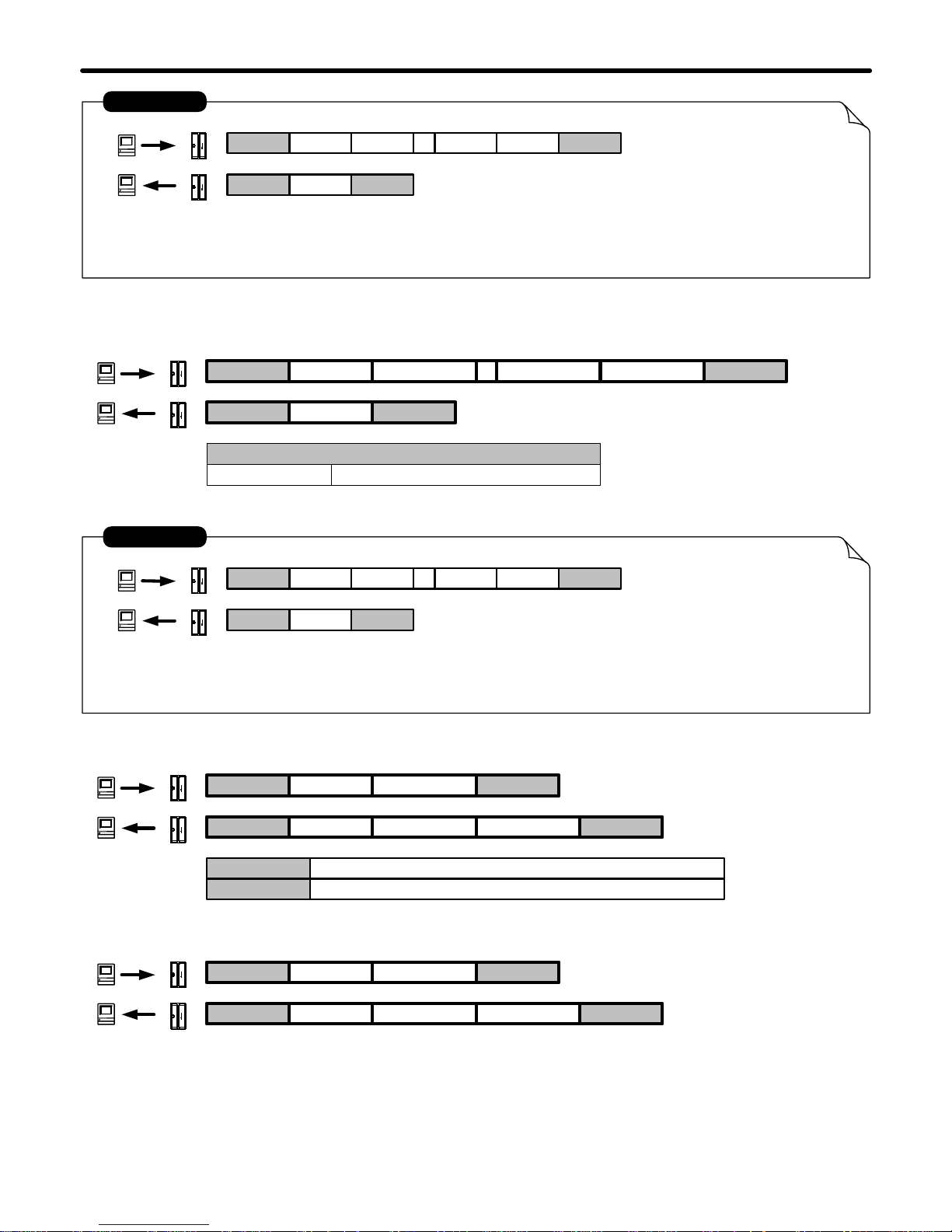
02 C 0d
02 A 0d
EXAMPLE
10 , 0A 41
Modem : 2400
Non- modem : 9600
Commun icat ion Pr otocol
STX C CR
STX A CR
11 , SECH CHKSUM
SECH
(00-FF)/2 *256 Seconds
02 C 0d
02 A 0d
EXAMPLE
11 , 02 33
Modem : 2400
Non- modem : 9600
- 21 -
7-3. SET AUTO POWER OFF TIME (HIGH BYTE) :
Write to Parameter Table Address : 11 h
Auto Power Off Time ( H ig h Byte) : 2*256/2 Second s
Write to Parameter Table Address : 10 h
Auto Power Off Time (Low Byte) : 5 Seconds
8. GET REGISTER :
STX B CR
STX A CR
REGSTER
REGSTER
PARAM CHKSUM
PARAM
Register Address . 2 Bytes Widt h ( 00h ~ FFh )
Set Parameters of Register
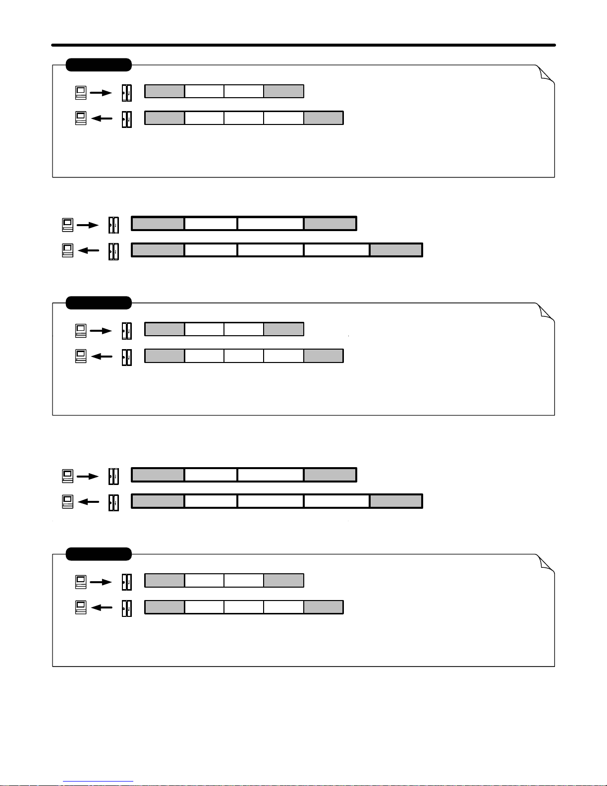
8-1. GET POWER MODE :
STX B CR
STX A CR
12
MODE CHKSUM
Same 7-1. SET POWER MODE
"00-FF"
Page 24
- 22 -
02 B 0d
Write to Parameter Table Address : 12 h
Get Power Mo de : Real Control
02 A 0d
EXAMPLE
12
00 A1
Modem : 2400
Non- modem : 9600
Commun icat ion Pr otocol
8-2. GET AUTO POWER OFF TIME (LOW BYTE) :
STX B CR
STX A CR
10
SECL CHKSUM
02 B 0d
02 A 0d
EXAMPLE
10
0A B2
Modem : 2400
Non- modem : 9600
STX B CR
STX A CR
11
SECH CHKSUM
02 B 0d
02 A 0d
EXAMPLE
11
02 A3
Modem : 2400
Non- modem : 9600
8-3. GET AUTO POWER OFF TIME (HIGH BYTE) :
Get Paramet er F rom Parameter Table Address : 11 h
Auto Power Off Time P eri od (High Byte) : 2*256/2 Seconds
Get Paramet er F rom Parameter Table Address : 10 h
Auto Power Off Time Period (Low Byte) : 5 Seconds
Same 7-3. SET AUTO PO WER OFF (HIGH BYTE)
Same 7-2. SET AUTO POWER OFF TIME (LOW BYTE )
Page 25
- 23 -
USB Driver Setup
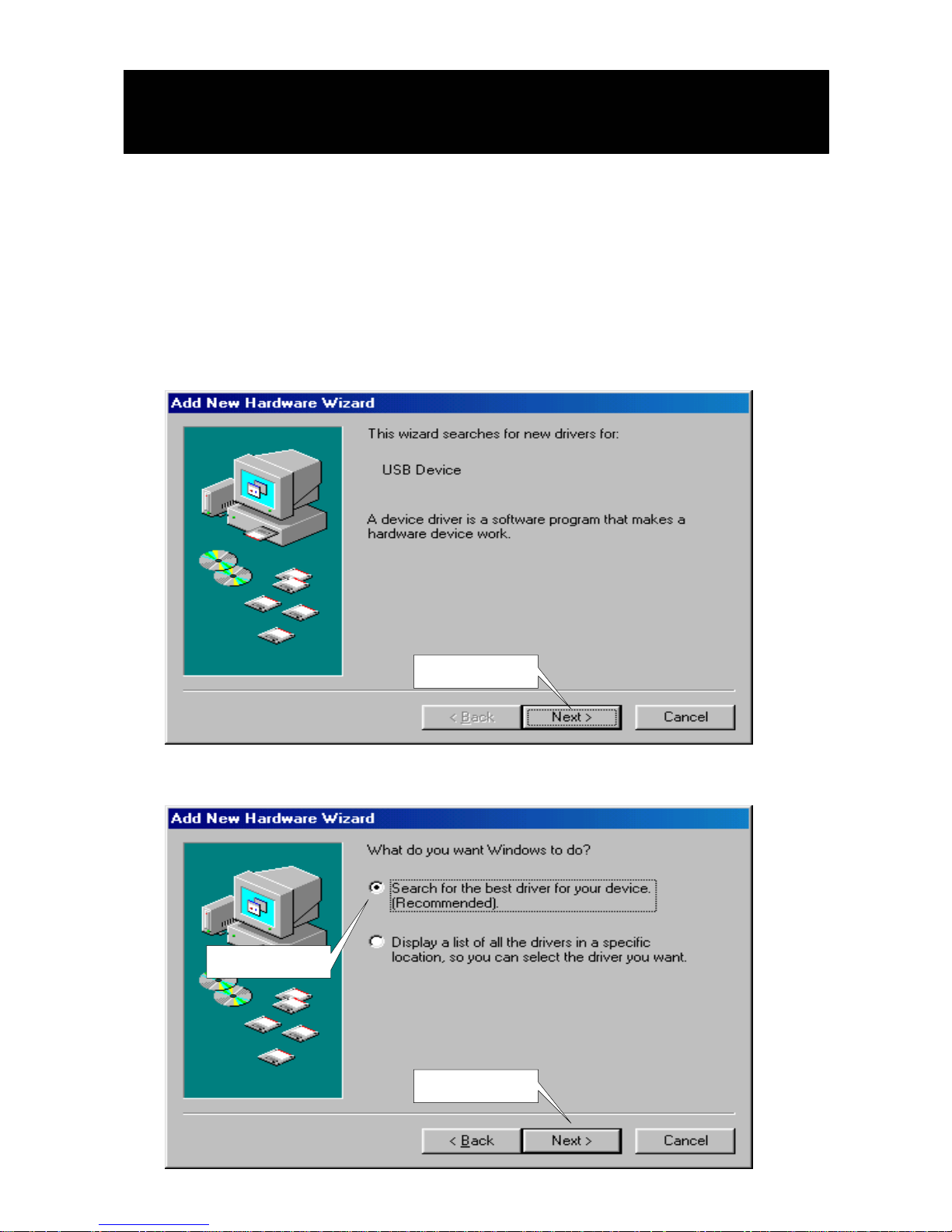
Driver Softwa r e Installatio n - For WAS-1571 only
1.Connect WAS-1571 into the USB PORT of your Computer first.
2.Under Windows 98/2000/Me/XP,put DISK5196 into the cd-rom disk
driver,it will automatically install the USB232/422/485 Driver
Software into your Computer by following the steps as below:
1. This wizard searches for new drivers for USB Device
Clic k Next
Clic k Next
Select this
2. What do you want Windows to do ?
Page 26
- 24 -
USB Driver Setup
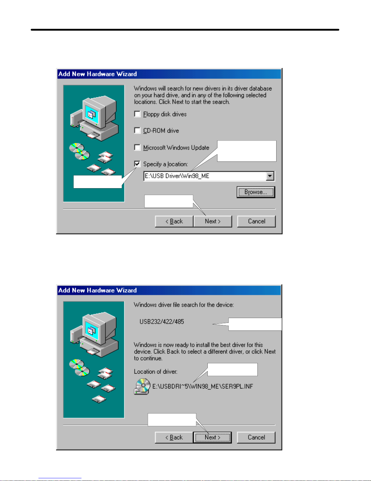
3. Select Searching locations for new driver
4. Windows is now ready to install the best driver
Give the path
location
Select this
Click Next
Device name
Path location
Click Ne xt
Page 27
USB Driver Setup
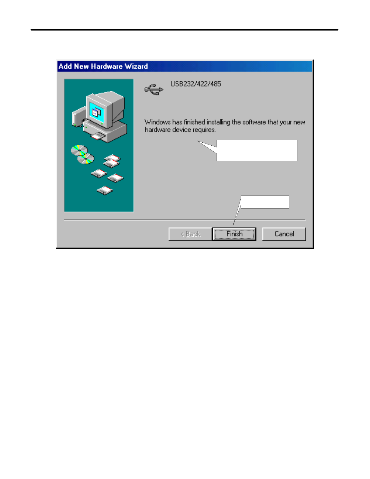
5. Windows has finished installing the software
Finish driver software
installation
Click Finish
- 25 -
Page 28
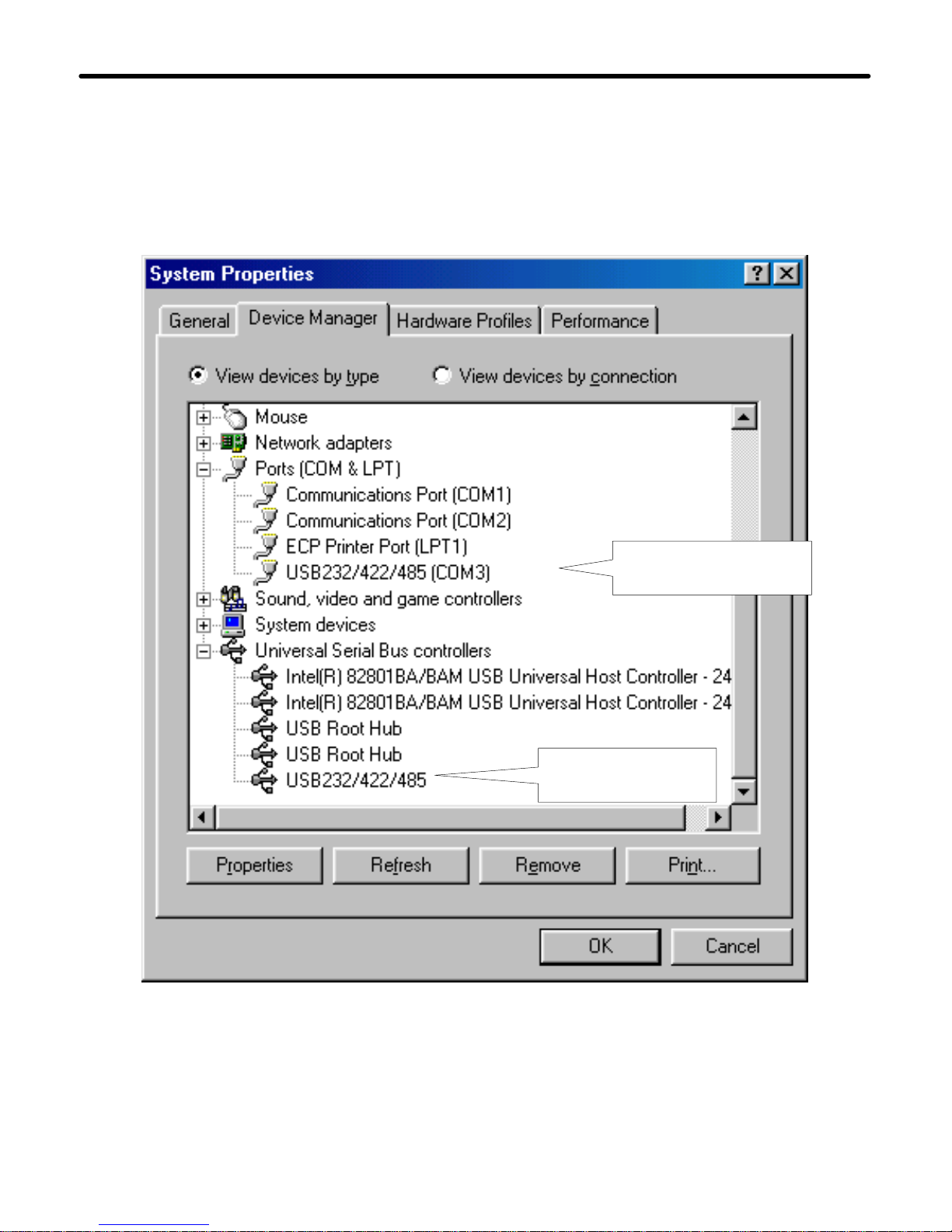
USB Driver Setup
6. Make sure if the driver software installation is finished
Connect WAS-1571 unit into the USB port of the computer and then Click
" Start " ->" Settings " -> " Control Panel " -> " System " ->" Device
Manager " to see if there are "USB232/422/485(COM3)" at Ports (COM &
LPT) and "USB232/422/485 "at Universal Serial Bus controllers.
USB232/422/485
is here
- 26 -
WAS-1571
connected at COM3
 Loading...