

Page 1
1
Remote Power Management Solution for Crashed Network Devices
USER MANUAL
Version: 2203 (MNT.NBU.7322 or higher)
!
!
!
!
!
!
!
!
!
!
!
!
!
Page 2

2
!"#$%&'(&)'*+%*+,&
)-".+%/&01&2*+/'345+6'*777777777777777777777777777777777777777777777777777777777777777777777777777777777777777777 8!
1.1.##Introduction.................................................................................................................................................3#
1.2.# Hardware#Specification ................................................................................................................4#
1.3.##Network#Diagram......................................................................................................................................5#
1.4.##LED#Indicators#Explained......................................................................................................................6#
)-".+%/&91&:"/3;"/%&<%+4. 777777777777777777777777777777777777777777777777777777777777777777777777777777777777 =!
)-".+%/&81&<'(+;"/%&>&?%#&<%+4.&@A'/&B3C"*5%3&D,%/E 77777777777777777777777777777777777777777 F!
3.1.##Introduction.................................................................................................................................................8#
3.2.##How#to#Locate#&#Access#IP#Switch#in#LAN......................................................................................8#
3.2.1%%Locate%IP%Switch%in%LAN%using%Utility%program........................................................................ 9%
3.2.2%%Locate%IP%Switch%in%LAN%using%fixed%IP......................................................................................... 9%
3.3.##How#to#Access#IP#Switch#from#WAN#–#using#DDNS ................................................................. 11#
3.4.##How#to#Access#IP#Switch#from#WAN#-#using#Google#Talk / #Hangouts .............................. 11#
3.4.1.%%How%to%Setup%Google%Talk/%Hangouts%for%the%IP%Switch ....................................................12%
3.5.#How#to#Access#IP#Switch#from#WAN#–#Using#Skype..................................................................14#
3.6.##How#to#Upgrade/#Re-Flash#Firmware........................................................................................... 18#
)-".+%/&G1&2H&<;6+5-&?%#&D,%/&2*+%/("5% 77777777777777777777777777777777777777777777777777777777777777 9I!
4.1.##Information............................................................................................................................................... 20#
4.2##Configuration ............................................................................................................................................21#
4.3##Log#Information ....................................................................................................................................... 34#
4.4##Help ...............................................................................................................................................................34#
)-".+%/&J1&!/'4#$%,-''+6*K&!6.,777777777777777777777777777777777777777777777777777777777777777777777777777 8=!
B..%*36L&B1&M'4+%/&)'*(6K4/"+6'*777777777777777777777777777777777777777777777777777777777777777777777777 GI!
B..%*36L&N1&2H&B33/%,,O&<4#*%+&"*3&P"+%;"Q 777777777777777777777777777777777777777777777777777777 G9!
B..%*36L&)1&P$',,"/Q 7777777777777777777777777777777777777777777777777777777777777777777777777777777777777777777 GG!
P''K$%&!"$R&9&<+%.&B4+-%*+65"+6'* 77777777777777777777777777777777777777777777777777777777777777777777777 GJ!
Page 3
3
Chapter 1: Introduction
1.1. Introduction
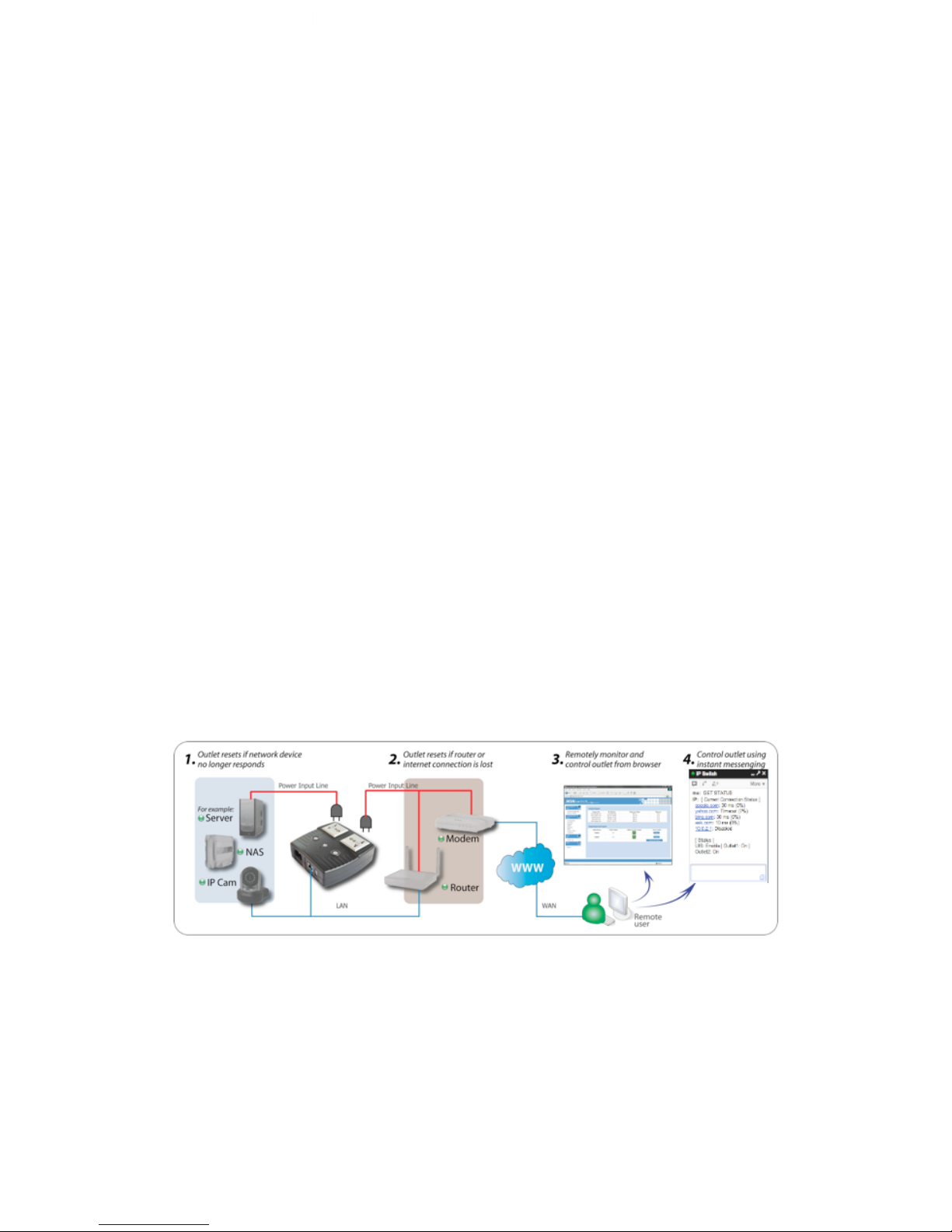
IP Switch is designed to automatically power-cycle either one or both of its outlets
when either;
a) Internet connectivity is lost (resets Router/Modem to restart it), or
b) the network device being monitored is no longer responding in LAN.
It can also be used to:
a) remotely control outlets via instant messaging tool like Google Talk/ Hangouts, or
a Web User Interface.
b) perform scheduled power On / Off / Reset
c) manually control outlets by disabling the UIS (Uninterruptable Internet System)
function
IP Switch is useful where the Internet connection and accessibility to a remote site is
critical. It can be setup so that when the remote Mobile Broadband / Cable / Satellite
/ DSL / T1, etc. connection drops or if the remote router freezes-up, it will auto reset
the router to re-gain connectivity. IP Switch is also useful for:
1. Saving home users the trouble of constantly having to power-cycle their
router to re-gain Internet connectivity.
2. Resetting unresponsive device (for instance IP camera or NAS servers)
which otherwise will be inaccessible from remote.
3. IT Professionals who need to automatically or remotely reset devices
4. Preventing your connection from timing out or going dormant
5. Having devices on an automatic power schedule
Generalized description of network connection:
Hardware Specifications:
1. Built-in Web Server with 32-Bit RISC CPU.
2. 10/100Mbps Fast Ethernet Network Access.
3. Support IE or Java-Enabled Web Browser.
Page 4
4
4. Network Protocol: HTTP, TCP/IP, UDP, SMTP, Dynamic DNS, DNS Client,
SNTP, DHCP.
5. Operating Temperature: 0°C ~ 60°C; Operating Humidity: 10% ~ 90%
6. For indoor use only.
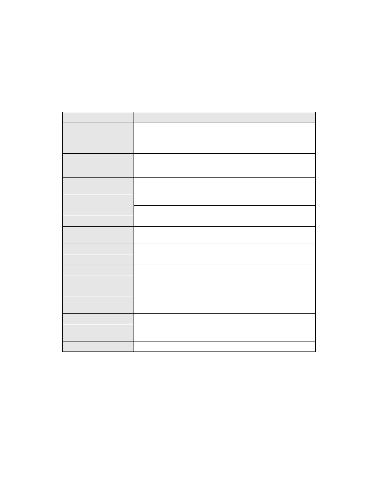
1.2. Hardware Specification
Model No:
UIS-322
Socket type
2x of either;
a) Universal socket (Type X)
b) USA (Type B, NEMA 5-15R)
AUST / China (Type I, AS / NZS3112, CCC)
Certifications
CE, FCC (tested to be compliant with FCC 47 CFR Part 2 and Part
15 Class B equipment regulations)
Electrical Rating
Input: 125~250V~50/60Hz
Output: 10A (for 2 sockets) & DC5V, 500mA (for USB port)
Breaker
10A (Thermal fuse)
Available Sockets
2x fixed
Internet Control-able
2x fixed socket
Power ON / OFF switch
Individual outlet power ON / OFF LED button
(Press & hold 2 seconds)
Power Indicator
Orange LED
Reset to Factory Default
Reset button located to the right of Ethernet port
Internet Indicator
Green LED
Web Server CPU
32-Bit RISC CPU
Supported browser
IE and Java
Supported Network
Protocols
HTTP, TCP/IP, UDP, SMTP, Dynamic DNS, DNS Client, SNTP,
BOOTP, DHCP.
Network Access
10/100 Base-T, RJ45 (Cat. 5)
Operating Environment
0°C to 60°C at 10% to 90% relative humidity.
For indoor use only.
Package
White Box
Page 5
5
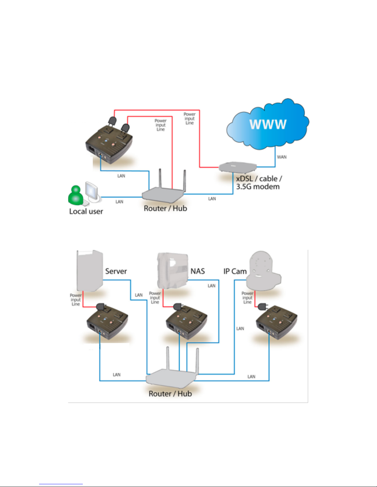
1.3. Network Diagram
The following Network diagrams applies to all IP Switch models.
Fig.1 IP Switch setup to perform auto reset of router and modem
Fig.2 IP Switch setup to keep Internet device alive.
Page 6
6
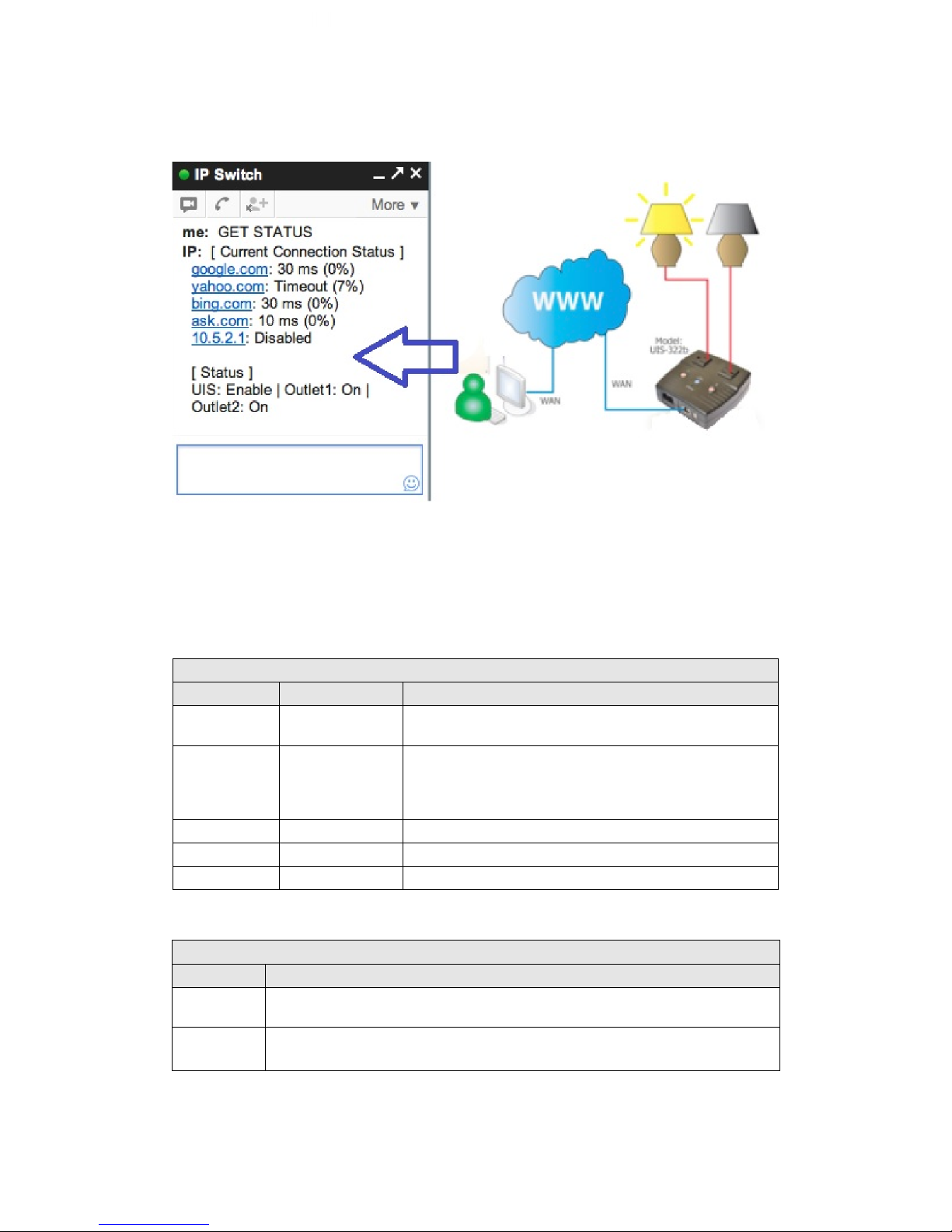
Fig.3 IP Switch setup for remote control via Google Talk/ Hangouts or thru Web User
Interface.
1.4. LED Indicators Explained
LED Status for Internet & Outlets
LED
LED status
Condition description
Internet
Solid Green
Internet connection available and UIS (Uninterruptable
Internet System) mode has been activated.
Internet
Blinking Green
There is internet connection. UIS mode button has not
been activated. With UIS enabled however, this means
that at least one of the target sites is not responsive
(regardless of being assigned or not)
Internet
OFF
There is no internet connection.
Outlet
Solid Orange
Outlet is powered ON
Outlet
OFF
Outlet is powered OFF
Fig.4 LED Indicator
LED Status on LAN Port
Light color
Condition description
Green
When On: Internet speed is at 100M
When flashing: Data transmitting / receiving
Yellow
On: Internet correspond speed is 10M
Flash: Data transmitting / receiving
Page 7
7
Fig.5 LAN LED Indicators
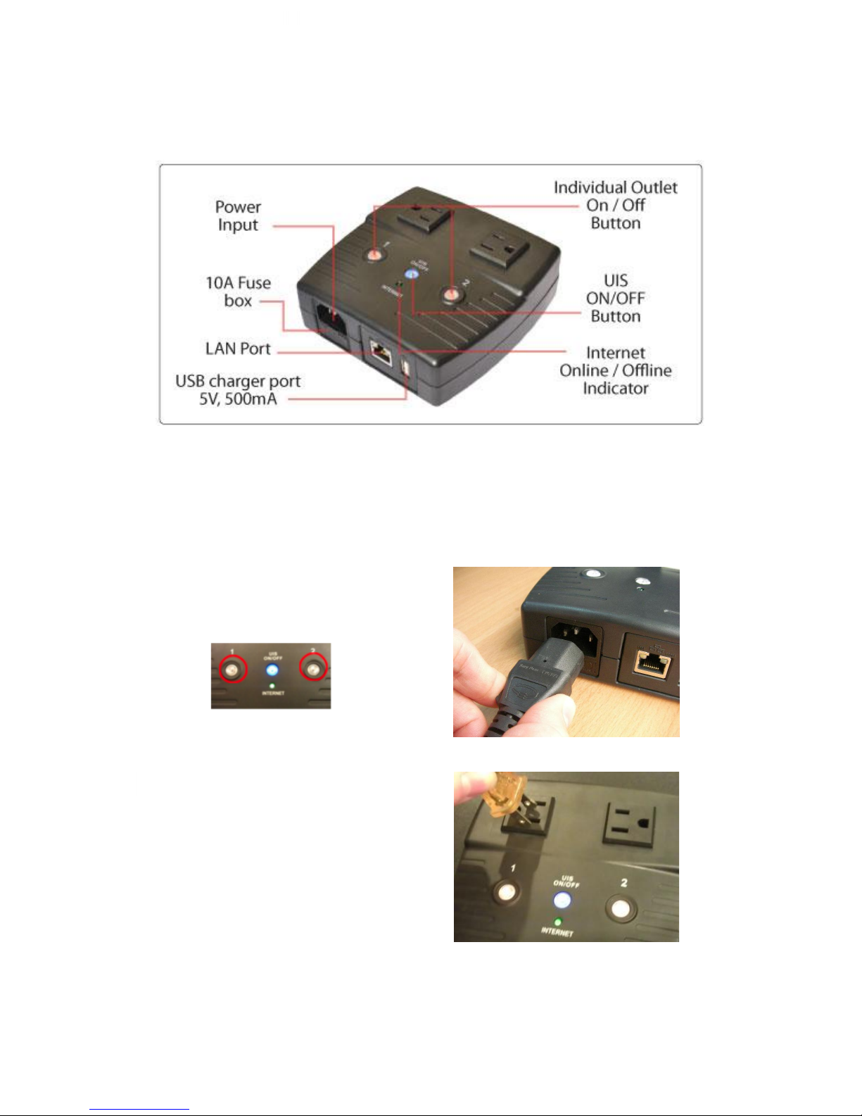
Fig.6 Description
Chapter 2: Hardware Setup
IP Switch hardware installation procedure:
Step 1:
Connect the power cord to device and wall
outlet. The two orange LED will light up,
indicating that the individual Outlet is ON.
Press the Orange LED for 2 seconds to
turn the Outlet On / Off.
Step 2:
Connect the power plug to IP Switch
outlet.
NOTE: In order for IP Switch to
maintain continuous Internet
connection or reset your modem/
router, the router power input must
be connected here.
Page 8
8
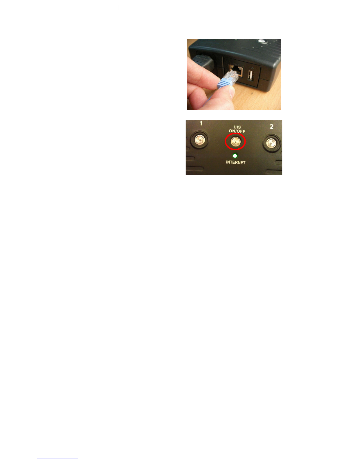
Step 3:
Connect LAN cable from your router.
Step 4:
Make sure the Internet LED light is
blinking to show that the internet
connection is ready.
Press and hold the “UIS On/Off” button
(about 2 seconds) to activate internet
protection, which will allow the switch to
auto reset upon loss of connection to the
Target sites (i.e web site addresses or
local IP addresses). This completes the
basic setup.
Chapter 3: Software & Web Setup (For Advanced User)
3.1. Introduction
IP Switch is designed to work without having to install any software (see hardware
setup above). However, for the advanced user, the unit can be customized and
configured for remote access. This gives the user further control over the power
ports.
There are two ways to remotely control the outlets (access from WAN);
a. Using DDNS and Port forwarding, see Section 3.3 or;
b. Using Google Talk/ Hangouts instant messaging tool, see Section 3.4.
3.2. How to Locate & Access IP Switch in LAN
IP Switch comes with a built-in Web User Interface (Web UI) that allows for more
advanced control over the unit. There are two ways of accessing the Web UI in LAN
(i.e. when both IP Switch and PC is connected to the same router).
1. Utility program (available for Windows only)
2. Use a fixed IP (when there’s no DHCP server).
*Note–You can also use any LAN program to locate the WebUI URL for example:
Mac: LANscan https://itunes.apple.com/us/app/lanscan/id472226235?mt=12
Windows: Wireshark or Angry IP Scanner
Page 9
9
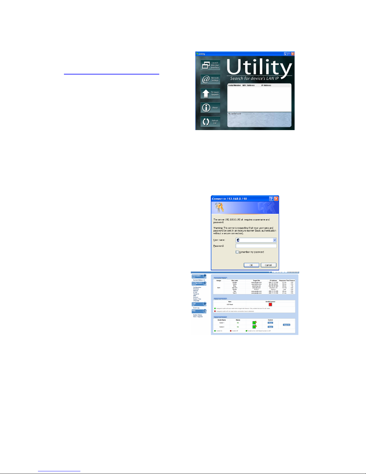
3.2.1 Locate IP Switch in LAN using Utility program.
Step 1:
Download the Utility program from
http://3gstore.com/ipswitchupdates and
install.
Once installed Utility will locate and list the
IP Switch units.
NOTE: Utility can only discover the IP
Switch units that are located within the
same LAN or network. Be aware that
certain things such as VPN, antivirus,
admin privileges, etc, can prevent
Utility from locating your device(s).
Utility will show LAN IP if units are
connected to a Router. If you are
connecting to your computer directly,
you will need to manually assign an IP
address to the device via the ‘Network’
tab, as well as manually set an IP for
your computer’s Ethernet adapter.
Step 2:
Click “Launch Web User Interface” to run
Internet Explorer (or your default browser)
and access the IP address of the unit.
A password dialog box will appear.
By default; Username/ password is:
admin/ admin. Press “OK” to proceed.
Step 3:
You will be logged into the IP Switch.
3.2.2 Locate IP Switch in LAN using fixed IP.
By default, the IP Switch should obtain an IP address automatically from your router
using DHCP. If for some reason it does not, press and hold the UIS button for 10
seconds and it will revert to a fixed LAN IP of 192.168.0.100.
To access IP Switch Web interface in this mode:
Page 10

10
Step 1:
Connect the LAN cable from IP Switch to your PC’s Ethernet port
Step 2:
Assign a fixed IP within the same subnet to your PC. Example: IP address -
192.168.0.20; Subnet Mask - 255.255.255.0; Gateway: 192.168.0.1
Step 3:
On your PC, launch a web browser and enter the IP: 192.168.0.100 - Login
username/ password: admin/ admin. You can now change this fixed IP address
to one that you prefer by going to Configuration Settings -> Network.
Page 11

11
3.3. How to Access IP Switch from WAN – using DDNS
The IP Switch Web User Interface (Web UI) can be accessed remotely from Wide
Area Network (WAN). To do so, you must have a public dynamic IP address from
your ISP (Internet Service Provider) - if you’re unsure about this, please contact your
ISP. Once you’ve confirmed that, proceed as follows;
i. Setup port forwarding at your router.
a. Log into your router setup / configuration page.
b. Most routers will have these settings under the Firewall / Port
Forwarding / Virtual server section. You will need to open (allow):
WAN Port 80; Type/Protocol: TCP. (NOTE: You may need to forward
port 80 to a different port if you have other devices on the netowrk using
that port)
and,
ii. Setup a Domain Name for your Dynamic WAN IP. Use 3rd Party DDNS
providers. To do so;
a. The following 3rd party DDNS providers below are supported;
• 3322.org
• DynDNS (Dynamic)
• DynDNS (Custom)
• myDDNS.com
• No-IP
b. Create a new user account and password.
c. Register a Domain Name for your current Dynamic WAN IP.
d. Log into your outlet via its local IP Address and navigate to →
Configuration Settings → Network → Dynamic DNS. Select
the service provider; enter the registered domain name, user
account, and password. Click Apply.
The IP Switch is now accessible remotely using the newly registered Domain Name.
For a description of Network → Dynamic DNS functions see section 4.2.3.
3.4. How to Access IP Switch from WAN - using Google Talk/
Hangouts
IP Switch supports Google Talk/ Hangouts, an instant messaging tool. Once setup,
user can get notifications and issue commands to check the status, as well as turn
on/off power or power-cycle certain ports using Google Talk/ Hangouts.
Before starting, you will need firmware version MNT.NBU.5326,
2.40.MNS.NBU.6311, or newer, as well as 2 Gmail accounts - 1 designated as the
IP Switch & 1 as the Control account.
Page 12

12
3.4.1. How to Setup Google Talk/ Hangouts for the IP Switch
Step 1:
From the Utility application, select
‘Launch Web User Interface’ -
when prompted, log in with the
default user name & password:
User Name: admin
Password: admin
NOTE: If Utility cannot locate your
Switch, please refer back to
section 3.2.1
Step 2:
Below the ‘Configuration Settings’
button on the left, select ‘Google
Talk’ or ‘Hangouts’ (depending on
your firmware version)
a. Towards the top left corner you’ll
notice ‘Status’ - by default this is
set to ‘Offline’ - You will need to
change this to ‘Online’
b. For the ‘Login ID’ enter the Gmail
Account associated for the Switch
(Example: [email protected]).
c. Now, enter the Password for the
same Gmail account in the
‘Password Field’
d. Under the ‘Add Contact
Accounts’ enter your control Gmail
account that will be used to control
the switch (Example:
e. Click ‘Apply’
Step 3:
Allow a few moments for IP Switch
to connect and Sign in. The
connection status will be shown on
the heading.
Page 13
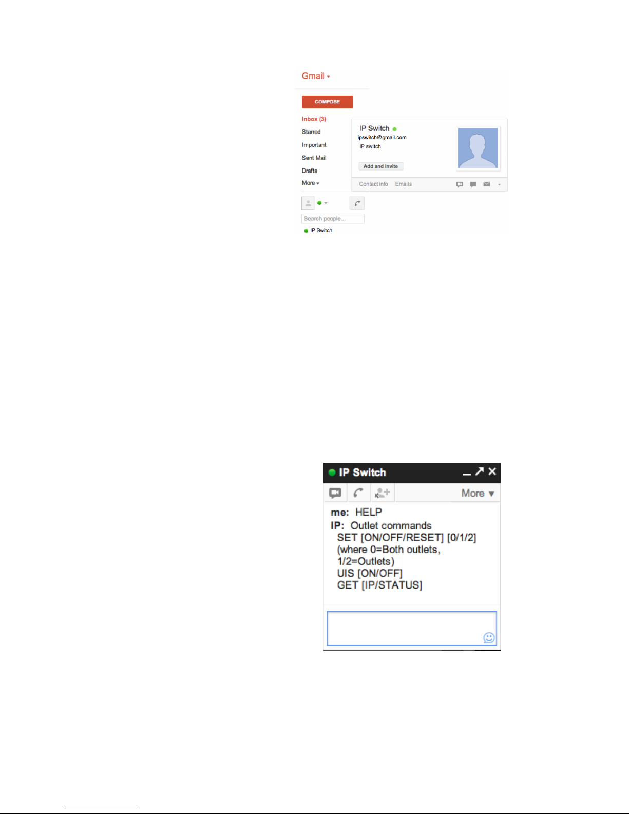
13
Step 4:
Once connected, you’ll want to log
into your control Gmail account. The
users listed in your Contact List will
receive a notification to add the IP
Switch as a ‘contact’.
Once added, you can control the IP
Switch by chatting with it.
NOTE 1: If you do not receive an ‘invite’ notification, you may need to
log into your IP Switch’s Gmail account to ADD CONTACTS directly from
there.
NOTE 2: Only the users listed in the CONTACT ACCOUNT section can
command IP Switch. If you are removed from this list, you will still be on
the IP Switch’s contact list within the Gmail account, but you will be
unable to send commands to it.
NOTE 3: If you are using Google 2-step authentication, see page 45 for
configuration steps.
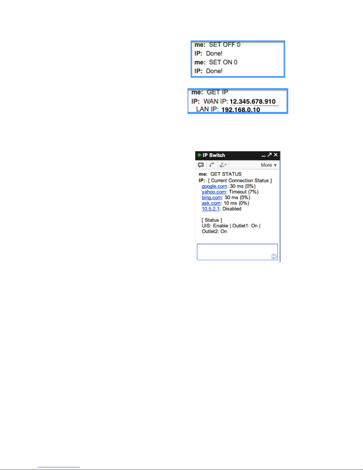
3.4.2. How to Control IP Switch using Google Talk/ Hangouts
After setting up and getting connected as
above. Bring up the IP Switch chat
window by inviting it to chat.
*Typing in anything other than the
Keywords will invoke IP Switch to
respond with “Please type HELP to list
available commands.”
Available commands are (non case
sensitive):
SET [ON/OFF/RESET] [0/1/2] (where
0=both outlets, 1/2=Outlets)
UIS [ON/OFF]
GET [IP/STATUS]
Page 14
14
SET ON / OFF / RESET command will
return a “Done!” once IP Switch has
completed the action.
GET IP command will return the WAN IP
and the unit’s LAN IP address.
*If port forwarding is set, but not the
domain name, user can still use WAN IP
to access the IP Switch Web User
Interface from internet.
GET STATUS command will return the
following information.
For [Outlet Status] the Outlet1 and
Outlet2 name can be assigned. This is
done via the local IP address of the IP
Switch ...→ Configuration →
Configuration → Outlet Setup.
*Allow time for the system to respond.
*NOTE: There is also a mobile
application called “Hangouts” that can
be used in this same manner. It is
available for Android and iOS.
3.5. How to Access IP Switch from WAN – Using Skype
As an alternative to the Google Talk/ Hangouts, you can now use Skype to
monitor and control your outlets.
Step 1: While connected to the same network as the 3Gstore IP Switch, open
a browser and enter this address: http://outlet (*only works on windows OS)
otherwise use the IP Address to the switch i.e. 192.168.0.197 or try using the
Utility program ( *Windows only Program)
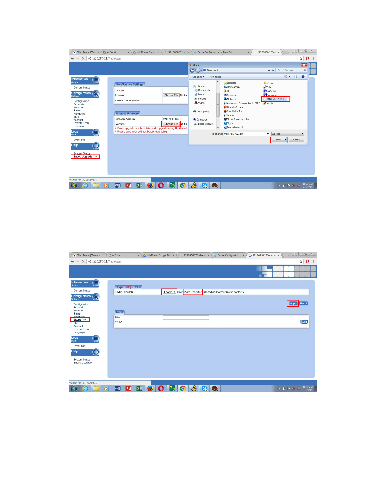
Step 2: Admin Screen
1. Select Save/Upgrade on the left hand side of the screen
2. In the Upgrade Firmware Section under Location Select Choose File
3. Locate the File you downloaded (usually under downloads)
4. Click Open
5. Click Apply
6. Uploading Firmware will prompt for a couple of minutes
Page 15
15
Step 3: Initiate Skype:
1. Under Configuration Settings Select Skype
2. In the Skype Function Section Click on Enable
3. Then Click on Auto Rebooter (a separate tab will open see Step 4)
3. Click Apply
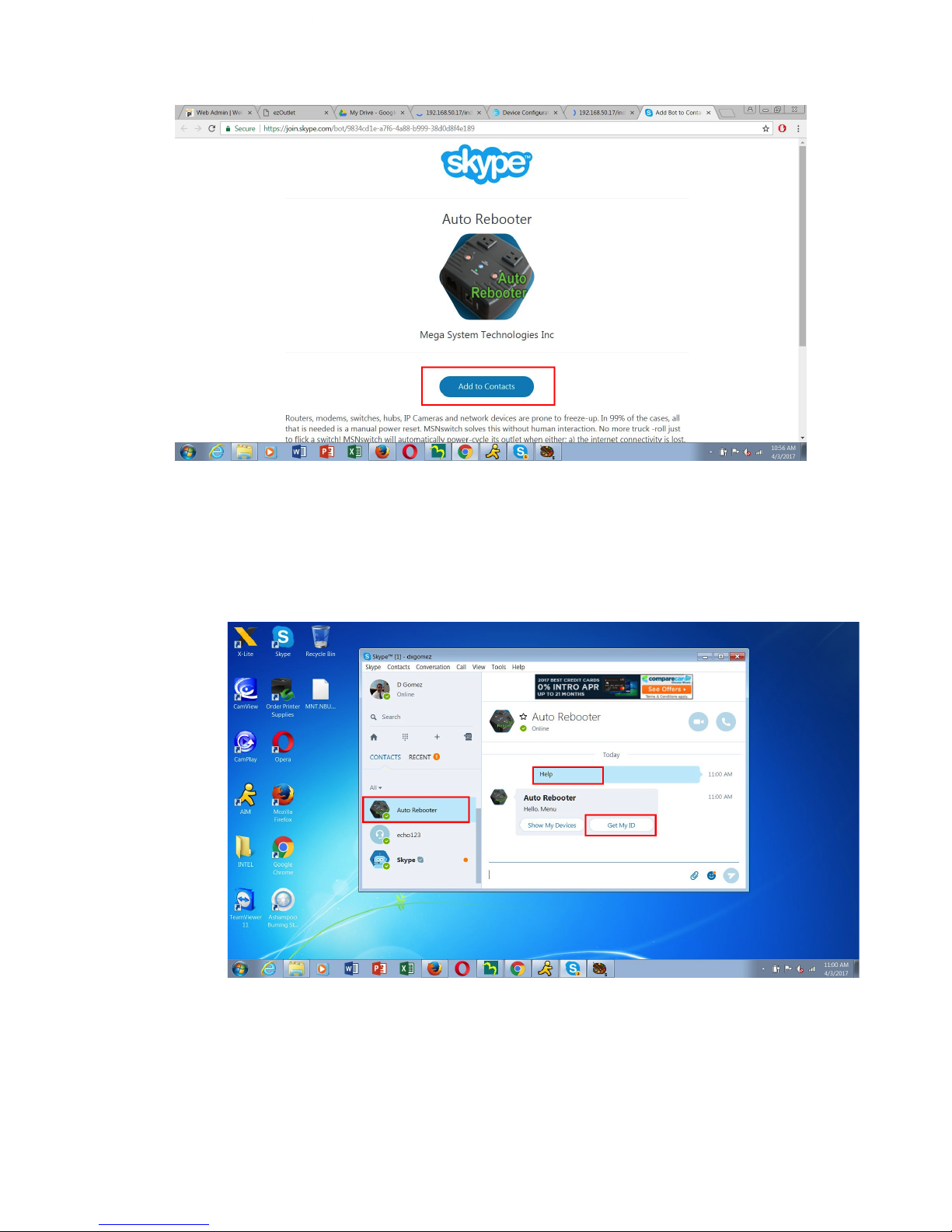
Step 4: Auto Rebooter
1. Click Add to Contacts
Page 16
16
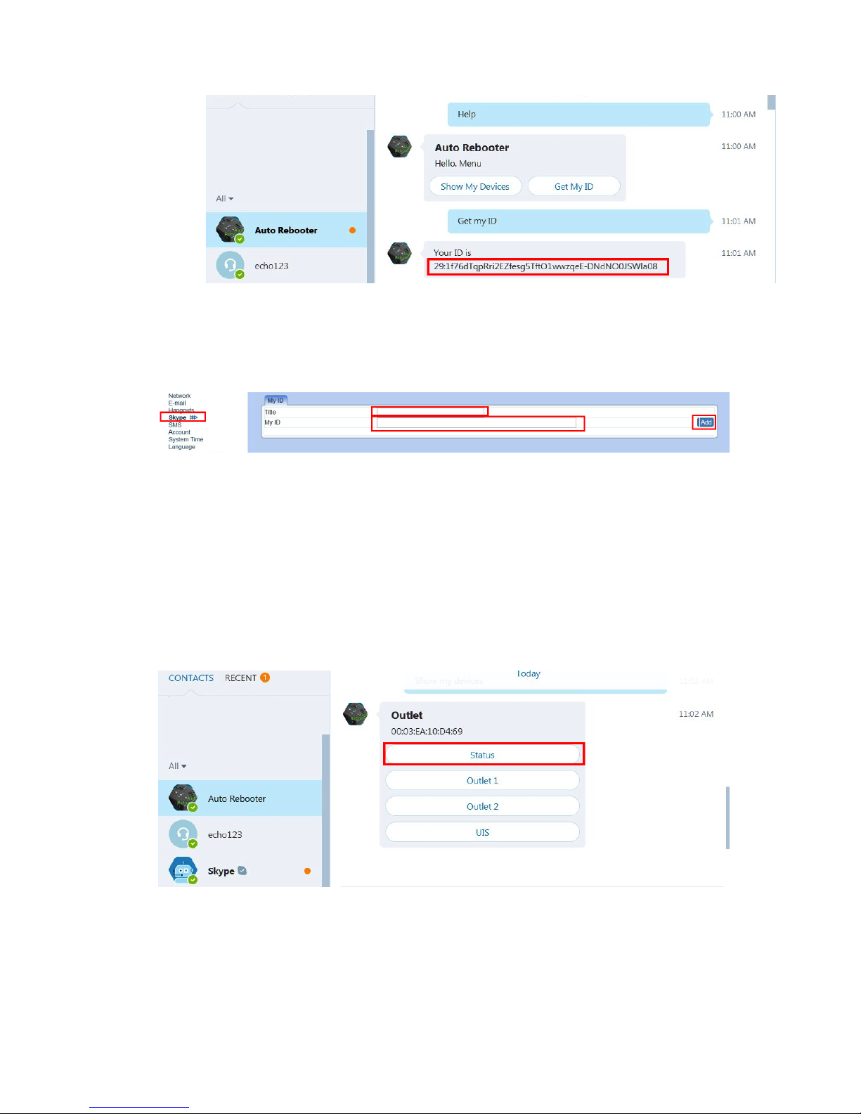
Step 5: Open The Skype App
1. Under the Contacts Section select Auto Rebooter
2. Type Help
3. Click Get My ID
4. Copy and Paste the ID
Page 17
17
5. Toggle back to the Admin Screen
6. Enter the Name for your Switch (any name you want to represent)
7. Paste the ID in the ID field
8. Click Add
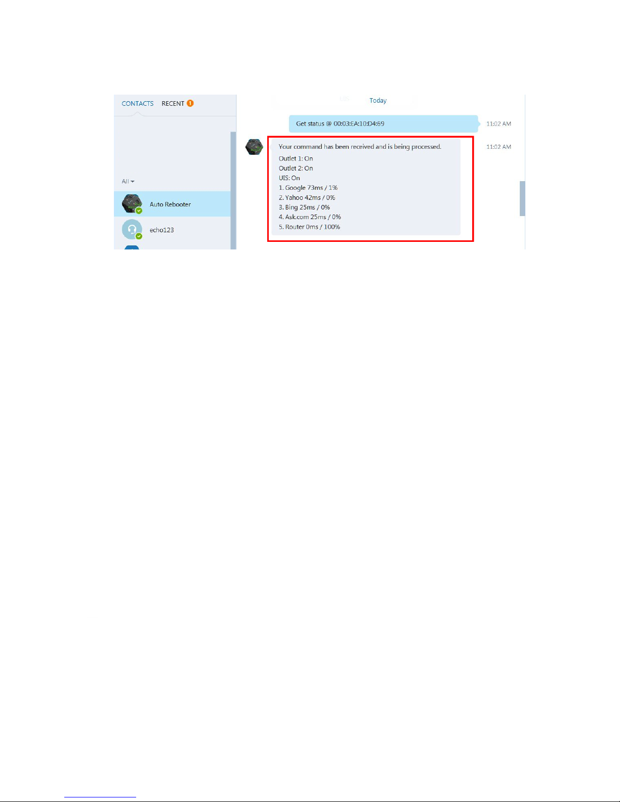
Step 6: Skype Control
1. Switch back to the Skype App
2. Click on Help then Show My Devices
3. Select the button that corresponds to the action you wish to perform
4. Example Status
5. Status will be displayed
Command example
Page 18
18
Result
Other Commands:
Outlet 1 or 2
Turn ON
Turn OFF
Reset
Back
UIS
Turn ON
Turn OFF
Back
Note*
If you have multiple outlets, just use the same ID (from Get My ID)
3.6. How to Upgrade/ Re-Flash Firmware
When issues occur with your IP switch, it is best to upgrade firmware (if available) or
re-flash the current version of firmware. This can be done with the Utility application
OR via the local web interface page. It can be accomplished with a computer that is
connected to the same network as the IP switch or, in certain cases when the IP
Switch is unreachable, you may connect it directly to your computer via the Ethernet
cable.
NOTE: Before performing the upgrade, it is recommended that your save your
settings. See section 4.4.1 for instructions on the Save/ Restore settings info.
Page 19
19
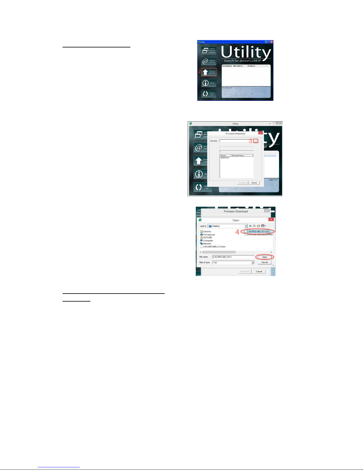
Upgrade Using Utility
Step 1: Launch the ‘Utility’ Windows
Application and let it detect IP switch.
Step 2: Click on the ‘Firmware
Upgrade’ button.
NOTE: If Utility cannot locate your
Switch please refer back to section
3.2.1
Step 3: In the dialog box that opens,
select the ‘…’ button to the right of
‘File Name.’
Step 4: Locate the firmware file and
open it.
Step 5: The file name should now
appear in the appropriate field. Now,
select the ‘Download’ button
Upgrade Using Local Web
Interface
Step 1: Log into the web user
interface of your IP Switch
Step 2: Navigate to the
Save/Upgrade section (on the left)
Step 3: Under the 'Upgrade
Firmware' section, click on the
'Browse'/ 'Choose File' button
beside 'Location'
Step 4: A window will open to view
your computer files. The firmware
typically saves to your downloads
Page 20

20
folder. Select the .bin file named and
click Open
Step 5: You'll now see the file appear
next to 'Location’ -> Click Apply to
begin the upgrade
NOTE: The firmware process takes
about 2-5 minutes.
Chapter 4: IP Switch Web User Interface
4.1. Information
The Information tab contains the following subsections:
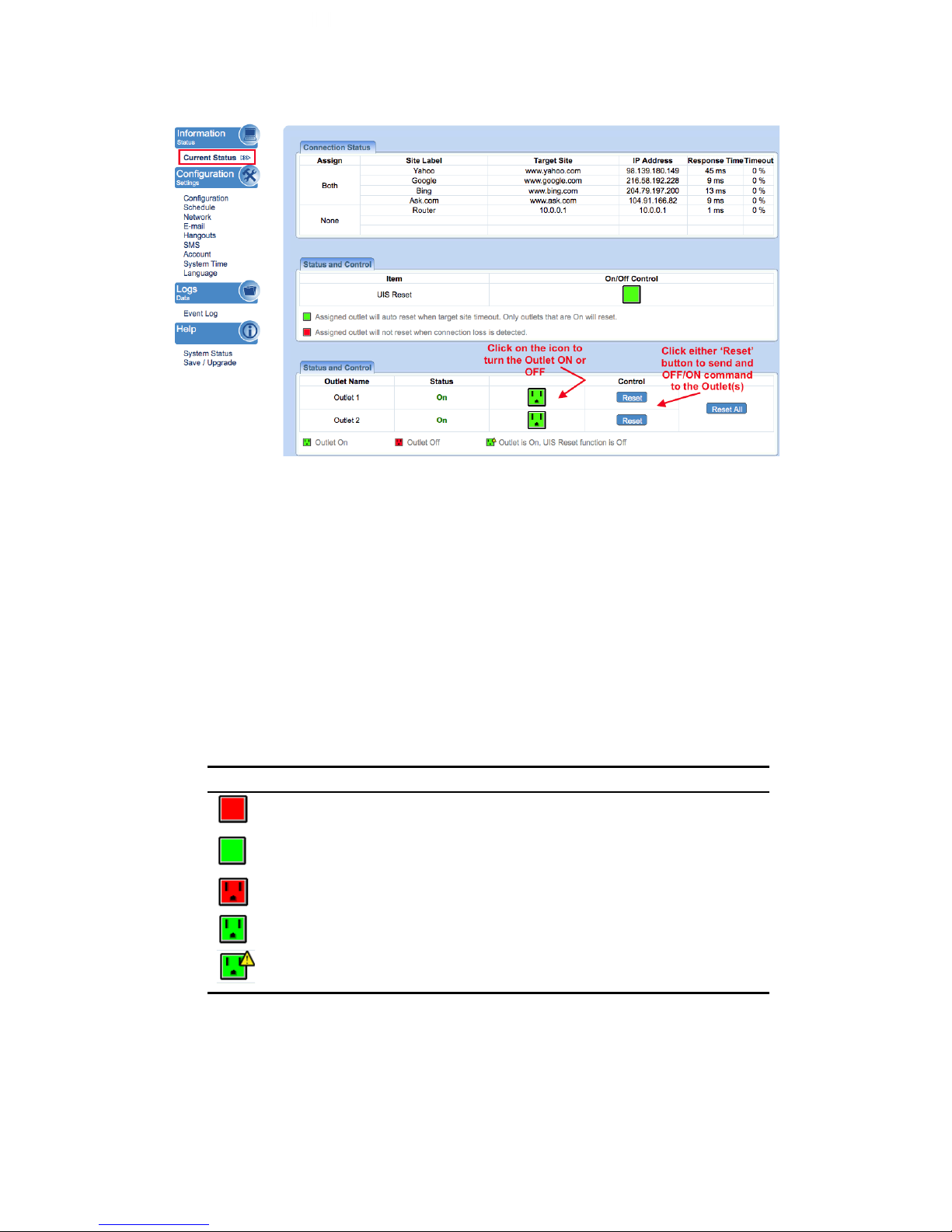
4.1.1 Current Status
4.1.1 Current Status
This section displays the current status of the outlets.
Page 21
21
Fig.7 Current Status page
i. Connection Status
Assign: This shows the outlets that are assigned to the target sites
Site Label: A name for the target site
Target Site: This is the default target site as listed under Configuration page
IP Address: The IP address of the Target Site
Response Time: based on UDP / TCP protocol sets in Configuration page
Timeout: Number of timeouts as a percentage of total tries since reset.
NOTE: This page will auto refresh every 5 seconds
ii. Status and Control
This section shows the current status of the UIS Function and Outlet. User can
click to control the Outlets or UIS function from here.
Icon
Description
The UIS Function is Off. IP Switch will not perform auto outlet
reset when connection loss is detected.
The UIS Function is On. IP Switch will perform auto outlet reset
when connection loss is detected.
The Outlet is Off
The Outlet is On
The Outlet is On, but UIS Function is Off. The outlet will not
auto reset.
4.2 Configuration
The following option allows the user to configure the IP Switch.
Page 22
22
4.2.1 Configuration
4.2.2 Schedule
4.2.3 Network
4.2.4 E-mail
4.2.5 Account
4.2.6 Google Talk/ Hangouts
4.2.7 System Time
4.2.8 Language
4.2.9 SMS
4.2.1 Configuration
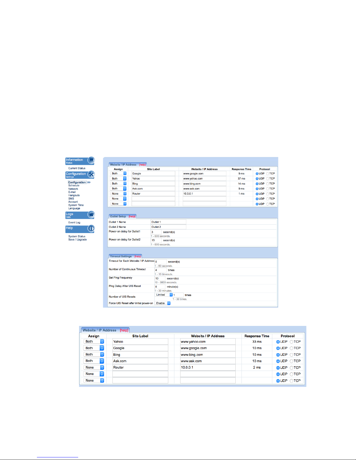
Use this section to configure how IP Switch checks websites. Advance users can
use this to customize IP Switch to check network devices.
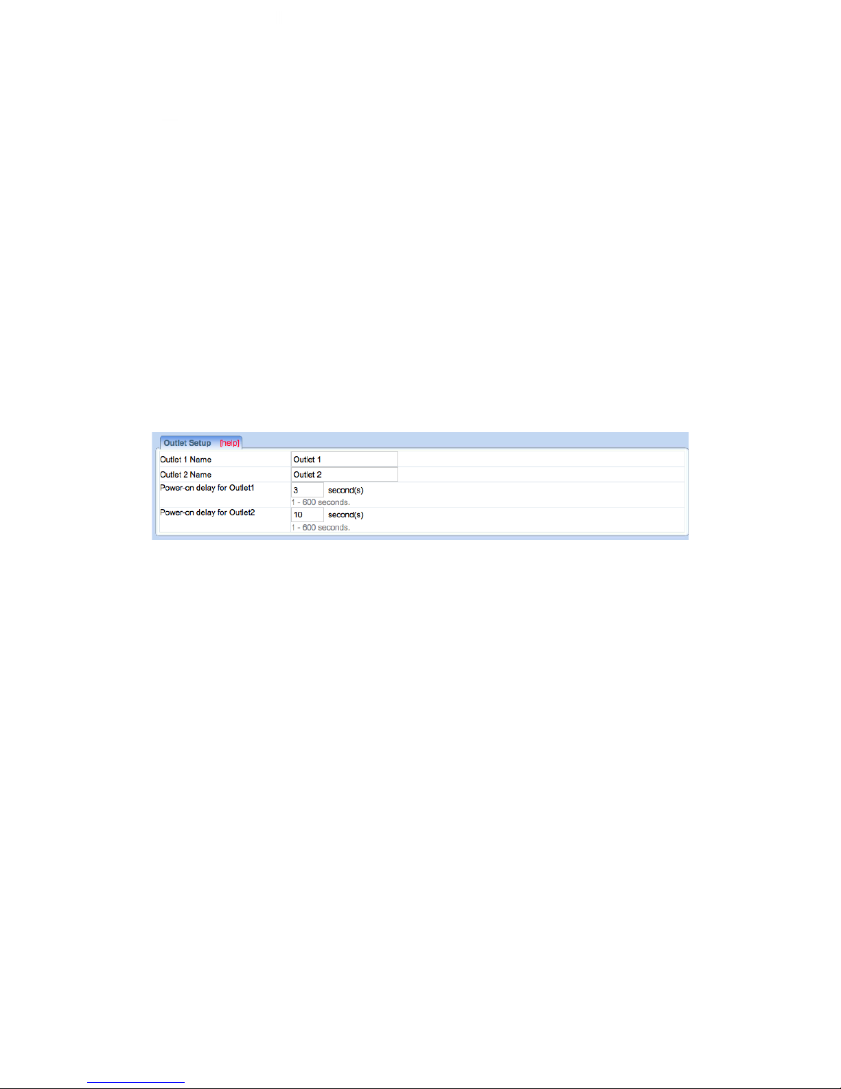
i. Website / IP Address
Assign:
Assign either one or both outlets to the website / IP address. Outlet assigned to
Page 23
23
a group of websites will auto reset, when all sites within that group timeout.
NOTE: Assignment cannot be for a combination of both and single outlets.
Site Label:
Give the IP address a short and easy to remember nickname. Max 16
characters.
Website / IP Address:
Enter a reliable website / IP address to ping.
Response Time:
The time it takes for a website to respond.
Protocol:
Select a suitable ping method for the website. Either a ping (UDP protocol) or a
web request (TCP protocol).
NOTE: The target site can be a Domain Name, IP Address or even LAN IP
Address – e.g. the router’s IP or local device on the router such as an IP
Camera.
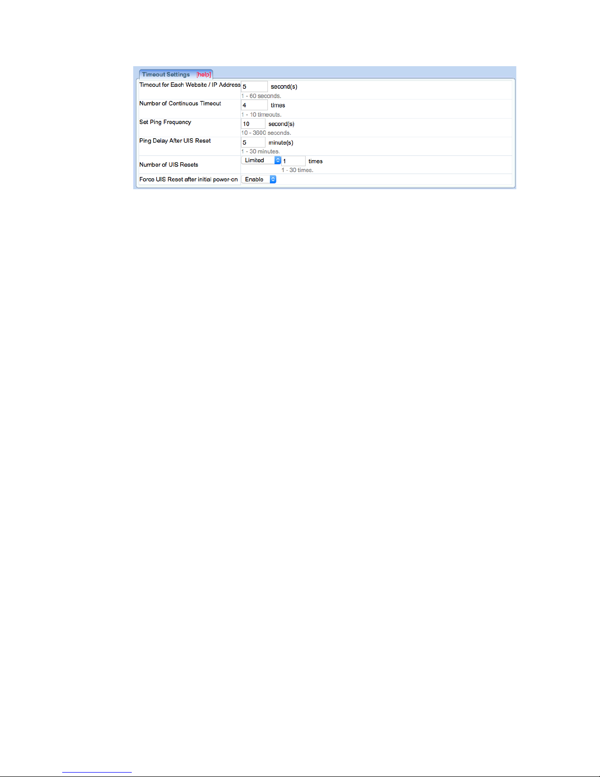
ii. Outlet Setup
Outlet 1/ 2 Name:
Give each outlet a name to easily identify the connected device (eg. router, modem,
etc).
Power-on Delay for Outlet 1:
Apply a delay (Power Off > Delay > Power On) to outlet #1’s power-cycle sequence.
Default is 3 seconds– configurable from 1-600 seconds.
Power-on Delay for Outlet 2:
Apply delay to Outlet 2, which takes place after Outlet 1 is reset. In default
configuration, Outlet 1 resets within 3 seconds and 13 seconds later, Outlet 2 resets.
Default 10 seconds – configurable from 1-600 seconds.
NOTE: Power Reset feature applies not only to the Reset here (Off > Delay >
On), but also to scheduled or manual resets. Only outlets that are currently
powered on will power cycle upon an auto reset.
iii. Time-out Settings
Page 24
24
Timeout for Each Website / IP Address
Assigned websites must respond within this time else, it timeout. Set a larger
value to allow for occasional internet lags. Default is 5 seconds.
NOTE: A larger timeout will allow for instances of delay or lag from target
sites.
Number of Continuous Timeout
Number of continuous failed responses from assigned websites before the UIS
reset is triggered. Default is 4 times.
Set Ping Frequency:
Administrator can set the website ping or connect interval (i.e. how frequently
the Switch pings the target sites). Default is 10 seconds.
Ping Delay After UIS Reset:
Set how long the Switch waits after a UIS reset BEFORE it starts checking for a
connection again.
Number of UIS Resets:
Set the number of UIS reset attempts when Internet connection is lost (e.g. If
set to 5 times - if connection is not restored after the 5th attempt, Switch will
wait in idle state until connection comes back).
Force UIS Reset after Initial power-on:
Force the outlets to reset if all target sites are unreachable after power-on (e.g.
Router boot failure after a power outage/ black-out. Resets only outlets that
were ON (before power off). UIS function MUST be enabled for this to work).
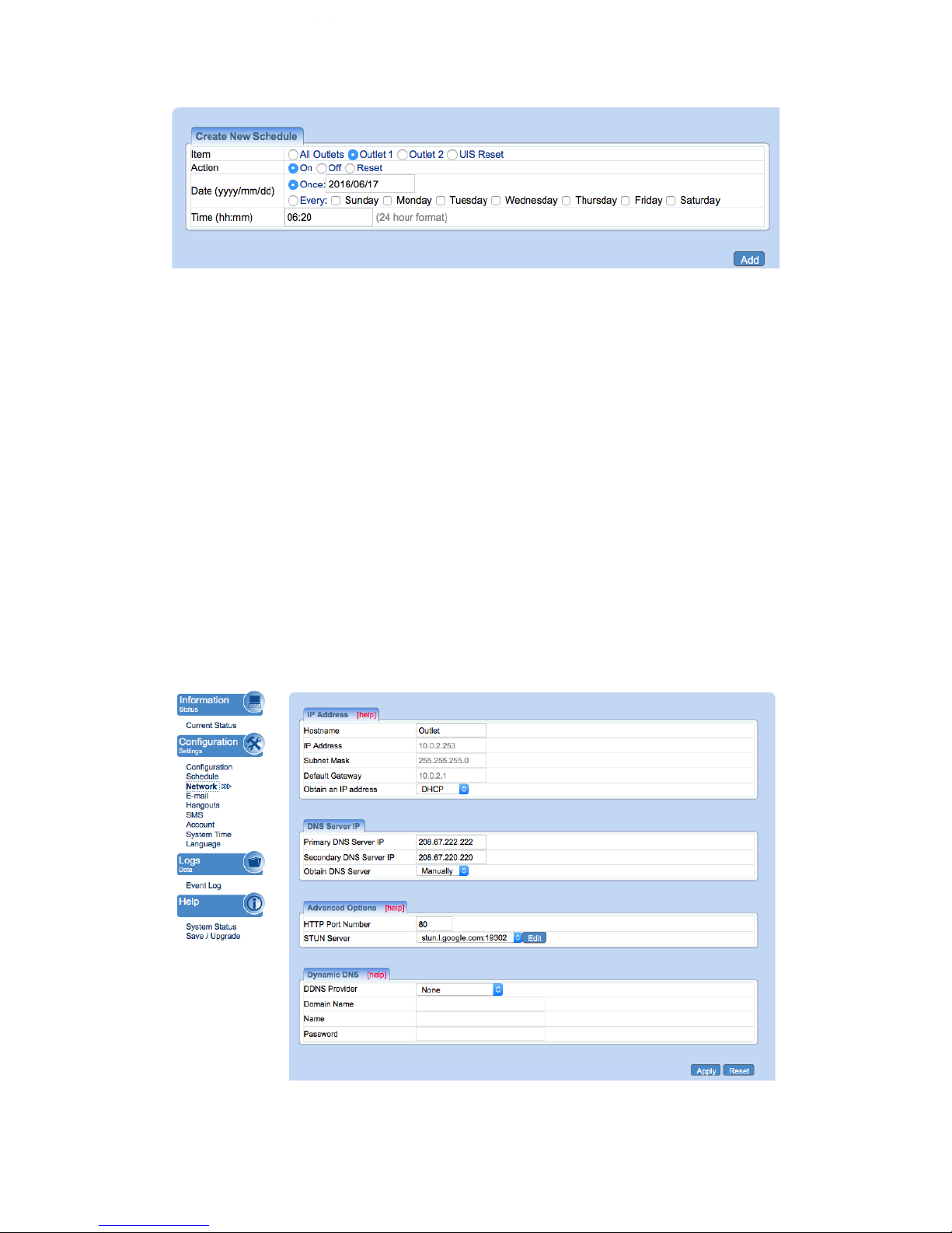
4.2.2 Schedule
This option allows the user to schedule the power on / off / reset for each of the two
outlets.
Page 25
25
i. New Schedule Event
Item
Select to schedule an event for either Outlet 1 or Outlet 2, Both, or UIS Reset.
Action
Select action to apply to above Outlets. To turn ON, OFF or RESET.
Date (yyyy/mm/dd)
Select the event frequency for the above outlet;
a. Once (the current date is automatically entered) or;
b. Reoccurring on a particular day, or a daily event.
Time (hh:mm)
Enter the time in 24hr format.
NOTE: A total of 20 schedules can be assigned. The scheduled events can be
edited, disabled, or deleted.
4.2.3 Network
This option allows the user to configure the IP address, port number and DDNS
functions.
Page 26
26
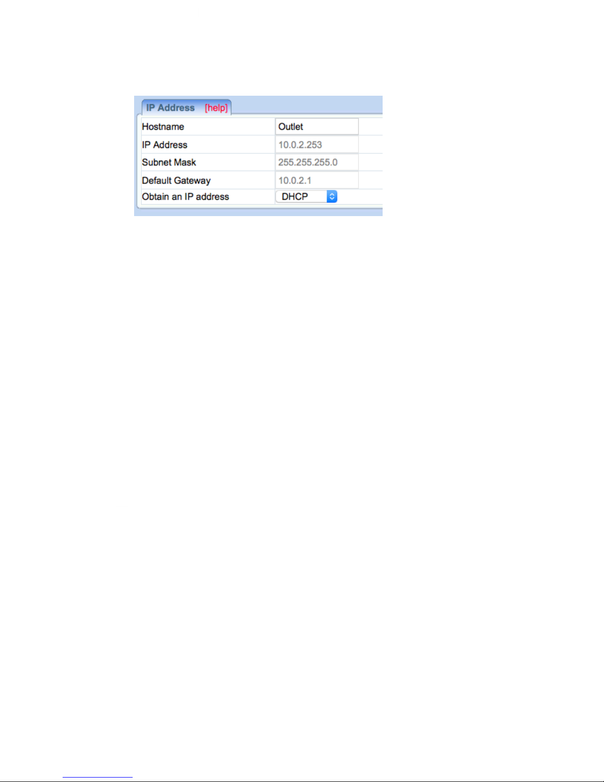
i. IP Address
Hostname
By default the hostname (LAN Domain Name) is set to Outlet. This should
allow the unit to be located on your router's client list when determining the LAN
IP address.
NOTE: If you have multiple IP Switch units, you should assign different
hostnames to each unit.
IP Address
This determines/ displays the IP Switch’s IP address. By default, the LAN IP
address assignment method is set to DHCP (IP address assigned by router).
TIP: We suggest changing this to a Fixed/ Static IP for ease of
management. You may so this by selecting ‘Manually’ rather than ‘Using
DHCP’ –OR, you can leave as DHCP and simply set a DHCP reservation
on your router so that the IP address does not change.
Subnet Mask
Displays IP Switch Subnet Mask.
Default Gateway
This sets the IP Switch Gateway IP address (this is the IP address of the router
the IP Switch is connected to).
More info at Appendix A: IP Address, Subnet and Gateway
Obtain an IP address
This allows the user to either manually set or use DHCP (default) function to
obtain the IP address from the router. Click Apply to save settings.
NOTE: Remote Power IP Switch will reboot when these settings are
changed.
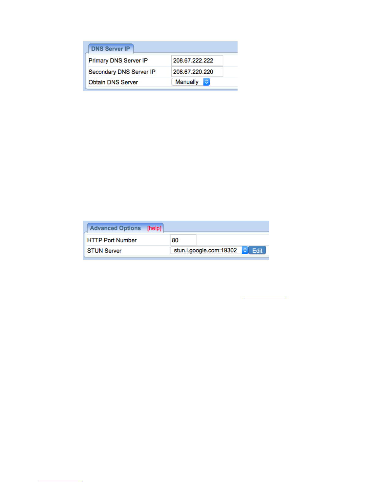
ii. DNS Server IP
Page 27
27
Primary DNS Server IP
The default IP Switch Primary DNS Server IP is 208.67.222.222. User can set
their preferred DNS server / one that is assigned by ISP.
Secondary DNS Server IP
Use this to set IP Switch Secondary DNS Server IP address. IP Switch will
use the Secondary DNS Server IP address if the Primary DNS Server IP
address is not working. Secondary DNS Server default IP is 208.67.220.220.
Obtain DNS Server
This allows the user to either manually set (default) or use AUTO function to
obtain the DNS servers from the router. Click Apply to save settings.
iii. Advanced Options
HTTP Port Number
This determines IP Switch user interface port. By default the LAN port number
is 80. If the port is changed, you will also need to change the manner in which
you access the switch via a web browser – i.e. If the port is changed to 82, then
to access IP Switch user interface, the user must type: http://x.x.x.x:82 (where
x.x.x.x is the IP Switch's LAN IP address as shown in Utility).
NOTE: Remote Power Switch will reboot when these settings are
changed.
STUN Server
STUN is a standardized network protocol to allow the device to discover its
public IP address when it is located behind a NAT. Disabling STUN will do the
following:
a. Prevent Google Talk “GET IP” command from returning the WAN IP
b. Email notification cannot show the current WAN IP
c. Dynamic DNS server cannot acquire WAN IP
Default is stun.I.google.com:19302
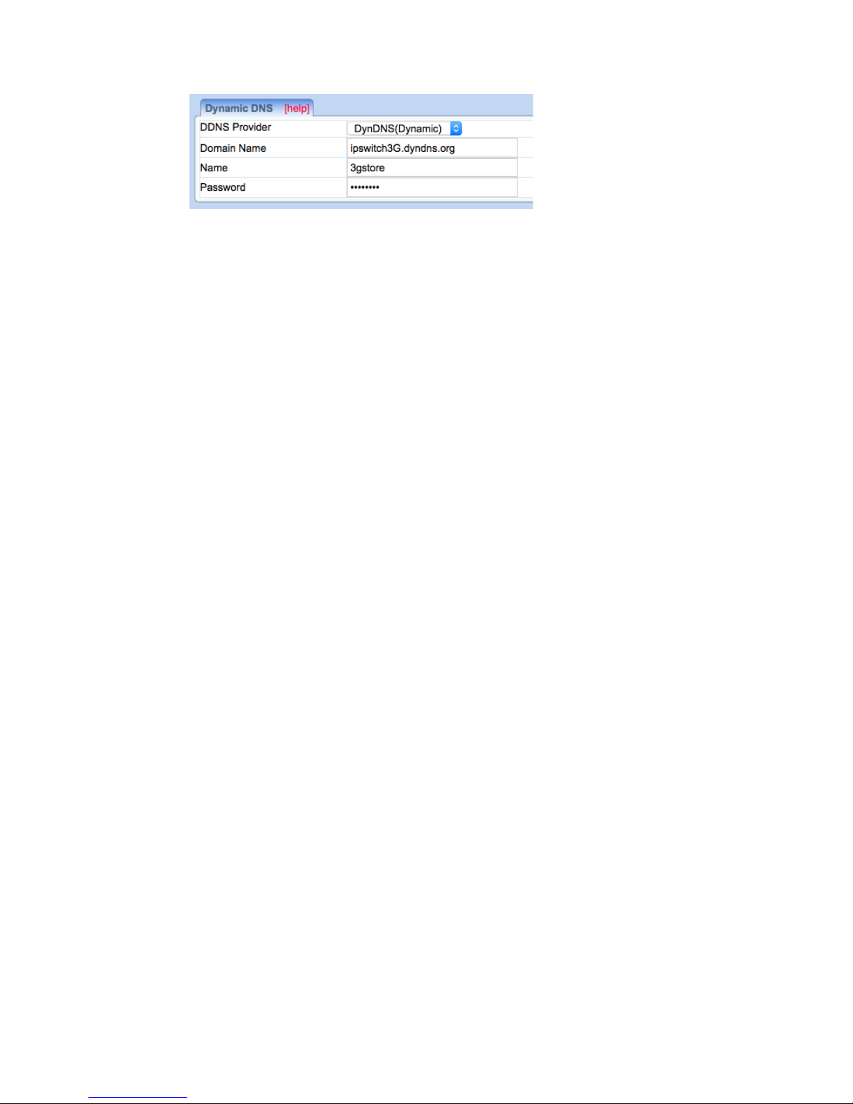
iv. Dynamic DNS
Page 28
28
Dynamic DNS (“DDNS”) is a third party service – some providers offer free
service, others require a fee. It allows the user to alias a dynamic WAN IP
address to a WAN hostname. So no matter how many times your ISP changes
the IP address, you will be able to locate your unit over WAN using your DDNS
hostname.
DDNS providers include:
● 3322.org
● dhs.org
● DynDNS (Dynamic)
● DynDNS (Custom)
● myDDNS.com
● Zive.org
In general, to register a Domain Name with one of these sites;
a. Go to the DDNS provider website listed above.
b. Register a new user account and password with the DDNS provider.
c. Choose a Domain Name to point to your current Dynamic IP
d. Enter information obtained in (b) and (c) into the corresponding DDNS
fields in IP Switch.
Domain Name
This is the Domain Name you have created from the above selected DDNS
provider.
Name
This is the Login / Account name that you have created with the selected DDNS
provider.
Password
Enter the Password you have assigned to your DDNS Account.
4.2.4 E-mail
This function will send event notifications to email accounts listed in the ‘E-mail
Address Book’. Events are also logged in “Event Log” section.
Page 29
29
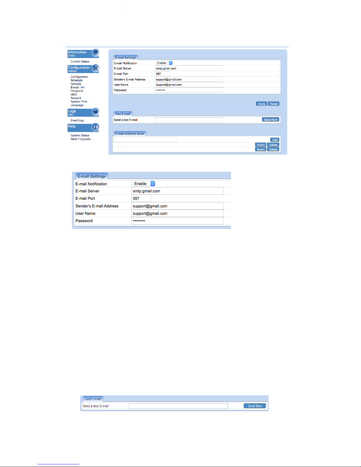
i. E-mail Settings
E-mail Notification
When ‘Enabled’ and settings are applied, user can receive notifications form
the Switch. 2 additional sections will appear that also must be configured –
‘Test E-mail’ and ‘E-mail Address Book’
E-mail Server
Only SMTP servers are supported. IMAP & HTTP mail servers are not
supported. Example: smtp.gmail.com
E-mail Port
Default is port 25. User can specify a different port if necessary. *Port 465 and
587 is frequently used.
Sender’s E-mail Address
Enter the full E-mail address assigned by your e-mail server.
User Name / Password
Enter your full E-mail Address and the password associated with it.
NOTE: If you are using Google 2-step Authentication see Page 45 for
additional configuration steps.
ii. Test E-mail
Page 30
30
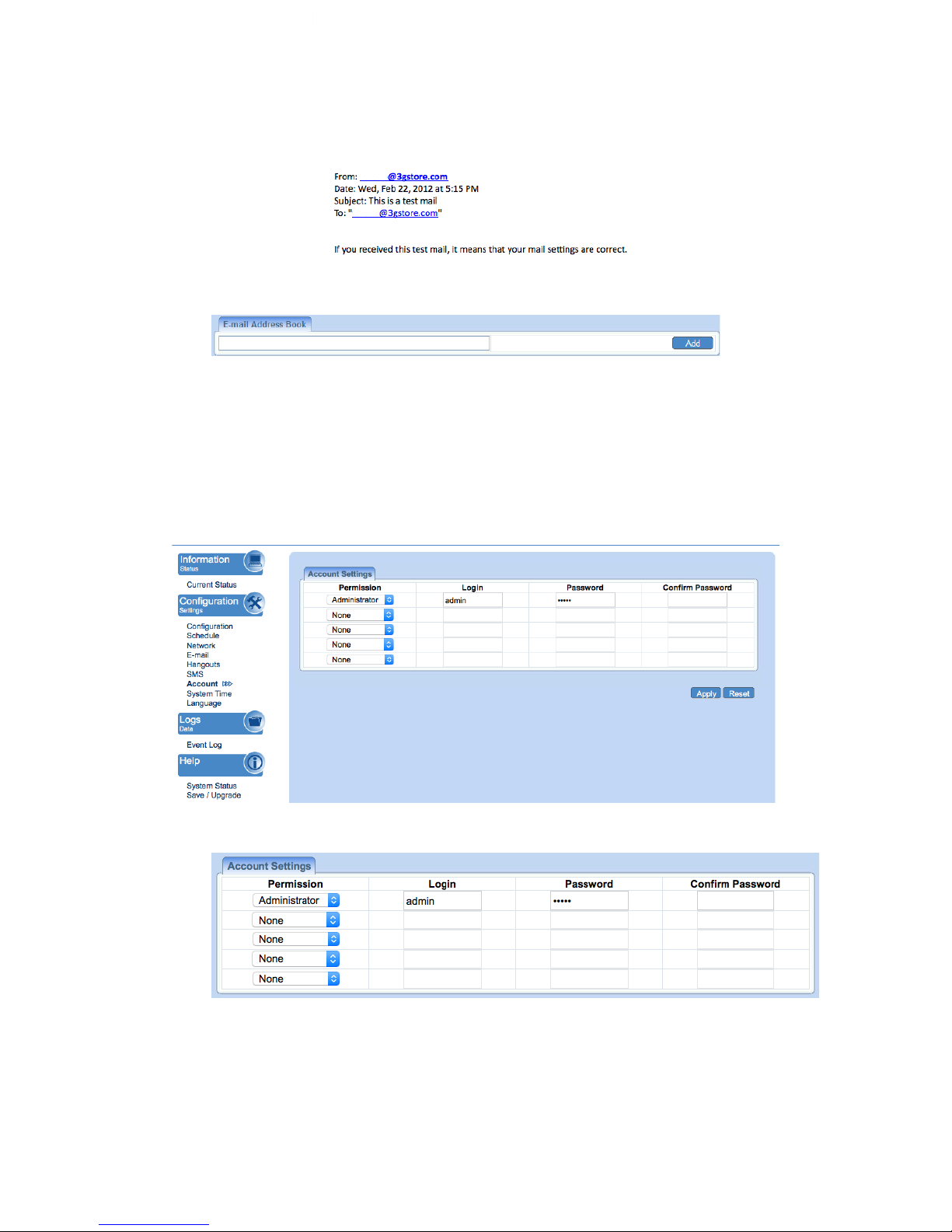
Send a test E-mail
Enter a valid e-mail address to send the test email to. Example of email
received:
iii. E-mail Address Book
E-mail Address Book
List the users who shall receive an e-mail notification, as they appear in the
Event Log section.
4.2.5 Account
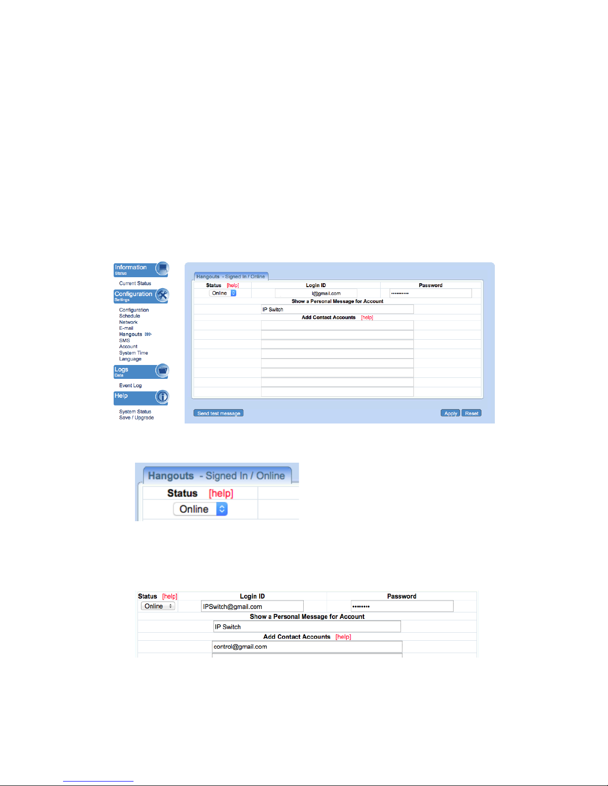
This webpage allows you to set an administrator password. You may also set up a
‘viewer’ account. A viewer account may view the settings, but cannot make changes.
A maximum of 5 user accounts can be configured.
i. Account Settings
Permission
Page 31
31
Administrator account is set up by default. Viewer account can be configured
if users want to allow others to view the settings without being able to make any
changes.
Login
The administrator can set a name consisting up to 32 case sensitive characters.
By default the Administrator Login and Password are both admin / admin.
Password / Confirm Password
Assign a password to the account. The administrator can set up to a 32 case
sensitive password. Enter it a 2nd time to confirm password.
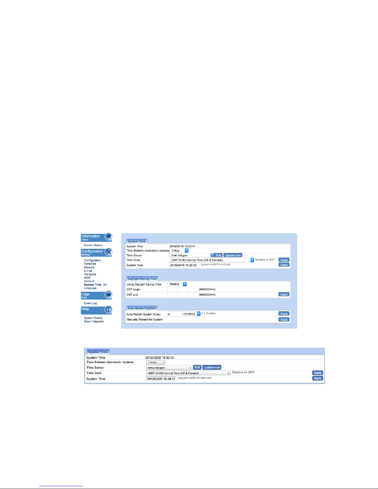
4.2.6 Hangouts (Previously called Google Talk)
Setup IP Switch to be controllable via Google Hangouts.
Fig.8 Hangouts Settings page
i. Hangouts
Status
This determines the status of the IP Switch’s Gmail account. Select either
‘Offline’ or ‘Online’ - See the tab labeled “Hangouts” above
Login ID
Page 32
32
Enter the Login ID that you have created from the Gmail website for the IP
Switch.
Password
Enter the corresponding password with the above account.
Show a Personal Message for Account
Enter a message here. This message will be visible to anyone that is in the IP
Switch’s Hangouts contact list.
Add Contact Accounts (to access / control the above account)
The administrator can assign up to 8 Gmail users who can receive notification,
control AND receive IP Switch feedback from their Gmail account. Once
assigned, the respective user must then ‘add/invite’ the IP Switch to their
Contact list - this chat invitation is generated once the Administrator clicks
‘Send Test Message’. Failing to accept the chat invitiation will result in the
user not being able to communicate with the IP Switch. Once the contact is
added, just type a random character and IP Switch will respond with
instructions. Refer to section 3.4.2 above on how to use Hangouts.
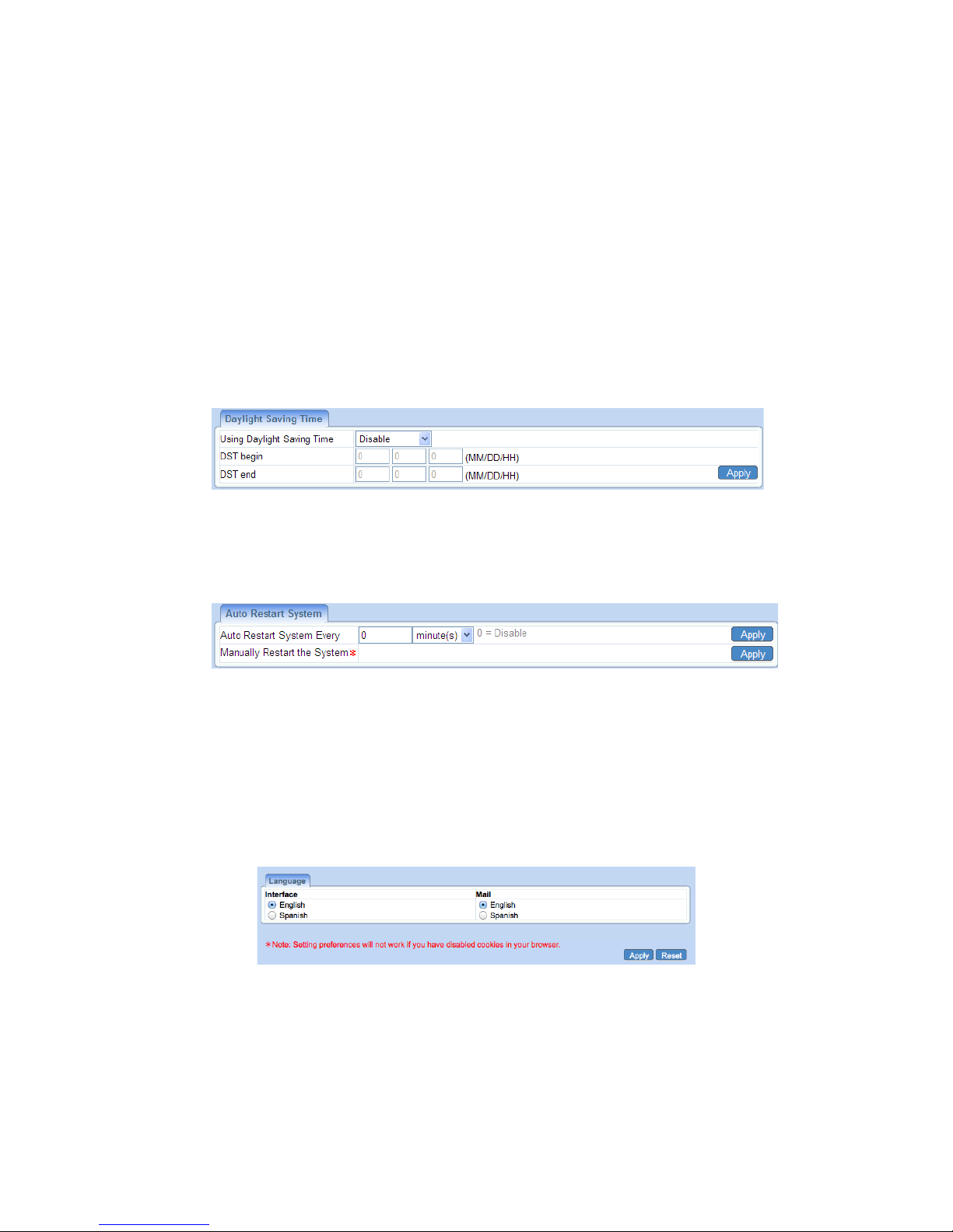
4.2.7 System Time
Use to set the time zone, apply daylight savings start/end, and configure the system
for automatic restarts.
Fig.9 System Time Settings page
i. System Time
System Time (yyyy/mm/dd hh:mm:ss)
This section is to manually set the IP Switch System Time. The format is pre-
determined to: yyyy/mm/dd hh:mm:ss (in 24hr format). Click Apply to save the
changes.
Page 33
33
Time Between Automatic Updates
The user can set an interval for time synchronization. Select from either; none,
1, 3, 12 hours or 1, 10 & 30 days. Default is 1 Hour.
Time Server
Choose the nearest Time Server to your location. The user can choose from
the list of a maximum of 30 Time Servers. To add a new Time Server, click
Edit, delete an existing Time Servers from the list, then, the Add dialog box
will appear. Click Back to return to the System Time Settings webpage.
Time Zone (Relative to GMT)
Select the appropriate time zone. Click Apply to save changes.
ii. Daylight Saving Time
Using Daylight Saving Time
Disabled by default. Administrator can configure it to AUTO obtain Daylight
Saving Time info OR Manually enter the DST begin and DST end dates.
iii. Auto Restart System
Auto Restart System every XX minutes/ hours… (0 = Disabled)
Set the IP Switch server to automatically restart after a pre-set interval. This
will reset the server. The power supply to each individual outlet is not disrupted
during the server restart process. Use this to guard against system freeze.
Manually restart the system
Click Apply to manually restart the system immediately.
4.2.8 Language
Use this section is to set the language interface.
i. Language
Choose the language for the Web UI and E-mails.
4.2.9 SMS
Page 34
34
*This feature is NOT supported at this time.
4.3 Log Information
4.3.1 Event Log
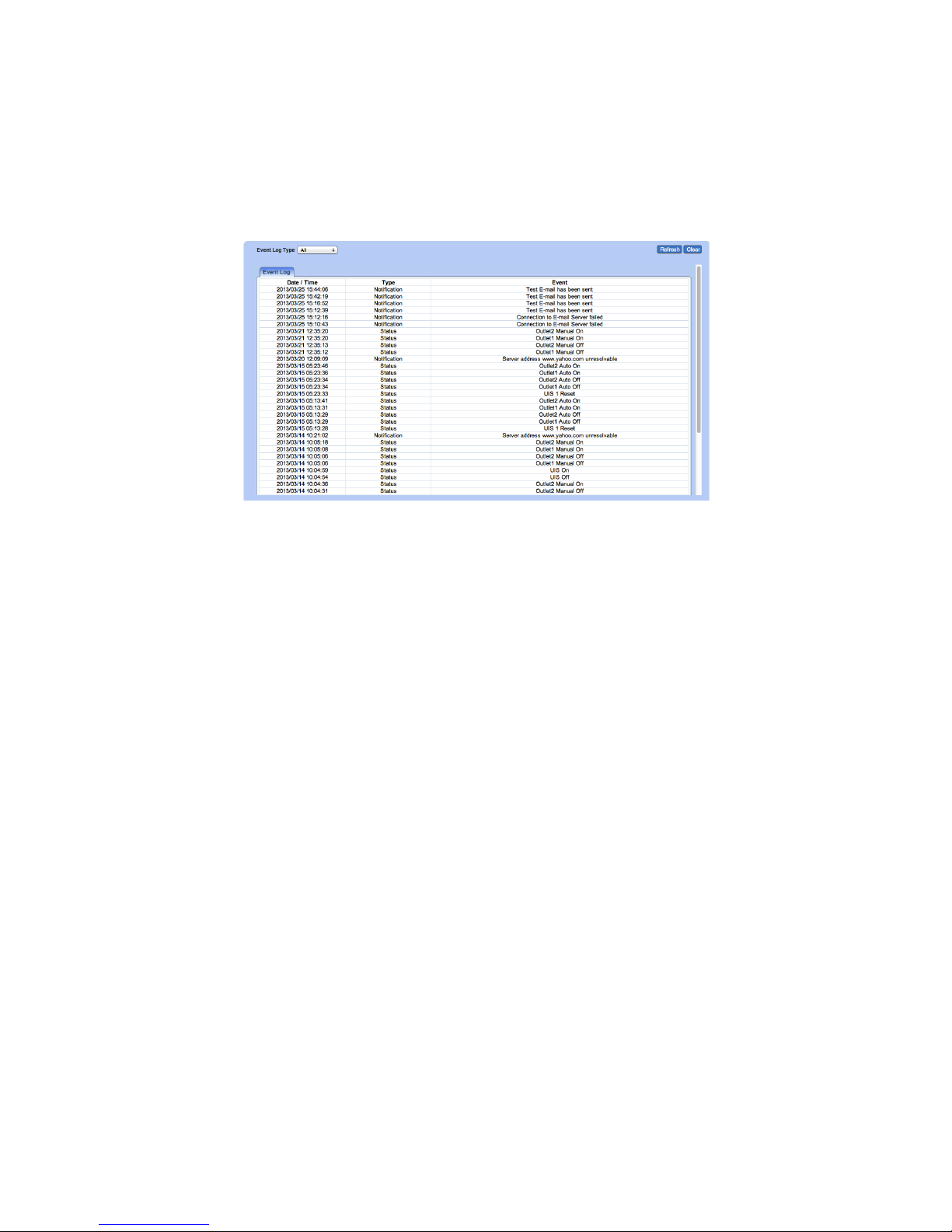
This section will log events that occurred on the IP Switch and categorize them.
Fig.10 Event Log
Event Log Type
Select which type of log to show:
a. All (both Status and Notifications are shown)
b. Status
Examples of Status logs:
UIS On/Off, Outlet Manual On/Off, Outlet Auto On/Off, UIS 1/2 resets
c. Notification
Examples of Notification logs:
Server address ‘xxx’ is unresolvable, Test email sent, Connection to Email
server failed
NOTE: If the System Time is not set up correctly, the event log may
display a generic ‘2000/01/01’ in the Date/ Time area. Once the System
Time is synchronized, it will update all the Event Log times.
4.4 Help
4.4.1 System Status
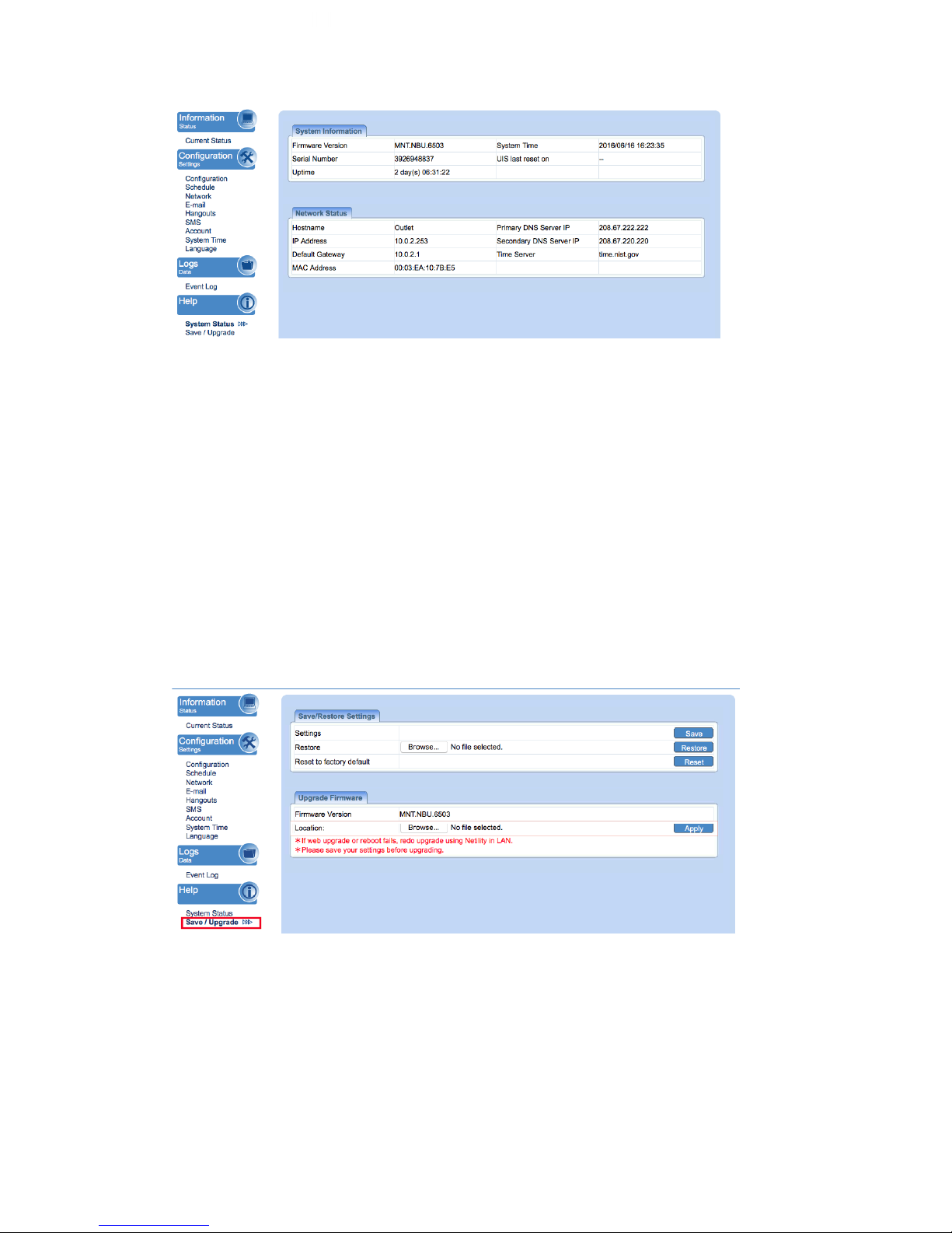
This webpage displays System Status Information.
Page 35
35
i. System Information
This section shows general hardware information such as the Hardware and
Firmware Version, the serial number, Uptime, System Time and when the
system last reset.
ii. Network Status
This section shows all information relating to the Network environment.
Hostname
This is the default hostname. User can rename this by browsing to
Configuration → Network page.
4.4.2 Save / Upgrade
The administrator can use this section to check firmware information, save/restore
settings, and see manufacturer’s details.
Fig.11 About page
i. Save / Restore Settings
Settings
Click Save to save the configuration to your PC. The text file will have a default
format of SettingsYYYYMMDD.cfg.
Page 36

36
Restore
Use this function to restore a *.cfg configuration that has been saved earlier.
Click Browse… and locate the file you saved. Click Restore.
Reset to factory default
This function will reset all settings to its default configuration.
ii. Upgrade Firmware
Firmware Version
Displays the current firmware version running on the Switch.
Location
This is where you would will select a firmware file to upgrade/ flash to the
Switch.
Page 37

37
Chapter 5: Troubleshooting Tips
1. Assign a static IP (manual) address to the Power Switch rather than using
DHCP.
a. Like with most LAN connected, remote devices this is a more
stable/reliable way of connecting the Switch to your network
b. To configure this, we recommend using the Utility program:
i. Open Utility and search for the Switch (click ‘refresh list’ if not
appearing) – NOTE: If it does NOT appear, make sure that you
are connected to the same physical LAN. This will not work if
you are connecting through a VPN. Having anti-virus software
of restricted admin privileges on the computer may also
prevent Utility from locating the Switch.
ii. Once found, select the ‘Network Settings’ button. A window
will open.
iii. In the IP address tab select ‘Use the Following Static IP
address.’ Enter an IP address within the same subnet to your
PC. Example: If your router’s default LAN/gateway IP is
192.168.0.1, you can use an IP address of: 192.168.0.10 (or
something outside the DHCP range) and subnet mask of
255.255.255.0. Gateway will then be 192.168.0.1
iv. Click OK to apply.
2. Ensure the UIS function is enabled and Internet light is illuminated.
Without UIS enabled, the Switch will not know to monitor the connection.
You also need to make sure the Switch is receiving an Internet connection,
or else it won’t be able to ping web addresses to monitor the connection
3. Check your Configuration settings. Specifically, the ‘Timeout Settings’ &
‘Outlet Setup.’ For users who have a separate modem and router plugged
into each port: Typically, you want the modem to power up completely and
connect to the Internet prior to the router powering on. We normally
recommend at least 1 minute in between these. *SEE: ‘Ping Delay After UIS
reset’ AND ‘Power-on delay for Outlet 1/ Outlet 2.’
a. Also, to avoid too many timeouts due to a slow Internet connection,
you may want to adjust Timeout Settings to a higher interval than
default. In most cases, you’ll need to experiment with settings to see
what works best.
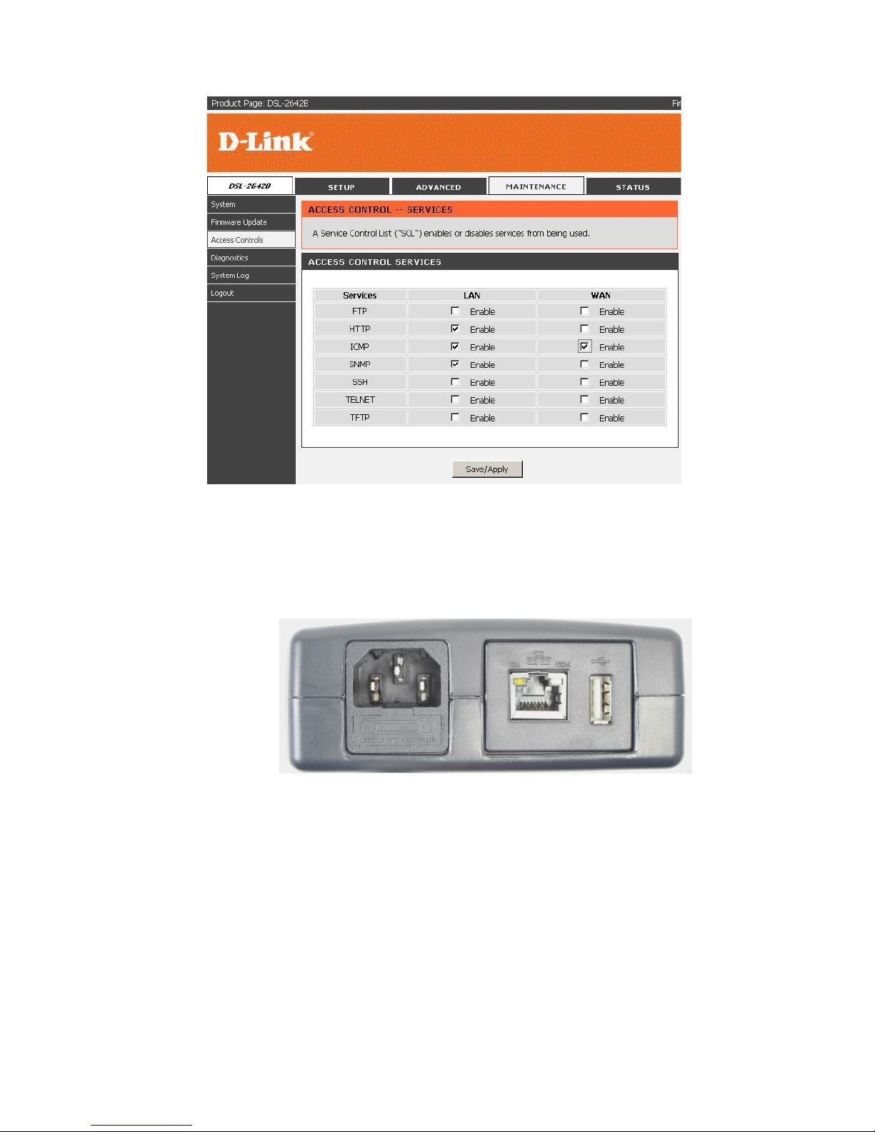
4. Check your router for a setting such as: ‘Block ICMP Ping’ OR ‘Block
WAN ICMP Ping’ (see example screenshot below).#Most routers from ISPs
have built in firewalls, meant to protect from malicious activity and outside
intrusion, but these built in firewalls can also block devices from functioning
properly when connected to the network. A common feature, "Block ICMP
Ping", is typically set to 'Enable,' meaning the router will block the response
back to the IP Switch. This means the switch can never properly manage
your Internet connection. Depending on your router, this feature can be
found in different places, and take a variety of different names. 3Gstore
doesn't provide support for 3rd party routers, however you can contact the
ISP or manufacturer for this setting. For most users, the IP Switch works just
fine with no extra configuration required.#
Page 38
38
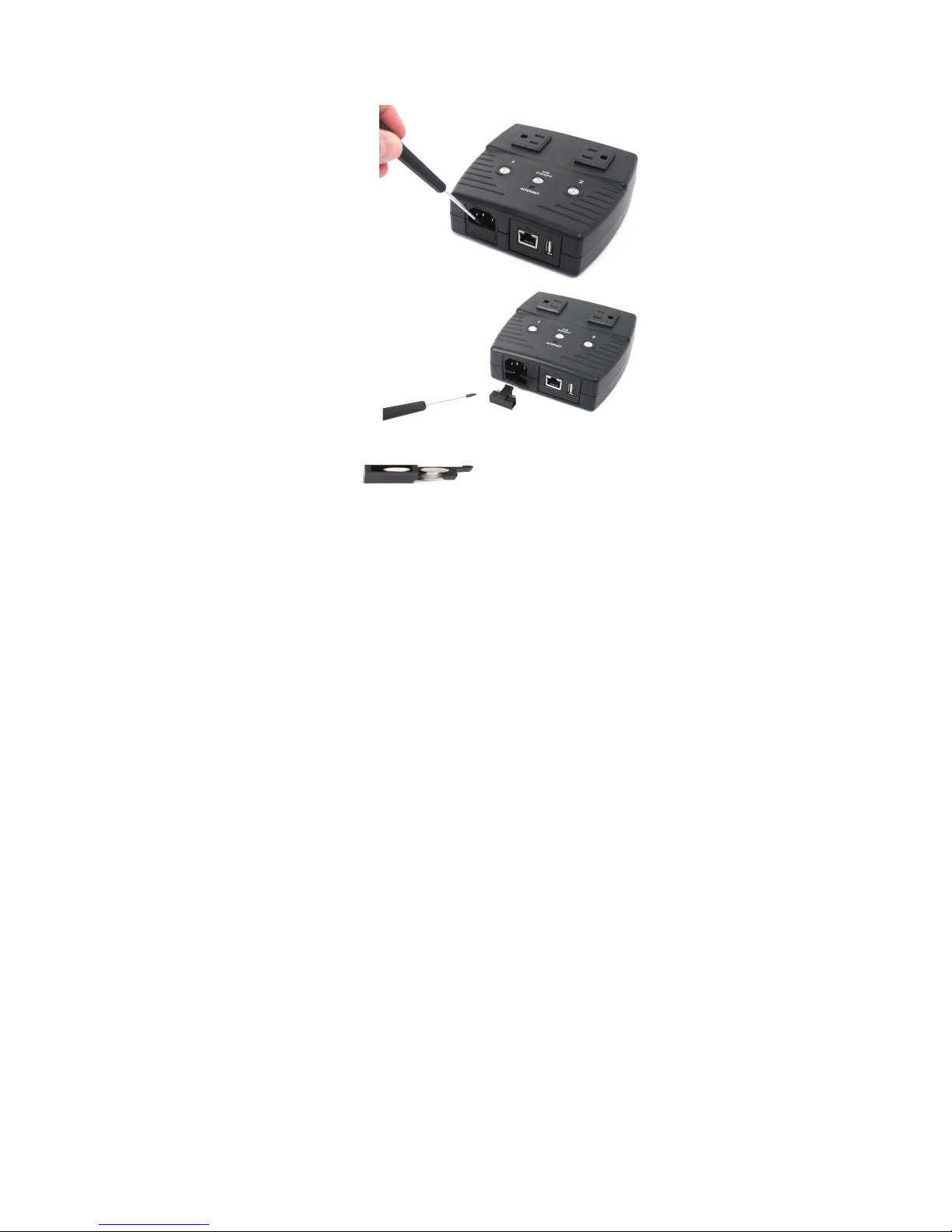
5. Check the Fuse: If your IP Switch is not powering ON, it’s possible the fuse
may be bad. Follow the steps below to change out the fuse with the back up
a. Remove the Power Cord and Ethernet Cable from your IP Switch
before proceeding. Locate the Fuse Door just under where the
power cord attaches.
b. With a flat tipped screwdriver, carefully remove the fuse door by
pulling away from the IP Switch.
Page 39
39
c. With the Fuse Door removed, swap the main fuse with the backup.
(Left - Backup, Right - Main)
d. Return the Fuse Door to the IP Switch, making sure it sits flush
with the surrounding surface. Reconnect the Power Cord and
Ethernet Cable.
6. FOR TESTING: In order to simulate an outage [to make sure the Switch is
resetting properly], unplug the Ethernet cable from the WAN port of your
router. OR, if you have an all-in-one modem/router, unplug the cable that’s
connecting your cable or DSL line to the modem/router. If you simply remove
the LAN cable from the Switch itself, it will loose LAN connectivity and
without that, the Switch has nothing to monitor and therefore will do nothing.
Page 40

40
Appendix A: Router Configuration
The following section describes the initial configuration of the router and port
forwarding for your router. If your router is not listed here, please refer to the
manufacturer’s website for assistance with configuring your router to work with IP
Switch.
Port Forwarding for IP Switch
IP Switch requires certain ports to be open on your router to allow other computers
on the Internet to view it on your internal network. Normally, your router will have the
less common ports disabled or blocked by the router’s built-in firewall. In order for IP
Switch applications to work properly and not be blocked, the firewall settings need to
be configured. In each instance there will be a trigger port and incoming port(s),
where traffic on the trigger port tells the Firewall to open the incoming ports. IP
Switch requires that TCP Port 80 (default settings) be opened to the Internet. TCP
Port 80 is used for accessing the IP Switch homepage.
Change to other port if your Internet service Provider blocks port 80.
Below are some examples of setups, you should refer to your Router’s User manual
or contact your router manufacturer for assistance in configuring the router.
D-Link (http://www.dlink.com)
DI-604/DI – 614+/DI-624
1. Log into your router using your router IP.
2. On the main page, click on Advanced at the top of the page.
3. On the left side of the page, click on Virtual Server. Note: Make sure DMZ host is
disabled. If DMZ is enabled, it will disable all Virtual Server entries.
4. Enter the following information on the page:
Enable/Disable:
Enabled
Name:
IP Switch - Webpage
Private IP:
Type in the UIS LAN IP address, for example: 192.168.0.5
Protocol Type:
TCP
Private Port:
80
Public Port:
80
Schedule:
Always
5. Click Apply to save the settings. IP Switch should now be configured to work with
your router and be accessible from the Internet.
Page 41

41
DI-704/704P
1. Log into your router using your router IP.
2. On the main page, click on Advanced at the top of the page.
3. On the Virtual Server page, enter the following information:
For ID#1:
Service Port:
80
Service IP:
Type in the IP Switch IP address, for example: 192.168.0.5
Enabled/Disabled:
Enabled
4. Save your settings. IP Switch should now be configured to work with your router
and be accessible from the Internet.
Dell (http://www.dell.com)
TrueMobile 2300 Wireless Broadband Router
1. Log into your router using your router IP.
2. On the main page, click on Advanced Settings at the top of the page.
3. Go to the Port Forwarding section and select Custom Port Forwarding Settings.
4. Check the Enable box.
5. Enter the desired name or description in the Service Name field such as IP
Switch Web.
6. In the Incoming Ports field, specify port 80 in both boxes.
7. In the Destination IP Address field, enter IP Switch LAN IP address.
8. In the Destination MAC Address field, enter IP Switch MAC address. You can
find the camera’s MAC address by either looking at the MAC address sticker on the
bottom of the camera or by utilizing setup utility to display the MAC address.
Microsoft (http://www.microsoft.com/hardware/broadbandnetworking)
Page 42

42
MN-100 – Wired Base Station
MN-500 – Wireless Base Station
1. Log into your router using your router IP.
2. Open the Bass Station Management Tool, and then click Security.
3. On the Security menu, click Port Forwarding, and then click Set up persistent
port forwarding.
4. In the Enable checkbox, check in the checkbox.
5. In the Description box, type a description of the server field such as: IP Switch
Web.
6. In the Inbound port boxes, type in: 80 – 80. (i.e. from Port 80 to Port 80)
7. In the Type box, select the protocol as TCP.
8. In the Private IP address box, type in the IP Address of IP Switch network. For
example, type in: 192.168.0.5.
9. In the Private port boxes, these values are automatically filled in from Step 6 and
should already show 80 – 80.
11. Click Apply to save the changes you have made. IP Switch should now be
configured to work with your router and be accessible from the internet.
Appendix B: IP Address, Subnet and Gateway
This section discusses Gateways, IP Addresses and Subnet masking
Gateways
Gateway, also referred to as a router, is any computer with two or more network
adapters connecting to different physical networks. Gateways allow for transmission
of IP packets among networks on an Internet.
IP Addresses
Every device on an Internet must be assigned a unique IP (Internet Protocol)
address. An IP address is a 32-bit value comprised of a network ID and a host ID.
The network ID identifies the logical network to which a particular device belongs.
The host ID identifies the particular device within the logical network. IP addresses
distinguish devices on an Internet from one another so that IP packets are properly
Page 43
43
transmitted.
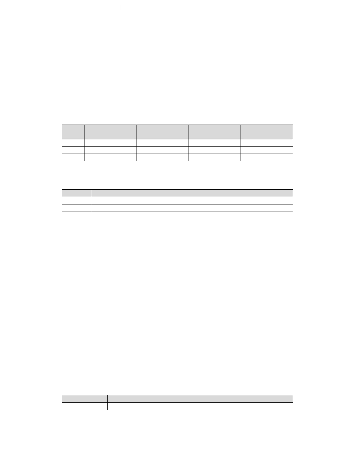
IP addresses appear in dotted decimal (rather than in binary) notation. Dotted
decimal notation divides the 32-bit value into four 8-bit groups, or octets, and
separates each octet with a period. For example, 199.217.132.1 is an IP address in
dotted decimal notation.
To accommodate networks of different sizes, the IP address has three divisions –
Classes A for large, B for medium and C for small. The difference among the
network classes is the number of octets reserved for the network ID and the number
of octets reserved for the host ID.
Class
Value of First
Octet
Network ID
Host ID
Number of
Hosts
A
1-126
First octet
Last three octets
16,387,064
B
128-191
First two octets
Last two octets
64,516
C
192-223
First tree octets
Last octet
254
Any value between 0 and 255 is valid as a host ID octet except for those values the
InterNIC reserves for other purposes
Value
Purpose
0, 255
Subnet masking
127
Loopback testing and interprocess communication on local devices
224-254
IGMP multicast and other special protocols.
Subnetting and Subnet Masks
Subnetting divides a network address into sub-network addresses to accommodate
more than one physical network on a logical network.
For example:
A Class B company has 100 LANs (Local Area Networks) with 100 to 200 nodes on
each LAN. To classify the nodes by its LANs on one main network, this company
segments the network address into 100 sub-network addresses. If the Class B
network address is 150.1.x.x, the address can be segmented further from 150.1.1.x
through 150.1.100.x
A subnet mask is a 32-bit value that distinguishes the network ID from the host ID for
different sub-networks on the same logical network. Like IP addresses, subnet
masks consist of four octets in dotted decimal notation. You can use subnet masks
to route and filter the transmission of IP packets among your sub-networks. The
value “255” is assigned to octets that belong to the network ID, and the value “0” is
assigned to octets that belong to the host ID.
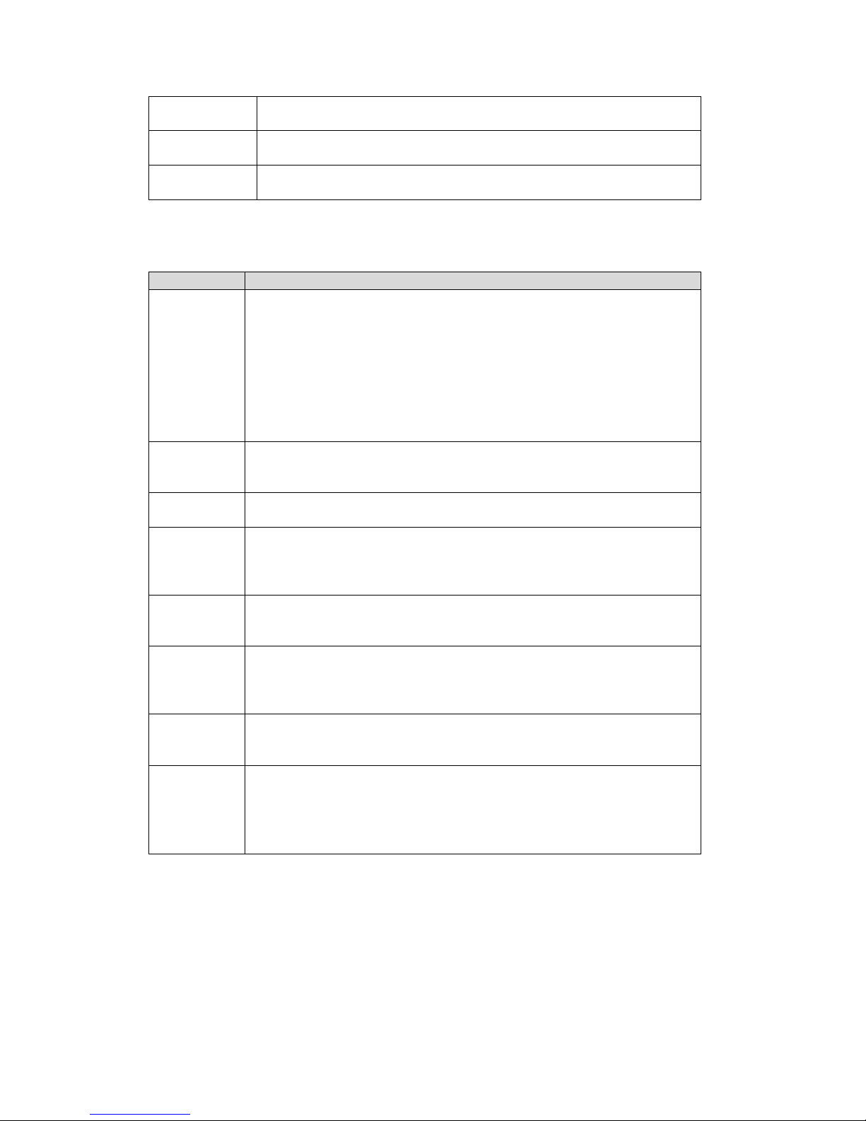
For the example above, if you want all the devices on the sub-networks to receive
each other’s IP packets, set the subnet mask to 255.255.0.0. If you want the devices
on a single sub-network only to receive IP packets from other devices on its own subnetwork, set the subnet mask to 255.255.255.0 for the devices on the sub-network.
Subnet Mask
Routing and Filtering
0.0.0.0
IP packets are transmitted to all devices.
Page 44
44
255.0.0.0
IP packets are only transmitted to devices that are IP that’s first
octet matches the sender’s IP address’s first octet.
255.255.0.0
IP packets are only transmitted to devices that are IP that’s first
two octets match the sender’s IP address’s first two octets.
255.255.255.0
IP packets are only transmitted to devices that are IP that’s first
three octets match the sender’s IP address’s first three octets.
Appendix C: Glossary
The Glossary section defines the terms used in this User Manual
Term
Definition
Ethernet
Local Area Network technology, originally developed by Xerox
Corporation, can link up to 1,024 nodes in a bus network. Ethernet
provides raw data transfer in a rate of 10 megabits/sec. with actual
throughputs in 2 to 3 megabits/sec. using a baseband (singlechannel) communication technique. Ethernet uses carrier sense
multiple access collision detection (CSMA/CD) that prevents
network failures when two devices attempt to access the network at
the same time. LAN hardware manufacturers use Ethernet
protocol; their products may not be compatible.
Gateway
A computer that attaches to a number of networks and routes
packets between them. The packets can be different protocols at
the higher levels.
IP
Internet Protocol – The TCP/IP standard protocol defines the IP
datagram as the unit of information passed across a network.
IP Address
Internet Protocol Address – A 32-bit address assigned to hosts
participating in a TCP/IP network. The IP address consists of
network and host portions. It is assigned to an interconnection of a
host to a physical network.
MAC
Medium Access Control - The network layer between the physical
and the data link layers. Specifically, the physical (hardware)
address exists in this layer.
Router
A computer that manages traffic between different network
segments or different network topologies. It directs the destination
IP address. The network media can be different, but the higherlevel protocols must be the same.
TCP/IP
Transmission Control Protocol/ Internet Protocol – A protocol suite
used by more than 15 million users with a UNIX association and
widely used to link computers of different kinds.
UIS
Uninterruptable Internet System - This is what controls the auto
reset functionality of the Remote Power IP Switch. With this setting
enabled, the Switch will monitor the Target Sites and automatically
reset power to any outlets the user assigns when the connection is
lost.
Page 45
45
Google Talk 2 Step Authentication
Due to compatibility, we suggest ensuring your IP Switch is running firmware version
2.40.MNS.NBU.5106, or newer. This firmware, as well as the Utility software needed
to upload it, can be downloaded at http://3gstore.com/ipswitchupdates or by logging
into your 3Gstore account at http://3gstore.com/support, which is where you can also
find our “IP Switch Firmware Upgrade Steps” tip sheet.
Step Procedures:
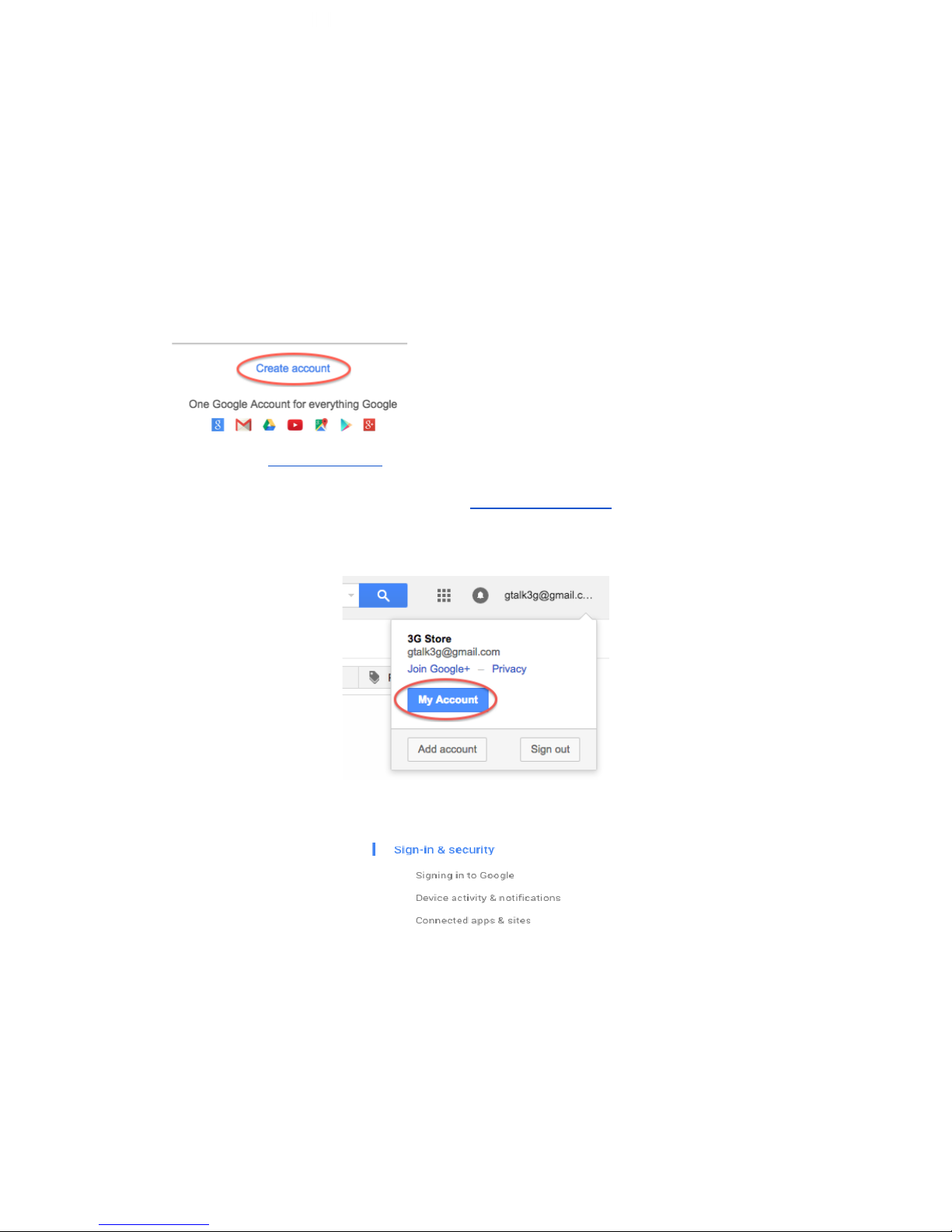
Creating a Gmail Account to be used by the IP Switch
1. Go to http://gmail.com and select Create Account
2. For this example we have created [email protected]
3. Once you log into your new account, you’ll need to confirm some settings
4. Click on the email account at the top right and a window will pop out
5. Click the “My Account” button
6. A new window will open showing your Account settings
7. Select “Sign-in & Security” on the left
Page 46
46
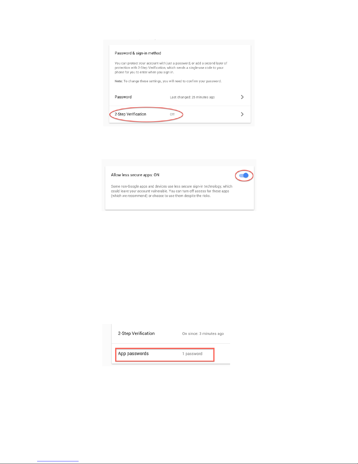
8. Scroll down to the “Signing in to Google” section
9. Confirm that 2-step Verification is Off**
10. Click “Connected apps & sites” on the left
11. Scroll down to the “Allow less secure apps” section and turn it ON
12. You may now close the My Account window and sign out of on the Gmail
Inbox page
Step Procedures with 2-Step Verification:
**If you prefer to have 2-step Verification turned ON, skip steps 9-11 above and
continue with the additional steps below:
1. Scroll down to the “Password & SIgn-In Method” section and select “2-step
Verification”
2. Google will walk you through the steps to add a cell phone number for
verification. It will send a code you will need to enter into the Gmail browser to
verify. Once this is done, it should show 2-step Verification is ON.
3. Next, go back to the “My Account” -> “Password & SIgn-In Method” section
of Gmail
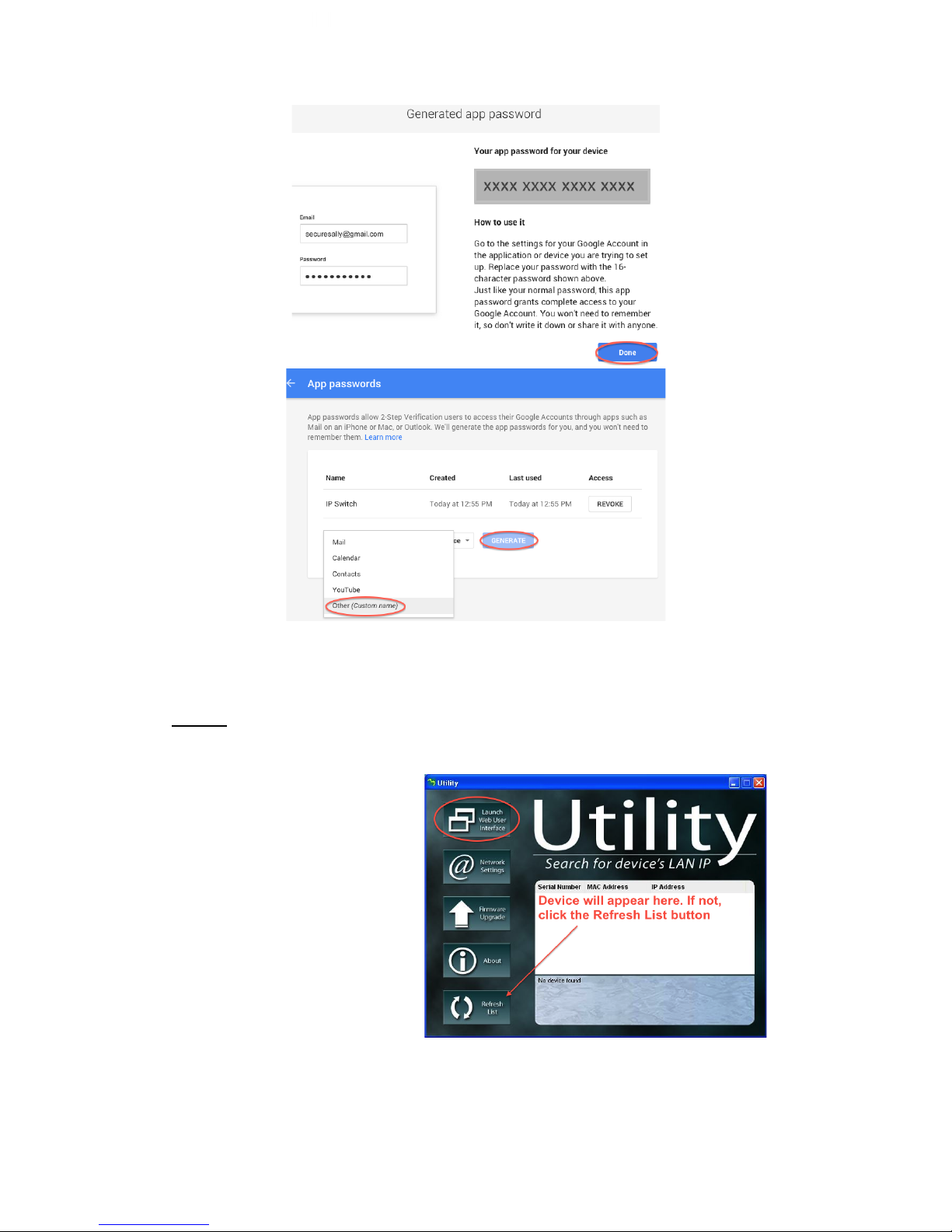
4. You’ll see a new field below 2-step Verification called “App Passwords”, click
on this
5. Click “Select Device” and choose “Other (Custom Name)”
6. Give it a unique name to identify it, here we’ve used “IP Switch”
7. Click “Generate”
8. Copy/ write the App password down (pictured, below right), as you will need it
to enter into the IP Switch later, then click “Done”
Page 47
47
Applying settings to your IP Switch
*NOTE: If configuring for the first time, steps must be done at the same location and
on the same local network as the IP Switch.
1. Use the Utility software
to locate your IP switch
on the network, then click
“Launch Web User
Interface” on the left - OR
- enter the local IP
address for the IP Switch
into your browser (this
can be obtained via your
router’s client list or a
LAN scan application
such as LANscan for
MAC, or Angry IP Scanner for Windows)
2. Log in when prompted
Page 48
48
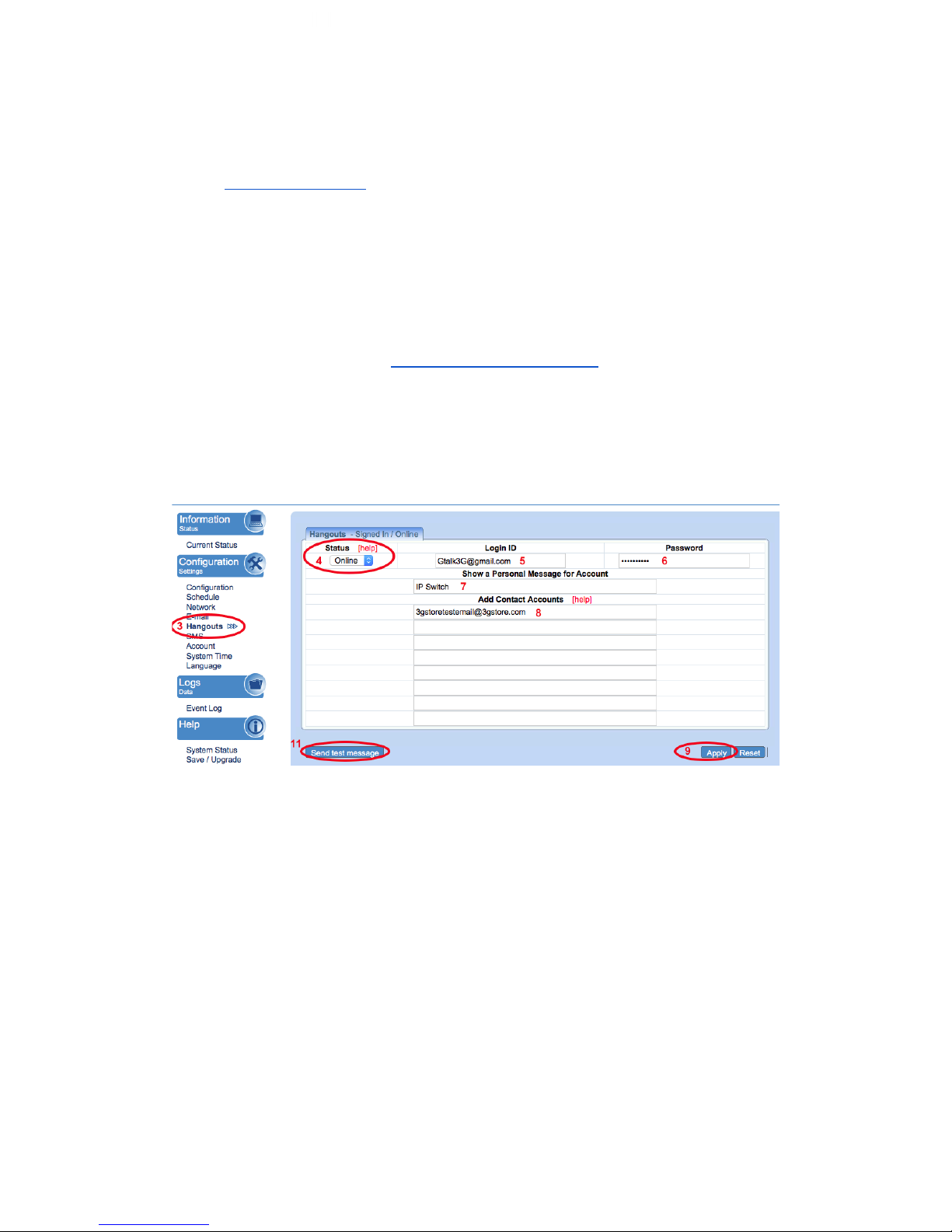
3. Under the ‘Configuration Settings’ section on the left click ‘Hangouts’
4. Under ‘Status’ at the top left of this page, select ‘Online’
5. For the ‘Login ID’ enter the Gmail Account you just created (i.e.
[email protected] ). This again will act as the IP Switch account.
6. Across from the Login ID is where you will enter the password/ APP
password associated with this new account. (see step 8 in the 2-step
Verification procedure above)
7. Next, provide a personal message for the Switch to use. Here, we’ve used IP
Switch
8. Under the ‘Add Contact Accounts’ enter your personal Gmail address (or
create a new one if necessary). This will be used to control the switch. In our
example we’ll be using [email protected]
9. Click ‘Apply’ at the bottom right corner of the web page. A pop up should
come up indicating that the settings have been applied - click OK
10. After a moment the Switch should indicate that it it has Signed In and is
Online
11. Click “Send test message” - this will prompt the IP Switch account to send
an Invitation to Chat/ test message to the control account
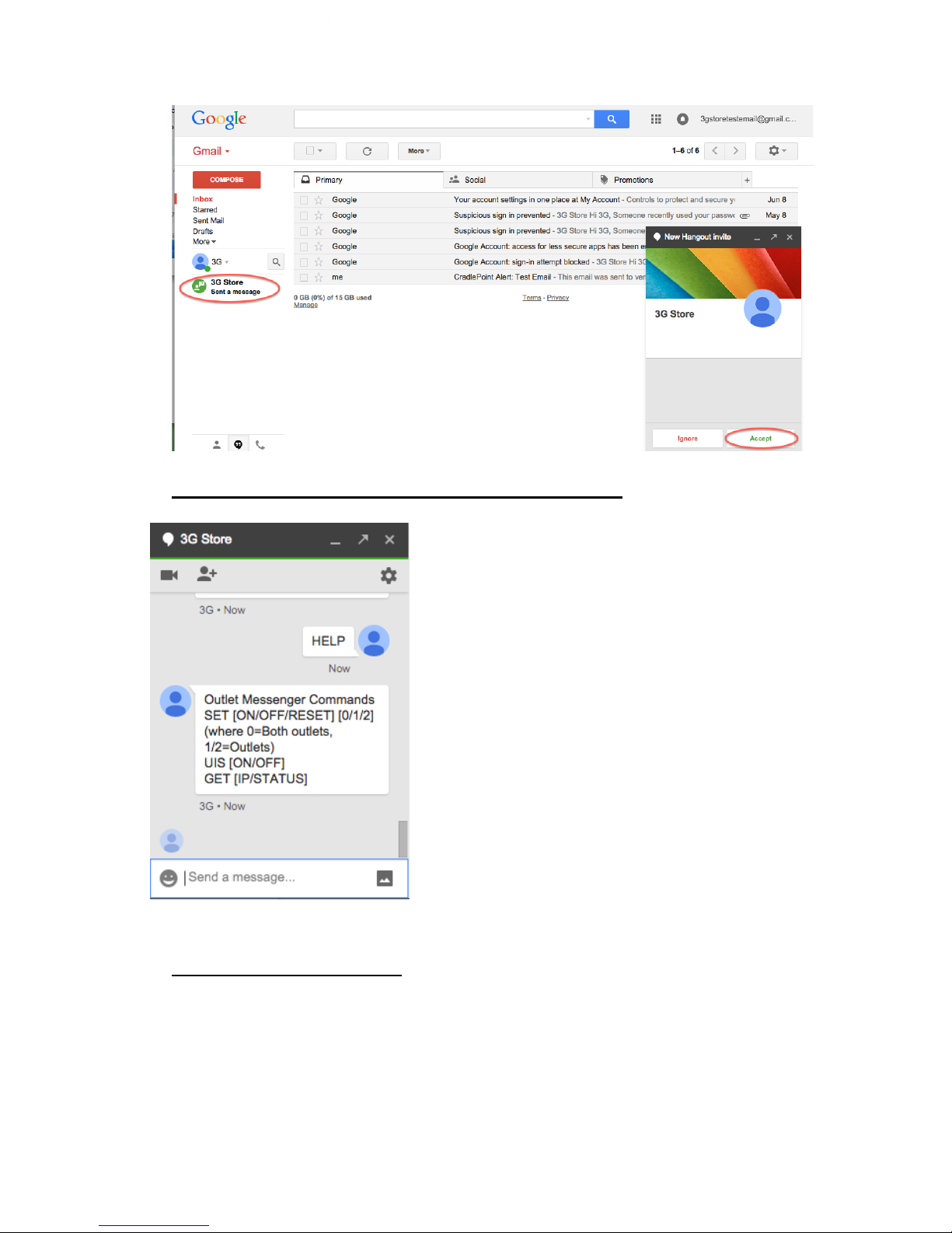
12. Log into the control Gmail account through a web browser
13. Once logged in, take a look at the bottom left corner - this is where your chat
history, including your chat contacts, is located.
14. Select the IP Switch Account name and you should get a pop up window in
the bottom right corner of the browser.
15. Click “Accept” to accept the chat invitation. Once accepted, you’ll be able to
start sending commands* to your Switch.
Page 49
49
*The Commands you will be able to send via Chat are:
Note: 0/1/2 = Variables are for specified power outlets
1, 2, or 0 for both ports
SET ON 0/1/2 ‐ This turns On the Power to the
specified port(s)
SET OFF 0/1/2 ‐ This turns off the power to the
specified port(s)
SET RESET 0/1/2 – This resets/power-cycles the
specific port(s)
GET IP – Retrieves current public (WAN) IP
address and local (LAN) IP Addresses
GET STATUS – Retrieves current status
information. Includes current ping times to all
target sites; indicates if port 1 or 2 are on/off
HELP - provides a list of available commands
Hangouts Troubleshooting:
If you receive an error when trying to get your IP Switch Gmail account to sign in (i.e.
errors #501 or #20512), please try the following:
1. Log into the Gmail account through a web browser and confirm there is no 2step verification set - OR, if it is, that you have the proper App Password
entered. If you are NOT using 2-step verification, you will also need to confirm
Page 50

50
the “Allow Less Secure Apps” option is turned ON. These are both found
under the “My Account” section of Gmail.
2. Wait at least 5 minutes while the Switch tries to Sign In. It will go back and
forth between signing in and showing the connection error - sometimes we’ve
seen this process take longer than a minute.
3. Turn the Status on the Google Talk Settings to Offline then click Apply. Log
into the Gmail account through a web browser and turn the “Allow Less
Secure Apps” option OFF, then sign out of the account. Next, sign right back
in and turn the “Allow Less Secure Apps” option back ON. Sign out of the
browser. Lastly, go back to the Google Talk settings on your Switch and
change the Status to Online. Click Apply. Wait a few minutes while the
Switch tries to connect.
4. If you’re still not getting the sign in or chats to work, some users have had
success reloading the firmware, if current. You may download current
firmware here: http://3gstore.com/ipswitchupdates
 Loading...