

MSK MSK690, MSK690B Datasheet
ISO-9001 CERTIFIED BY DSCC
HIGH VOLTAGE
AMPLIFIER
690
M.S.KENNEDY CORP.
4707 Dey Road Liverpool, N.Y. 13088 (315) 701-6751
FEATURES:
Adjustable High Voltage Power Supply to +75V
Low Cost TO-3 Package
High Slew Rate - 2000V/µS Typical
Wide Bandwidth - 30MHz Typical
Low Transition Time - 20nS Typical at Full Swing
MIL-PRF-38534 CERTIFIED
DESCRIPTION:
The MSK 690 is a high voltage differential ampifier designed for use in CRT displays. With the high voltage power
supply set to +65 volts, the output voltage of the MSK 690 can swing from +5 volts to +60 volts at a rate of 2000
v/µS. The MSK 690 boasts a 30 MHz typical -3dB bandwidth and 20nS typical transition time making it a good
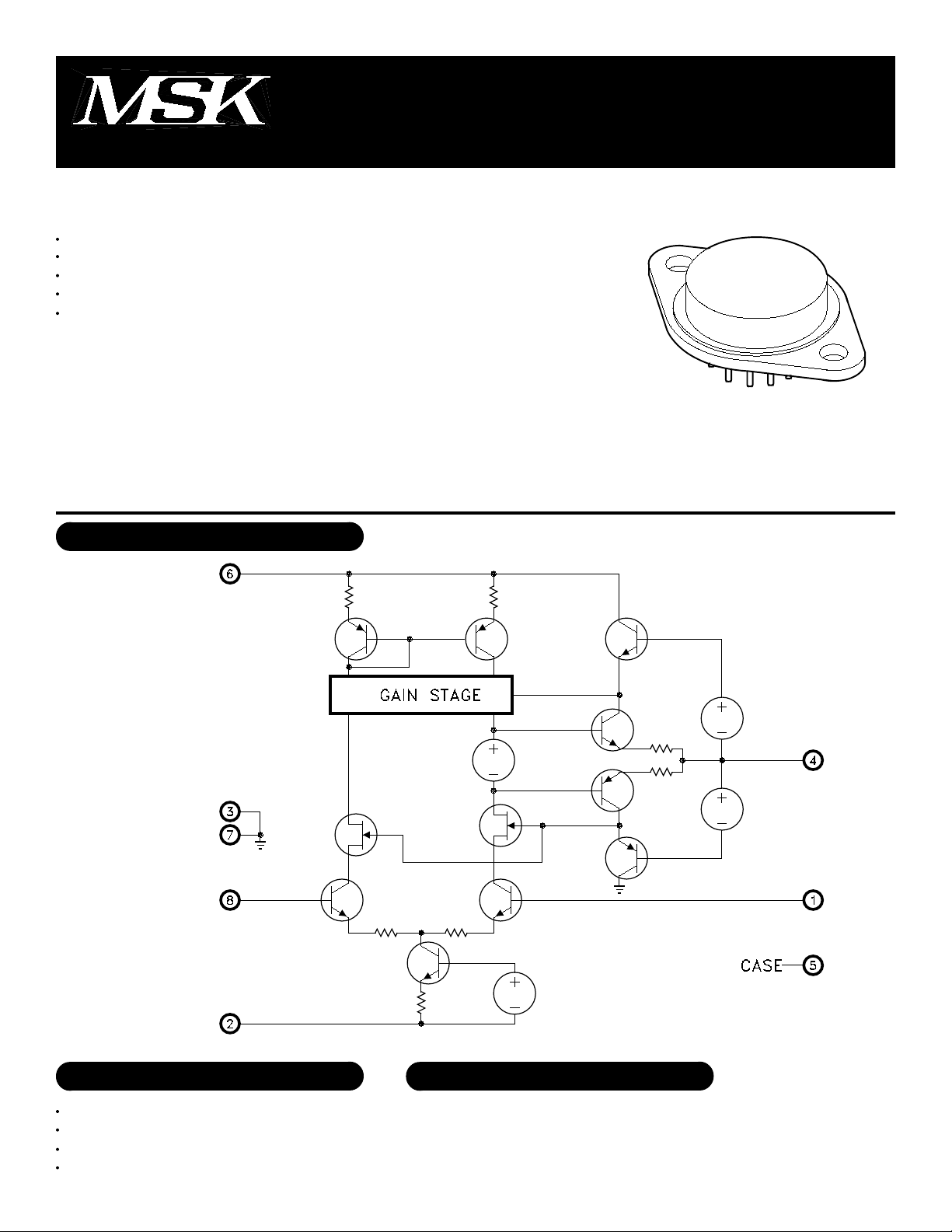
candidate for high speed systems. The circuit is packaged in a space efficient, hermetically sealed 8 pin TO-3 to
achieve good thermal efficiency and low cost. No isolation washer is necessary when heat sinking this device. The
MSK 690 is available in both industrial and military grades.
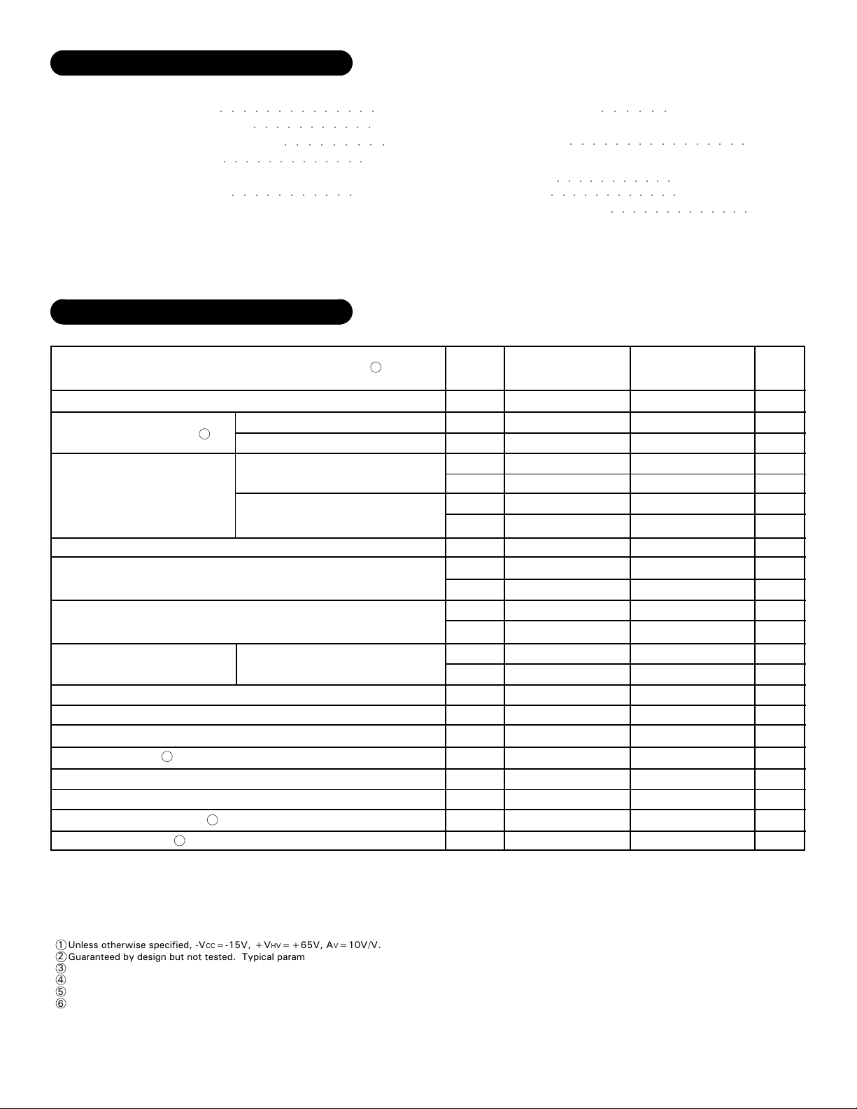
EQUIVALENT SCHEMATIC
TYPICAL APPLICATIONS
High Voltage Op-Amp
CRT Display Driver
High Voltage ATE Pin Driver
Level Shifter
PIN-OUT INFORMATION
Inverting Input
1
-VCC
2
Ground
3
Output
4
1
Non-Inverting Input
8
Ground
7
+VHV
6
Case Connection
5
Rev. A 8/00
ABSOLUTE MAXIMUM RATINGS
-VCC
+VHV
VIND
IOUT
RθJC
Supply Voltage
○○○○○○○○○○○○○○
High Voltage Supply
Differential Input Voltage
Output Current
○○○○○○○○○○○○○
Thermal Resistance
(Output Devices)
○○○○○○○○○○○
ELECTRICAL SPECIFICATIONS
Parameter
STATIC
Supply Voltage Range
Quiescent Current
INPUT
Input Bias Current
Input Offset Current
Output Offset Voltage
OUTPUT
Output Voltage (High)
Output Voltage (Low)
Output Current
TRANSFER CHARACTERISTICS
Slew Rate
Open Loop Voltage Gain
Bandwidth (-3dB)
2
2
2
2
○○○○○○○○○○○
○○○○○○○○○
100mA
42°C/W
Test Conditions
-VCC
+VHV
-VCC=-15V
+VHV=+65V
VIN=0V
VIN=0V
VOUT=+50VDC Nominal
AV=100V/V
RL=10KΩ
RL=10KΩ
RL=10KΩ
f=1KHz
VO=24Vpp
-20V
+75V
15V
1
Storage Temperature
TST
Lead Temperature
TLD
(10 Seconds)
Case Operating Temperature
TC
(MSK690B)
(MSK690)
Junction Temperature
TJ
Group A
Subgroup
2,3
2,3
2,3
2,3
2,3
Min.
-12
-
+40
-
1
-
-
1
-
-
1
-
-
1
-
-
1
-
-
4
4
-
4
-
-
55
-
75
1200
55
20
○○○○○○○○○○○○○○○○
○○○○○○○○○○○
○○○○○○○○○○○○
MSK690B MSK690
Typ.
-15
+65
20
20
40
45
±50
±100
±50
±50
±0.1
±0.1
60
5.0
100
2000
65
35
○○○○○○
-65°C to +150°C
-55°C to +125°C
-40°C to +85°C
○○○○○○○○○○○○○
-12
55
75
55
20
Typ.
-15
+65
20
-
-
-
-
-
-
-
-
-
-
-
40
-
±50
-
±50
-
±0.1
-
60
5.0
-
100
2000
65
35
Max.
-18
+75
27
30
55
60
±195
±250
±100
±200
±0.7
±1.0
-
7.0
-
-
-
-
Min.
+40
1200
Max.
-18
+75
27
-
55
-
±250
-
±150
-
±0.7
-
-
7.0
-
-
-
-
300°C
150°C
Units
V
V
mA
mA
mA
mA
µA
µA
µA
µA
V
V
V
V
mA
V/µS
dB
MHz
NOTES:
1
Unless otherwise specified, -V
2
Guaranteed by design but not tested. Typical parameters are for reference only.
3
Industrial grade devices shall be tested to subgroups 1 and 4 unless otherwise requested.
4
Military grade devices ('B' suffix) shall be 100% tested to subgroups 1,2,3 and 4.
5
Subgroup 5 and 6 testing available upon request.
6
Subgroup 1,4 TC=+25°C
Subgroup 2,5 TC=+125°C
Subgroup 3,6 TA=-55°C
CC=-15V, +VHV=+65V, AV=10V/V.
Rev. A 8/002
 Loading...