

MSK MSK4370U, MSK4370S, MSK4370D, MSK4370HU Datasheet
4707 Dey Road Liverpool, N.Y. 13088 (315) 701-6751
M.S.KENNEDY CORP.
ISO 9001 CERTIFIED BY DSCC
4370
10 AMP, 500V, 3 PHASE
IGBT BRUSHLESS
MOTOR CONTROLLER
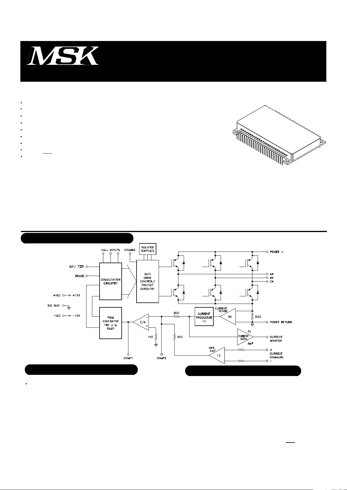
EQUIVALENT SCHEMATIC
FEATURES:
500 Volt Motor Supply Voltage
10 Amp Output Switch Capability
100% Duty Cycle High Side Conduction Capable
Shoot-Through/Cross Conduction Protection
Hall Sensing and Commutation Circuitry on Board
"Real" Four Quadrant Torque Control Capability
Good Accuracy Around the Null Torque Point
Isolated Package Design for High Voltage Isolation Plus Good Thermal Transfer
60°/ 120º Phasing Selectable
TYPICAL APPLICATIONS
3 Phase Brushless DC Motor Control
Servo Control
Fin Actuator Control
Gimbal Control
AZ-EL Control
PIN-OUT INFORMATION
Power+
CØ
BØ
AØ
Power Return (GND)
Current Command +
Current Command -
Current Monitor
Compensation 2
60°/120°
+Vcc
-Vcc
Hall Input A
Hall Input B
Hall Input C
Compensation 1
SIG GND
Brake
Disable
MIL-PRF-38534 QUALIFIED
1
DESCRIPTION:
The MSK 4370 is a complete 3 Phase IGBT Bridge Brushless Motor Control System in an electrically isolated
hermetic package. The hybrid is capable of 10 amps of output current and 500 volts of DC bus voltage. It has the
normal features for protecting the bridge. Included is all the bridge drive circuitry, hall sensing circuitry, commutation
circuitry and all the current sensing and analog circuitry necessary for closed loop current mode (torque) control.
When PWM'ing, the transistors are modulated in locked anti-phase mode for the tightest control and the most
bandwidth. Provisions for applying different compensation schemes are included. The MSK 4370 has good thermal
conductivity of the IGBT's due to isolated substrate/package design that allows direct heat sinking of the hybrid
without insulators. The anti-parallel commutation diodes are ultrafast recovery types for high efficiency/low switch-
ing losses.
PRELIMINARY Rev. A 6/00
500V
±13.5V
+18V
-18V
10A
20A
POWER SUPPLY CURRENT
+Vcc
-Vcc
PWM
Free Running Frequency
CONTROL
Transconductance
Current Monitor
Output Offset
HALL INPUTS
Low Level Input Voltage
High Level Input Voltage
ERROR AMP
Input Voltage Range
Slew Rate
Output Voltage Swing
Gain Bandwidth Product
Large Signal Voltage Gain
OUTPUT
Rise Time
Fall Time
Breakdown Voltage
Leakage Current
Voltage Drop Across Bridge
Diode Forward Voltage
trr
Dead Time
High Voltage Supply
Current Command Input
Continuous Output Current
Peak Output Current
+Vcc=+15V
-Vcc=-15V
No Clock Sync
±8 Amps Output
±8 Amps Output
@ 0 Volts Command
@ 50µA
@ 500V
@ 10 Amps
@ 10 Amps
IF=10 Amps, di/dt=100A/µS
mA
mA
KHz
V/amp
V/amp
mAmp
Volts
Volts
Volts
V/µSec
Volts
MHz
V/mV
µSec
µSec
Volts
µAmps
Volts
Volts
nSec
µSec
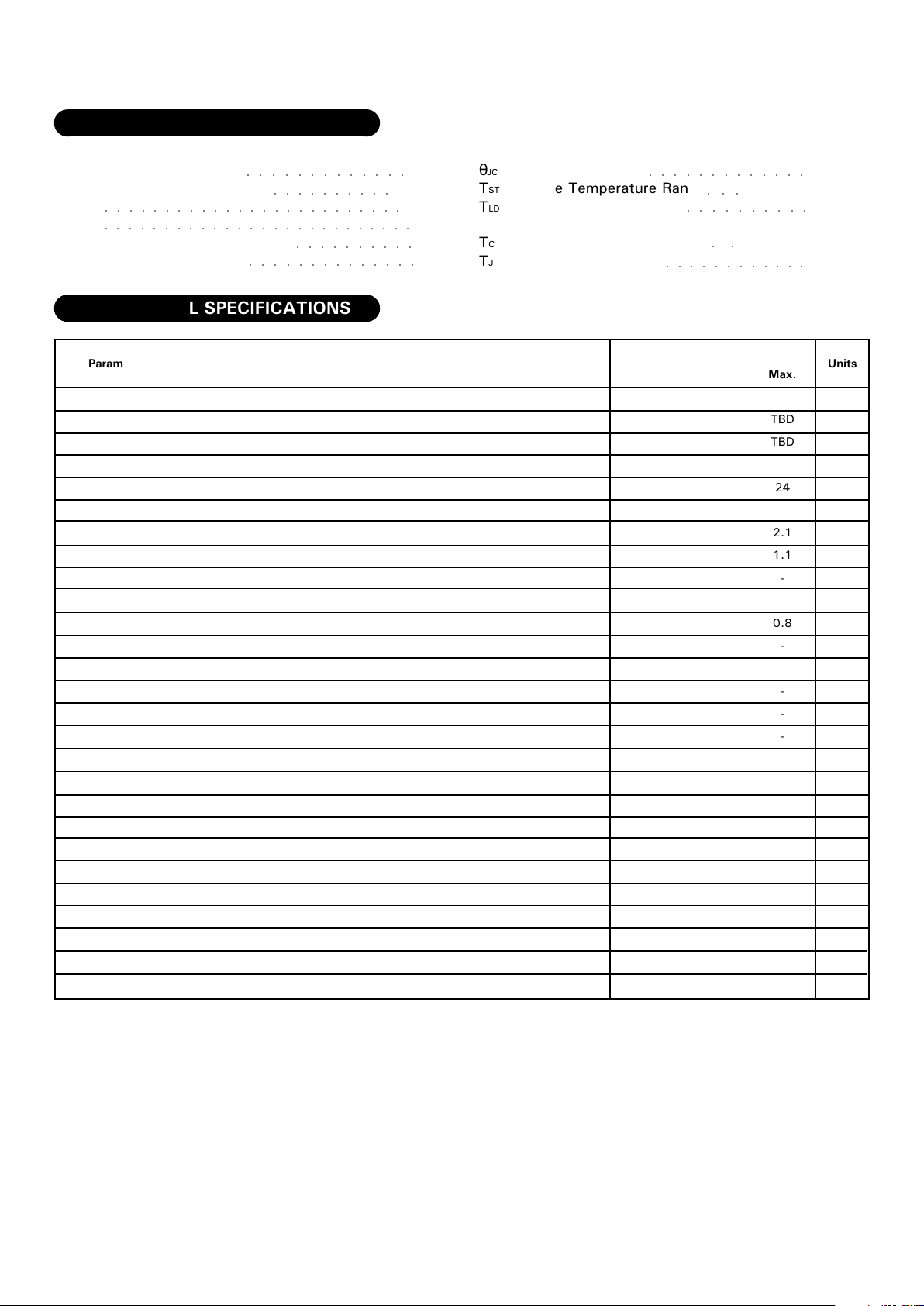
ABSOLUTE MAXIMUM RATINGS
V+
VIN
+Vcc
-Vcc
IOUT
IPK
1.5°C/W
-65°C to +150°C
+300°C
-55°C to +125°C
+150°C
○○○○○○○○○○○○○
○○○○○○○○○○
θJC
TST
TLD
TC
TJ
○○○○○○○○○○○○
○○○○○○○○○○
○○○○○○○○○○○○○
○○○○○○○○○○
○○
Parameter
ELECTRICAL SPECIFICATIONS
Units
Max.
TBD
TBD
24
2.1
1.1
-
0.8
-
-
-
-
-
-
-
-
-
50
5
1.5
60
-
MSK 4370
Typ.
TBD
TBD
22
2
1
±5.0
-
-
±12
8
±13
6.5
275
2
2
-
-
-
-
-
2
Test Conditions
○○○
○○○○○○○○○○○○○○
Min.
TBD
TBD
20
1.9
0.9
-
-
3.0
±11
6.5
±12
-
175
-
-
500
-
-
-
-
-
Thermal Resistance
Storage Temperature Range
Lead Temperature Range
(10 Seconds)
Case Operating Temperature
Junction Temperature
All Ratings: Tc=+25°C Unless Otherwise Specified
2
PRELIMINARY Rev. A 6/00
○○○○○○○○○○○○○○○○○○○○○○○○○○
○○○○○○○○○○○○○○○○○○○○○○○○○
 Loading...