

MSK MSK4351D, MSK4351U, MSK4351HU, MSK4351ED, MSK4351S Datasheet
...
M.S.KENNEDY CORP.
ISO-9001 CERTIFIED BY DSCC
50 AMP, 500 VOLT IGBT PLUS DIODE
FULLY ISOLATED
SMART POWER 3-PHASE MOTOR
DRIVE POWER HYBRID
4351
4707 Dey Road Liverpool, N.Y. 13088
FEATURES:
MIL-PRF-38534 CERTIFIED
(315) 701-6751
500V, 50 Amp Capability at 110°C
Fully Isolated Bridge
Ultra Low Thermal Resistance
Integral Free Wheeling Fast Recovery Epitaxial Diode (FRED)
Self-Contained, Smart Lowside/Highside Drive Circuitry and Isolated Supply
Adjustable Deadtime
Capable of Switching Frequencies to 20KHz
Isolated Case Allows Direct Heat Sinking; On Board Temp Sensor
Case Bolt-down Design Allows Superior Heat Dissipation
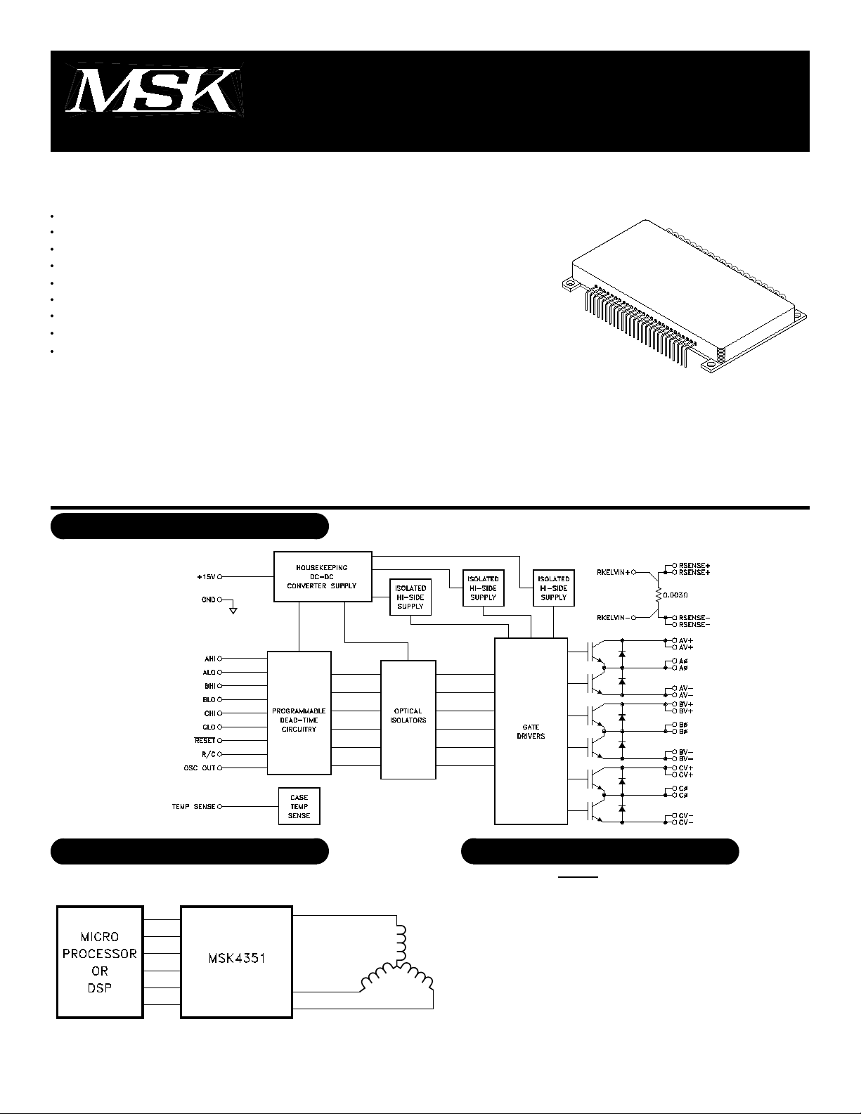
DESCRIPTION:
The MSK 4351 is a 50 Amp, 3 Phase Isolated Bridge Smart Power Motor Drive Hybrid with a 500 volt rating. The output
switches are Insulated Gate Bipolar Transistors (IGBT's) tailored for high switching speeds. The free-wheeling diodes are Fast
Recovery Epitaxial Diodes (FRED's) to provide matched current capabilities with the IGBT's and are specified with excellent reverse
recovery times at high current ratings. The bridge is optically isolated from the control circuitry. This new smart power motor drive
hybrid is compatible with 5v CMOS or TTL logic levels. The internal circuitry prevents simultaneous turn-on of the in-line half bridge
transistors with adjustable deadtime to prevent shoot-through. Undervoltage lockout shuts down the bridge when the supply voltage
gets to a point of incomplete turn-on of the output switches. The isolated internal high-side power supply derived from the +15 volt
supply completely eliminates the need for 3 floating independent power supplies for the high-side drive.
EQUIVALENT SCHEMATIC
TYPICAL APPLICATIONS
3 PHASE SIX STEP DC BRUSHLESS MOTOR DRIVE
OR 3 PHASE SINUSOIDAL INDUCTION MOTOR DRIVE
PIN-OUT INFORMATION
1
+15V
2
GND
3
AHI
4
ALO
5
BHI
6
BLO
7
+15V
8
GND
9
CHI
10
CLO
11
+15V
12
GND
1
13
RESET
14
R/C
15
+15V
16
N/C
17
OSCOUT
18
GND
19
N/C
20
N/C
21
N/C
22
N/C
23
N/C
24
TEMP SENSE
25
RKELVIN+
26
RKELVIN-
27
RSENSE-
28
RSENSE-
29
RSENSE+
30
RSENSE+
31
CV-
32
CV-
33
CØ
34
CØ
35
CV+
36
CV+
PRELIMINARY Rev. A 11/01
37
38
39
40
41
42
43
44
45
46
47
48
BV-
BV-
BØ
BØ
BV+
BV+
AV-
AV-
AØ
AØ
AV+
AV+
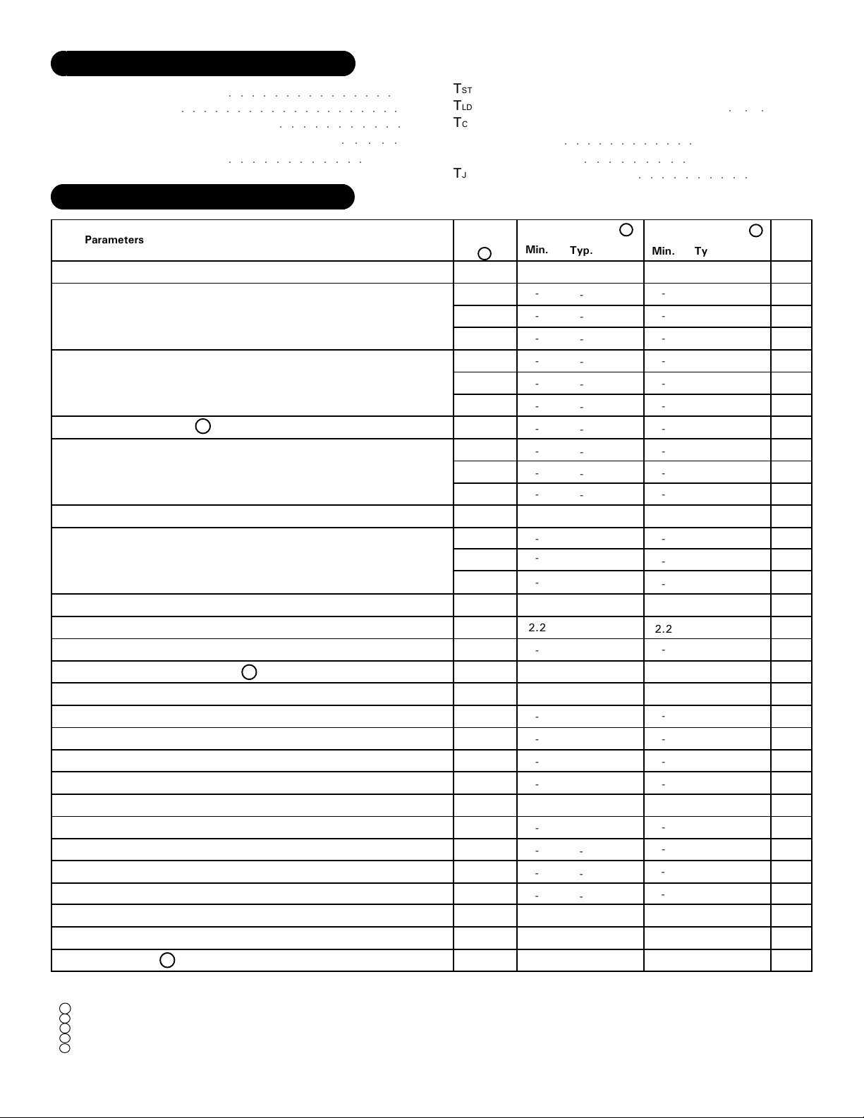
ABSOLUTE MAXIMUM RATING
High Voltage Supply
V+
Logic Supply
VCC
Continuous Output Current
IOUT
Peak Output Current (1 pulse, 10µSec)
IPK
Thermal Resistance
θJC
(Output Switches) (Junction to Case)
○○○○○○○○○○○○○○○○○○○○
○○○○○○○○○○○○○○○
○○○○○○○○○○○
○○○○○○○○○○○○
500V
○○○○○
0.38°C/W
18V
50A
60A
Storage Temperature Range
TST
Lead Temperature Range(10 Seconds)
TLD
Case Operating Temperature
TC
MSK4351
MSK4351H/E
Junction Temperature
TJ
○○○○○○○○○○○○
○○○○○○○○○
○○○○○○○○○○
-65°C to +150°C
300°C
○○○
-40°C to +85°C
-55°C to +125°C
+150°C
ELECTRICAL SPECIFICATIONS
Parameters
OUTPUT CHARACTERISTICS
VC-E On Voltage (Each IGBT)
Instantaneous Forward Voltage
(FRED Flyback Diode)
Reverse Recovery Time 1
Leakage Current
BIAS SUPPLY CHARACTERISTICS
Quiescent Bias Current
INPUT SIGNALS CHARACTERISTICS
Positive Trigger Threshold Voltage
Negative Trigger Threshold Voltage
SWITCHING CHARACTERISTICS 1
Upper Drive:
Turn-On Propagation Delay
Turn-Off Propagation Delay
Turn-On
Turn-Off
Lower Drive:
Turn-On Propagation Delay
Turn-Off Propagation Delay
Turn-On
Turn-OffV+=270V, IC=50A
TEMPERATURE SENSOR
Initial Accuracy
Overall Accuracy 1
ID=50A,di/dt=100A/uS,Vr=350V
Test Conditions
IC=50A
ID=50A
V+=500V
V+=400V
V+=500V
VCC=15V
V+=270V, IC=50A
V+=270V, IC=50A
TC=25°C
TMIN ≤ TC ≤ TMAX
All Ratings: Tc = +25°C Unless Otherwise Specified
Group A
Subgroup
5
1
2
3
1
2
3
-
1
2
3
1
2
3
1,2,3
1,2,3
4
4
4
4
4
4
4
4
1
2,3
MSK 4351H/E 3
Min.
2.2
Typ.
-
-
-
-
-
-
-
-
-
-
-
-
-
-
-
-
-
-
-
-
-
-
-
-
-
-
-
-
-
-
-
-
-
-
-
-
-
-
-
-
-
-
-
-
-
-
-
±0.5
±1.3
Max.
2.2
2.1
TBD
1.8
1.5
2.5
180
400
1.5
400
TBD
TBD
TBD
-
0.8
TBD
TBD
45
350
TBD
TBD
45
350
±2.0
±4.0
MSK 4351 2
Min.
-
-
-
-
-
-
-
-
-
-
-
-
-
2.2
-
-
-
-
-
-
-
-
-
-
±0.5
-
±1.3
Typ.
-
-
-
-
-
-
-
-
-
-
-
-
-
-
-
-
-
-
-
-
-
-
-
Max.
2.3
-
-
1.8
-
-
180
400
-
-
TBD
-
-
-
0.8
TBD
TBD
45
350
TBD
TBD
45
350
±3.0
±5.0
UNITS
V
V
V
V
V
V
nS
uA
mA
uA
mA
mA
mA
V
V
nS
nS
nS
nS
nS
nS
nS
nS
°C
°C
NOTES:
1
Guaranteed by design but not tested. Typical parameters are representative of actual device performance but are for reference only.
2
Industrial grade and "E" suffix devices shall be tested to subgroups 1 and 4 unless otherwise specified.
3
Military grade devices ("H" suffix) shall be 100% tested to subgroups 1,2,3 and 4.
4
Subgroups 5 and 6 testing available upon request.
5
Subgroup 1,4
2,5
3,6
TA=TC=+25°C
TA=TC=+125°C
TA=TC=-55°C
2
PRELIMINARY Rev. A 11/01
 Loading...