

MSK MSK4322HD, MSK4322HS, MSK4322HU, MSK4322S, MSK4322U Datasheet
...
ISO-9001 CERTIFIED BY DSCC
20 AMP, 200 VOLT MOSFET
SMART POWER 3-PHASE MOTOR
4322
M.S.KENNEDY CORP.
M.S. KENNEDY CORP.
4707 Dey Road Liverpool, N.Y. 13088 (315) 701-6751
FEATURES:
200V, 20 Amp Capability
Ultra Low Thermal Resistance - Junction to Case - 1.0°C/W (Each MOSFET)
Self-Contained, Smart Lowside/Highside Drive Circuitry
Under-Voltage Lockout, Internal 2µS Deadtime
Capable of Switching Frequencies to 25KHz
Isolated Case Allows Direct Heat Sinking
Case Bolt-down Design Allows Superior Heat Dissipation
DESCRIPTION:
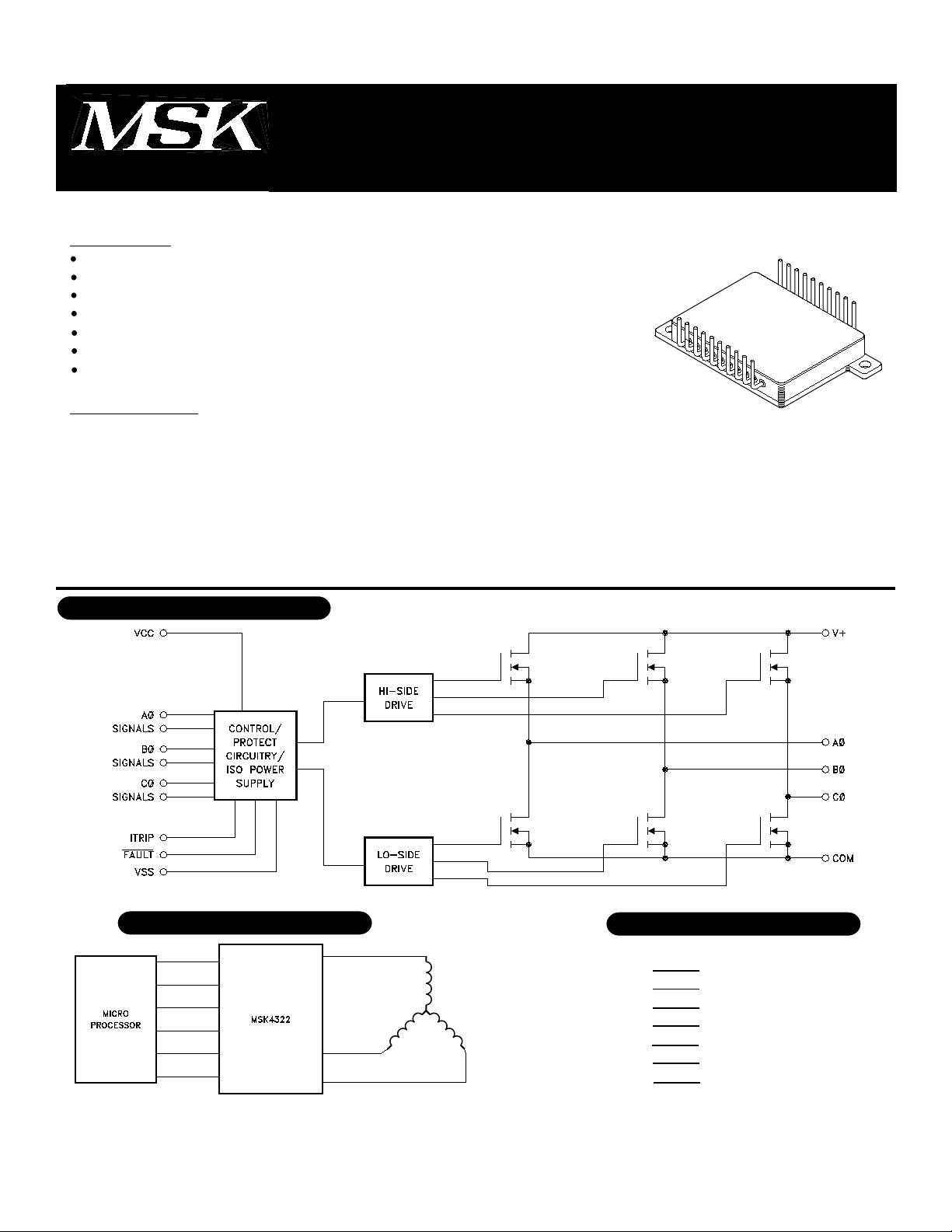
The MSK 4322 is a 20 Amp, 3 Phase Bridge Smart Power Motor Drive Hybrid with a 200 volt rating on the
output switches. The output switches are power MOSFETs with intrinsic fast-recovery diodes for the free-
wheeling currents of motor drives. This new smart power motor drive hybrid is compatible with 5V CMOS or
TTL logic levels. The internal circuitry prevents simultaneous turn-on of the in-line half bridge transistors with a
built-in 2µS deadtime to prevent shoot-through. Undervoltage lockout shuts down the bridge when the supply
voltage gets to a point of incomplete turn-on of the output switches. The internal high-side boot strap power
supply derived from the +15 volt supply completely eliminates the need for 3 floating independent power sup-
plies for the high-side drive. Current sense circuitry is provided to sense current from an external resistor to shut
down the bridge for overcurrent.
DRIVE POWER HYBRID
MIL-PRF-38534 QUALIFIED
EQUIVALENT SCHEMATIC
TYPICAL APPLICATIONS PIN-OUT INFORMATION
TYPICAL APPLICATIONSPIN-OUT INFORMATION
3 PHASE SIX STEP DC BRUSHLESS MOTOR DRIVE
OR 3 PHASE SINUSOIDAL INDUCTION MOTOR DRIVE
1
2
3
4
5
6
7
8
9
10
VCC
AØHIN
BØHIN
CØHIN
AØLIN
FAULT
CØLIN
BØLIN
VSS
ITRIP
20
19
18
17
16
15
14
13
12
11
N/C
AØ
V+
N/C
N/C
BØ
N/C
N/C
CØ
COM
1
PRELIMINARY Rev. A 6/00
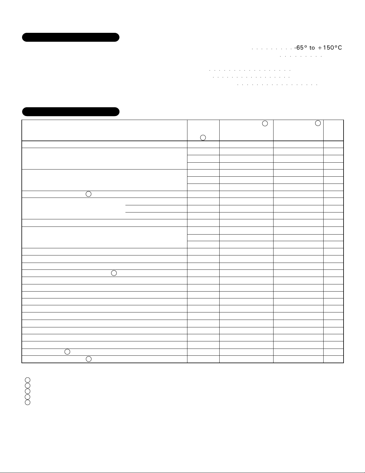
ABSOLUTE MAXIMUM RAT-
V+ High Voltage Supply. . . . . . . 200V
INGS
VCC Logic Supply . . . . . . . . . . 18V
IOUT Continuous Output Current . . . 20A
IPK Peak Output Current. . . . . . . 30A
θJC Thermal Resistance . . . . . . 1.0°C/W
(Output Switches) (Junction to Case)
ELECTRICAL SPECIFICATIONS
Storage Temperature Range
TsT
Lead Temperature Range(10 Seconds)
TLD
Case Operating Temperature
TC
MSK 4322
MSK 4322H
Junction Temperature
TJ
○○○○○○○○○○○○○○○○○
○○○○○○○○○○○○○○○○○
○○○○○○○○○○○○○○○○○
○○○○○○○○○
○○○○○○○○○
-65° to +150°C
300°C
-40°C to +85°C
-55°C to +125°C
+175°C
Parameters
OUTPUT CHARACTERISTICS
VDS(ON) (Each Transistor)
Instantaneous Forward Voltage
(Intrinsic Diode)
Reverse Recovery Time 1
Leakage Current
BIAS SUPPLY CHARACTERISTICS
Quiescent Bias Current
INPUT SIGNAL CHARACTERISTICS
Positive Trigger Threshold Voltage
Negative Trigger Threshold Voltage
SWITCHING CHARACTERISTICS
Upper Drive:
Turn-On Propagation Delay
Turn-Off Propagation Delay
Turn-On
Turn-Off
Lower Drive:
Turn-On Propagation Delay
Turn-Off Propagation Delay
Turn-On
Turn-Off
Dead Time 1
Minimum Pulse Width 1
Test Conditions
V+ = 200V
V+ = 160V
V+ = 200V
(non-switching)
V
CC = 15V
V
CC = 15V
1
V+ = 100V, V
V+ = 100V, V
ID = 20A
IS = 20A
VCC = 15V
CC = 15V, ID = 20A
CC = 15V, ID = 20A
GROUP A
SUBGROUP
5
1
2
3
1
2
3
-
1
2
3
1
2
3
1,2,3
1,2,3
-
-
-
-
-
-
-
-
-
-
MSK 4322H
Min. Typ. Max.
-
-
-
-
-
-
-
-
-
-
-
-
-
2.2
-
2.0
-
5.0
-
TBD
-
2.0
-
TBD
-
TBD
-
600
-
750
-
3.0
-
TBD
-
-
-
-
-
-
6
12
TBD
-
0.8
-
-
-
-
-
TBD
-
TBD
-
45
-
350
-
-
-
-
-
-
300
TBD
-
TBD
-
45
-
350
-
2
-
-
-
3
MSK 4322
Min. Typ. Max.
-
-
-
-
-
-
-
-
-
-
-
-
-
2.2
-
-
-
-
-
-
-
-
-
-
300
2
UNITS
2.0
-
-
-
2.0
-
-
-
600
-
750
-
-
-
-
-
-
-
0.8
-
TBD
-
TBD
-
45
-
350
-
TBD
-
TBD
-
45
-
350
-
2
-
V
-
V
-
V
V
-
V
-
V
nS
µA
-
mA
-
µA
6
mA
-
mA
-
mA
-
V
V
nS
nS
nS
nS
nS
nS
nS
nS
-
µS
-
nS
NOTES:
1 Guaranteed by design but not tested. Typical parameters are representative of actual device performance but are for reference only.
2 Industrial grade devices shall be tested to subgroups 1 and 4 unless otherwise specified.
3 Military grade devices ("H" suffix) shall be 100% tested to subgroups 1, 2, 3 and 4.
4 Subgroups 5 and 6 testing available upon request.
5 Subgroup 1, 4 TA =TC = +25°C
2, 5 TA = TC =+125°C
3, 6 TA = TC =-55°C
2
PRELIMINARY Rev. A 6/00
 Loading...