

MSK MSK4250, MSK4250H Datasheet
ISO 9001 CERTIFIED BY DSCC
10 AMP, 75V, H-BRIDGE
MOSFET BRUSHED
M.S.KENNEDY CORP.
4707 Dey Road Liverpool, N.Y. 13088 (315) 701-6751
MOTOR CONTROLLER
4250
FEATURES:
75 Volt Motor Supply Voltage
10 Amp Output Switch Capability
100% Duty Cycle High Side Conduction Capable
Shoot-Through/Cross Conduction Protection
"Real" Four Quadrant Torque Control Capability
Good Accuracy Around the Null Torque Point
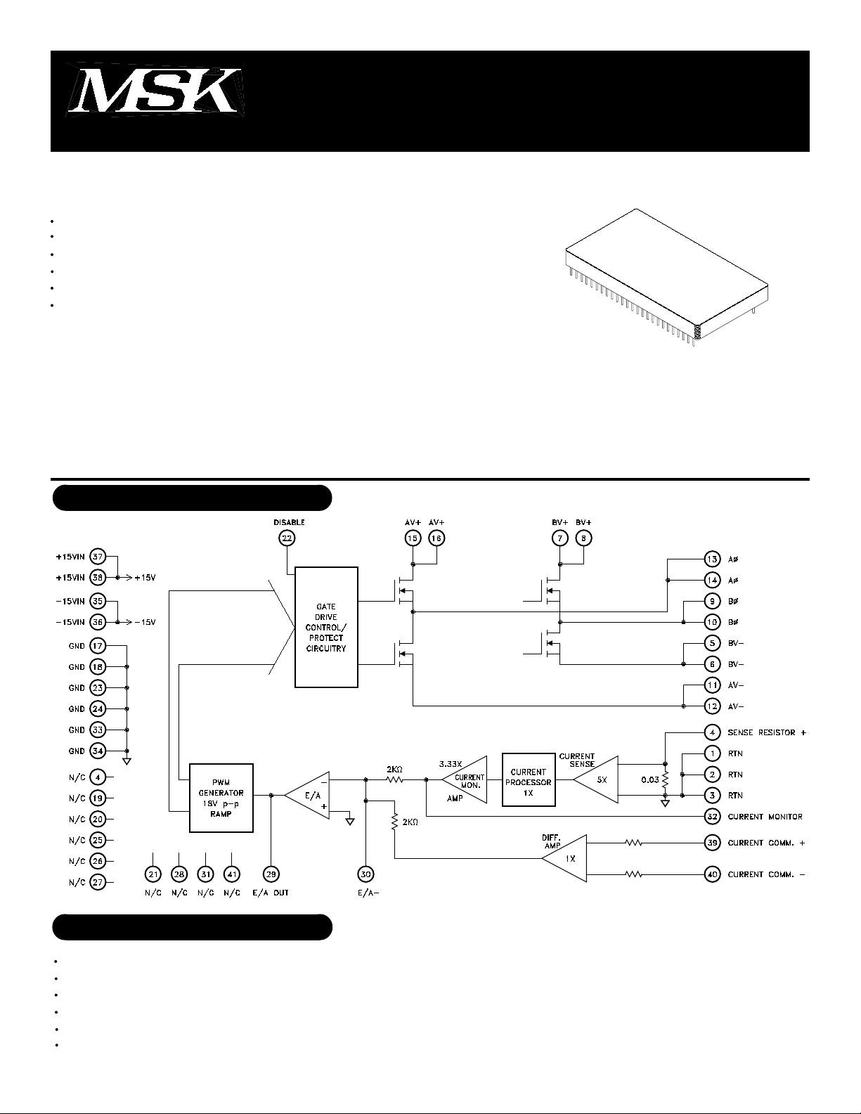
DESCRIPTION:
The MSK 4250 is a complete H-bridge MOSFET Brushed Motor Control System in an electrically isolated hermetic
package. The hybrid is capable of 10 amps of output current and 75 volts of DC bus voltage. It has the normal
features for protecting the bridge. Included is all the bridge drive circuitry, and all the current sensing and analog
circuitry necessary for closed loop current mode (torque) control. When PWM'ing, the transistors are modulated in
locked anti-phase mode for the tightest control and the most bandwidth. Provisions for applying different compensa-
tion schemes are included. The MSK 4250 has good thermal conductivity of the MOSFET's due to isolated substrate/
package design that allows direct heat sinking of the hybrid without insulators.
EQUIVALENT SCHEMATIC
MIL-PRF-38534 QUALIFIED
TYPICAL APPLICATIONS
Brushed DC Motor Control
Servo Control
Fin Actuator Control
Voice Coil Control
Gimbal Control
AZ-EL Control
1
PRELIMINARY Rev. - 11/00
ABSOLUTE MAXIMUM RATINGS
V+
VIN
+Vcc
-Vcc
IOUT
IPK
High Voltage Supply
Current Command Input
○○○○○○○○○○○○○○○○○○○○○○○○○
○○○○○○○○○○○○○○○○○○○○○○○○○
○○○○○○○○○○○○○○
○○○○○○○○○○
Continuous Output Current
Peak Output Current
○○○○○○○○○○○○○○
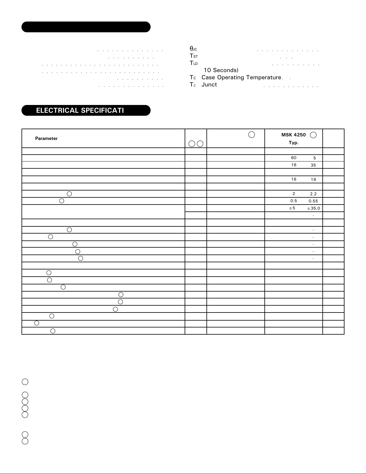
ELECTRICAL SPECIFICATIONS
Parameter
POWER SUPPLY REQUIREMENTS
+Vcc
-Vcc
PWM
Free Running Frequency
CONTROL
Transconductance
Current Monitor
ERROR AMP
Input Voltage Range
Slew Rate
Output Voltage Swing
Gain Bandwidth Product
Large Signal Voltage Gain
OUTPUT
Rise Time
Fall Time
Leakage Current
Voltage Drop Across Bridge (1 Upper and 1 Lower)
Voltage Drop Across Bridge (1 Upper and 1 Lower)
Drain-Source On Resistance (Each MOSFET)
Diode VSD
trr
Dead Time
1
1
1
1
7
7
1
1
1
1
1
1
1
±13.5V
○○○○○○○○○○
Test Conditions
@ +15V
@ -15V
±8 Amps Output
±8 Amps Output
@ 0 Volts CommandOutput Offset
@ 64V, +150°C Junction
1
1
@ 10 Amps, 150°C Junction
6
@ 10 Amps
@10Amps, +150°C
@ 10 Amps, Each FET
IF=10 Amps, di/dt=100A/µS
75V
+16V
-18V
10A
20A
Junction
θJC
Thermal Resistance
TST
Storage Temperature Range
TLD
Lead Temperature Range
(10 Seconds)
TC
Case Operating Temperature
TJ
Junction Temperature
All Ratings: Tc=+25°C Unless Otherwise Specified
Group A
Subgroup
5
4
1,2,3
1,2,3
4,5,6
4,5,6
4,5,6
4
5,6
-
-
-
-
-
-
-
-
-
-
-
-
-
-
MSK 4250H
Min.
-
-
15
1.9
0.45
-
-
±11
6.5
±12
-
175
-
-
-
-
-
-
-
-
-
Typ.
60
16
16
2
0.5
±5.0
-
±12
8
±13
6.5
275
100
100
-
-
-
-
-
280
2
○○○○○○○○○○○○○
-65°C to +150°C
○○○
○○○○○○○○○○
○○
-55°C to +125°C
○○○○○○○○○○○○
Min.
-
-
14
1.8
0.45
-
-
±11
6.5
±12
-
175
-
-
-
-
-
-
-
-
-
MSK 4250
Typ.
60
16
16
2
0.5
±5.0
-
±12
8
±13
6.5
275
100
100
-
-
-
-
-
280
2
3
Max.
85
35
18
2.1
0.55
±25.0
±50.0
-
-
-
-
-
-
-
750
0.3
0.6
0.026
2.6
-
-
2
Max.
85
35
19
2.2
0.55
±35.0
-
-
-
-
-
-
-
-
750
0.3
0.6
0.026
2.6
-
-
3.1°C/W
+300°C
+150°C
Units
mA
mA
KHz
Amp/Volt
V/Amp
mAmp
mAmp
Volts
V/µSec
Volts
MHz
V/mV
nSec
nSec
µAmps
Volts
Volts
Ω
Volts
nSec
µSec
NOTES:
1 Guaranteed by design but not tested. Typical parameters are representative of actual device
performance but are for reference only.
2 Industrial grade devices shall be tested to subgroups 1 and 4 unless otherwise specified.
3 Military grade devices ("H" Suffix) shall be 100% tested to Subgroups 1, 2, 3 and 4.
4 Subgroups 5 and 6 testing available upon request.
5 Subgroup 1, 4 TA = TC = +25°C
2, 5 T
3, 6 T
A = TC = +125°C
A = TC = -55°C
6 This is to be used for MOSFET thermal calculation only.
7 Measurements do not include offset current at 0V current command.
2
PRELIMINARY Rev. - 11/00
 Loading...