

MSK MSK4202RHU, MSK4202KRHU, MSK4202KRHD, MSK4202HRHS, MSK4202RHD Datasheet
...
ISO 9001 CERTIFIED BY DSCC
70 VOLT 10 AMP RAD-HARD
H-BRIDGE PWM MOTOR
4202RH
M.S.KENNEDY CORP.
4707 Dey Road Liverpool, N.Y. 13088 (315) 701-6751
DRIVER/AMPLIFIER
FEATURES:
User Adjustable PWM Frequency
70 Volt, 10 Amp Capability
Self-Contained Smart Lowside/Highside Drive Circuitry
Internal PWM Generation, Shoot-through Protection
Isolated Case Allows Direct Heatsinking
On Board 5Volt Rad-Hard Regulator
Available Fully Screened To MIL-PRF-38534 Class K and Class H
Total Dose Rated to 100K RAD
Logic Level High Side Enable Control
Logic Level Disable Input
DESCRIPTION:
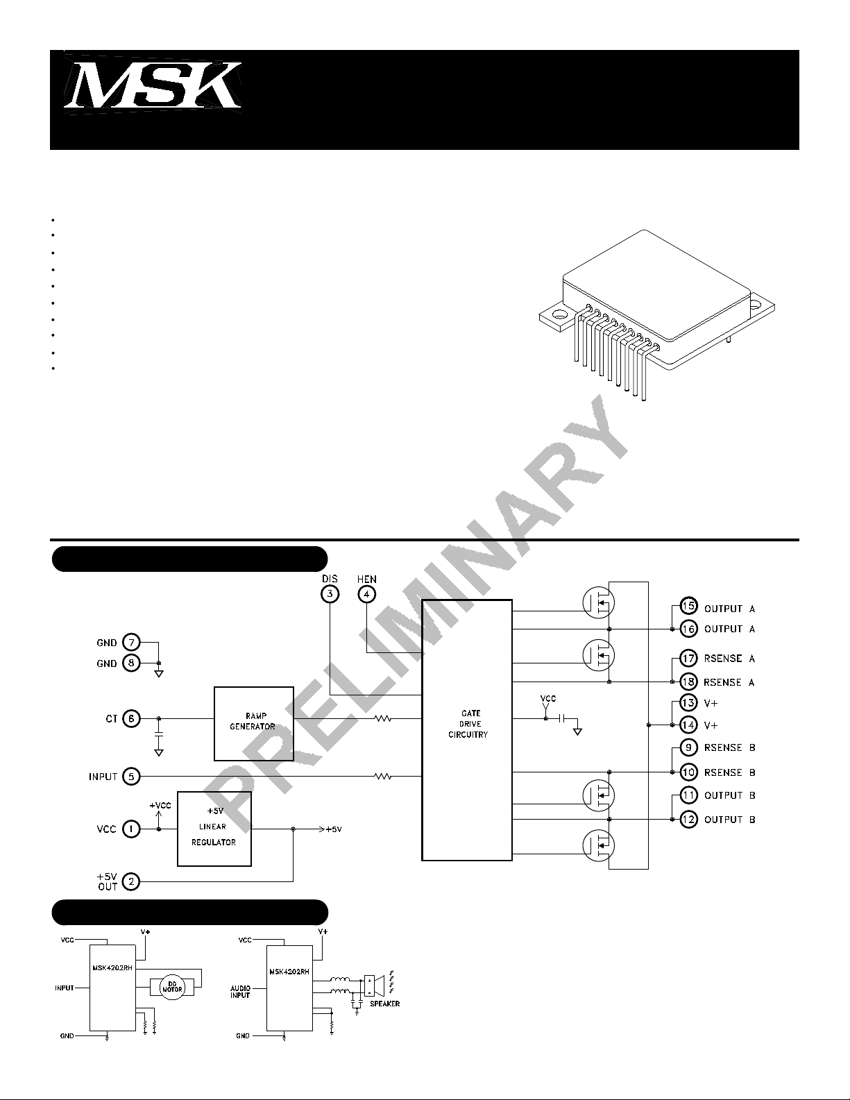
The MSK 4202RH is a radiation hardened complete H-Bridge hybrid intended for use in DC brushed motor control
applications or Class D switchmode amplification in space or other severe operating environments. The design will exhibit
high resistance to Single Event Effects (SEE), Single Event Gate Rupture (SEGR), total dose up to 100K RAD and neutron
tolerance for military applications. All of the drive/control circuitry for the lowside and highside switches are internal to the
hybrid, as well as a +5V linear regulator. The PWM circuitry is internal as well, leaving the user to only provide an analog
signal for the motor speed/direction, or audio signal for switchmode audio amplification. The MSK 4202RH is packaged in
a space efficient isolated 18 pin power package available in three lead form configurations that can be directly connected
to a heatsink.
EQUIVALENT SCHEMATIC
MIL-PRF-38534 QUALIFIED
CERTIFIED TO CLASS K
TYPICAL APPLICATIONS
1
Rev. A 5/00
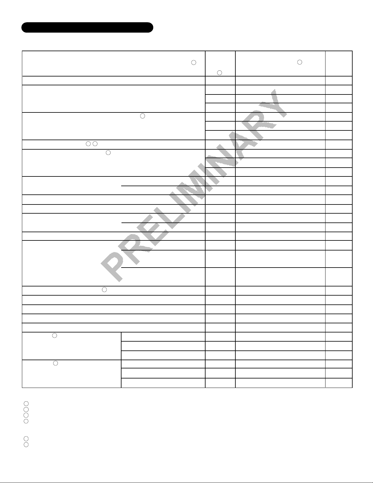
ELECTRICAL SPECIFICATIONS
Parameter
OUTPUT CHARACTERISTICS
VDS(ON) Voltage (Each MOSFET)
Instantaneous Forward Voltage, Each MOSFET
(Intrinsic Diode)
2
RDS (ON) each mosfet
Leakage Current, Each MOSFET
PWM Frequency
Vcc SUPPLY CHARACTERISTICS
Quiescent Current
+5V OUT
OUTPUT DUTY CYCLE
SWITCHING CHARACTERISTICS
Rise-Time
Fall-Time
Dead-Time
LOGIC CONTROL INPUTS
DIS Input
HEN Input
2
2
6
VIN=5V
VIN=OV
2
2
Output A=100% Duty Cycle High
Output B = 0% Duty Cycle Low
Output A=0% Duty Cycle Low
Output B = 100% Duty Cycle High
Test Conditions
ID=10A
2
IS=10A
ID =10A TC =125°C
V+=70V
CT=N/C
CT=300pF TO GND
VIN=2.5V
IOUT=0mA
IOUT=100mA
VIN=2.5VDC Both Outputs
RL=1K A to B
RL=1K A to B
RL=1K A to B
Input Voltage LO
Input Voltage HI
Input Current (High or Low)
Input Voltage LO
Input Voltage HI
Input Current (High or Low)
1
Subgroup
Group A
4
1
2
3
1
2
3
-
1
2
3
4,5,6
4,5,6
1,2,3
1,2,3
1,2,3
4,5,6
7
7
-
-
-
1,2,3
1,2,3
1,2,3
1,2,3
1,2,3
1,2,3
Min.
-
-
-
-
-
-
-
-
-
-
40
TBD
-
4.9
4.75
40
-
-
-
-
-
-
2.0
-
-
2.0
-
MSK 4202RH
Typ.
0.5
1.0
0.2
TBD
TBD
TBD
0.075
25
100
25
45
20
20
5.0
5.0
50
Verify
Verify
75
350
100
-
-
±100
-
-
±100
3
3030
30
3030
Max.
1.0
2.0
1.0
1.8
1.9
1.8
0.1
50
500
50
50
TBD
TBD
5.1
5.25
60
-
-
TBD
TBD
-
0.8
-
±250
0.8
-
±250
Units
V
V
V
V
V
V
Ω
uA
uA
uA
KHz
KHZ
mA
V
V
%
P/F
P/F
nS
nS
nS
V
V
uA
V
V
uA
NOTES:
VCC=12V, V+=28V, RSENSE A,B=Ground, CT=N/C, DIS=OV, HEN=N/C unless otherwise specified
1
Guaranteed by design but not tested. Typical parameters are representative of actual device performance but are for reference only.
2
Devices shall be 100% tested to subgroups 1,2,3,4, and 7. Subgroup 5 and 6 testing available upon request.
3
Subgroup 1,4,7 TA=TC= +25°C
4
2,5 TA=TC= +125°C
3,6 TA=TC= -55°C
Industrial grade devices shall be 100% tested at 25°C only.
5
The internal on resistance is for the die only. This should be used for thermal calculations only.
6
2
Rev. A 5/00
22
 Loading...