

MSK ISR2805DURH, ISR2805DSRH, ISR2805DKURH, ISR2805DKSRH, ISR2800DKSRH Datasheet
...
4704 Dey Road Liverpool, N.Y. 13088 (315) 701-6751
M.S.KENNEDY CORP.
ISO 9001 CERTIFIED BY DSCC
ISR2800D
RADIATION HARDENED
HIGH-POWER, HIGH EFFICIENCY
DC-DC POWER CONVERTER
DESCRIPTION:
The ISR2800D is the first in a series of radiation-hardened, high-reliability power supplies to be offered by MSK.
The ISR2800D is specifically optimized to drive transmit/receive (T/R) modules in Phased Array Antennas (PAA), but
as a result of its high-performance capabilities and numerous built-in features, it is ideal for many other applications.
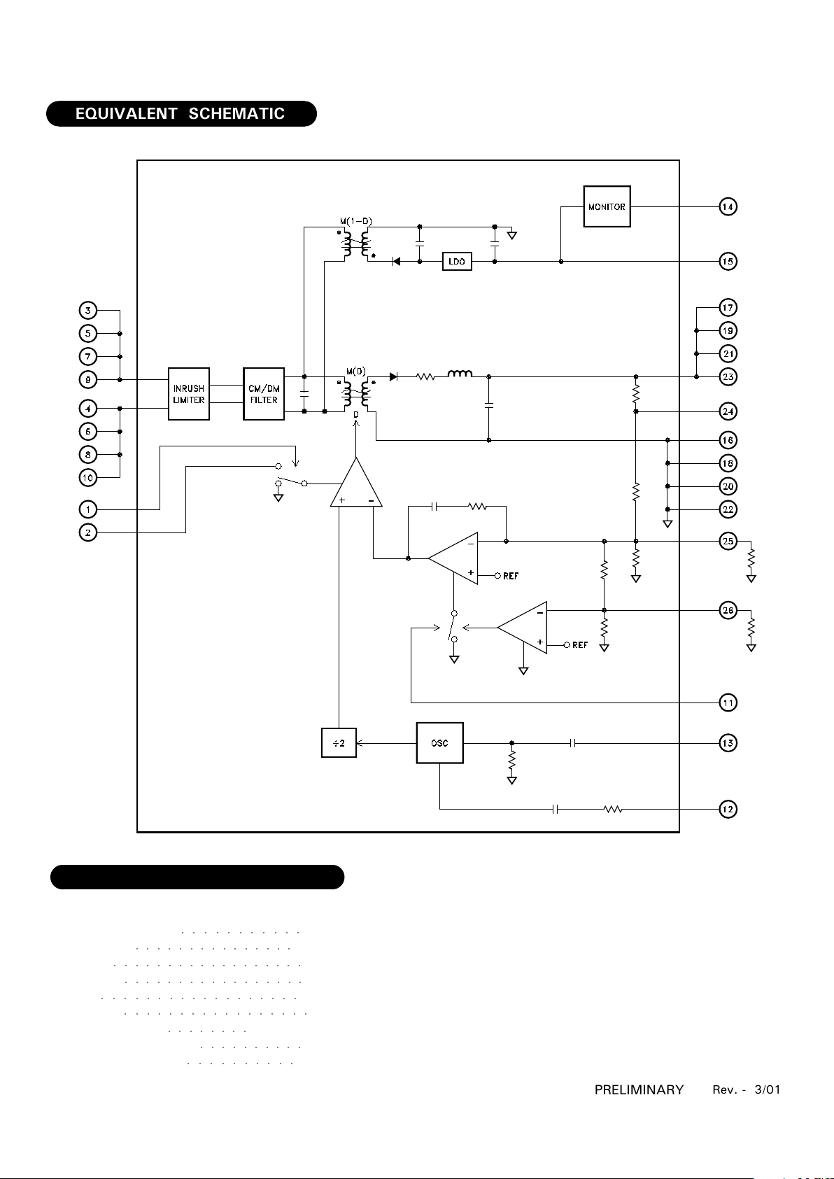
The ISR2800D utilizes two DC-DC converters to optimize power conversion efficiency and facilitate voltage sequenc-
ing necessary to protect T/R modules during power-up and power-down. A small flyback converter, referenced to
input return and switching at 200kHz, is used to provide electrical input-output isolation, generate nominal +10VDC
bias voltages for the input and output control circuits of the power supply, and generate a nominal -5VDC negative
output voltage for the T/R modules. The negative output voltage for the T/R modules is cross-regulated via a tap on
the flyback transformer and referenced to output return. A low drop-out (LDO) linear regulator is then used to further
post-regulate this output voltage to ensure tight regulation and low ripple, typically less than 5mVp-p. A single
transistor forward converter, referenced to output return and switching at 100kHz, provides the positive adjustable
output voltage. They are enclosed in a hermetic Silicon Aluminum (SiAl) package and weigh less than TBD grams.
The package utilizes rugged ceramic feed-through Glid-Cop pins and is sealed using parallel seam welding.
FEATURES:
82.5W Output Power
18-40VDC Steady-state Input Voltage Range
Adjustable Positive Output Voltage - 3.3V to 5.0V
Fixed -5V Negative Output
Typical 90% Efficiency from Half Load to Full Load
Total Dose - 100krad(Si)(max)
Single-Event Effects - LET>82MeV-cm²/mg
SEGR Hardened MOSFETs
Integrated Circuits are SEL Immune
Internal EMI Filter meets MIL-STD-461
Input Inrush Current Limiting
Remote Sense for Main Output Voltage
Soft-start Circuitry Prevents Output Voltage Overshoot
Input Undervoltage Lockout
Output Overload and Short Circuit Protection
Output Overvoltage Protection
Synchronization Capability
External Inhibit
1
Rev. - 3/01
PRELIMINARY
TYPICAL APPLICATIONS
Geostationary (GEO) Earth Orbit Satellites
Low Earth Orbit (LEO) Satellites
Deep Space Satellites/Probes
Communication Systems
PIN-OUT INFORMATION
CROW BAR
-5V OUT
VOUT RTN
+VOUT
VOUT RTN
+VOUT
VOUT RTN
+VOUT
VOUT RTN
+VOUT
REM SENSE
VOUT ADJ
VOUT OVP ADJ
PRI INHIBIT
ETERM
INPUT
INPUT RTN
INPUT
INPUT RTN
INPUT
INPUT RTN
INPUT
INPUT RTN
SEC ON/OFF
SYNC OUT
SYNC IN
1
2
3
4
5
6
7
8
9
10
11
12
13
14
15
16
17
18
19
20
21
22
23
24
25
26
2
-0.5V to +50V
Internally Limited
-0.5V to +50V
-0.5V to +50V
-0.5V to +5.0V
+Vout ±0.5V
+300°C for 10 seconds
-55°C to 85°C
-55°C to 150°C
Input Voltage Range
Ouput Power
PRI Inhibit
Sec On/Off
Sync In
Rem Sense
Lead Temperature
Operating Temperature
Storage Temperature
ABSOLUTE MAXIMUM RATINGS
○○○○○○○○○○○
○○○○○○○○○○○○○○○
○○○○○○○○○○
○○○○○○○○
○○○○○○○○○○
Rev. - 3/01
PRELIMINARY
EQUIVALENT SCHEMATIC
○○○○○○○○○○○○○○○○○
○○○○○○○○○○○○○○○○○○
○○○○○○○○○○○○○○○○○
○○○○○○○○○○○○○○○○○○
3
INPUT CHARACTERISTICS
Input Voltage
Input Voltage
-5VOUT
Output Converter Frequency
Output Voltage
Output Current
Output Power
Output Ripple
Output Current Limit
Output Over-voltage Limit
+VOUT
Output Converter Frequency
Output Voltage Adjustable Range
Output Voltage Regulation
Output Current
Output Power
Output Ripple
Output Current Limit
Output Over-voltage Limit
Output Step-load Response
Output Step-line Response
Output Step-line Recovery Time
Output Efficiency
+VOUT
Power Supply Efficiency
TURN-ON RESPONSE
-5VOUT Output Overshoot
-5VOUT Output Turn-on Time
+VOUT Overshoot
+VOUT Turn-on Time
Max.
40
50
240
-4.75
500
2.5
10
1.75
-5.50
115
5.00
5.0
-
80
1.0
24.0
130
1.6
1.6
50
-
-
-
200
-
500
Typ.
28
-
200
-5.00
200
1
5
1.50
-6.00
100
-
0.0
-
-
0.4
21.3
120
0.8
0.8
-
90
89
0
-
0
-
Min.
18
-0.5
160
-5.25
-
-
-
1.25
-6.50
85
3.30
-5.0
16
-
-
16.0
110
-1.6
-1.6
-
86
85
-
-
-
-
V
V
KHz
V
mA
W
mVp-p
A
V
KHz
V
%Vo
A
W
%Vo-p-p
A
%Vo
%Vo-p
%Vo-p
uS
%
%
mV
mS
mV
mS
Steady-state
Transient, ≤ 50ms
Zero Load to/from Half Load, VIN=22-40VDC
Zero Load to/from Half Load, VIN=22-40VDC
Recovery to within ±1% of VOUT
18V to/from 40V
18V to/from 40V, Recovery to within 1% of VOUT
+VOUT=5V, IOUT=8-16A; -IOUT=-200mA
+VOUT=5V, IOUT=16A; -IOUT=-500mA
Input Voltage Stepped from 0 to 28VDC
Parameter
Units
ISR2800D
Test Conditions
Group A
Subgroup
1,2,3
1,2,3
4,5,6
1,2,3
1,2,3
1,2,3
4,5,6
1,2,3
1,2,3
4,5,6
1,2,3
1,2,3
1,2,3
1,2,3
4,5,6
1,2,3
1,2,3
4,5,6
4,5,6
4,5,6
1,2,3
1,2,3
-
4,5,6
-
4,5,6
ELECTRICAL SPECIFICATIONS
Rev. A 10/99
PRELIMINARY
Output Step-load Recovery Time
4,5,6
Continued on next page
-
-50
uS
1
4
5
2
3
2
3
2
2
2
3
3
3
3
3
3
3
 Loading...