

Page 1

Z87-G43
H87-G43
B85-G43
Motherboard
Preface
G52-78161X3
Page 2

Preface
Copyright Notice
The material in this document is the intellectual property of MICRO-STAR
INTERNATIONAL. We take every care in the preparation of this document, but no
guarantee is given as to the correctness of its contents. Our products are under
continual improvement and we reserve the right to make changes without notice.
Trademarks
All trademarks in this manual are properties of their respective owners.
MSI® is registered trademark of Micro-Star Int’l Co.,Ltd.
■
NVIDIA® is registered trademark of NVIDIA Corporation.
■
ATI® is registered trademark of AMD Corporation.
■
AMD® is registered trademarks of AMD Corporation.
■
Intel® is registered trademarks of Intel Corporation.
■
Windows® is registered trademarks of Microsoft Corporation.
■
AMI® is registered trademark of American Megatrends Inc.
■
Award® is a registered trademark of Phoenix Technologies Ltd.
■
Sound Blaster® is registered trademark of Creative Technology Ltd.
■
Realtek® is registered trademark of Realtek Semiconductor Corporation.
■
JMicron® is registered trademark of JMicron Technology Corporation.
■
Netware® is registered trademark of Novell, Inc.
■
Lucid® is trademark of LucidLogix Technologies, Ltd.
■
VIA® is registered trademark of VIA Technologies, Inc.
■
ASMedia® is registered trademark of ASMedia Technology Inc.
■
iPad, iPhone, and iPod are trademarks of Apple Inc.
■
Qualcomm Atheros and Killer are trademarks of Qualcomm Atheros Inc.
■
Revision History
Revision Revision History Date
V1.0 First release 2013/ 04
iiPreface
Page 3
Smartphone Application
MSI+ is a smart web gadget that works as a shopping navigator and
provides specs comparison for IT buyers. With a simple tap of the
smartphone, you'll eciently locate your ideal products from a wide
variety of choices and, if product details are required, you may easily
download user manuals within minutes. Better yet, the power calculator
provides accurate estimates of power unit capacity for DIY users.
Technical Support
If a problem arises with your system and no solution can be obtained from the user’s
manual, please contact your place of purchase or local distributor. Alternatively,
please try the following help resources for further guidance.
Preface
Visit the MSI website for technical guide, BIOS
updates, driver updates, and other information:
http://www.msi.com/service/download/
Contact our technical sta at:
http://support.msi.com
iii Preface
Page 4

Preface
Safety Instructions
Always read the safety instructions carefully.
■
Keep this User’s Manual for future reference.
■
Keep this equipment away from humidity.
■
Lay this equipment on a reliable at surface before setting it up.
■
The openings on the enclosure are for air convection hence protects the equipment
■
from overheating. DO NOT COVER THE OPENINGS.
Make sure the voltage of the power source is at 110/220V before connecting the
■
equipment to the power inlet.
Place the power cord such a way that people can not step on it. Do not place
■
anything over the power cord.
Always Unplug the Power Cord before inserting any add-on card or module.
■
All cautions and warnings on the equipment should be noted.
■
Never pour any liquid into the opening that can cause damage or cause electrical
■
shock.
If any of the following situations arises, get the equipment checked by service
■
personnel:
The power cord or plug is damaged.
◯
Liquid has penetrated into the equipment.
◯
The equipment has been exposed to moisture.
◯
The equipment does not work well or you can not get it work according to
◯
User’s Manual.
The equipment has been dropped and damaged.
◯
The equipment has obvious sign of breakage.
◯
DO NOT LEAVE THIS EQUIPMENT IN AN ENVIRONMENT ABOVE 60oC (140oF),
■
IT MAY DAMAGE THE EQUIPMENT.
ivPreface
Page 5
FCC-B Radio Frequency Interference Statement
This equipment has been tested and found to comply with the limits for a Class B
digital device, pursuant to Part 15 of the FCC Rules. These limits are designed to
provide reasonable protection against harmful interference in a residential installation.
This equipment generates, uses and can radiate radio frequency energy and, if not
installed and used in accordance with the instructions, may cause harmful interference
to radio communications. However, there is no guarantee that interference will not
occur in a particular installation. If this equipment does cause harmful interference to
radio or television reception, which can be determined by turning the equipment o
and on, the user is encouraged to try to correct the interference by one or more of the
measures listed below.
Reorient or relocate the receiving antenna.
◯
Increase the separation between the equipment and receiver.
◯
Connect the equipment into an outlet on a circuit dierent from that to which
◯
the receiver is connected.
Consult the dealer or an experienced radio/television technician for help.
◯
Notice 1
The changes or modications not expressly approved by the party responsible for
compliance could void the user’s authority to operate the equipment.
Notice 2
Shielded interface cables and A.C. power cord, if any, must be used in order to comply
with the emission limits.
VOIR LA NOTICE D’INSTALLATION AVANT DE RACCORDER AU RESEAU.
Micro-Star International
MS-7816
Preface
This device complies with Part 15 of the FCC Rules. Operation is subject to the
following two conditions:
this device may not cause harmful interference, and
1)
this device must accept any interference received, including interference that may
2)
cause undesired operation.
CE Conformity
Hereby, Micro-Star International CO., LTD declares that this device is
in compliance with the essential safety requirements and other relevant
provisions set out in the European Directive.
v Preface
Page 6

Preface
Radiation Exposure Statement
This equipment complies with FCC radiation exposure limits set forth for an
uncontrolled environment. This equipment and its antenna should be installed and
operated with minimum distance 20 cm between the radiator and your body. This
equipment and its antenna must not be co-located or operating in conjunction with any
other antenna or transmitter.
European Community Compliance Statement
The equipment complies with the RF Exposure Requirement 1999/519/EC, Council
Recommendation of 12 July 1999 on the limitation of exposure of the general public
to electromagnetic elds (0–300GHz). This wireless device complies with the R&TTE
Directive.
Taiwan Wireless Statements
無線設備警告聲明
經型式認證合格之低功率射頻電機,非經許可,公司、商號或使用者均不得擅自變更頻
率、加大功率或變更原設計之特性及功能。
低功率射頻電機之使用不得影響飛航安全及干擾合法通信;經發現有干擾現象時,應立
即停用,並改善至無干擾時方得繼續使用。前項合法通信,指依電信法規定作業之無線
電通信。低功率射頻電機須忍受合法通信或工業、科學及醫療用電波輻射性電機設備之
干擾。
警告使用者:這是甲類資訊產品,在居住的環境中使用時,可能會造成無線電干擾,在
這種情況下,使用者會被要求採取某些適當的對策。
Japan VCCI Class B Statement
クラス B 情報技術装置
この装置は、情報技術装置等電波障害自主規制協議会(VCCI)の基準に基づくクラ
スB情報技術装置です。この装置が家庭内でラジオやテレビジョン受信機に近接して
使われると、受信障害を引き起こすことがあります。取扱説明書にしたがって正しい
取り扱いをしてください。
Korea Warning Statements
당해 무선설비는 운용중 전파혼신 가능성이 있음
viPreface
Page 7
Battery Information
European Union:
Batteries, battery packs, and accumulators should not be disposed of
as unsorted household waste. Please use the public collection system
to return, recycle, or treat them in compliance with the local regulations.
Taiwan:
For better environmental protection, waste batteries should be collected
separately for recycling or special disposal.
廢電池請回收
California, USA:
The button cell battery may contain perchlorate material and requires
special handling when recycled or disposed of in California.
For further information please visit:
http://www.dtsc.ca.gov/hazardouswaste/perchlorate/
CAUTION: There is a risk of explosion, if battery is incorrectly replaced.
Replace only with the same or equivalent type recommended by the manufacturer.
Chemical Substances Information
In compliance with chemical substances regulations, such as the EU REACH
Regulation (Regulation EC No. 1907/2006 of the European Parliament and the
Council), MSI provides the information of chemical substances in products at:
http://www.msi.com/html/popup/csr/evmtprtt_pcm.html
Preface
vii Preface
Page 8
WEEE (Waste Electrical and Electronic Equipment) Statement
Preface
ENGLISH
To protect the global environment and as an environmentalist, MSI must
remind you that...
Under the European Union (“EU”) Directive on Waste Electrical and
Electronic Equipment, Directive 2002/96/EC, which takes eect on August
13, 2005, products of “electrical and electronic equipment” cannot be
discarded as municipal wastes anymore, and manufacturers of covered
electronic equipment will be obligated to take back such products at the end of their
useful life. MSI will comply with the product take back requirements at the end of life
of MSI-branded products that are sold into the EU. You can return these products to
local collection points.
DEUTSCH
Hinweis von MSI zur Erhaltung und Schutz unserer Umwelt
Gemäß der Richtlinie 2002/96/EG über Elektro- und Elektronik-Altgeräte dürfen
Elektro- und Elektronik-Altgeräte nicht mehr als kommunale Abfälle entsorgt werden.
MSI hat europaweit verschiedene Sammel- und Recyclingunternehmen beauftragt,
die in die Europäische Union in Verkehr gebrachten Produkte, am Ende seines
Lebenszyklus zurückzunehmen. Bitte entsorgen Sie dieses Produkt zum gegebenen
Zeitpunkt ausschliesslich an einer lokalen Altgerätesammelstelle in Ihrer Nähe.
FRANÇAIS
En tant qu’écologiste et an de protéger l’environnement, MSI tient à rappeler ceci...
Au sujet de la directive européenne (EU) relative aux déchets des équipement
électriques et électroniques, directive 2002/96/EC, prenant eet le 13 août 2005,
que les produits électriques et électroniques ne peuvent être déposés dans les
décharges ou tout simplement mis à la poubelle. Les fabricants de ces équipements
seront obligés de récupérer certains produits en n de vie. MSI prendra en compte
cette exigence relative au retour des produits en n de vie au sein de la communauté
européenne. Par conséquent vous pouvez retourner localement ces matériels dans
les points de collecte.
РУССКИЙ
Компания MSI предпринимает активные действия по защите окружающей среды,
поэтому напоминаем вам, что....
В соответствии с директивой Европейского Союза (ЕС) по предотвращению
загрязнения окружающей среды использованным электрическим и электронным
оборудованием (директива WEEE 2002/96/EC), вступающей в силу 13
августа 2005 года, изделия, относящиеся к электрическому и электронному
оборудованию, не могут рассматриваться как бытовой мусор, поэтому
производители вышеперечисленного электронного оборудования обязаны
принимать его для переработки по окончании срока службы. MSI обязуется
соблюдать требования по приему продукции, проданной под маркой MSI на
территории EC, в переработку по окончании срока службы. Вы можете вернуть
эти изделия в специализированные пункты приема.
viiiPreface
Page 9

ESPAÑOL
MSI como empresa comprometida con la protección del medio ambiente, recomienda:
Bajo la directiva 2002/96/EC de la Unión Europea en materia de desechos y/o
equipos electrónicos, con fecha de rigor desde el 13 de agosto de 2005, los productos
clasicados como “eléctricos y equipos electrónicos” no pueden ser depositados en
los contenedores habituales de su municipio, los fabricantes de equipos electrónicos,
están obligados a hacerse cargo de dichos productos al termino de su período de
vida. MSI estará comprometido con los términos de recogida de sus productos
vendidos en la Unión Europea al nal de su periodo de vida. Usted debe depositar
estos productos en el punto limpio establecido por el ayuntamiento de su localidad o
entregar a una empresa autorizada para la recogida de estos residuos.
NEDERLANDS
Om het milieu te beschermen, wil MSI u eraan herinneren dat….
De richtlijn van de Europese Unie (EU) met betrekking tot Vervuiling van Electrische
en Electronische producten (2002/96/EC), die op 13 Augustus 2005 in zal gaan
kunnen niet meer beschouwd worden als vervuiling. Fabrikanten van dit soort
producten worden verplicht om producten retour te nemen aan het eind van hun
levenscyclus. MSI zal overeenkomstig de richtlijn handelen voor de producten
die de merknaam MSI dragen en verkocht zijn in de EU. Deze goederen kunnen
geretourneerd worden op lokale inzamelingspunten.
SRPSKI
Da bi zaštitili prirodnu sredinu, i kao preduzeće koje vodi računa o okolini i prirodnoj
sredini, MSI mora da vas podesti da…
Po Direktivi Evropske unije (“EU”) o odbačenoj ekektronskoj i električnoj opremi,
Direktiva 2002/96/EC, koja stupa na snagu od 13. Avgusta 2005, proizvodi koji
spadaju pod “elektronsku i električnu opremu” ne mogu više biti odbačeni kao običan
otpad i proizvođači ove opreme biće prinuđeni da uzmu natrag ove proizvode na kraju
njihovog uobičajenog veka trajanja. MSI će poštovati zahtev o preuzimanju ovakvih
proizvoda kojima je istekao vek trajanja, koji imaju MSI oznaku i koji su prodati u EU.
Ove proizvode možete vratiti na lokalnim mestima za prikupljanje.
Preface
POLSKI
Aby chronić nasze środowisko naturalne oraz jako rma dbająca o ekologię, MSI
przypomina, że...
Zgodnie z Dyrektywą Unii Europejskiej (“UE”) dotyczącą odpadów produktów
elektrycznych i elektronicznych (Dyrektywa 2002/96/EC), która wchodzi w życie 13
sierpnia 2005, tzw. “produkty oraz wyposażenie elektryczne i elektroniczne “ nie
mogą być traktowane jako śmieci komunalne, tak więc producenci tych produktów
będą zobowiązani do odbierania ich w momencie gdy produkt jest wycofywany z
użycia. MSI wypełni wymagania UE, przyjmując produkty (sprzedawane na terenie
Unii Europejskiej) wycofywane z użycia. Produkty MSI będzie można zwracać w
wyznaczonych punktach zbiorczych.
ix Preface
Page 10

Preface
TÜRKÇE
Çevreci özelliğiyle bilinen MSI dünyada çevreyi korumak için hatırlatır:
Avrupa Birliği (AB) Kararnamesi Elektrik ve Elektronik Malzeme Atığı, 2002/96/EC
Kararnamesi altında 13 Ağustos 2005 tarihinden itibaren geçerli olmak üzere,
elektrikli ve elektronik malzemeler diğer atıklar gibi çöpe atılamayacak ve bu elektonik
cihazların üreticileri, cihazların kullanım süreleri bittikten sonra ürünleri geri toplamakla
yükümlü olacaktır. Avrupa Birliği’ne satılan MSI markalı ürünlerin kullanım süreleri
bittiğinde MSI ürünlerin geri alınması isteği ile işbirliği içerisinde olacaktır. Ürünlerinizi
yerel toplama noktalarına bırakabilirsiniz.
ČESKY
Záleží nám na ochraně životního prostředí - společnost MSI upozorňuje...
Podle směrnice Evropské unie (“EU”) o likvidaci elektrických a elektronických výrobků
2002/96/EC platné od 13. srpna 2005 je zakázáno likvidovat “elektrické a elektronické
výrobky” v běžném komunálním odpadu a výrobci elektronických výrobků, na které
se tato směrnice vztahuje, budou povinni odebírat takové výrobky zpět po skončení
jejich životnosti. Společnost MSI splní požadavky na odebírání výrobků značky
MSI, prodávaných v zemích EU, po skončení jejich životnosti. Tyto výrobky můžete
odevzdat v místních sběrnách.
MAGYAR
Annak érdekében, hogy környezetünket megvédjük, illetve környezetvédőként fellépve
az MSI emlékezteti Önt, hogy ...
Az Európai Unió („EU”) 2005. augusztus 13-án hatályba lépő, az elektromos
és elektronikus berendezések hulladékairól szóló 2002/96/EK irányelve szerint
az elektromos és elektronikus berendezések többé nem kezelhetőek lakossági
hulladékként, és az ilyen elektronikus berendezések gyártói kötelessé válnak az
ilyen termékek visszavételére azok hasznos élettartama végén. Az MSI betartja a
termékvisszavétellel kapcsolatos követelményeket az MSI márkanév alatt az EU-n
belül értékesített termékek esetében, azok élettartamának végén. Az ilyen termékeket
a legközelebbi gyűjtőhelyre viheti.
ITALIANO
Per proteggere l’ambiente, MSI, da sempre amica della natura, ti ricorda che….
In base alla Direttiva dell’Unione Europea (EU) sullo Smaltimento dei Materiali Elettrici
ed Elettronici, Direttiva 2002/96/EC in vigore dal 13 Agosto 2005, prodotti appartenenti
alla categoria dei Materiali Elettrici ed Elettronici non possono più essere eliminati
come riuti municipali: i produttori di detti materiali saranno obbligati a ritirare ogni
prodotto alla ne del suo ciclo di vita. MSI si adeguerà a tale Direttiva ritirando tutti i
prodotti marchiati MSI che sono stati venduti all’interno dell’Unione Europea alla ne
del loro ciclo di vita. È possibile portare i prodotti nel più vicino punto di raccolta
xPreface
Page 11
CONTENTS
▍
English ...................................................................................................... En-1
Motherboard Specications ................................................................................En-2
Connectors Quick Guide ....................................................................................En-5
Back Panel Quick Guide ....................................................................................En-7
CPU (Central Processing Unit) ..........................................................................En-9
Memory ............................................................................................................En-13
Mounting Screw Holes .....................................................................................En-14
Power Supply ...................................................................................................En-15
Expansion Slots ...............................................................................................En-16
Video/ Graphics Cards ....................................................................................En-17
Internal Connectors ..........................................................................................En-18
Jumper .............................................................................................................En-25
Drivers and Utilities ..........................................................................................En-26
BIOS Setup ......................................................................................................En-27
Deutsch ....................................................................................................De-1
Spezikationen .................................................................................................. De-2
Anschlussübersicht ........................................................................................... De-5
Rücktafel-Übersicht ........................................................................................... De-7
CPU (Prozessor) ............................................................................................... De-9
Speicher .......................................................................................................... De-13
Schraubenlöcher für die Montage ................................................................... De-14
Stromversorgung ............................................................................................. De-15
Erweiterungssteckplätze ................................................................................. De-16
Video/ Grakkarten ........................................................................................ De-17
Interne Anschlüsse .......................................................................................... De-18
Steckbrücken .................................................................................................. De-25
Treiber und Dienstprogramme ........................................................................ De-26
BIOS Setup ..................................................................................................... De-27
Français ..................................................................................................... Fr-1
Spécications ......................................................................................................Fr-2
Guide Rapide Des Connecteurs .........................................................................Fr-5
Guide rapide du panneau arrière ........................................................................Fr-7
Processeur : CPU ...............................................................................................Fr-9
Mémoire ............................................................................................................Fr-13
Trous Taraudés de Montage .............................................................................Fr-14
Connecteurs d’alimentation ...............................................................................Fr-15
Emplacements d’extension ...............................................................................Fr-16
Preface
xi Preface
Page 12

Preface
Cartes Vidéo/ Graphics ....................................................................................Fr-17
Connecteurs internes ........................................................................................Fr-18
Cavaliers ...........................................................................................................Fr-25
Pilotes et Utilitaires ............................................................................................Fr-26
Conguration BIOS ...........................................................................................Fr-27
Русский ....................................................................................................Ru-1
Характеристики системной платы.................................................................. Ru-2
Краткое руководство по разъемам ................................................................ Ru-5
Краткое руководство по работе с задней панелью ...................................... Ru-7
ЦП (центральный процессор) ......................................................................... Ru-9
Память ............................................................................................................ Ru-13
Отверстия под установочные винты ............................................................ Ru-14
Электропитание ............................................................................................. Ru-15
Слоты расширения ........................................................................................ Ru-16
Видео/ Установка дискретной видеокарты ................................................ Ru-17
Внутренние разъемы .................................................................................... Ru-18
Перемычки ..................................................................................................... Ru-25
Драйверы и утилиты ..................................................................................... Ru-26
Настройка BIOS ............................................................................................. Ru-27
Installation/ Установка ............................................................................... A-1
CPU ......................................................................................................................A-2
Memory/ Speicher/ Mémoire/ Памяти .................................................................A-4
Motherboard/ Carte mère/ Материнские платы .................................................A-5
Power Connector/ ATX-Stromanshcluss/ Connecteurs d'alimentation/ Pазъема
питания ................................................................................................................A-7
SATA HDD ...........................................................................................................A-9
mSATA SSD ......................................................................................................A-10
Front Panel Connector/ Frontpanel Anschluss/ Connecteur panneau avant/
Pазъемов передней панели ............................................................................A-11
Peripheral Connector/ Peripheriestecker/ Connecteur périphérique/ Периферийных
разъемов ...........................................................................................................A-12
Graphics Card/ Grakkarte/ Carte graphique/ Bидеокарты ..............................A-13
xiiPreface
Page 13

English
Thank you for choosing the Z87-G43/ H87-G43/ B85-G43 Series (MS7816 v1.X) ATX motherboard. The Z87-G43/ H87-G43/ B85-G43 Series
motherboards are based on Intel® Z87/ H87/ B85 chipset for optimal system
eciency. Designed to t the advanced Intel® LGA1150 processor, the Z87G43/ H87-G43/ B85-G43 Series motherboards deliver a high performance
and professional desktop platform solution.
Page 14
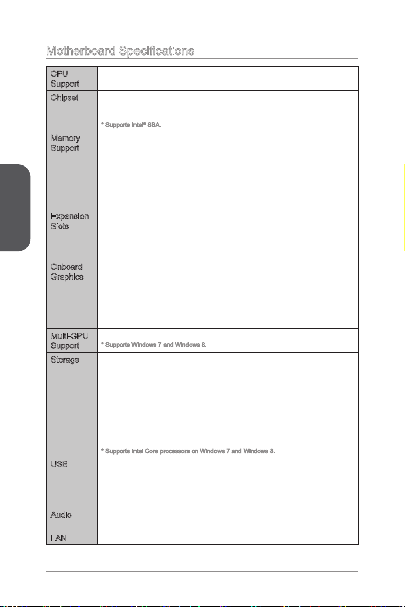
Motherboard Specications
English
CPU
Support
Chipset Intel® Z87 Express Chipset (Z87-G43)
Memory
Support
Expansion
Slots
Onboard
Graphics
Multi-GPU
Support
Storage Intel Z87/ H87/ B85 Express Chipset
USB Intel Z87/ H87/ B85 Express Chipset
Audio Realtek® ALC892 Codec
LAN 1x Realtek® 8111E Gigabit LAN controller■
4th Generation Intel® Core™ i7 / Core™ i5 / Core™ i3 / Pentium® /
■
Celeron® processors for LGA 1150 socket
■
Intel® H87 Express Chipset (H87-G43)*
■
Intel® B85 Express Chipset (B85-G43)*
■
* Supports Intel® SBA.
4x DDR3 memory slots supporting up to 32GB
■
Supports DDR3 3000(OC)/ 2800(OC)/ 2666(OC)/ 2600(OC)/
■
2400(OC)/ 2200(OC)/ 2133(OC)/ 2000(OC)/ 1866(OC)/ 1600/ 1333/
1066 MHz
OC is for Z87-G43 only.
-
Dual channel memory architecture
■
Supports non-ECC, un-buered memory
■
Supports Intel® Extreme Memory Prole (XMP)
■
1x PCIe 3.0 x16 slot
■
1x PCIe 2.0 x16 slot
■
Supports up to PCIe 2.0 x4 speed.
-
2x PCIe 2.0 x1 slots
■
3x PCI slots
■
1x VGA port, supporting a maximum resolution of 1920x1200 @
■
60Hz
1x HDMI® port, supporting a maximum resolution of
■
4096x2160@24Hz, 24bpp/ 2560x1600@60Hz, 24bpp/
1920x1080@60Hz, 36bpp
1x DVI-D port, supporting a maximum resolution of 1920x1200 @
■
60Hz
Supports 2-Way AMD CrossFireTM Technology*
■
* Supports Windows 7 and Windows 8.
■
6x SATA 6Gb/s ports (SATA1~6) (Z87-G43/ H87-G43)
4x SATA 6Gb/s ports (SATA1~4) (B85-G43)
2x SATA 3Gb/s ports (SATA5~6) (B85-G43)
Supports RAID 0, RAID1, RAID 5 and RAID 10 (For Z87-G43/
H87-G43)
Supports Intel Smart Response Technology* (Z87-G43 and H87-
G43)
Supports Intel Rapid Start Technology and Intel Smart Connect
Technology*
* Supports Intel Core processors on Windows 7 and Windows 8.
■
4x USB 3.0 ports (2 ports on the back panel, 2 ports available
through the internal USB connectors)
10x USB 2.0 ports (6 ports on the back panel, 4 ports available
through the internal USB connectors)
■
7.1-Channel High Denition Audio
-
En-2
Page 15
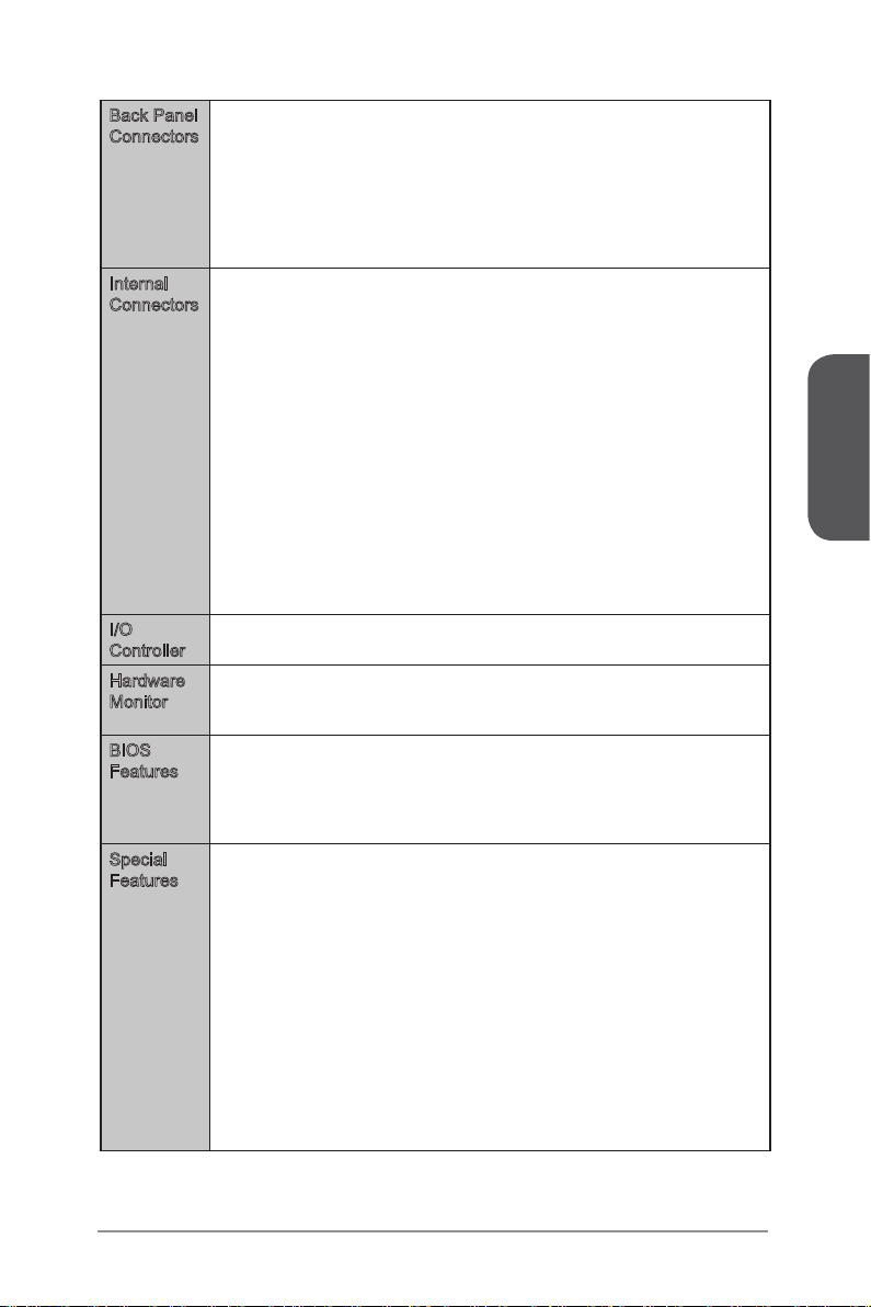
Back Panel
Connectors
Internal
Connectors
I/O
Controller
Hardware
Monitor
BIOS
Features
Special
Features
1x PS/2 keyboard/ mouse combo port
■
6x USB 2.0 ports
■
1x HDMI port
■
1x VGA port
■
1x DVI-D port
■
1x LAN (RJ45) port
■
2x USB 3.0 ports
■
6x audio jacks
■
1x 24-pin ATX main power connector
■
1x 8-pin ATX 12V power connector
■
6x SATA 6Gb/s connectors
■
For Z87-G43/ H87-G43.
-
4x SATA 6Gb/s connectors and 2x SATA 3Gb/s connectors
■
For B85-G43.
-
2x USB 2.0 connectors (supports additional 4 USB 2.0 ports)
■
1x USB 3.0 connectors (supports additional 2 USB 3.0 ports)
■
2x 4-pin CPU fan connectors
■
3x 4-pin system fan connectors
■
1x Clear CMOS jumper
■
1x Front panel audio connector
■
2x System panel connectors
■
1x TPM module connector
■
1x Serial port connector
■
1x Parallel port connector
■
1x Chassis Intrusion connector
■
NUVOTON NCT6779 Controller Chip■
CPU/System temperature detection
■
CPU/System fan speed detection
■
CPU/System fan speed control
■
64 Mb ash (Z87-G43)
■
128 Mb ash (H87-G43/ B85-G43)
■
UEFI AMI BIOS
■
ACPI 5.0, PnP 1.0a, SM BIOS 2.7, DMI 2.0
■
Multi-language
■
DigitALL Power
■
Military Class 4
■
OC Genie 4
■
CLICK BIOS 4
■
All Solid CAPs
■
AMD CrossFire
■
PCI Express Gen 3
■
Sound Blaster Cinema (optional)
■
Super RAID
■
USB 3.0
■
SATA 6Gb/s
■
HDMI
■
Command Center
■
Live Update
■
M-Flash
■
English
En-3
Page 16
English
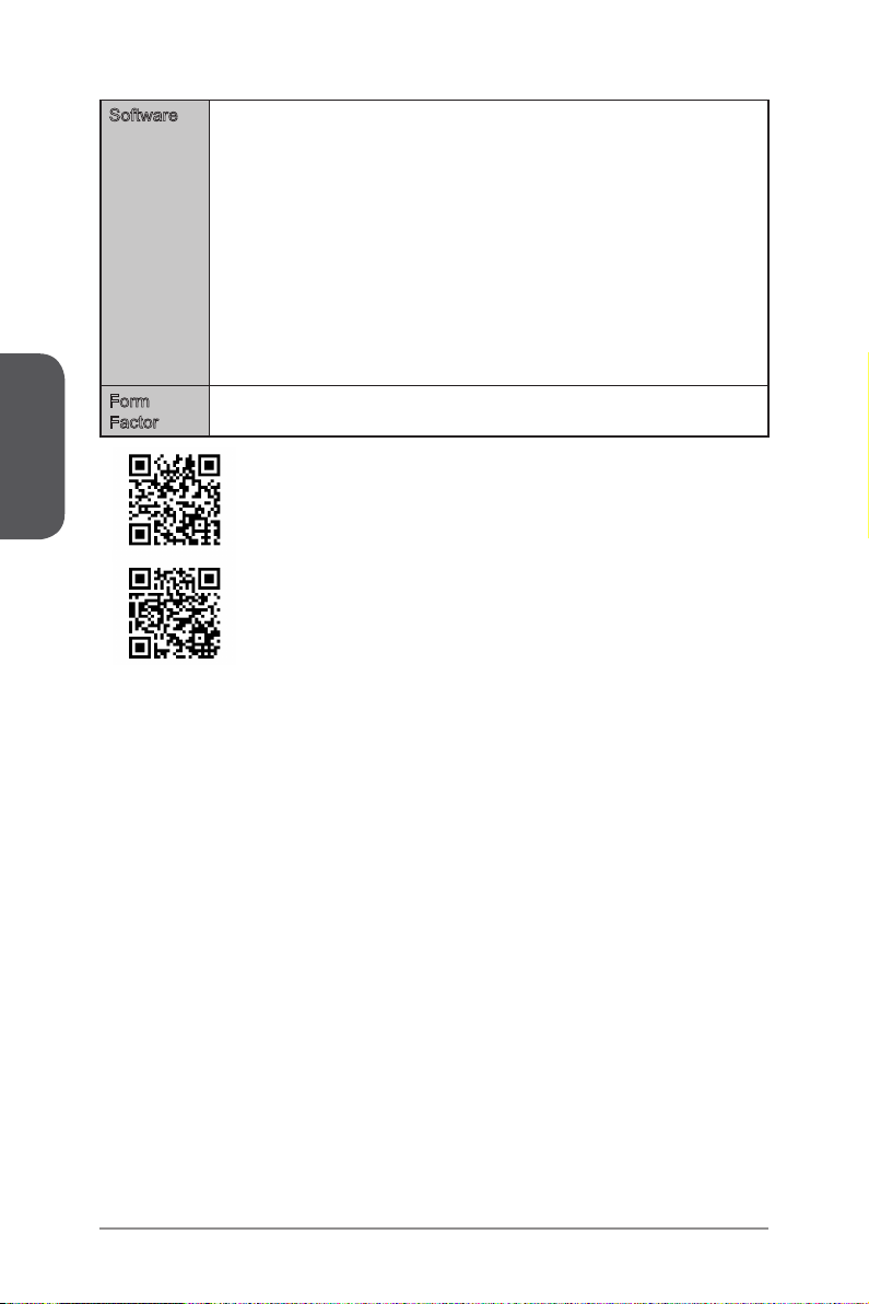
Software Drivers
Form
Factor
■
MSI
■
Command Center
Super Charger
Super RAID
Live Update 5
Fast Boot
-
7-ZIP
■
Intel Turbo Boost Monitor
■
Intel Extreme Tuning Utility
■
Intel Small Business Advantage (Optional)
■
Sound Blaster Cinema (Optional)
■
Norton Internet Security Solution
■
Trend Micro SafeSync
■
ATX Form Factor
■
12.0 in. x 9.6 in. (30.5 cm x 24.4 cm)
■
For the latest information about CPU, please visit
http://www.msi.com/service/cpu-support/
For more information on compatible components, please visit
http://www.msi.com/service/test-report/
En-4
Page 17
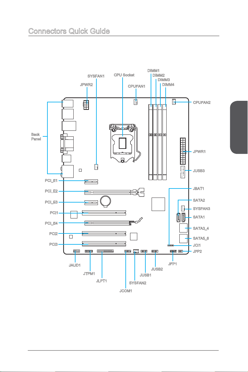
Connectors Quick Guide
Back
Panel
PCI_E1
PCI_E2
PCI_E3
PCI1
PCI_E4
PCI2
PCI3
SYSFAN1
JPWR2
CPU Socket
CPUFAN1
DIMM1
DIMM2
DIMM3
DIMM4
CPUFAN2
English
JPWR1
JUSB3
JBAT1
SATA2
SYSFAN3
SATA1
SATA3_4
SATA5_6
JCI1
JFP2
JAUD1
JTPM1
JLPT1
JFP1
JUSB2
JUSB1
SYSFAN2
JCOM1
En-5
Page 18
English
Connectors Reference Guide
Port Name Port Type Page
Back Panel I/O Ports En-7
CPU Socket LGA1150 CPU Socket En-1
CPUFAN1~2,SYSFAN1~3: Fan Power Connectors En-19
DIMM1~4 DDR3 Memory Slots En-1
JAUD1 Front Panel Audio Connector En-2
JBAT1 Clear CMOS Jumper En-2
JCI1 Chassis Intrusion Connector En-2
JCOM1 Serial Port Connector En-2
JFP1, JFP2 System Panel Connectors En-2
JLPT1 Parallel Port Connector En-2
JPWR1~2 ATX Power Connectors En-1
JTPM1 TPM Module Connector En-2
JUSB1~2 USB 2.0 Expansion Connectors En-2
JUSB3 USB 3.0 Expansion Connector En-2
PCI_E1, 3 PCIe x1 Expansion Slots En-1
PCI_E2, 4 PCIe x16 Expansion Slots En-1
PCI1~3 PCI Expansion Slots En-1
SATA1~6 SATA Connectors En-1
0
3
3
5
2
4
0
3
5
2
1
1
6
6
6
8
En-6
Page 19
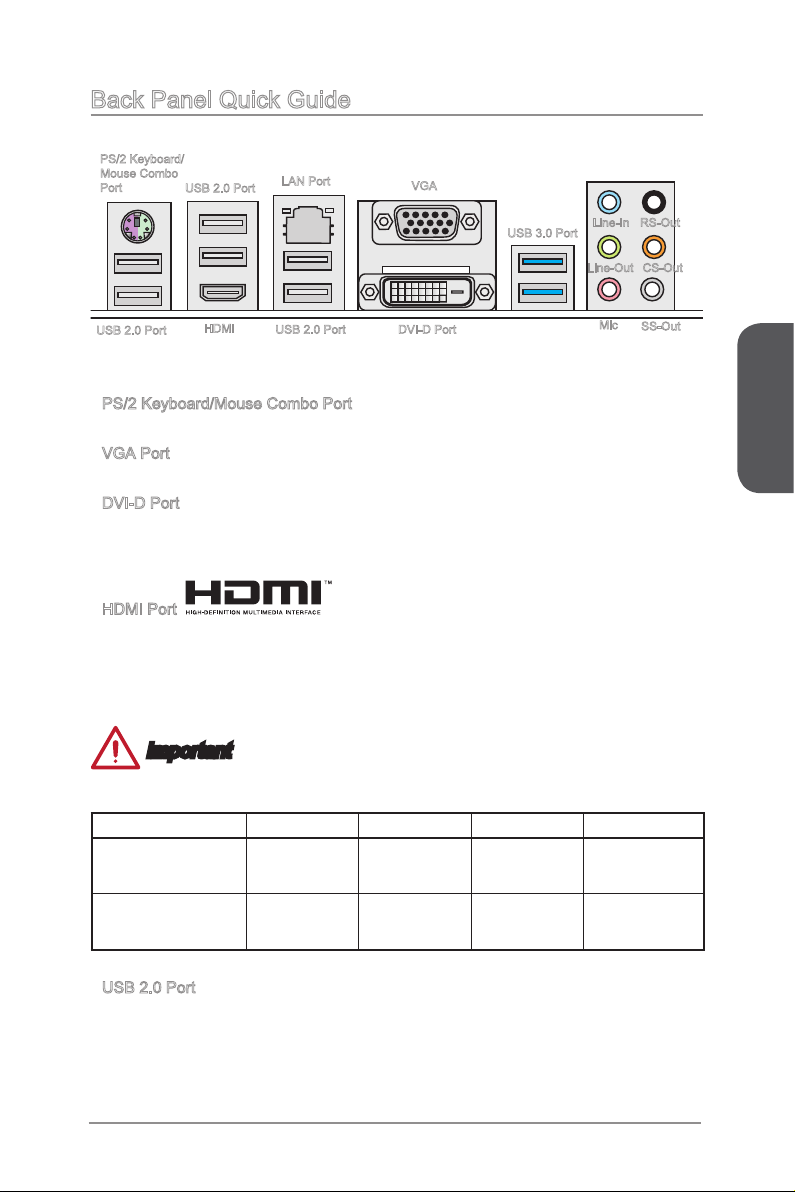
Back Panel Quick Guide
PS/2 Keyboard/
Mouse Combo
Port
USB 2.0 Port
PS/2 Keyboard/Mouse Combo Port
▶
USB 2.0 Port
HDMI
A combination of PS/2® mouse/keyboard DIN connector for a PS/2® mouse/keyboard.
VGA Port
▶
The DB15-pin female connector is provided for monitor.
▶
DVI-D Port
The DVI-D (Digital Visual Interface- Digital) connector can be connected to a LCD
monitor, or a CRT monitor with an adapter. To connect a monitor, please refer to the
monitor’s manual for more information.
HDMI Port
▶
The High-Denition Multimedia Interface (HDMI) is an all-digital audio-video interface
that is capable of transmitting uncompressed streams. HDMI supports all types of TV
formats, including standard, enhanced, or high-denition video, plus multi-channel
digital audio on a single cable.
LAN Port
USB 2.0 Port
VGA
DVI-D Port
USB 3.0 Port
Line-In
Line-Out
Mic
RS-Out
CS-Out
SS-Out
English
Important
This platform supports dual-display or triple-display function by integrated graphics
output ports.
VGA+DVI-D DVI-D+HDMI HDMI+VGA HDMI+VGA+DVI-D
Extend mode
(Extend the desktop to
the other monitors)
Clone mode
(Monitors have the same
screen)
▶
USB 2.0 Port
The USB 2.0 port is for attaching USB 2.0 devices such as keyboard, mouse, or other
USB 2.0-compatible devices.
◯ ◯ ◯ ◯
◯ ◯ ◯ ◯
En-7
Page 20
English
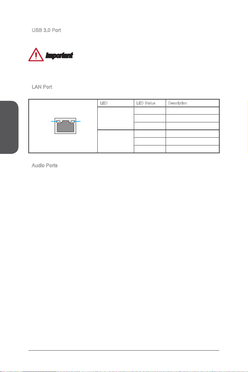
USB 3.0 Port
▶
USB 3.0 port is backward-compatible with USB 2.0 devices. It supports data transfer
rate up to 5 Gbit/s (SuperSpeed).
Important
In order to use USB 3.0 devices, you must connect to a USB 3.0 port. If a USB cable
is used, it must be USB 3.0 compliant.
LAN Port
▶
The standard RJ-45 LAN jack is for connecting to a Local Area Network (LAN).
LED LED Status Description
O No link
LINK/ACT
LED
Audio Ports
▶
SPEED
Link/ Activity LED
LED
Speed LED
These connectors are used for audio devices. The color of the jack refers to the
function of the connector.
Blue-Line in: Used for connecting external audio outputting devices.
■
Green- Line out: Used as a connector for speakers or headphone.
■
Pink- Mic: Used as a connector for a microphone.
■
Black- RS-Out: Rear surround sound line out in 4/ 5.1/ 7.1 channel mode.
■
Orange- CS-Out: Center/ subwoofer line out in 5.1/ 7.1 channel mode.
■
Gray- SS-Out: Side surround sound line out in 7.1 channel mode.
■
Yellow Linked
Blinking Data activity
O 10 Mbps connection
Green 100 Mbps connection
Orange 1 Gbps connection
En-8
Page 21
CPU (Central Processing Unit)
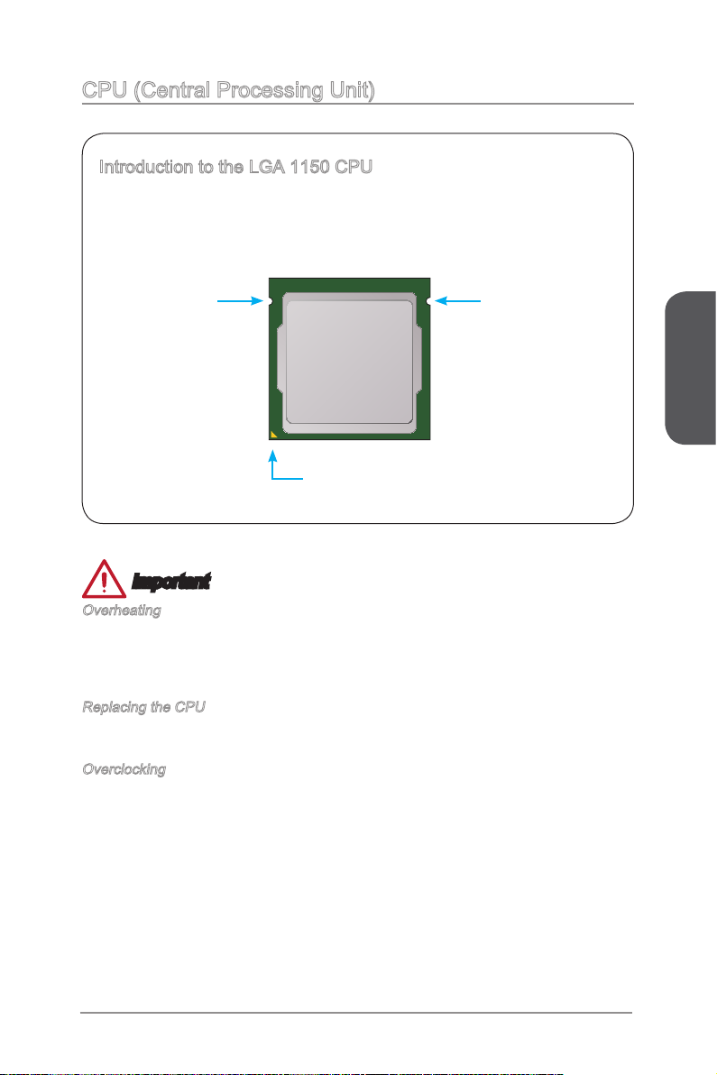
Introduction to the LGA 1150 CPU
The surface of the LGA 1150 CPU has two notches and a golden triangle to
assist in correctly lining up the CPU for motherboard placement. The golden
triangle is the Pin 1 indicator.
Notch
Golden triangle is the Pin 1 indicator
Notch
Important
Overheating
Overheating can seriously damage the CPU and motherboard. Always make sure the
cooling fans work properly to protect the CPU from overheating. Be sure to apply an
even layer of thermal paste (or thermal tape) between the CPU and the heatsink to
enhance heat dissipation.
Replacing the CPU
When replacing the CPU, always turn o the system’s power supply and unplug the
power supply’s power cord to ensure the safety of the CPU.
Overclocking
This motherboard is designed to support overclocking. Before attempting to overclock,
please make sure that all other system components can tolerate overclocking. Any
attempt to operate beyond product specications is not recommend. MSI does not
guarantee the damages or risks caused by inadequate operation beyond product
specications.
English
En-9
Page 22
English
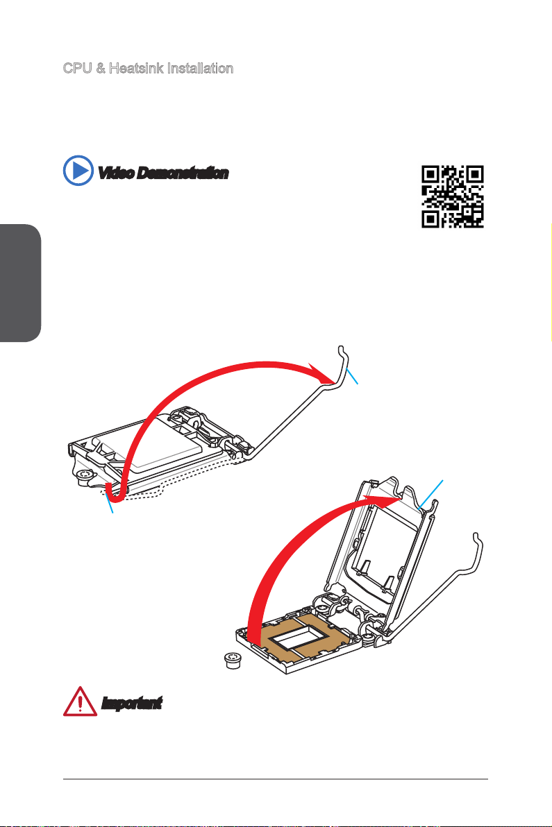
CPU & Heatsink Installation
When installing a CPU, always remember to install a CPU heatsink. A CPU heatsink
is necessary to prevent overheating and maintain system stability. Follow the steps
below to ensure correct CPU and heatsink installation. Wrong installation can damage
both the CPU and the motherboard.
Video Demonstration
Watch the video to learn how to install CPU & heatsink. at the address
below.
http://youtu.be/bf5La099urI
1. Push the load lever down to unclip it and lift to the fully open position.
2. The load plate will automatically lift up as the load lever is pushed to the fully open
position.
Load lever
Load plate
Retention tab
Important
Do not touch the socket contacts or the bottom of the CPU.
En-10
Page 23
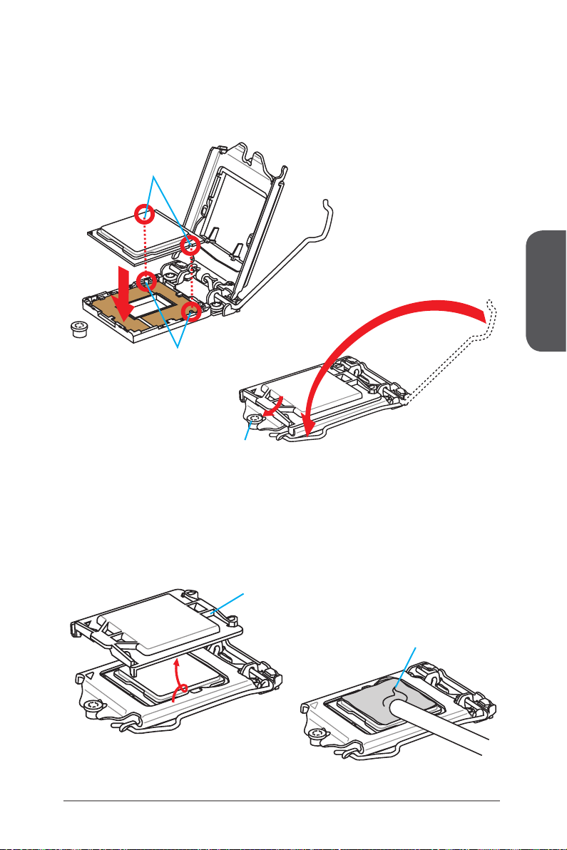
3. Align the notches with the socket alignment keys. Lower the CPU straight down,
without tilting or sliding the CPU in the socket. Inspect the CPU to check if it is
properly seated in the socket.
4. Close and slide the load plate under the retention knob. Close and engage the
load lever.
CPU notches
Alignment Key
Retention knob
English
5. When you press down the load lever the PnP cap will automatically pop up from
the CPU socket. Do not discard the PnP cap. Always replace the PnP cap if the
CPU is removed from the socket.
6. Evenly spread a thin layer of thermal paste (or thermal tape) on the top of the
CPU. This will help in heat dissipation and prevent CPU overheating.
PnP cap
Thermal paste
En-11
Page 24

English
7. Locate the CPU fan connector on the motherboard.
8. Place the heatsink on the motherboard with the fan’s cable facing towards the fan
connector and the fasteners matching the holes on the motherboard.
CPU fan connector
9. Push down the heatsink until the four fasteners get wedged into the holes on
the motherboard. Press the four fasteners down to fasten the heatsink. As each
fastener locks into position a click should be heard.
10. Inspect the motherboard to ensure that the fastener-ends have been properly
locked in place.
11. Finally, attach the CPU fan cable to the CPU fan connector on the motherboard.
Motherboard
Fastener-end
Important
Conrm that the CPU heatsink has formed a tight seal with the CPU before booting
•
your system.
Whenever the CPU is not installed, always protect the CPU socket pins by covering
•
the socket with the plastic cap.
If you purchased a separate CPU and heatsink/ cooler, Please refer to the
•
documentation in the heatsink/ cooler package for more details about installation.
En-12
Page 25
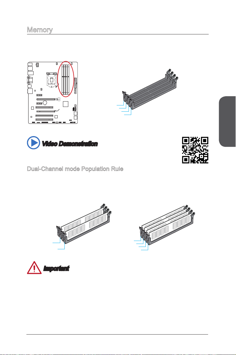
Memory
These DIMM slots are used for installing memory modules. For more information on
compatible components, please visit http://www.msi.com/service/test-report/
DIMM1
DIMM2
DIMM3
DIMM4
Video Demonstration
Watch the video to learn how to install memories at the address below.
http://youtu.be/76yLtJaKlCQ
Dual-Channel mode Population Rule
In Dual-Channel mode, the memory modules can transmit and receive data with two
data bus channels simultaneously. Enabling Dual-Channel mode can enhance system
performance. The following illustrations explain the population rules for Dual-Channel
mode.
English
DIMM2
DIMM4
DIMM1
DIMM2
DIMM3
DIMM4
Important
DDR3 memory modules are not interchangeable with DDR2, and the DDR3
•
standard is not backward compatible. Always install DDR3 memory modules in
DDR3 DIMM slots.
To ensure system stability, memory modules must be of the same type and density
•
in Dual-Channel mode.
Due to chipset resource usage, the system will only detect up to 31+ GB of memory
•
(not full 32 GB) when all DIMM slots have 8GB memory modules installed.
En-13
Page 26
English
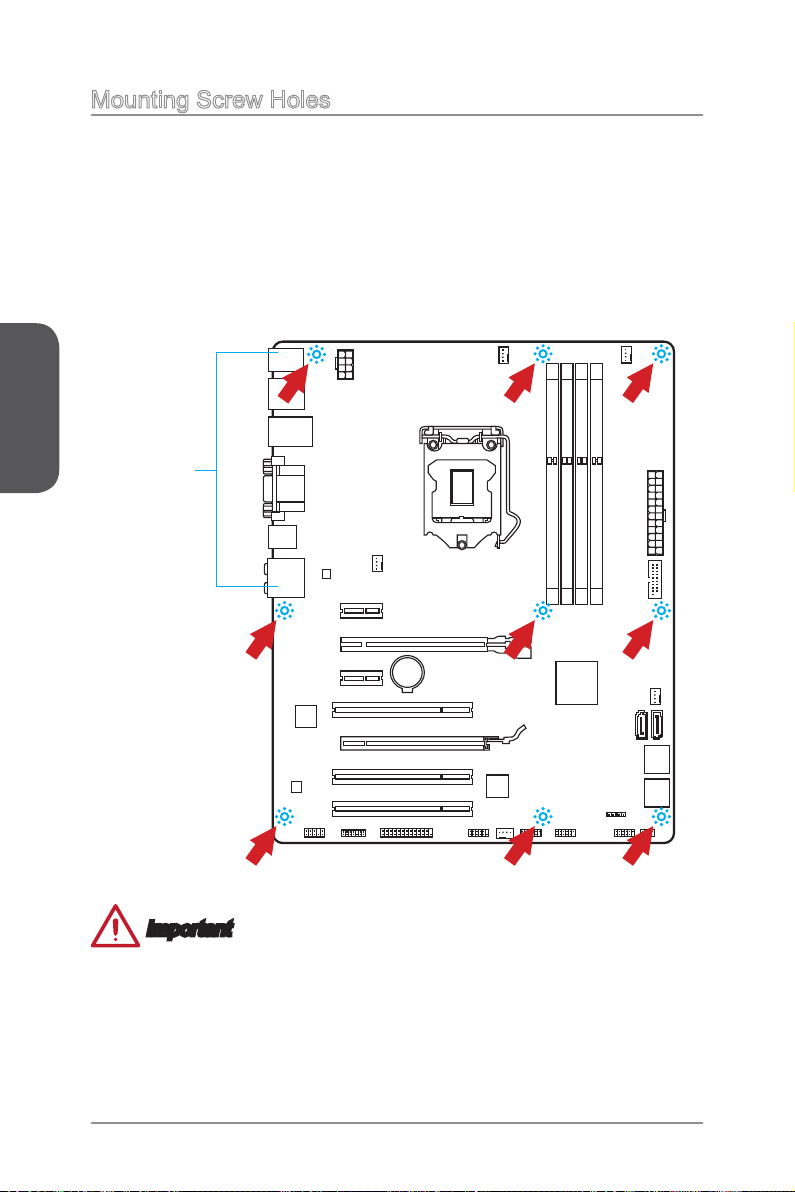
Mounting Screw Holes
When installing the motherboard, rst install the necessary mounting stands required
for an motherboard on the mounting plate in your computer case. If there is an
I/O back plate that came with the computer case, please replace it with the I/O
backplate that came with the motherboard package. The I/O backplate should snap
easily into the computer case without the need for any screws. Align the mounting
plate’s mounting stands with the screw holes on the motherboard and secure the
motherboard with the screws provided with your computer case. The locations of the
screw holes on the motherboard are shown below. For more information, please refer
to the manual that came with the computer case.
The I/O ports should be facing
toward the rear of the computer
case. They should line up with the
holes on the I/O backplate.
Important
Install the motherboard on a at surface free from unnecessary debris.
•
To prevent damage to the motherboard, any contact between the motherboard
•
circuitry and the computer case, except for the mounting stands, is prohibited.
Please make sure there are no loose metal components on the motherboard or
•
within the computer case that may cause a short circuit of the motherboard.
En-14
Page 27
Power Supply
13 .+3 .3
V
1. +3. 3
V
14 .-1 2V
2. +3. 3
V
15 .Gr ou nd
3
.G rou nd
16 .PS -O N
#
4. +5
V
17 .Gr ou nd
5
.G rou nd
18 .Gr ou nd
6. +5
V
19 .Gr ou nd
7
.G rou nd
22 .+5
V
10 .+1 2V
20 .Re s
8. PW
R O
K
23 .+5
V
11
.+ 12V
21 .+5
V
9. 5VS B
24 .Gr ou nd
12 .+3 .3
V
7. +12 V
3.
Gr oun d
5. +12 V
1.
Gr oun d
8. +12 V
4
.G rou nd
6. +12 V
2
.G rou nd
Video Demonstration
Watch the video to learn how to install power supply connectors.
http://youtu.be/gkDYyR_83I4
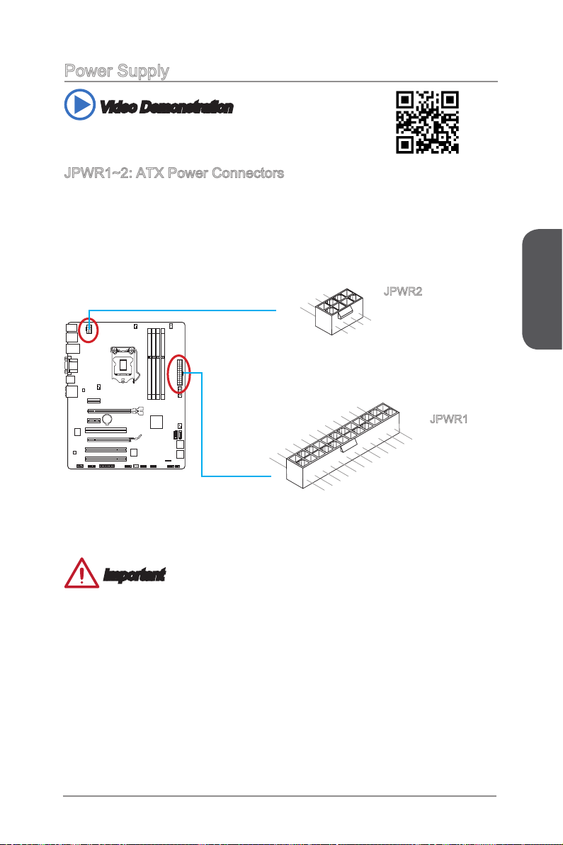
JPWR1~2: ATX Power Connectors
These connectors allow you to connect an ATX power supply. To connect the ATX
power supply, align the power supply cable with the connector and rmly press the
cable into the connector. If done correctly, the clip on the power cable should be
hooked on the motherboard’s power connector.
JPWR2
JPWR1
English
Important
Make sure that all the power cables are securely connected to a proper ATX power
supply to ensure stable operation of the motherboard.
En-15
Page 28
English
Expansion Slots
This motherboard contains numerous slots for expansion cards, such as discrete
graphics or audio cards.
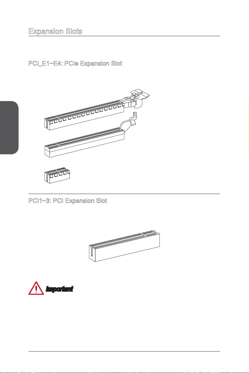
PCI_E1~E4: PCIe Expansion Slot
The PCIe slot supports the PCIe interface expansion card.
PCIe 3.0 x16 Slot
PCIe 2.0 x16 Slot
PCIe 2.0 x1 Slot
PCI1~3: PCI Expansion Slot
The PCI slot supports additional LAN, SCSI, USB, and other add-on cards that comply
with PCI specications.
Important
When adding or removing expansion cards, always turn o the power supply and
unplug the power supply power cable from the power outlet. Read the expansion
card’s documentation to check for any necessary additional hardware or software
changes.
En-16
Page 29
Video/ Graphics Cards
If available, this motherboard takes advantage of the CPU’s integrate graphics
processor, but discrete video cards can be installed by way of the motherboard’s
expansion slots. Adding on one or more discrete video cards will signicantly boost
the system’s graphics performance. For best compatibility, MSI graphics cards are
recommended.
Video Demonstration
Watch the video to learn how to install a graphics card on PCIe x16 slot
with buttery lock.
http://youtu.be/mG0GZpr9w_A
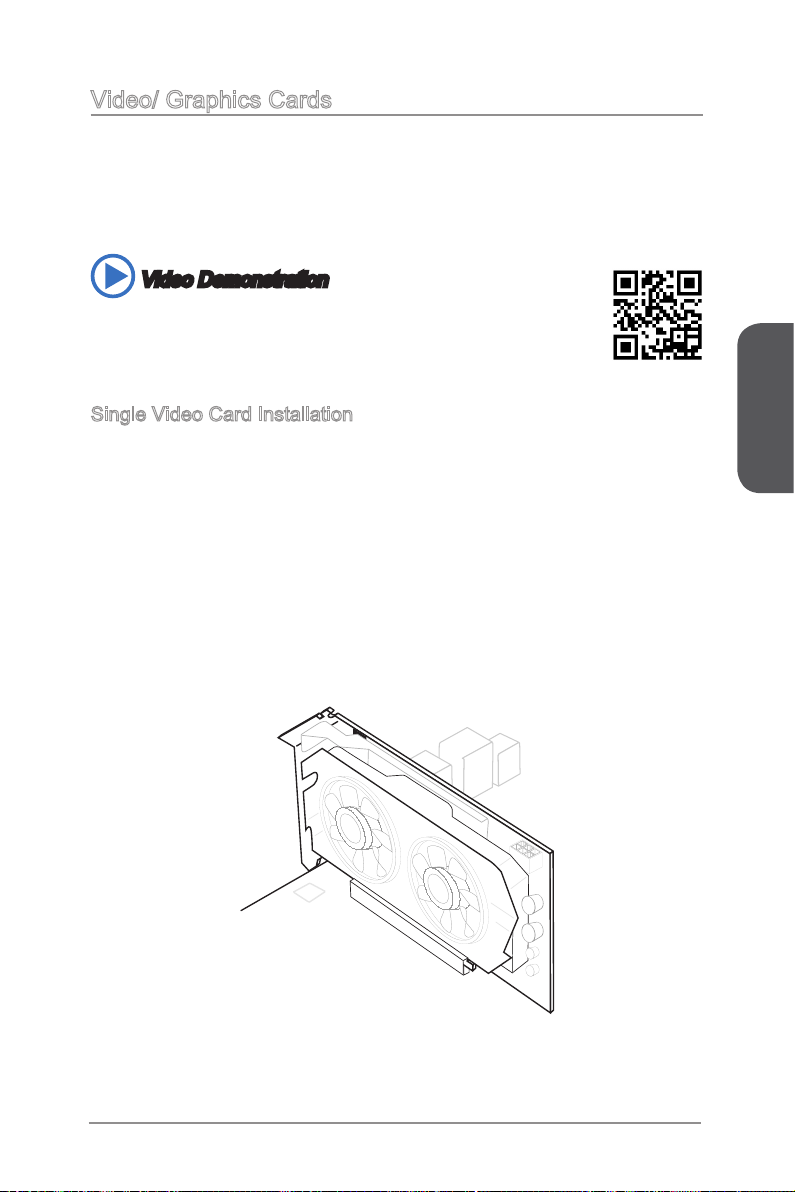
Single Video Card Installation
Determine what type of expansion slot(s) the video card will use. Locate the
1.
expansion slot(s) on the motherboard. Remove any protective expansion slot
covers from the computer case.
Line up the video card on top of the expansion slot(s) with the display ports facing
2.
out of the computer case. For a single video card installation, using the PCI_E2
slot is recommended.
Push the video card into its expansion slot(s). Depending on the expansion slot(s)
3.
used, there should be clip(s) on the expansion slot(s) that will lock in place.
If needed, screw the edge of the graphics card to the computer case. Some video
4.
cards might require a power cable directly from the power supply.
Please consult your video card’s manual for further instructions regarding driver
5.
installation or other special settings.
English
En-17
Page 30
English
Internal Connectors
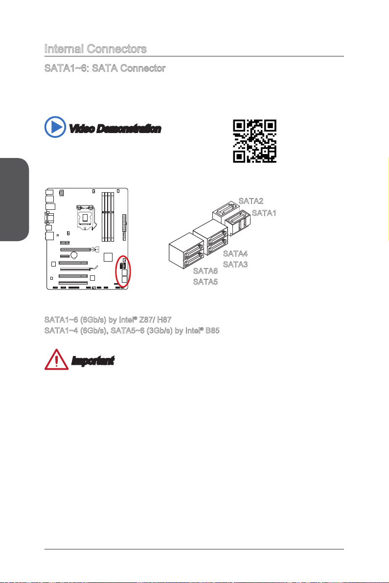
SATA1~6: SATA Connector
This connector is a high-speed SATA interface port. Each connector can connect to
one SATA device. SATA devices include disk drives (HDD), solid state drives (SSD),
and optical drives (CD/ DVD/ Blu-Ray).
Video Demonstration
Watch the video to learn how to Install SATA HDD.
http://youtu.be/RZsMpqxythc
SATA2
SATA1
SATA4
SATA6
SATA5
SATA1~6 (6Gb/s) by Intel® Z87/ H87
SATA1~4 (6Gb/s), SATA5~6 (3Gb/s) by Intel® B85
SATA3
Important
Many SATA devices also need a power cable from the power supply. Such devices
•
include disk drives (HDD), solid state drives (SSD), and optical drives (CD / DVD /
Blu-Ray). Please refer to the device’s manual for further information.
Many computer cases also require that large SATA devices, such as HDDs, SSDs,
•
and optical drives, be screwed down into the case. Refer to the manual that came
with your computer case or your SATA device for further installation instructions.
Please do not fold the SATA cable at a 90-degree angle. Data loss may result
•
during transmission otherwise.
SATA cables have identical plugs on either sides of the cable. However, it is
•
recommended that the at connector be connected to the motherboard for space
saving purposes.
En-18
Page 31

CPUFAN1~2,SYSFAN1~3: Fan Power Connectors
1.Groun d
2.Speed
C
ontro
l
3.Sens
e
4.NC
1
.Ground
2.+12V
3.Sens
e
4.Speed C
ontro
l
The fan power connectors support system cooling fans with +12V. If the motherboard
has a System Hardware Monitor chipset on-board, you must use a specially designed
fan with a speed sensor to take advantage of the CPU fan control. Remember to
connect all system fans. Some system fans may not connect to the motherboard and
will instead connect to the power supply directly. A system fan can be plugged into
any available system fan connector.
CPUFAN1/
CPUFAN2
SYSFAN1/
SYSFAN3/
SYSFAN2
English
Important
Please refer to your processor’s ocial website or consult your vendor to nd
•
recommended CPU heatsink.
These connectors support Smart Fan Control with liner mode. The Command
•
Center utility can be installed to automatically control the fan speeds according to
the CPU’s and system’s temperature.
If there are not enough ports on the motherboard to connect all system fans,
•
adapters are available to connect a fan directly to a power supply.
Before rst boot up, ensure that there are no cables impeding any fan blades.
•
En-19
Page 32

English
1. +
3.
-
10 .N o
Pi
n
5.
Re se t
S
wi tc h
HD D
LE
D
P
ow er
S
wi tc h
P
ow er
LE
D
7.
+
9. Re se rv e
d
8.
-
6.
+
4.
-
2.
+
1
.Ground
3.Suspend
LE
D
5.Power
LE
D
7.No Pi
n
8.
+
6.
-
4.
+
2.
-
Buzz er
S
peak er
JFP1, JFP2: System Panel Connectors
These connectors connect to the front panel switches and LEDs. The JFP1 connector
is compliant with the Intel® Front Panel I/O Connectivity Design Guide. When
installing the front panel connectors, please use the optional M-Connector to simplify
installation. Plug all the wires from the computer case into the M-Connector and then
plug the M-Connector into the motherboard.
Video Demonstration
Watch the video to learn how to Install front panel connectors.
http://youtu.be/DPELIdVNZUI
JFP2
JFP1
Important
On the connectors coming from the case, pins marked by small triangles are
•
positive wires. Please use the diagrams above and the writing on the optional MConnectors to determine correct connector orientation and placement.
The majority of the computer case’s front panel connectors will primarily be plugged
•
into JFP1.
En-20
Page 33

JUSB1~2: USB 2.0 Expansion Connector
1
.
V
C
C
3
.
U
S
B
0
-
1
0
.
NC
5
.
U
S
B
0
+
7
.
G
r
o
u
n
d
9
.
N
o
P
i
n
8
.
G
r
o
u
n
d
6
.
U
S
B
1
+
4
.
U
S
B
1
-
2
.
V
C
C
5.
USB 3_ TX_ C_ DN
4
.Gr ou nd
3.U SB 3_R X_ DP
2.U SB 3_R X_ DN
1.P ow er
10. Gr oun d
9.
+
USB 2. 0
8.
-
U
SB2 .0
7
.Gr ou nd
6.U SB 3_T X_ C_D P
20. No
Pi
n
19. Po wer
18. US B3_ RX _DN
17. US B3_ RX _DP
16. Gr oun d
15. US B3_ TX _C_ DN
14. US B3_ TX _C_ DP
13. Gr oun d
12. US B2. 0
-
11
. +
U
SB2 .0
This connector is designed for connecting high-speed USB peripherals such as USB
HDDs, digital cameras, MP3 players, printers, modems, and many others.
Important
Note that the VCC and GND pins must be connected correctly to avoid possible
damage.
JUSB3: USB 3.0 Expansion Connector
The USB 3.0 port is backwards compatible with USB 2.0 devices. It supports data
transfer rates up to 5Gbits/s (SuperSpeed).
English
Important
Note that the VCC and GND pins must be connected correctly to avoid possible
•
damage.
To use a USB 3.0 device, you must connect the device to a USB 3.0 port through
•
an optional USB 3.0 compliant cable.
En-21
Page 34

English
1
0
.
N
o
P
i
n
1
4
.
G
r
o
u
n
d
8
.
5
V
P
o
w
e
r
1
2
.
G
r
o
u
n
d
6
.
S
e
r
i
a
l
I
R
Q
4
.
3
.
3
V
P
o
w
e
r
2
.
3
V
S
t
a
n
d
b
y
p
o
w
e
r
1
.
L
P
C
C
l
o
c
k
3
.
L
P
C
R
e
s
e
t
5
.
L
P
C
a
d
d
r
e
s
s
&
d
a
t
a
p
i
n
0
7
.
L
P
C
a
d
d
r
e
s
s
&
d
a
t
a
p
i
n
1
9
.
L
P
C
a
d
d
r
e
s
s
&
d
a
t
a
p
i
n
2
1
1
.
L
P
C
a
d
d
r
e
s
s
&
d
a
t
a
p
i
n
3
1
3
.
L
P
C
F
r
a
m
e
2
.
C
I
N
T
R
U
1
.
G
r
o
u
n
d
JTPM1: TPM Module Connector
This connector connects to a optional TPM (Trusted Platform Module) Module. Please
refer to the TPM security platform manual for more details and usages.
JCI1: Chassis Intrusion Connector
This connector connects to the chassis intrusion switch cable. If the computer case is
opened, the chassis intrusion mechanism will be activated. The system will record this
intrusion and a warning message will ash on screen. To clear the warning, you must
enter the BIOS utility and clear the record.
En-22
Page 35

JAUD1: Front Panel Audio Connector
1.MI
C L
3.MI
C R
10.Head
P
hone
Detection
5.Head
P
hone
R
7.SENSE_SEN
D
9.Head
P
hone
L
8.No
Pi
n
6.MI
C D
etection
4.NC
2
.Ground
1
0
.
G
r
o
u
n
d
1
4
.
G
r
o
u
n
d
8
.
L
P
T
_
S
L
I
N
#
1
2
.
G
r
o
u
n
d
6
.
P
I
N
I
T
#
4
.
E
R
R
#
2
.
A
F
D
#
2
4
.
G
r
o
u
n
d
2
2
.
G
r
o
u
n
d
2
6
.
N
o
P
i
n
2
0
.
G
r
o
u
n
d
1
8
.
G
r
o
u
n
d
1
6
.
G
r
o
u
n
d
1
.
R
S
T
B
#
3
.
P
R
N
D
0
5
.
P
R
N
D
1
7
.
P
R
N
D
2
9
.
P
R
N
D
3
1
1
.
P
R
N
D
4
1
3
.
P
R
N
D
5
1
5
.
P
R
N
D
6
1
7
.
P
R
N
D
7
1
9
.
A
C
K
#
2
1
.
B
U
S
Y
2
3
.
P
E
2
5
.
S
L
C
T
This connector allows you to connect the front audio panel located on your computer
case. This connector is compliant with the Intel® Front Panel I/O Connectivity Design
Guide.
JLPT1: Parallel Port Connector
This connector is used to connect an optional parallel port bracket. The parallel port
is a standard printer port that supports Enhanced Parallel Port (EPP) and Extended
Capabilities Parallel Port (ECP) mode.
English
En-23
Page 36

English
1
.
D
C
D
3
.
S
O
U
T
1
0
.
N
o
P
i
n
5
.
G
r
o
u
n
d
7
.
R
T
S
9
.
R
I
8
.
C
T
S
6
.
D
S
R
4
.
D
T
R
2
.
S
I
N
JCOM1: Serial Port Connector
This connector is a 16550A high speed communication port that sends/receives 16
bytes FIFOs. You can attach a serial device.
En-24
Page 37

Jumper
JBAT1: Clear CMOS Jumper
There is CMOS RAM onboard that is external powered from a battery located on the
motherboard to save system conguration data. With the CMOS RAM, the system can
automatically boot into the operating system (OS) every time it is turned on. If you
want to clear the system conguration, set the jumpers to clear the CMOS RAM.
1 1
Keep Data Clear Data
Important
You can clear the CMOS RAM by shorting this jumper while the system is o.
Afterwards, open the jumper . Do not clear the CMOS RAM while the system is on
because it will damage the motherboard.
English
En-25
Page 38

English
Drivers and Utilities
After you install the operating system you will need to install drivers to maximize the
performance of the new computer you just built. MSI motherboard comes with a Driver
Disc. Drivers allow the computer to utilize your motherboard more eciently and take
advantage of any special features we provide.
You can protect your computer from viruses by installing the bundled security
program. The bundle also includes a variety of powerful and creative utilities.
Total Installer
Total Installer is very easy to use and does a great job of nding necessary drivers.
Please follow the steps below to install drivers and utilities for your new computer.
Insert MSI Driver Disc into the optical drive. The setup screen will automatically
1.
appear if autorun is enabled in OS.
Click Total Installer. A popup dialogue will appear listing all necessary drivers.
2.
Click here
Select all checkbox on driver listing dialog.
3.
Click Install button.
4.
The software installation will then be in progress, after it has nished it will prompt
5.
you to restart.
Click OK button to nish.
6.
Restart your computer.
7.
You can also use the same method to install the utilities.
En-26
Page 39

BIOS Setup
CLICK BIOS is developed by MSI that provides a graphical user interface for setting
parameters of BIOS by using the mouse and the keybord.
With the CLICK BIOS, users can change BIOS settings, monitor CPU temperature,
select the boot device priority and view system information such as the CPU name,
DRAM capacity, the OS version and the BIOS version. Users can import and export
parameters data for backup or sharing with friends.
Entering BIOS Setup
Power on the computer and the system will start the Power On Self Test (POST)
process. When the message below appears on the screen, please <DEL> key to enter
BIOS:
Press DEL key to enter Setup Menu, F11 to enter Boot Menu
If the message disappears before you respond and you still need to enter BIOS, restart
the system by turning the computer OFF then back ON or pressing the RESET button.
You may also restart the system by simultaneously pressing <Ctrl>, <Alt>, and <Delete>
keys.
MSI additionally provides two methods to enter the BIOS setup. You can click the
“GO2BIOS” tab on “MSI Fast Boot” utility screen or press the physical “GO2BIOS"
button (optional) on the motherboard to enable the system going to BIOS setup directly
at next boot.
English
Click "GO2BIOS" tab on
"MSI Fast Boot" utility
screen.
Important
Please be sure to install the “MSI Fast Boot” utility before using it to enter the BIOS
•
setup.
The items under each BIOS category described in this chapter are under continuous
•
update for better system performance. Therefore, the description may be slightly
dierent from the latest BIOS and should be held for reference only.
En-27
Page 40

Overview
After entering BIOS, the following screen is displayed.
Genie Button
English
Temperature monitor
Model
name
Virtual OC
BIOS menu
selection
Menu display
Temperature monitor
▶
Shows the temperatures of the processor and the motherboard.
Language
▶
Allows you to select the language of the BIOS setup.
System information
▶
Shows the time, date, CPU name, CPU frequency, DRAM frequency, DRAM capacity
and the BIOS version.
BIOS menu selection
▶
The following options are available:
SETTINGS - Uses this menu to specify the parameters for chipset and boot
■
devices.
OC - This menu contains the frequency and voltage adjustments. Increasing
■
the frequency can get better performance, however high frequency and heat
can cause instability, we do not recommend general users to overclock.
M-FLASH - This menu provides the way to update BIOS with a USB ash
■
disk.
OC PROFILE -This menu is used to set various overclocking proles.
■
HARDWARE MONITOR - This menu is used to set the speeds of fans and
■
monitor voltages of system.
BOARD EXPLORER - It will provide the information of the installed devices on
■
the motherboard.
Language
System
information
Boot device
priority bar
BIOS menu
selection
En-28
Page 41

Boot device priority bar
▶
You can move the device icons to change the boot priority.
High priority Low priority
Menu display
▶
This area provides BIOS settings and information to be congured.
Virtual OC Genie Button
▶
Enables or disables the OC Genie function by clicking on this button. When enabled,
this button will be light. Enabling OC Genie function can automatically overclock with
MSI optimized overclocking prole.
Important
We recommend that you do not to make any modication in OC menu and do not to
•
load defaults after enabling the OC Genie function.
Updating BIOS or clearing CMOS is not allowed in OC Genie mode, and it may
•
cause OC Genie function fail or other eect.
Model Name
▶
Shows the model name of motherboard.
General Help
English
Sub-Menu Scroll bar
Sub-menu
▶
If you nd a point symbol to the left of certain items, that means a sub-menu can be
launched for additional options. You can use the arrow keys or mouse to highlight the
item and press <Enter> or double-click the left mouse button to enter the sub-menu.
Scroll bar
▶
Slide the scroll bar or use the arrow keys to display the other items that are available on
the "menu display" area.
General Help
▶
The General Help displays a brief description to assist you in grasping the selected
item.
En-29
Page 42

Operation
You can control BIOS settings with the mouse and the keyboard. The following table
lists and describes the hot keys and the mouse operations.
Hot key Mouse Description
<↑↓→← >
Select Item
English
Move the cursor
<Enter>
Click/ Double-click
the left button
<Esc>
Click the right button
<+> Increase the numeric value or make changes
<-> Decrease the numeric value or make changes
<F1> General Help
<F4> CPU Specications
<F5> Enter Memory-Z
<F6> Load optimized defaults
<F8> OC Prole Load From USB
<F9> OC Prole Save to USB
<F10> Save Change and Reset
<F12> Save a screenshot to a FAT/FAT32 USB drive
.
Select Icon/ Field
Jump to the Exit menu or return to the previous
from a submenu
En-30
Page 43

OC Menu
This menu is for advanced users who want to overclock the mainboard.
Important
•
Overclocking your PC manually is only recommended for advanced users.
•
Overclocking is not guaranteed, and if done improperly, can void your warranty or
severely damage your hardware.
•
If you are unfamiliar with overclocking, we advise you to use OC Genie for easy
overclocking.
English
Current CPU/ DRAM/ Ring Frequency
▶
These items show the current frequencies of installed CPU and Memory. Read-only.
CPU Base Clock (MHz) [Default]
▶
Sets the CPU Base clock. You may overclock the CPU by adjusting this value. Please
note that overclocking behavior and stability is not guaranteed. This item appears when
the installed processor supports this function.
Current CPU Base Clock Strap (Z87-G43)
▶
Shows the current CPU Base clock strap. Read only. This item can only be changed if
the processor supports this function.
Adjust CPU Base Clock Strap [Auto] (Z87-G43)
▶
Sets the CPU Base Clock Strap. You may overclock the CPU Base Clock by adjusting
this value. Please note that overclocking behavior and stability is not guaranteed. This
item can only be changed if the processor supports this function. If set to "Auto", BIOS
will congure this setting automatically. [Options: Auto, 1.00, 1.25, 1.67]
En-31
Page 44
English
CPU Base Clock Apply Mode [Auto]
▶
Sets the applying mode for adjusted CPU base clock.
[Auto] This setting will be congured automatically by BIOS.
[Next Boot] CPU will run the adjusted CPU base clock after reboot.
[Immediate] CPU runs the adjusted CPU base clock immediately.
CPU PCIE PLL [Auto] (Z87-G43)
▶
Selects a PLL (Phase Lock Loop) mode for CPU PCIe. This item appears when the
installed CPU supports this setting.
[Auto] This setting will be congured automatically by BIOS.
[LC PLL] Enables LC PLL for normal usage.
[SB PLL] Enables SB PLL for extreme overclocking.
Filter PLL [Auto] (Z87-G43)
▶
Enables or disables the lter PLL for CPU. This item appears when the installed CPU
supports this setting.
[Auto] This setting will be congured automatically by BIOS.
[Enabled] Provides wide range of base clock for overclocking when base clock
[Disabled] Provides normal range of base clock.
CPU Ratio Mode [Auto]
▶
Selects the CPU Ratio operating mode.
[Auto] This setting will be congured automatically by BIOS.
[Fixed Mode] Fixes the CPU ratio.
[Dynamic Mode] CPU ratio will be changed dynamically according to the CPU
Adjust CPU Ratio [Auto]
▶
Sets the CPU ratio that is used to determine CPU clock speed. This item can only be
changed if the processor supports this function.
Adjusted CPU Frequency
▶
Shows the adjusted CPU frequency. Read-only.
EIST [Enabled]
▶
Enables or disables the Enhanced Intel® SpeedStep Technology.
[Enabled] Enables the EIST to adjust CPU voltage and core frequency dynamically.
[Disabled] Disables EIST.
Intel Turbo Boost [Enabled]
▶
Enables or disables the Intel® Turbo Boost. This item appears when the installed CPU
supports this function.
[Enabled] Enables this function to boost CPU performance automatically above
[Disabled] Disables this function.
strap be set to higher value.
loading.
It can decrease average power consumption and average heat
production.
rated specications when system request the highest performance
state.
En-32
Page 45

Enhanced Turbo [Auto]
▶
Enables or disables Enhanced Turbo function for all CPU cores to boost CPU
performance.
[Auto] This setting will be congured automatically by BIOS.
[Enabled] All CPU cores would be increased to maximum turbo ratio.
[Disabled] Disables this function.
Adjust Ring Ratio [Auto]
▶
Sets the ring ratio. The valid value range depends on the installed CPU.
Adjusted Ring Frequency
▶
Shows the adjusted Ring frequency. Read-only.
Adjust GT Ratio [Auto]
▶
Sets the integrated graphics ratio. The valid value range depends on the installed
CPU.
Adjusted GT Frequency
▶
Shows the adjusted integrated graphics frequency. Read-only.
DRAM Reference Clock [Auto]
▶
Sets the DRAM reference clock. The valid value range depends on the installed CPU.
This item appears when a CPU that supports this adjustment is installed.
DRAM Frequency [Auto]
▶
Sets the DRAM frequency. Please note the overclocking behavior is not guaranteed.
Adjusted DRAM Frequency
▶
Shows the adjusted DRAM frequency. Read-only.
Extreme Memory Prole (X.M.P) [Disabled]
▶
X.M.P. (Extreme Memory Prole) is the overclocking technology by memory module.
This item will be available when you install the memory modules that support X.M.P.
technology.
[Disabled] Disables this function.
[Prole 1] Uses prole1 over-clocking settings of installed XMP memory module.
[Prole 2] Uses prole2 over-clocking settings of installed XMP memory module.
DRAM Timing Mode [Auto]
▶
Selects the memory timing mode.
[Auto] DRAM timings will be determined based on SPD (Serial Presence Detect)
[Link] Allows user to congure the DRAM timing manually for all memory
[UnLink] Allows user to congure the DRAM timing manually for respective
Advanced DRAM Conguration
▶
Press <Enter> to enter the sub-menu. This sub-menu will be activated after setting [Link]
or [Unlink] in “DRAM Timing Mode”. User can set the memory timing for each memory
channel. The system may become unstable or unbootable after changing memory
timing. If it occurs, please clear the CMOS data and restore the default settings. (Refer
to the Clear CMOS jumper/ button section to clear the CMOS data, and enter the BIOS
to load the default settings.)
of installed memory modules.
channel.
memory channel.
English
En-33
Page 46

English
DRAM Training Conguration
▶
Press <Enter> to enter the sub-menu. Enables or disables the various training ways of
DRAM. The system may become unstable or unbootable after changing these items in
this sub-menu. If it occurs, please clear the CMOS data and restore the default settings.
(Refer to the Clear CMOS jumper/ button section to clear the CMOS data, and enter the
BIOS to load the default settings.)
Memory Fast Boot [Auto]
▶
Enables or disables the initiation and training for memory every booting.
[Auto] This setting will be congured automatically by BIOS.
[Enabled] Memory will completely imitate the archive of rst initiation and rst
[Disabled] The memory will be initialed and trained every booting.
DigitALL Power
▶
Press <Enter> to enter the sub-menu. Controls the digital powers related to CPU
PWM.
CPU Phase Control [Auto]
▶
Controls PWM phase proportionally to the CPU loading. If set to "Auto", BIOS will
optimize the CPU PWM phase automatically.
[Auto] This setting will be congured automatically by BIOS.
[Disabled] Disables the PWM power phase switching feature.
CPU Vdroop Offset Control [Auto]
▶
Sets a percentage of oset voltage for CPU vdroop. If set to "Auto", BIOS will
congure this setting automatically. [Options: Auto, +12.5%, +25%, +37.5%, +50%,
+62.5%, +75%, +87.5%, +100%]
CPU Over Voltage Protection [Auto]
▶
Sets the voltage limit for CPU over-voltage protection. If set to "Auto", BIOS will
congure this setting automatically. Higher voltage provides less protection and
may damage the system.
CPU Under Voltage Protection [Auto]
▶
Sets the voltage limit for CPU under-voltage protection. If set to "Auto", BIOS will
congure this setting automatically. Higher voltage provides less protection and may
damage the system.
CPU Over Current Protection [Auto]
▶
Sets the current limit for CPU over-current protection. If set to "Auto", BIOS will
congure this setting automatically. Higher percentage provides less protection and
may damage the system.
Phase Over Current Protection [Enabled]
▶
Enables or disables the phase over-current protection.
[Enabled] Sets the current limit on the phase for over-current protection.
[Disabled] Disables this function.
training. After that, the memory will not be initialed and trained when
booting to accelerate the system booting time.
En-34
Page 47

CPU Switching Frequency [Auto]
▶
Sets the PWM working speed to stabilize CPU Core voltage and minimize ripple
range. Increasing the PWM working speed will cause higher temperature of MOSFET.
So please make sure a cooling solution is well-prepared for MOSFET before you
increase the value. If set to "Auto", BIOS will congure this setting automatically.
CPU VRM Over Temperature Protection [Enabled]
▶
Enables or disables the CPU VRM over-temperature protection.
[Enabled] Sets the temperature limit on CPU VRM for over-temperature protec
[Disabled] Disables this function.
Digital Compensation Level [Auto]
▶
Sets the current compensation level for CPU PWM when the MOS phases are
changed. If set to "Auto", BIOS will congure this setting automatically. Higher
compensation level provides more overclocking ability.
Imon Overwrite [Auto]
▶
Sets the Imon current for CPU.
[Auto] This setting will be congured automatically by BIOS.
[Quarter] Sets the Imon current into quarter.
[Half] Sets the Imon current into half.
[Disabled] Sets the default values for Imon current.
Transient Boost [Disabled]
▶
Enables or disables the transient boost.
[Enabled] Enables this function may lead into a stable system under heavy sys
[Disabled] Disables this function.
SVID Communication [Auto]
▶
Enables or disables SVID (Serial Voltage Identication) support.
[Auto] This setting will be congured automatically by BIOS.
[Enabled] PWM phase will be changed dynamically according to the CPU SVID
[Disabled] Disables SVID (Serial Voltage Identication) support.
VCCIN Voltage [Auto]
▶
Sets the CPU input voltage. The CPU input voltage is the CPU power source that is
shared with components of the CPU.
Current VCCIN Voltage
▶
Shows current CPU VCCIN voltage. Read-only.
CPU Core Voltage Mode/ CPU Ring Voltage Mode/ CPU GT Voltage Mode [Auto]
▶
Selects the control modes for these voltages.
[Auto] This setting will be congured automatically by BIOS.
[Adaptive Mode] Sets adaptive voltages automatically for optimizing the system
[Override Mode] Allows you to set these voltages manually.
tion.
tem loading.
(Serial Voltage Identication).
performance.
-
English
-
En-35
Page 48

English
CPU Core Voltage/ CPU Ring Voltage/ CPU GT Voltage [Auto]
▶
Sets these voltages. If set to "Auto", BIOS will set these voltages automatically or you
can set it manually.
CPU Core Voltage Oset Mode/ CPU Ring Voltage Oset Mode/ CPU GT Voltage
▶
Oset Mode/ CPU SA Voltage Oset Mode/ CPU IO Analog Voltage Oset Mode/ CPU
IO Digital Voltage Oset Mode [Auto]
Selects the voltage oset modes.
[Auto] This setting will be congured automatically by BIOS.
[+] Allows you to set the positive oset voltage.
[-] Allows you to set the negative oset voltage.
CPU Core Voltage Oset/ CPU Ring Voltage Oset/ CPU GT Voltage Oset/ CPU SA
▶
Voltage Oset/ CPU IO Analog Voltage Oset/ CPU IO Digital Voltage Oset [Auto]
Set the oset values for these voltages.
Current CPU Core Voltage/ Current CPU Ring Voltage/ Current CPU GT Voltage/
▶
Current CPU SA Voltage/ Current CPU IO Digital Voltage
Show the current voltages. Read-only.
Internal VR OVP OCP Protection [Auto]
▶
Enables or disables the over-voltage protection and over-current protection for CPU
internal VR (Voltage Regulator).
[Auto] This setting will be congured automatically by BIOS.
[Enabled] Sets the voltage limit on the CPU internal VR for over-voltage protection
[Disabled] Disables this function for overclocking.
Internal VR Eciency Management [Auto]
▶
Enables or disables the CPU internal VR eciency management.
[Auto] This setting will be congured automatically by BIOS.
[Enabled] Enables the VR eciency management for power-saving control.
[Disabled] Disables this function.
DRAM Voltage [Auto]
▶
Sets the memory voltage. If set to "Auto", BIOS will set memory voltage automatically
or you can set it manually.
Current DRAM Voltage
▶
Shows current memory voltage. Read only.
DDR_VREF_CA/ DDR_VREF_DQ_A/ DDR_VREF_DQ_B/ PCH 1.05 Voltage/ PCH
▶
1.5 Voltage
Set these voltages. If set to "Auto", BIOS will set these voltages automatically or you
can set it manually.
Current PCH 1.05 Voltage
▶
Shows current PCH 1.05 voltage. Read only.
and over-current protection.
En-36
Page 49

CPU Memory Changed Detect [Enabled]
▶
Enables or disables the system to issue a warning message during boot when the CPU
or memory has been replaced.
[Enabled] The system will issue a warning message during boot and than needs to
[Disabled] Disables this function and keeps the current BIOS settings.
Spread Spectrum
▶
This function reduces the EMI (Electromagnetic Interference) generated by modulating
clock generator pulses.
[Enabled] Enables the spread spectrum function to reduce the EMI (Electromagnetic
[Disabled] Enhances the overclocking ability of CPU Base clock.
load the default settings for new devices.
Interference) problem.
Important
If you do not have any EMI problem, leave the setting at [Disabled] for optimal
•
system stability and performance. But if you are plagued by EMI, select the value of
Spread Spectrum for EMI reduction.
The greater the Spread Spectrum value is, the greater the EMI is reduced, and
•
the system will become less stable. For the most suitable Spread Spectrum value,
please consult your local EMI regulation.
Remember to disable Spread Spectrum if you are overclocking because even a
•
slight jitter can introduce a temporary boost in clock speed which may just cause
your overclocked processor to lock up.
CPU Specications
▶
Press <Enter> to enter the sub-menu. This sub-menu displays the information of
installed CPU. You can also access this information menu at any time by pressing [F4].
Read only.
CPU Technology Support
▶
Press <Enter> to enter the sub-menu. The sub-menu shows what the key features
does the installed CPU support. Read only.
MEMORY-Z
▶
Press <Enter> to enter the sub-menu. This sub-menu displays all the settings and
timings of installed memory. You can also access this information menu at any time by
pressing [F5].
DIMM1~4 Memory SPD
▶
Press <Enter> to enter the sub-menu. The sub-menu displays the information of
installed memory. Read only.
CPU Features
▶
Press <Enter> to enter the sub-menu.
English
En-37
Page 50

English
Hyper-Threading Technology [Enabled]
▶
The processor uses Hyper-Threading technology to increase transaction rates and
reduces end-user response times. Intel Hyper-Threading technology treats the multi
cores inside the processor as multi logical processors that can execute instructions
simultaneously. In this way, the system performance is highly improved.
[Enable] Enables Intel Hyper-Threading technology.
[Disabled] Disables this item if the system does not support HT function.
Active Processor Cores [All]
▶
This item allows you to select the number of active processor cores.
Limit CPUID Maximum [Disabled]
▶
Enables or disables the extended CPUID value.
[Enabled] BIOS will limit the maximum CPUID input value to circumvent boot
[Disabled] Use the actual maximum CPUID input value.
Execute Disable Bit [Enabled]
▶
Intel’s Execute Disable Bit functionality can prevent certain classes of malicious
“buer overow” attacks where worms attempt to execute code to damage the
system. It is recommended that keeps this item enabled always.
[Enabled] Enables NO-Execution protection to prevent the malicious attacks
[Disabled] Disables this function.
Intel Virtualization Tech [Enabled]
▶
Enables or disables Intel Virtualization technology.
[Enabled] Enables Intel Virtualization technology and allows a platform to run
[Disabled] Disables this function.
Hardware Prefetcher [Enabled]
▶
Enables or disables the hardware prefetcher (MLC Streamer prefetcher).
[Enabled] Allows the hardware prefetcher to automatically pre-fetch data and
[Disabled] Disables the hardware prefetcher.
Adjacent Cache Line Prefetch [Enabled]
▶
Enables or disables the CPU hardware prefetcher (MLC Spatial prefetcher).
[Enabled] Enables adjacent cache line prefetching for reducing the cache la
[Disabled] Enables the requested cache line only.
problems with older operating system that do not support the processor with extended CPUID value.
and worms.
multiple operating systems in independent partitions. The system can
function as multiple systems virtually.
instructions into L2 cache from memory for tuning the CPU performance.
tency time and tuning the performance to the specic application.
-
En-38
Page 51

CPU AES Instructions [Enabled]
▶
Enables or disables the CPU AES (Advanced Encryption Standard-New Instructions)
support. This item appears when a CPU supports this function.
[Enabled] Enables Intel AES support.
[Disabled] Disables Intel AES support.
Intel Adaptive Thermal Monitor [Enabled]
▶
Enables or disables the Intel adaptive thermal monitor function to protect the CPU
from overheating.
[Enabled] Throttles down the CPU core clock speed when the CPU is over the
[Disabled] Disables this function.
Intel C-State [Enabled]
▶
C-state is a processor power management technology dened by ACPI.
[Auto] This setting will be congured automatically by BIOS.
[Enabled] Detects the idle state of system and reduce CPU power consumption
[Disabled] Disable this function.
C1E Support [Disabled]
▶
Enables or disables the C1E function for power-saving in halt state. This item
appears when "Intel C-Statel" is enabled.
[Enabled] Enables C1E function to reduce the CPU frequency and voltage for
[Disabled] Disables this function.
Package C State limit [Auto]
▶
This item allows you to select a CPU C-state mode for power-saving when system is
idle. This item appears when "Intel C-Statel" is enabled.
[Auto] This setting will be congured automatically by BIOS.
[C0~C7s] The power-saving level from high to low is C7s, C7, C6, C3, C2, then
[No limit] No c-state limit for CPU.
LakeTiny Feature [Disabled]
▶
Enables or disables Intel Lake Tiny technology with iRST for SSD. This item appears
when "Intel C-State" is enabled.
[Enabled] Enhance the dynamic IO load adjusted performance for accelerating
[Disabled] Disables this feature.
adaptive temperature.
accordingly.
power-saving in halt state.
C0.
the SSD speed.
English
En-39
Page 52

English
Note: The following items will appear when "Intel Turbo Boost " is enabled.
Long Duration Power Limit (W) [Auto]
▶
Sets the long duration TDP power limit for CPU in Turbo Boost mode.
Long Duration Maintained (s) [Auto]
▶
Sets the maintaining time for "Long duration power Limit(W)".
Short Duration Power Limit (W) [Auto]
▶
Sets the short duration TDP power limit for CPU in Turbo Boost mode.
CPU Current limit (A) [Auto]
▶
Sets maximum current limit of CPU package in Turbo Boost mode. When the current
is over the specied limit value, the CPU will automatically reduce the core frequency
for reducing the current.
1/2/3/4-Core Ratio Limit [Auto]
▶
These items only appear when a CPU that support this function is installed. These
items allow you to set the CPU ratios for dierent number of active cores in turbo boost
mode. These items appear when the installed processor supports this function.
En-40
Page 53

Deutsch
Danke, dass Sie das Z87-G43/ H87-G43/ B85-G43 (MS-7816 v1.X)
ATX Motherboard gewählt haben. Diese Z87-G43/ H87-G43/ B85-G43
Motherboard basiert auf dem Intel® Z87/ H87/ B85 Chipsatz und ermöglicht
so ein optimales und ezientes System. Entworfen, um den hochentwickelten
Intel® LGA1150 Prozessor zu unterstützen, stellt die Z87-G43/ H87G43/ B85-G43 die ideale Lösung zum Aufbau eines professionellen
Hochleistungsdesktopsystems dar.
Page 54

Spezikationen
Deutsch
Prozessor Die Intel® Core™ i7 / Core™ i5 / Core™ i3 / Pentium® / Celeron
■
Prozessoren der 4. Generation für LGA 1150 Sockel
Chipsatz Intel® Z87 Express Chipsatz (Z87-G43)
Speicher 4x DDR3 Speicherplätze unterstützen bis zu 32GB
■
Intel® H87 Express Chipsatz (H87-G43)*
■
Intel® B85 Express Chipsatz (B85-G43)*
■
* Unterstützt Intel® SBA.
■
Unterstützt DDR3 3000(OC)/ 2800(OC)/ 2666(OC)/ 2600(OC)/
■
2400(OC)/ 2200(OC)/ 2133(OC)/ 2000(OC)/ 1866(OC)/ 1600/
1333/ 1066 MHz
OC ist nur für Z87-G43.
-
Dual-Kanal-Speicherarchitektur
■
Unterstützt ungepuerte Non-ECC-Speicher
■
Unterstützt Intel® Extreme Memory Prole (XMP)
■
Erweiterunganschlüsse
OnboardGrak
1x PCIe 3.0 x16-Steckplatz
■
1x PCIe 2.0 x16-Steckplatz
■
Unterstützt bis zu PCIe 2.0 x4 Lanes.
-
2x PCIe 2.0 x1-Steckplätze
■
3x PCI-Steckplätze
■
1x VGA Anschluss, unterstützt eine maximale Auösung
■
1920x1200 @ 60H
1x HDMI Anschluss, unterstützt eine maximale Auösung
■
von 4096x2160@24Hz, 24bpp/ 2560x1600@60Hz, 24bpp/
1920x1080@60Hz, 36bpp
1x DVI-D Anschluss, unterstützt eine maximale Auösung
■
1920x1200 @ 60Hz
Multi-GPU Unterstützung von zwei Grakkarten mittels AMD CrossFire
■
TM
Technologie*
* Betriebssystemunterstützung: Windows 7 und Windows 8.
Aufbewahrung Intel Z87/ H87/ B85 Express Chipsatz
■
6x SATA 6Gb/s Anschlüsse (SATA1~6) (Z87-G43/ H87-G43)
4x SATA 6Gb/s Anschlüsse (SATA1~4) (B85-G43)
2x SATA 3Gb/s Anschlüsse (SATA5~6) (B85-G43)
Unterstützt RAID 0, RAID1, RAID 5 und RAID 10 (Für Z87-
G43/ H87-G43)
Unterstützt die Intel Smart Response Technologie* (Z87-G43
and H87-G43)
Unterstützt die Intel® Rapid Start Technologie und Intel® Smart
Connect Technologie*
* Unterstützt die Intel Core Prozessoren auf Windows 7 and Windows 8.
USB Intel Z87/ H87/ B85 Express Chipsatz
■
4x USB 3.0 Anschlüsse (2 Anschlüsse an der Rückwand, 2
Anschlüsse stehen durch die internen USB Anschlüsse zur
Verfügung)
10x USB 2.0 Anschlüsse (6 Anschlüsse an der Rückwand, 4
Anschlüsse stehen durch die internen USB Anschlüsse zur
Verfügung)
Audio Realtek® ALC892 Codec
■
7,1-Kanal-HD-Audio
-
®
De-2
Page 55

LAN 1x Realtek® 8111E Gigabit LAN Controller■
Hintere Ein-/
und Ausgänge
Interne
Anschlüsse
E/A Anschluss NUVOTON NCT6779 Controller Chip■
Hardware-
Monitor
BIOS
Funktionen
Besonderheiten
PS/2 Tastatur-/Maus-Combo-Anschluss x1
■
USB 2.0 Anschlüsse x6
■
HDMI Anschluss x1
■
VGA Anschluss x1
■
DVI-D Anschluss x1
■
LAN (RJ45) Anschluss x1
■
USB 3.0 Anschlüsse x2
■
Audiobuchsen x6
■
ATX 24-poliger Stromanschluss x1
■
ATX12V 8-poliger Stromanschluss x1
■
SATA 6Gb/s Anschlüsse x6
■
Für Z87-G43/ H87-G43.
-
SATA 6Gb/s Anschlüsse x4 und SATA 3Gb/s Anschlüsse x2
■
Für B85-G43.
-
USB 2.0 Anschlüsse x2 (unterstützt zusätzliche 4 USB 2.0-Ports)
■
USB 3.0 Anschluss x1 (unterstützt zusätzliche 2 USB 3.0-Ports)
■
4-poliger CPU-Lüfter-Anschlüsse x2
■
4-poliger System-Lüfter-Anschlüsse x3
■
Steckbrücke zur CMOS-Löschung x1
■
Audioanschluss des Frontpanels x1
■
Systemtafelanschlüsse x2
■
TPM Anschluss x1
■
Serielle Stiftleiste x1
■
Parallele Stiftleiste x1
■
Gehäusekontaktschalter x1
■
CPU/System Temperaturerfassung
■
CPU/System Geschwindigkeitserfassung
■
CPU/System Lüfterdrehzahlregelung
■
64 Mb Flash (Z87-G43)
■
128 Mb Flash (H87-G43/ B85-G43)
■
UEFI AMI BIOS
■
ACPI 5.0, PnP 1.0a, SM BIOS 2.7, DMI 2.0
■
Mehrsprachenunterstützung
■
DigitALL Power
■
Military Class 4
■
OC Genie 4
■
CLICK BIOS 4
■
All Solid CAPs
■
AMD CrossFire
■
PCI Express Gen 3
■
Sound Blaster Cinema (optional)
■
Super RAID
■
USB 3.0
■
SATA 6Gb/s
■
HDMI
■
Kommandozentrale
■
Live Update
■
M-Flash
■
Deutsch
De-3
Page 56

Software Treiber
Form Faktor ATX Form Faktor
■
MSI
■
Kommandozentrale
Super Charger
Super RAID
Live Update 5
Fast Boot
-
7-ZIP
■
Intel Turbo Boost Monitor
■
Intel Extreme Tuning Utility
■
Intel Small Business Advantage (optional)
■
Sound Blaster Cinema (optional)
■
Norton Internet Security Solution
■
Trend Micro SafeSync
■
■
12 Zoll x 9,6 Zoll (30,5 cm x 24,4 cm)
■
Weitere CPU Informationen nden Sie unter
http://www.msi.com/service/cpu-support/
Deutsch
Die neusten Informationen über kompatible Bauteile nden Sie
unter http://www.msi.com/service/test-report/
De-4
Page 57

Anschlussübersicht
Rücktafel
PCI_E1
PCI_E2
PCI_E3
PCI1
PCI_E4
PCI2
PCI3
SYSFAN1
JPWR2
CPU Sockel
CPUFAN1
DIMM1
DIMM2
DIMM3
DIMM4
CPUFAN2
JPWR1
JUSB3
JBAT1
SATA2
SYSFAN3
SATA1
SATA3_4
SATA5_6
JCI1
JFP2
Deutsch
JAUD1
JTPM1
JLPT1
JFP1
JUSB2
JUSB1
SYSFAN2
JCOM1
De-5
Page 58

Übersicht der Motherboard-Anschlüsse
Deutsch
Port-Name Port-Typ Seite
Rücktafel E/A Anschlüsse De-7
CPU Sockel LGA1150 CPU Sockel
CPUFAN1~2,SYSFAN1~3
DIMM1~4 DDR3
JAUD1
JBAT1
JCI1
JCOM1 Serieller Anschluss De-24
JFP1, JFP2 Systemtafelanschlüsse
JLPT1 Parallele Schnittstelle De-
JPWR1~2
JTPM1 TPM Anschluss De-
JUSB1~2
JUSB3
PCI_E1, 3 PCIe x1
PCI_E2, 4 PCIe x16
PCI1~3 PCI
SATA1~6
Stromanschlüsse für Lüfter De-19
Speichersteckplätze De-13
Audioanschluss des Frontpanels De-23
Steckbrücke zur CMOS-Löschung De-25
Gehäusekontaktanschluss De-22
ATX Stromanschlüsse De-15
USB 2.0 Erweiterungsanschlüsse De-21
USB 3.0 Erweiterungsanschluss De-21
Erweiterungssteckplätze De-16
Erweiterungssteckplätze De-16
Erweiterungssteckplätze De-16
SATA Anschlüsse De-18
De-10
De-20
23
22
De-6
Page 59

Rücktafel-Übersicht
PS/2 Tastatur/
Maus Combo
Anschluss
USB 2.0
Anschluss
PS/2 Tastatur/Maus Combo Anschluss
▶
USB 2.0
Anschluss
HDMI
LAN
Anschluss
USB 2.0
Anschluss
VGA
DVI-D Anschluss
USB 3.0
Anschluss
Line-In
Line-Out
Mic
RS-Out
CS-Out
SS-Out
Die Standard PS/2® Maus/Tastatur Stecker DIN ist für eine PS/2® Maus/Tastatur.
VGA Anschluss
▶
Die DB 15-Pin Buchse dient zum Anschluss eines VGA Monitors.
DVI-D Anschluss
▶
Der DVI-D (Digital Visual Interface- Digital) Anschluss erlaubt Ihnen, einen LCD- oder
CRT-Monitor anzuschließen. Um einen Monitor anzuschließen, können Sie weitere
Informationen dem Handbuch Ihres Monitors entnehmen.
HDMI Anschluss
▶
Das High-Denition Multimedia Interface (kurz HDMI) ist eine Schnittstelle für die
volldigitale Übertragung von dekomprimierten Audio- und Video-Daten. Dieser HDMI
unterstützt alle Formate für Fernsehen, einschließlich Standard- und Enhanced- oder
HD-Video sowie das Audioformate der Unterhaltungselektronik.
Wichtig
Diese Plattform unterstützt die Ausgabe über 2- oder 3 Displays:
VGA+DVI-D DVI-D+HDMI HDMI+VGA HDMI+VGA+DVI-D
Erweiterter-Modus
(Erweiterung des
Desktops den anderen
Monitor)
Clone-Modus
(Monitore zeigen das
gleiche Bild)
◯ ◯ ◯ ◯
◯ ◯ ◯ ◯
Deutsch
USB 2.0 Anschluss
▶
Der USB 2.0 Anschluss dient zum direkten Anschluss von USB 2.0-Geräten, wie etwa
Tastatur, Maus oder weiterer USB 2.0-kompatibler Geräte.
De-7
Page 60

▶
Der USB 3.0 Anschluss ist abwärtskompatibel mit USB 2.0-Geräten. Er unterstützt
Datentransferraten bis zu 5 Gbit/s (SuperSpeed).
Um ein USB 3.0 einzusetzen, schließen Sie es bitte mit einem USB 3.0 kompatiblen
Kabel an einen USB 3.0 Anschluss an.
▶
Die Standard RJ-45 Buchse dient zur Verbindung in einem lokalen Netzwerk (LAN).
▶
Deutsch
Diese Audioanschlüsse dienen zur Verbindung mit Audiogeräten. Durch die Farben
erkennen Sie die unterschiedlichen Funktionen der Audioanschlüsse.
USB 3.0 Anschluss
Wichtig
LAN Port
LED LED Status Bezeichnung
Link/ Activity LED
LINK/ACT
LED
SPEED
LED
(Verbindung/
Aktivität LED)
Speed LED
(Geschwindigkeit
LED)
Audioanschlüsse
Blau - Line-In : Der Anschluss “Line In” kann externe Audioausgabegeräte
■
aufnehmen.
Grün - Line-Out : An den Anschluss “Line Out” können Sie Lautsprecher oder
■
Kopfhörer anschließen.
Rosa - Mikrofon : Der Anschluss “Mic” nimmt ein Mikrofon auf.
■
Schwarz - RS-Out : Dieser Anschluss nimmt die hinteren Surround-
■
Lautsprecher im 4/ 5,1/ 7,1-Kanalmodus auf.
Orange - CS-Out : Dieser Anschluss nimmt die mittleren oder Subwoofer-
■
Lautsprecher im 5,1/ 7,1-Kanalmodus auf.
Grau - SS-Out : Dieser Anschluss nimmt die seitlichen Surround-Lautsprecher
■
im 7,1-Kanalmodus auf.
Aus Keine Verbindung
Gelb Verbindung
Blinkt Datenaktivität
Aus 10 Mbps-Verbindung
Grün 100 Mbps-Verbindung
Orange 1 Gbps-Verbindung
De-8
Page 61

CPU (Prozessor)
Erklärung zur LGA 1150 CPU
Die Obserseite der LGA 1150 CPU hat zwei Justierungen und ein gelbes Dreieck
um die korrekte Ausrichtung der CPU auf dem Motherboard zu gewährleisten.
Das gelbe Dreieck des Prozessors deniert die Position des ersten Pins.
Kerbe
Das goldene Dreieck des Prozessors
deniert die Position des ersten Pins
Kerbe
Wichtig
Überhitzung
Überhitzung beschädigt die CPU und das System nachhaltig. Stellen Sie stets eine
korrekte Funktionsweise des CPU Kühlers sicher, um die CPU vor Überhitzung zu
schützen. Überprüfen Sie eine gleichmäßige Schicht der thermischen Paste (oder
thermischen Klebeandes) zwischen der CPU und dem Kühlblech anwenden, um
Wärmeableitung zu erhöhen.
CPU Wechsel
Stellen Sie vor einem Wechsel des Prozessors stets sicher, dass das Netzteil
ausgeschaltet und der Netzstecker gezogen ist, um die Unversehrtheit der CPU zu
gewährleisten.
Übertakten
Dieses Motherboard wurde so entworfen, dass es Übertakten unterstützt. Stellen
Sie jedoch bitte sicher, dass die betroenen Komponenten mit den abweichenden
Einstellungen während des Übertaktens zurecht kommen. Von jedem Versuch
des Betriebes außerhalb der Produktspezikationen kann nur abgeraten werden.
Wir übernehmen keinerlei Garantie für die Schäden und Risiken, die aus einem
unzulässigem Betrieb oder einem Betrieb außerhalb der Produktspezikation
resultieren.
Deutsch
De-9
Page 62
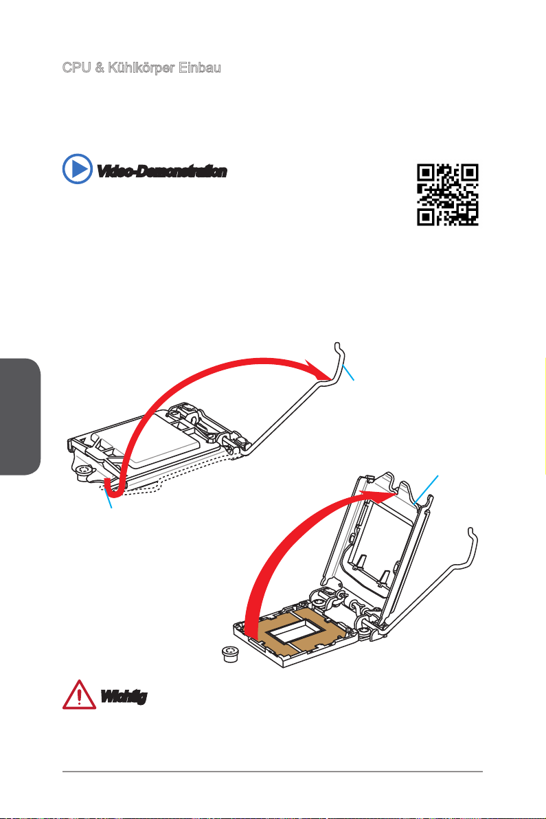
CPU & Kühlkörper Einbau
Wenn Sie die CPU einbauen, denken sie bitte daran einen CPU-Kühler zu installieren.
Ein CPU-Kühlkörper ist notwendig, um eine Überhitzung zu vermeiden und die
Systemstabilität beizubehalten. Befolgen Sie die nachstehenden Schritte, um die
richtige CPU und CPU-Kühlkörper Installation zu gewährleisten. Ein fehlerhafter
Einbau führt zu Schäden an der CPU und dem Motherboard.
Video-Demonstration
Anhand dieses Video an untenstehende Adresse lernen Sie, wie Sie
CPU & Kühlkörper installieren.
http://youtu.be/bf5La099urI
1. Drücken Sie den Verschlusshebel nach unten zum Önen des Hebels und önen
Sie anschließend die Abdeckplatte.
2. Die Abdeckplatte sollte nach vollständigem zurückklappen des Verschlusshebels
mit nach hinten klappen.
Deutsch
Berühren Sie die Sockelkontakte oder die Unterseite der CPU nicht.
Verschlusshebel
Abdeckplatte
Rückhaltehaken
Wichtig
De-10
Page 63

3. Positionieren Sie die Kerben mit die Justiermarkierungen des Sockels. Setzen
Sie die CPU nach unten, ohne Kippen oder Schieben der CPU im Sockel.
Begutachten Sie, ob die CPU richtig im Sockel sitzt.
4. Schließen Sie und schieben Sie die Abdeckplatte unter dem Rückhalteknopf.
Verschließen Sie den Verschlusshebel.
CPU Kerben
Justiermarkierungen
Rückhalteknopf
5. Wenn Sie den Verschlusshebel herunterdrücken, wird die PnP-Abdeckung aus
dem CPU-Sockel automatisch getrennt. Bitte bewahren Sie die PnP-Abdeckung.
Setzen Sie bitte immer die PnP-Abdeckung ein, wenn die CPU aus dem Sockel
entfernt wird.
6. Verteilen Sie die dann eine geeignete Wärmeleitpaste oder ein Wärmeleitpad
auf der Oberseite der eingesetzten CPU. Dies verbessert die Wärmeableitung
maßgeblich und verhindert damit die Überhitzung des Prozessors.
PnP-Abdeckung
Wärmeleitpaste
De-11
Deutsch
Page 64
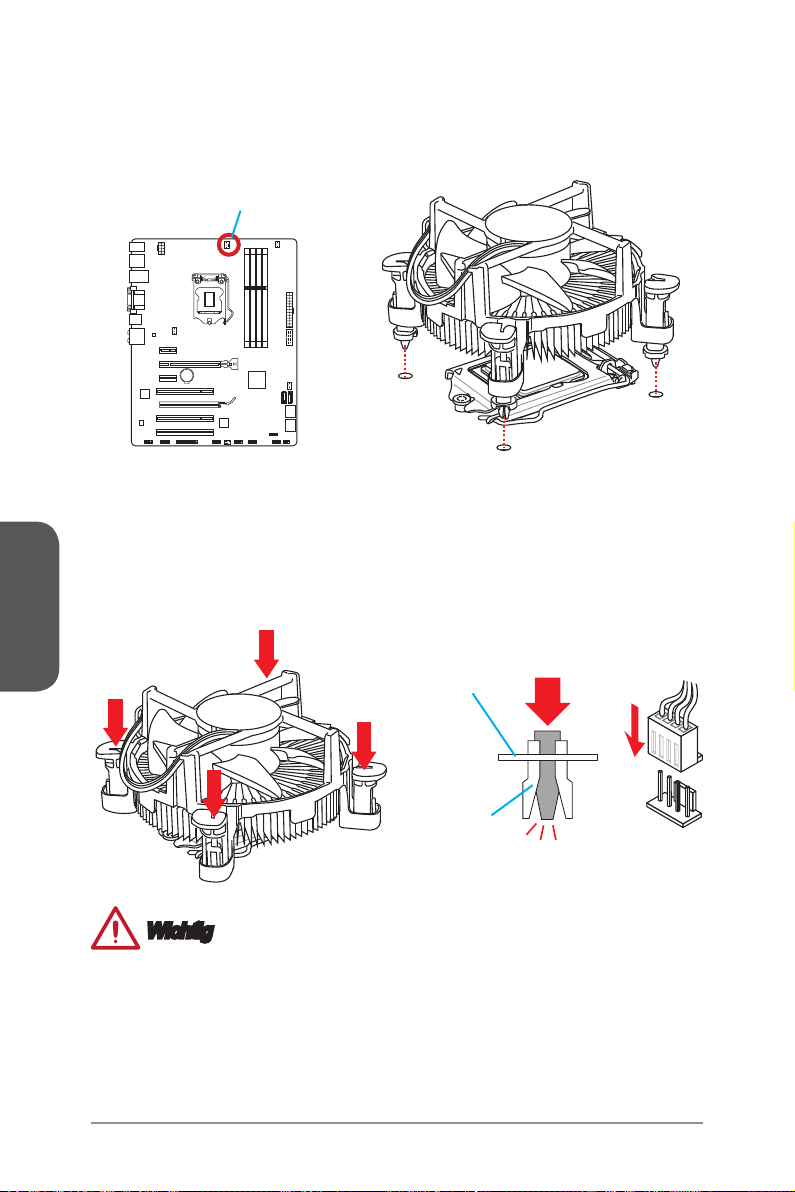
7. Machen Sie den CPU-Lüfteranschluss auf dem Motherboard ausnding.
8. Setzen Sie den Kühlkörper auf die CPU und beachten Sie die Übereinstimmung
9. Drücken Sie nach der korrekten Positionierung des Kühlkörpers die
Deutsch
10. Überprüfen Sie das Motherboard um sicherzustellen, dass das der Kühler korrekt
11. Schließlich verbinden Sie das Stromkabel des CPU Lüfters mit dem Anschluss auf
der Lüfterverankerungen mit den dafür vorgsehenen Löchern auf der Motherboard
-Platine.
CPU-Lüfteranschluss
Arretierungsstifte mit leichtem Druck nach unten bis sie einrasten. Das Einrasten
sollte mit einem klick hörbar sein.
installiert ist.
dem Motherboard.
Motherboard
Verschluss-Ende
Wichtig
Stellen Sie sicher, dass Ihr Kühlkörper eine feste Verbindung mit der CPU
•
hergestellt hat, bevor Sie Ihr System starten.
Wenn keine CPU installiert ist, schützen Sie immer den CPU-Sockel durch die
•
Plastikabdeckung.
Wenn Sie eigene CPU und den Kühlkörper/ Kühler gekauft haben, beziehen
•
Sie sich bitte auf die Unterlagen des Kühlers für mehr Details über die
Kühlerinstallation.
De-12
Page 65

Speicher
Die DIMM-Steckplätze nehmen Arbeitsspeichermodule auf. Die neusten Informationen
über kompatible Bauteile nden Sie unter http://www.msi.com/service/test-report/
DIMM1
DIMM2
DIMM3
DIMM4
Video-Demonstration
Anhand dieses Video an untenstehende Adresse lernen Sie, wie Sie
die Speichermodule installieren.
http://youtu.be/76yLtJaKlCQ
Populationsregeln für Dual-Kanal-Speicher
Im Dual-Kanal-Modus können Arbeitsspeichermodule Daten über zwei
Datenbusleitungen gleichzeitig senden und empfangen. Durch Aktivierung des DualKanal-Modus wird die Leistung Ihres Systems verbessert. Bitte beachten Sie die
folgenden Abbildungen zur Veranschaulichung der Installationsvorgaben im DualKanal-Modus.
Deutsch
DIMM2
DIMM4
DIMM1
DIMM2
DIMM3
DIMM4
Wichtig
DDR3 und DDR2 können nicht untereinander getauscht werden und der Standard
•
DDR3 ist nicht abwärtskompatibel. Installieren Sie DDR3 Speichermodule stets in
DDR3 DIMM Slots.
Verwenden Sie die Speichermodule des gleichen Typs und identischer
•
Speicherdichte im Zweikanalbetrieb, um die Systemstabilität zu gewährleisten.
Aufgrund der Chipsatzressourcennutzung wird nur eine Systemdichte bis 31+GB
•
(nicht volle 32GB) erkannt, wenn jeder DIMM Slot mit einem 8GB Speichermodul
besetzt wird.
De-13
Page 66
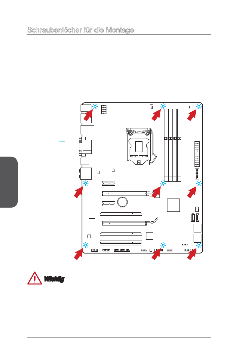
Schraubenlöcher für die Montage
Verwenden Sie die dem Motherboard beiliegende I/O-Platte und setzen Sie sie
mit leichtem Druck von innen in die Aussparung des Computergehäuses ein. Zur
Installation des Motherboards in Ihrem PC-Gehäuse befestigen Sie zunächst die
dem Gehäuse beiliegenden Abstandhalter im Gehäuse. Legen Sie das Motherboard
mit den Schraubenönungen über den Abstandhaltern und schrauben Sie das
Motherboard mit den dem Gehäuse beiliegenden Schrauben fest. Die Positionen der
Befestigungslöcher sehen Sie in der Zeichnung unten. Weitere Informationen erfahren
Sie über Ihr Gehäusehandbuch.
Deutsch
Die rückseitigen Anschlüsse des
Motherboards sollten durch die
vorgestanzten Önungen der I/O-
Platte zugänglich sein.
Wichtig
Installieren Sie das Motherboard auf einer ebenen Fläche ohne Schmutz.
•
Um Schäden am Motherboard zu verhindern, vermeiden Sie jegliche Berührung
•
des Motherboards mit dem Gehäuse mit Ausnahme der Abstandhalter unter den
Befestigungslöchern.
Stellen Sie sicher, dass sich keine losen metallischen Teile im Gehäuseinneren
•
benden.
De-14
Page 67

Stromversorgung
13 .+3 .3
V
1. +3. 3
V
14 .-1 2V
2. +3. 3
V
15 .Gr ou nd
3
.G rou nd
16 .PS -O N
#
4. +5
V
17 .Gr ou nd
5
.G rou nd
18 .Gr ou nd
6. +5
V
19 .Gr ou nd
7
.G rou nd
22 .+5
V
10 .+1 2V
20 .Re s
8. PW
R O
K
23 .+5
V
11
.+ 12V
21 .+5
V
9. 5VS B
24 .Gr ou nd
12 .+3 .3
V
7. +12 V
3.
Gr oun d
5. +12 V
1.
Gr oun d
8. +12 V
4
.G rou nd
6. +12 V
2
.G rou nd
Video-Demonstration
Anhand dieses Video an untenstehende Adresse lernen Sie, wie
Sie die Stromversorgungsstecker installieren.
http://youtu.be/gkDYyR_83I4
JPWR1~2: ATX Stromanschlüsse
Mit diesem Anschluss verbinden Sie den ATX Stromanschlusse. Achten Sie bei dem
Verbinden des ATX Stromanschlusses darauf, dass der Anschluss des Netzteils
richtig auf den Anschluss an der Hauptplatine ausgerichtet ist. Drücken Sie dann
den Anschluss des Netzteils fest nach unten, um eine richtige Verbindung zu
gewährleisten.
JPWR2
JPWR1
Wichtig
Stellen Sie sicher, dass diese Anschlüsse mit den richtigen Anschlüssen des Netzteils
verbunden werden, um einen stabilen Betrieb der Hauptplatine sicherzustellen.
De-15
Deutsch
Page 68

Erweiterungssteckplätze
Dieses Motherboard enthält zahlreiche Schnittstellen für Erweiterungskarten, wie
diskrete Grak-oder Soundkarten.
PCI_E1~E4: PCIe Erweiterungssteckplätze
Der PCIe Steckplatz unterstützt PCIe-Erweiterungskarten.
PCIe 3.0 x16-Steckplatz
PCIe 2.0 x16-Steckplatz
Deutsch
PCI1~3: PCI Erweiterungssteckplatz
Der PCI-Steckplatz kann LAN-Karten, SCSI-Karten, USB-Karten und sonstige
Zusatzkarten aufnehmen, die mit den PCI-Spezikationen konform sind.
Achten Sie darauf, dass
Steckdose herausziehen, bevor Sie eine Erweiterungskarte installieren oder entfernen.
Lesen Sie
zusätzliche Hardware oder
PCIe 2.0 x1-Steckplatz
Wichtig
Sie den Strom abschalten und
bitte auch die Dokumentation der Erweiterungskarte, um notwendige
Software-Änderungen zu überprüfen.
das Netzkabel aus der
De-16
Page 69

Video/ Grakkarten
Fall im Prozessor integriert, nutzt dieses Motherboard den im Prozessor bendlichen
Grakprozessor. Zusätzliche Grakkarten können aber über die auf dem Motherboard
verfügbaren Erweiterungssteckplätze eingesetzt werden um die Systemleistung zu
erhöhen.
Video-Demonstration
Anhand dieses Video an untenstehende Adresse lernen Sie, wie Sie
eine Grakkarte im PCIe x16 Steckplatz mit Buttery-Verschlüssen
installieren.
http://youtu.be/mG0GZpr9w_A
Installation einer Grakkarte
Stellen Sie fest für welchen Steckplatz Ihre Grakkarte geeignet ist. Suchen Sie
1.
einen entsprechenden freien Steckplatz auf Ihrem Motherboard. Entfernen Sie
eine eventuelle Schutzvorrichtung für den Steckplatz im Gehäuse.
Positionieren Sie die Grakkarte über den gewählten Steckplatz, mit dem Display-
2.
Anschluss in Richtung Gehäuseausgang. Für die Installation einer einzelnen
Grakkarte empfehlen wir PCI_E2.
Pressen Sie die Grakkarte in den Steckplatz. je nach Steckplatz sollte die Karte
3.
in einer Halterung am Steckplatzende einrasten.
Befestigen Sie das vordere Ende der Grakkarte mit einer dafür vorgesehenen
4.
Schraube am Computergehäuse.
Konsultieren Sie das Handbuch Ihrer Grakkarte für weitere Angaben zur
5.
Treiberinstallation und zu den Einstellungen. Einige Grakkarten benötigen den
Anschluss einer gesonderten Stromversorgung.
Deutsch
De-17
Page 70

Interne Anschlüsse
SATA1~6: SATA Anschluss
Dieser Anschluss basiert auf der Hochgeschwindigkeitsschnittstelle Serial ATA
(SATA). Pro Anschluss kann ein Serial ATA Gerät angeschlossen werden. Zu Serial
ATA Geräten gehören Festplatten (HDD), SSD Festplatten (SSD) und optische
Laufwerke (CD-/DVD-/Blu-Ray-Laufwerke).
Video-Demonstration
Anhand dieses Video an untenstehende Adresse
lernen Sie, wie Sie eine SATA-Featplatte installieren.
http://youtu.be/RZsMpqxythc
SATA2
SATA1
Deutsch
SATA1~6 (6Gb/s), über Intel® Z87/ H87
SATA1~4 (6Gb/s), SATA5~6 (3Gb/s) über Intel® B85
•
•
•
•
SATA4
SATA6
SATA5
SATA3
Wichtig
Viele Serial ATA Geräte benötigen eine zusätzliche Stromversorgung über das
PC-Netzteil. Dazu gehören Festplatten (SSD und HDD), und optische Laufwerke
(CD-/DVD-/ Blu-Ray). Weitere Informationen bietet das entsprechende Handbuch
des Laufwerks.
Meist müssen Serial-ATA Geräte im Gehäuse verschraubt werden. Informationen
dazu nden Sie im Gehäuse- oder Gerätehandbuch.
Knicken Sie das Serial ATA Kabel nicht in einem 90° Winkel. Datenverlust könnte
die Folge sein.
SATA-Kabel haben identische Stecker an beiden Enden. Es wird empfohlen den
achen Stecker auf dem Motherboard einstecken.
De-18
Page 71

CPUFAN1~2,SYSFAN1~3: Stromanschlüsse für Lüfter
1.Groun d
2.Speed
C
ontro
l
3.Sens
e
4.NC
1
.Ground
2.+12V
3.Sens
e
4.Speed C
ontro
l
Die Anschlüsse unterstützen aktive Systemlüfter mit +12V. Ist Ihr Motherboard mit
einem Chipsatz zur Überwachung der Systemhardware versehen, dann brauchen Sie
einen speziellen Lüfter mit Geschwindigkeitsregelung, um die Vorteile der Steuerung
des CPU Lüfters zu nutzen. Vergessen Sie nicht, alle Systemlüftern anzuschließen.
Einige Systemlüfter können nicht direkt an dem Motherboard angeschlossen werden
und müssen stattdessen mit dem Netzteil direkt verbunden werden. Kompatible
Systemlüfter können an jeder der onboard-Systemlüfteranschlüsse angeschlossen
werden.
CPUFAN1/
CPUFAN2
SYSFAN1/
SYSFAN3/
SYSFAN2
Deutsch
Wichtig
Informieren Sie sich vor dem Kühlerkauf über die empfohlenen CPU-Kühler des
•
Prozessorherstellers auf dessen website.
Die Anschlüsse unterstützen die Smart Fan Lüftersteuerung. Das Utility Command
•
Center kann installiert werden, um die Lüftergeschwindigkeit in Abhängigkeit von
der der Prozessor- und System-Temperatur zu steuern.
Für den Fall, dass nicht genügend Lüfteranschlüsse auf dem Motherboard zur
•
Verfügung stehen, können weitere Lüfter mittels Adapter direkt am Netzteil
angeschlossen werden.
Stellen Sie vor dem ersten Systemstart sicher, dass sich keine Kabel in den Lüftern
•
verfangen können.
De-19
Page 72

JFP1, JFP2: Frontpanel Anschlüsse
1. +
3.
-
10 .N o
Pi
n
5.
Re se t
S
wi tc h
HD D
LE
D
P
ow er
S
wi tc h
P
ow er
LE
D
7.
+
9. Re se rv e
d
8.
-
6.
+
4.
-
2.
+
1
.Ground
3.Suspend
LE
D
5.Power
LE
D
7.No Pi
n
8.
+
6.
-
4.
+
2.
-
Buzz er
S
peak er
Diese Anschlüsse sind für das Frontpanel angelegt. Sie dienen zum Anschluss der
Schalter und LEDs des Frontpanels. JFP1 erfüllt die Anforderungen des “Intel® Front
Panel I/O Connectivity Design Guide”. Bei der Installation des Frontpanel-Anschlüsse,
nutzen Sie bitte die beiliegenden M-Connectors um die Installation zu vereinfachen.
Schließen Sie alle Kabel aus dem PC-Gehäuse zunächst an die M-Connectors an und
stecken Sie die M-Connectors auf das Motherboard.
Anhand dieses Videos an untenstehender Adresse lernen Sie,
wie Sie die Frontpanel-Anschlüsse installieren.
http://youtu.be/DPELIdVNZUI
Deutsch
Video-Demonstration
JFP2
JFP1
Wichtig
An den Anschlüssen aus dem Gehäuse sind die positiven Kabel an den Pins, die
•
mit kleinen Dreiecken markiert sind erkennbar. Bitte verwenden Sie das Diagramm
oben und die Bezeichnungen auf den M-Connectors um die korrekte Positionierung
und Platzierung festzustellen.
Die meisten Anschlüsse in der Frontplatte des PC-Gehäuse soll vor allem in JFP1
•
gesteckt werden.
De-20
Page 73

JUSB1~2: USB 2.0 Erweiterungsanschluss
1
.
V
C
C
3
.
U
S
B
0
-
1
0
.
NC
5
.
U
S
B
0
+
7
.
G
r
o
u
n
d
9
.
N
o
P
i
n
8
.
G
r
o
u
n
d
6
.
U
S
B
1
+
4
.
U
S
B
1
-
2
.
V
C
C
5.
USB 3_ TX_ C_ DN
4
.Gr ou nd
3.U SB 3_R X_ DP
2.U SB 3_R X_ DN
1.P ow er
10. Gr oun d
9.
+
U
SB2 .0
8.
-
U
SB2 .0
7
.Gr ou nd
6.U SB 3_T X_ C_D P
20. No
Pi
n
19. Po wer
18. US B3_ RX _DN
17. US B3_ RX _DP
16. Gr oun d
15. US B3_ TX _C_ DN
14. US B3_ TX _C_ DP
13. Gr oun d
12. US B2. 0
-
11
. +
U
SB2 .0
Dieser Anschluss eignet sich für die Verbindung der Hochgeschwindigkeits- USBPeripheriegeräte, wie z.B. USB Festplattenlaufwerke, Digitalkameras, MP3-Player,
Drucker, Modems und ähnliches.
Wichtig
Bitte beachten Sie, dass Sie die mit VCC (Stromführende Leitung) und GND
•
(Erdleitung) bezeichneten Pins korrekt verbinden müssen, ansonsten kann es zu
Schäden kommen.
JUSB3: USB 3.0 Erweiterungsanschluss
Der USB 3.0 Anschluss ist abwärtskompatibel mit USB 2.0-Geräten. Unterstützt
Datentransferraten bis zu 5 Gbit/s (SuperSpeed).
Deutsch
Wichtig
Bitte beachten Sie, dass Sie die mit VCC (Stromführende Leitung) und GND
•
(Erdleitung) bezeichneten Pins korrekt verbinden müssen, ansonsten kann es zu
Schäden kommen.
Zur Verwendung eines USB 3.0-Gerät, müssen Sie das Gerät an einen USB 3.0
•
Port über ein optionales USB 3.0-kompatibles Kabel anschließen.
De-21
Page 74

JTPM1: TPM Anschluss
1
0
.
N
o
P
i
n
1
4
.
G
r
o
u
n
d
8
.
5
V
P
o
w
e
r
1
2
.
G
r
o
u
n
d
6
.
S
e
r
i
a
l
I
R
Q
4
.
3
.
3
V
P
o
w
e
r
2
.
3
V
S
t
a
n
d
b
y
p
o
w
e
r
1
.
L
P
C
C
l
o
c
k
3
.
L
P
C
R
e
s
e
t
5
.
L
P
C
a
d
d
r
e
s
s
&
d
a
t
a
p
i
n
0
7
.
L
P
C
a
d
d
r
e
s
s
&
d
a
t
a
p
i
n
1
9
.
L
P
C
a
d
d
r
e
s
s
&
d
a
t
a
p
i
n
2
1
1
.
L
P
C
a
d
d
r
e
s
s
&
d
a
t
a
p
i
n
3
1
3
.
L
P
C
F
r
a
m
e
2
.
C
I
N
T
R
U
1
.
G
r
o
u
n
d
Dieser Anschluss wird für das TPM Modul (Trusted Platform Module) ver-wendet.
Weitere Informationen über den Einsatz des optionalen TPM Modules entnehmen Sie
bitte dem TPM Plattform Handbuch.
JCI1: Gehäusekontaktanschluss
Dieser Anschluss wird mit einem Kontaktschalter verbunden. Wenn das PC-Gehäuse
geönet wird, aktiviert dies den Gehäuse-Kontaktschalter und eine Warnmeldung
Deutsch
wird auf dem Bildschirm angezeigt. Um die Warnmeldung zu löschen, muss das BIOS
aufgerufen und die Aufzeichnung gelöscht werden.
De-22
Page 75

JAUD1: Audioanschluss des Frontpanels
1.MI
C L
3.MI
C R
10.Head
P
hone
Detection
5.Head P
hone
R
7.SENSE_SEN
D
9.Head
P
hone
L
8.No
Pi
n
6.MI
C D
etection
4.NC
2
.Ground
1
0
.
G
r
o
u
n
d
1
4
.
G
r
o
u
n
d
8
.
L
P
T
_
S
L
I
N
#
1
2
.
G
r
o
u
n
d
6
.
P
I
N
I
T
#
4
.
E
R
R
#
2
.
A
F
D
#
2
4
.
G
r
o
u
n
d
2
2
.
G
r
o
u
n
d
2
6
.
N
o
P
i
n
2
0
.
G
r
o
u
n
d
1
8
.
G
r
o
u
n
d
1
6
.
G
r
o
u
n
d
1
.
R
S
T
B
#
3
.
P
R
N
D
0
5
.
P
R
N
D
1
7
.
P
R
N
D
2
9
.
P
R
N
D
3
1
1
.
P
R
N
D
4
1
3
.
P
R
N
D
5
1
5
.
P
R
N
D
6
1
7
.
P
R
N
D
7
1
9
.
A
C
K
#
2
1
.
B
U
S
Y
2
3
.
P
E
2
5
.
S
L
C
T
Dieser Anschluss ermöglicht den Anschluss von Audio Ein- und Ausgängen eines
Frontpanels. Der Anschluss entspricht den Richtlinien des “ Intel® Front Panel I/O
Connectivity Design Guide”.
JLPT1: Parallele Schnittstelle
Die Parallele Schnittstelle ist eine Standard Druckerschnittstelle, die ebenso als
Enhanced Parallel Port (EPP) und als Extended Capabilities Parallel Port (ECP)
betrieben werden kann.
Deutsch
De-23
Page 76

JCOM1: Serieller Anschluss
1
.
D
C
D
3
.
S
O
U
T
1
0
.
N
o
P
i
n
5
.
G
r
o
u
n
d
7
.
R
T
S
9
.
R
I
8
.
C
T
S
6
.
D
S
R
4
.
D
T
R
2
.
S
I
N
Es handelt sich um eine 16550A Kommunikationsschnittstelle, die 16 Bytes FIFOs
sendet/empfängt. Hier lässt sich eine serielle Maus oder andere serielle Geräte direkt
anschließen.
Deutsch
De-24
Page 77

Steckbrücken
JBAT1: Steckbrücke zur CMOS-Löschung
Der Onboard CMOS Speicher (RAM) wird durch eine externe Spannungsversorgung
durch eine Batterie auf dem Motherboard versorgt, um die Daten der
Systemkonguration zu speichern. Er ermöglicht es dem Betriebssystem, mit jedem
Einschalten automatisch hochzufahren. Wenn Sie die Systemkonguration löschen
wollen, müssen Sie die Steckbrücke für kurze Zeit umsetzen. Halten Sie sich an die
Anweisungen in der Grak, um die Daten zu löschen.
1 1
Daten beibehalten CMOS-Daten löschen
Wichtig
Wenn das System ausgeschaltet ist, können Sie die Steckbrücke stecken, um die
Daten im CMOS zu löschen. Danach entfernen Sie die Steckbrücke. Versuchen Sie
niemals die Daten im CMOS zu löschen, wenn das System eingeschaltet ist. Die
Hauptplatine kann dadurch beschädigt werden.
Deutsch
De-25
Page 78

Treiber und Dienstprogramme
Nach der Installation des Betriebssystems müssen Sie Treiber installieren, um
die Leistung des neuen Computers zu maximieren. Dem MSI Mainbaord liegt eine
Treiber-CD bei. Die enthaltenen Treiber ermöglichen es Ihnen, das Motherboard
ezienter zu nutzen und von den besonderen Eigenschaften des MSI Motherboards
zu protieren.
Sie können Ihren Computer durch den Einsatz des beiliegenden
Sicherheitsprogramms vor Viren schützen. Zusätzlich liegen dem Paket eine Vielzahl
von leistungsfähigen und nützlichen Utilities bei.
Total Installer
Total Installer ist sehr einfach zu verwenden und es gewährleistet eine zuverlässige
Installtion aller notwendigen Treiber sowie der gewünschten Programme. Befolgen
Sie bitte folgende Schritte, um die Treiber und Dienstprogramme auf Ihrem neuen
Computer zu installieren.
1.
2.
Deutsch
Lengen Sie die MSI-Treiber-Disk in das optische Laufwerk ein. Der SetupBildschirm erscheint automatisch, wenn “Autorun” aktiviert ist.
Klicken Sie auf das Symbol “Total Installer”. Ein Popup-Dialog erscheint, in dem
alle notwendigen Treiber aufgelistet werden.
Klicken Sie hier
Wählen Sie alle Kontrollkästchen der Treiber-Liste.
3.
Klicken Sie die “Install” Taste.
4.
Die Installation der Software wird dann in Gang gesetzt. Nach der Fertigstellung
5.
wird ein Neustart durchgeführt.
Klicken Sie auf OK, um den Installation zu beenden.
6.
Starten Sie den Computer neu.
7.
Sie können auch die gleiche Methode verwenden, um die gewünschten
Dienstprogramme zu installieren
.
De-26
Page 79

BIOS Setup
CLICK BIOS wurde von MSI entwickelt, es bietet eine intuitiv bedienbare grasche
Benutzeroberäche in der BIOS-Parameter einfach per Maus und Tastatur konguriert
werden können.
Mit CLICK BIOS können Benutzer alle wichtigen BIOS-Einstellungen ändern,
die CPU-Temperatur überwachen, die Boot-Reihenfolge festlegen und die
Systeminformationen anzeigen, wie CPU-Name, DRAM Kapazität, OS-Version und
BIOS-Version. Benutzer können die Einstellungen exportieren und importieren, um sie
zu sichern, einzuspielenoder mit Freunden zu teilen.
Aufruf des BIOS Setups
Nach dem Einschalten beginnt der Computer den POST (Power On Self Test Selbstüberprüfung nach Anschalten). Sobald die Meldung unten erscheint drücken Sie
die Taste <Entf>(<DEL>), um das BIOS aufzurufen:
Press DEL key to enter Setup Menu, F11 to enter Boot Menu
(ENTF drücken, um das Einstellungsprogramm zu önen;
F11 drücken um das Bootmenü zu önen)
Wenn die Nachricht verschwindet, bevor Sie reagieren und Sie möchten immer noch
ins BIOS, starten Sie das System neu, indem Sie es erst AUS- und danach wieder
ANSCHALTEN, oder die “RESET”-Taste am Gehäuse betätigen. Sie können das
System außerdem neu starten, indem Sie gleichzeitig die Tasten <Strg>,<Alt> und
<Entf> drücken (bei manchen Tastaturen <Ctrl>,<Alt> und <Del>).
MSI bietet zusätzlich zwei Methoden, um das BIOS-Setup zu gelangen. Klicken Sie
auf das Auswahlfeld “GO2BIOS” des Bildschirms "MSI Fast Boot" oder drücken Sie
die Taste “GO2BIOS" (optional) auf dem Motherboard, um beim nächsten Systemstart
automatisch ins BIOS Menu zu wechseln.
Deutsch
Klicken Sie auf das
Auswahlfeld "GO2BIOS" des
Bildschirms "MSI Fast Boot".
Wichtig
Beim Einsatz des “MSI Fastboot”-Dienstprogramms zum automatischen Aufrufen
•
des BIOS müssen Sie das Programm zunächst installieren.
Die Menüpunkte jeder in diesem Kapitel beschriebenen BIOS Kategorie benden
•
sich in permanenter Weiterentwicklung um die Systemleistung zu verbessern.
Deswegen können die Beschreibungen leicht von der letzten Fassung des BIOS
abweichen und sollten demnach nur als Anhaltspunkte dienen.
De-27
Page 80

Überbilck
Nach dem Aufrufen des BIOS, sehen Sie die folgende Anzeige.
Genie Taste
BIOS-Menü-
Deutsch
▶
Es zeigt die Temperatur des Prozessors und des Motherboards.
▶
Hier können Sie die Sprache der BIOS-Einstellungen auswählen.
▶
Es zeigt Zeit, Datum, CPU-Name, CPU-Frequenz, DRAM-Frequenz, DRAM-Kapazität
und die BIOS-Version.
▶
Die folgenden Optionen stehen zur Verfügung:
Temperatur-überwachung
Modell
Name
Virtual OC
Auswahl
Menüanzeige
Temperatur-überwachung
Sprache
System-Information
BIOS-Menü-Auswahl
SETTINGS - Mit diesem Menü können Sie die Parameter für Chipsatz, Boot-
■
Geräte angeben.
OC - Dieses Menü enthält die Frequenz- und Spannungsanpassungen. Die
■
Erhöhung der Frequenz kann eine bessere Leistung erreichen. Andererseits
kann eine zu hohe Frequenz und hohe Wärmeentwicklung Instabilität
verursachen. Daher empfehlen wir unerfahrenen Anwendern nicht zu
übertakten.
M-FLASH - Dieses Menü bietet die Funktion, das BIOS mit einem USB-Flash-
■
Laufwerk zu aktualisieren.
OC PROFILE -In diesem Menü werden die verschiedenen Overclocking-
■
Prole gesetzt.
HARDWARE MONITOR - In diesem Menü werden die Geschwindigkeiten der
■
Lüfter gesetzt und die Spannungen des Systems überwacht.
BOARD EXPLORER - In diesem Menü zeigt die Information der installierten
■
Geräte auf dem Motherboard an.
Sprache
System-
Information
Bootgeräte-
Prioritäts-
leiste
BIOS-Menü-
Auswahl
De-28
Page 81

Boot-Geräte Prioritätsleiste
▶
Sie können die Gerätesymbole verschieben, um die Startreihenfolge zu ändern.
Hohe Priorität Niedrigere Priorität
Menüanzeige
▶
Dieser Bereich ermöglicht die Konguration von BIOS Einstellungen.
Virtual OC Genie Taste
▶
Aktivieren oder deaktivieren Sie die OC Genie Funktion durch einen Klick auf diese
Taste. Wenn aktiviert, leuchtet diese Taste auf. Aktivieren Sie die OC Genie-Funktion
mit einem von MSI optimierten Übertaktungsprol automatisch zu übertakten.
Wichtig
Es wird empfohlen, keine Änderung im OC-Menü zu machen und die
•
Werkseinstellungen nach dem Aktivieren der OC Genie-Funktion nicht zu laden.
Im OC Genie Modus sind das BIOS-Update oder ein Clearing-CMOS unzulässig.
•
Diese können zum Versagen der OC Genie Funktion oder zu anderen Eekten
führen.
Modell Name
▶
Zeigt das Modell des Motherboards an.
Allgemeine Hilfe
Deutsch
Untermenü Bildlaueiste
Untermenü
▶
Wenn Sie an der linken Seite bestimmter Felder ein Dreieckssymbol nden, bedeutet
dies, dass Sie über das entsprechende Feld ein Untermenü mit zusätzlichen Optionen
aufrufen können. Durch die Steuertasten oder Maus können Sie ein Feld hervorheben
und durch Drücken der Eingabetaste <Enter> oder durch einen Doppelklick mit der
linken Maustaste in das Untermenü gelangen.
Bildlaueiste
▶
Schieben Sie die Bildlaueiste oder nutzen die Pfeiltasten, um die weiteren Elemente
anzuzeigen, die im “Menü” Anzeige-Bereich sind.
Allgemeine Hilfe
▶
Die Allgemeine Hilfe zeigt eine Kurzbeschreibung an, um Ihnen bei der Verwendung
des ausgewählten Elements zu helfen.
De-29
Page 82

Betrieb
Sie können die BIOS-Einstellungen mit der Maus oder der Tastatur steuern. Die
folgende Tabelle zeigt und beschreibt die Hotkeys und Mausaktionen.
Hotkey Maus Beschreibung
<↑↓→← >
Auswahl eines Eintrages
Deutsch
Bewegen Sie den
Cursor
<Enter>
Klicken/ doppeltklicken Sie mit der
linken Maustaste
<Esc>
Klicken Sie mit der
rechten Maustaste
<+> Hochzählen oder ändern eines Wertes
<-> Herunterzählen oder ändern eines Wertes
<F1> Allgemeine Hilfe
<F4> CPU-Spezikationen
<F5> Aufruf des Memory-Z Fensters mit Details zum
<F6> Laden der ursprünglichen Setup-Standardwerte
<F8> OC-Prol wird vom USB-Stick geladen
<F9> OC-Prol wird auf einem USB-Stick gespeichert
<F10> Speichern oder Zurücksetzen der Änderungen
<F12> Speichern des Bildschirmfotos auf einen FAT/
.
Auswahl eines Symbols/ Feldes
Das Menü verlassen oder zurück zum
Hauptmenü aus dem Untermenü
Speicher
FAT32 USB-Laufwerk
De-30
Page 83

OC-Menü
In diesem Menü können Benutzer das BIOS anpassen und übertakten. Bitte führen
Sie nur Änderungen durch, wenn Sie sich über das Ergebniss im Klaren sind. Sie
sollten Erfahrung beim Übertakten haben, da Sie sonst das Motherboard oder
Komponenten des Systems beschädigen können.
Wichtig
Die Übertaktung ist nur für fortgeschrittene Benutzer zu empfehlen.
•
Die erfolgreiche Übertaktung ist nicht gewährleistet. Die Anwendung von
•
Übertaktungsmaßnahmen kann zu Verlust der Garantie oder zur Beschädigung der
Hardware führen.
Falls Sie sich mit der Übertaktung nicht auskennen, empfehlen wir für einfaches
•
Übertakten die OC-Genie Funktion.
Deutsch
Current CPU/ DRAM/ Ring Frequency
▶
Zeigt die derzeitigen Frequenz der installierten CPU, Speicher und Ring. Dies ist
nur eine Anzeige – keine Änderung möglich.
CPU Base Clock (MHz) [Default]
▶
Hier können Sie den CPU Grundtakt anpassen. Sie können die CPU übertakten,
indem Sie diesen Wert verändern. Bitte beachten Sie, dass die Übertaktung (und das
Ergebnis) und die Stabilität nicht gewährleistet sind. Diese Option wird angezeigt, wenn
der installierte Prozessor diese Funktion unterstützt.
Current CPU Base Clock Strap (Z87-G43)
▶
Zeigt das derzeitigen Band des CPU Grundtakts an. Dies ist nur eine Anzeige – keine
Änderung möglich. Diese Option kann nur geändert werden, wenn der Prozessor diese
Funktion unterstützt.
De-31
Page 84

▶
Legen Sie das Band des CPU Grundtakts fest. Sie können den CPU Grundtakt durch
die Anpassung des Werts übertakten. Bitte beachten Sie, dass die Übertaktung (und
das Ergebnis) und die Stabilität nicht gewährleistet sind. Diese Option kann nur
geändert werden, wenn der Prozessor diese Funktion unterstützt. Wenn die Einstellung
auf [Auto] gesetzt ist, wird das BIOS diese Einstellungen automatisch kongurieren.
[Optionen: Auto, 1,00, 1,25, 1,67]
▶
Einstellung des angepassten CPU Grundtakts.
[Auto] Diese Einstellungen werden vom BIOS automatisch konguriert.
[Next Boot] Die CPU arbeitet mit angepasstem CPU Grundtakt nach einem
[Immediate] Die CPU arbeitet mit angepasstem CPU Grundtakt sofort.
▶
Wählen Sie einen PLL-Modus (Phase Lock Loop) für die CPU PCIe aus. Diese Option
wird angezeigt, wenn die installierte CPU diese Einstellungen unterstützt.
[Auto] Diese Einstellungen werden vom BIOS automatisch konguriert.
[LC PLL] Aktivieren Sie LC PLL für normale Zwecke.
[SB PLL] Aktivieren Sie SB PLL für extreme Übertaktungen.
▶
Aktivieren oder deaktivieren Sie den Filter PLL für die CPU. Diese Option wird angezeigt,
Deutsch
wenn die installierte CPU diese Einstellungen unterstützt.
[Auto] Diese Einstellungen werden vom BIOS automatisch konguriert.
[Enabled] Es bietet eine große Auswahl vom Grundtakt zur Übertaktung durch
[Disabled] Es bietet eine normale Auswahl vom Grundtakt.
▶
Wählen Sie den Betriebsmodus des CPU-Multiplikators.
[Auto] Diese Einstellungen werden vom BIOS automatisch konguriert.
[Fixed Mode] Legt den CPU-Multiplikator fest.
[Dynamic Mode] Der CPU-Multiplikator wird dynamisch je nach CPU-Belastung
▶
Legen Sie den CPU-Multiplikator fest, um die CPU-Taktfrequenzen zu bestimmen. Diese
Option kann nur geändert werden, wenn der Prozessor diese Funktion unterstützt.
▶
Es zeigt die eingestellte Frequenz der CPU an. Es handelt sich um eine Anzeige –
Änderungen sind nicht möglich.
▶
Aktivieren oder deaktivieren Sie die Enhanced Intel® SpeedStep Technologie.
[Enabled] Aktiviert EIST, um die CPU-Spannung und Taktfrequenz dynamisch
[Disabled] Deaktiviert EIST.
Adjust CPU Base Clock Strap [Auto] (Z87-G43)
CPU Base Clock Apply Mode [Auto]
Neustart.
CPU PCIE PLL [Auto] (Z87-G43)
Filter PLL [Auto] (Z87-G43)
Setzen eines höheren Werts.
CPU Ratio Mode [Auto]
verändert.
Adjust CPU Ratio [Auto]
Adjusted CPU Frequency
EIST [Enabled]
anzupassen. Es kann zu verringern durchschnittliche Stromverbrauch
und die durchschnittliche Wärmeproduktion.
De-32
Page 85

Intel Turbo Boost [Enabled]
▶
Aktivieren oder deaktivieren Sie Intel® Turbo Boost. Diese Option wird angezeigt, wenn
die installierte CPU diese Einstellungen unterstützt.
[Enabled] Aktivieren Sie diese Funktion, um die CPU-Leistung automatisch zu
[Disabled] Deaktivieren Sie diese Funktion.
Enhanced Turbo [Auto]
▶
Aktivieren oder deaktivieren Sie die Enhanced Turbo Funktion für alle CPU-Kerne die
CPU-Leistung zu erhöhen.
[Auto] Diese Einstellungen werden vom BIOS automatisch konguriert.
[Enabled] Alle CPU-Kerne werden mit maximalem Turbo konguriert.
[Disabled] Deaktivieren Sie diese Funktion.
Adjust Ring Ratio [Auto]
▶
Setzen Sie den Ring Ratio. Der erlaubte Wertebereich ist abhängig von der installierten
CPU.
Adjusted Ring Frequency
▶
Zeigt die angepasste Ring Frequenz. Nur Anzeige – keine Änderung möglich.
Adjust GT Ratio [Auto]
▶
Setzen Sie den Multiplikator der integrierten Grak. Der erlaubte Wertebereich ist
abhängig von der installierten CPU.
Adjusted GT Frequency
▶
Zeigt die angepasste Frequenz der integrierten Grak. Nur Anzeige – keine Änderung
möglich.
DRAM Reference Clock [Auto]
▶
Setzen Sie den DRAM-Referenztakt. Der erlaubte Wertebereich ist abhängig von
der installierten CPU. Diese Option wird angezeigt, wenn die installierte CPU diese
Einstellungen unterstützt.
DRAM Frequency [Auto]
▶
Setzen Sie die DRAM Frequenz. Bitte beachten Sie, dass ein zuverlässiges
Übertaktungsverhalten nicht garantiert werden kann.
Adjusted DRAM Frequency
▶
Zeigt die Speicherfrequenz an. Nur Anzeige – keine Änderung möglich.
Extreme Memory Prole (X.M.P) [Disabled]
▶
Extreme Memory Proles (XMP) sind von Intel eingeführte Zertizierungen für DDR3-
Speichermodule aus dem PC-Bereich und können Sie kompatiblen DDR3-Speicher
übertakten. Diese Option steht zur Verfügung, wenn die installierten Speichermodule
die XMP Technik unterstützen.
[Disabled] Deaktiviert diese Funktion.
[Prole 1] Sie können ihre Plattform übertakten, indem sie das Prole1 auswählen
[Prole 2] Sie können ihre Plattform übertakten, indem sie das Prole2 auswählen
erhöhen, wenn das System mehr Leistung benötigt.
Deutsch
De-33
Page 86

▶
Wählt den Speicher-Timing-Modus aus.
[Auto] Das DRAM-Timing wird basierend auf SPD (Serial Presence Detect) der
[Link] Ermöglicht die manuelle Kongurieren des DRAM-Timing für alle
[UnLink] Ermöglicht die manuelle Kongurieren des DRAM-Timing für die
▶
Drücken Sie die Eingabetaste <Enter>, um das Untermenü aufzurufen. Dieses Untermenü
wird nach der Einstellung [Link] oder [Unlink] in “DRAM Timing Mode” aktiviert werden.
Der Anwender kann die Speicher-Timing für jeden Kanal des Speichers einstellen. Das
System könnte nach dem Ändern Speicher-Timings instabil werden oder nicht mehr
booten. Wenn Instabilität auftritt, löschen Sie bitte die CMOS-Daten und stellen Sie
die Standardeinstellungen wieder her. (Lesen Sie bitte den Abschnitt "Clear CMOS
Jumper/ Taste", um die CMOS-Daten zu löschen, und die Standardeinstellungen auf
das BIOS zu laden.)
▶
Drücken Sie die Eingabetaste <Enter>, um das Untermenü aufzurufen. Aktiviert oder
deaktiviert die verschiedenen Methoden des DRAM-Trainings. Das System könnte
nach Änderungen dieser Elemente in diesem Untermenü instabil werden oder nicht
mehr booten. Wenn Instabilität auftritt, löschen Sie bitte die CMOS-Daten und stellen
Deutsch
Sie die Standardeinstellungen wieder her. (Lesen Sie bitte den Abschnitt "Clear CMOS
Jumper/ Taste", um die CMOS-Daten zu löschen, und die Standardeinstellungen auf
das BIOS zu laden.)
▶
Aktivieren oder deaktivieren Sie die die Initiierung und Prüfung des Speichers für
jeden.
[Auto] Diese Einstellungen werden vom BIOS automatisch konguriert.
[Enabled] Der Vorgang der Initierung und Prüfung des Hauptspeichers wird
[Disabled] Der Speicher wird bei jedem Boot-Vorgang vollständig neu initiiert und
▶
Drücken Sie die Eingabetaste <Enter>, um das Untermenü aufzurufen. Steuert die
digitale CPU PWM.
DRAM Timing Mode [Auto]
installierten Speichermodule bestimmt.
Speicherkanäle.
einzelnen Speicherkanäle.
Advanced DRAM Conguration
DRAM Training Conguration
Memory Fast Boot [Auto]
aus dem Archiv der ersten Initiierung imitiert um den Systemstart zu
beschleunigen.
geprüft.
DigitALL Power
CPU Phase Control [Auto]
▶
Steueren Sie PWM Phase proportional zur CPU-Belastung. Wenn die Einstellung
auf [Auto] gesetzt ist, wird das BIOS die CPU PWM-Phase automatisch optimieren.
[Auto] Diese Einstellungen werden vom BIOS automatisch konguriert.
[Disabled] Deaktiviert die PWM-Phase Switching Funktion.
CPU Vdroop Offset Control [Auto]
▶
Legen Sie einen Prozentsatz der Oset-Spannung für die CPU VDroop fest. Wenn
die Einstellung auf [Auto] gesetzt ist, wird das BIOS diese Einstellung automatisch
kongurieren. [Optionen: Auto, +12,5%, +25%, +37,5%, +50%, +62,5%, +75%,
+87,5%, +100%]
De-34
Page 87

CPU Over Voltage Protection [Auto]
▶
Legen Sie die Spannungsgrenze für den CPU-Überspannungsschutz fest. Wenn die
Einstellung auf [Auto] gesetzt ist, wird das BIOS diese Einstellungen automatisch
kongurieren. Höhere Spannung bietet weniger Sicherheit und kann das System
beschädigen.
CPU Under Voltage Protection [Auto]
▶
Legen Sie die Spannungsgrenze für den CPU-Unterspannungsschutz fest. Wenn
die Einstellung auf [Auto] gesetzt ist, wird das BIOS diese Einstellungen automatisch
kongurieren. Höhere Spannung bietet weniger Schutz und kann das System
beschädigen.
CPU Over Current Protection [Auto]
▶
Legen Sie den aktuellen Grenzwert für den CPU-Überstromschutz fest. Wenn die
Einstellung auf [Auto] gesetzt ist, wird das BIOS diese Einstellungen automatisch
kongurieren Höhere Spannung bietet weniger Sicherheit und kann das System
beschädigen.
Phase Over Current Protection [Enabled]
▶
Aktiviert oder deaktiviert die Phase Überstromschutz.
[Enabled] Setzen Sie den aktuellen Grenzwert in den Phase für
[Disabled] Deaktiviert diese Funktion
CPU Switching Frequency [Auto]
▶
Stellen Sie die PWM Arbeitsgeschwindigkeit ein, um die CPU Core-Spannung und
den Ripple Bereich zu stabilisieren. Die Erhöhung der PWM Arbeitsgeschwindigkeit
verursachen höhere Temperatur der MOSFET. So stellen Sie bitte sicher, dass eine
Kühllösung für MOSFET gut vorbereitet, bevor Sie den Wert erhöhen. Wenn die
Einstellung auf [Auto] gesetzt ist, wird das BIOS diese Einstellungen automatisch
kongurieren.
CPU VRM Over Temperature Protection [Enabled]
▶
Aktivieren oder deaktivieren Sie den CPU VRM Übertemperaturschutz.
[Enabled] Setzen Sie für den Übertemperaturschutz die Temperaturgrenze auf
[Disabled] Deaktiviert diese Funktion.
Digital Compensation Level [Auto]
▶
Stellen Sie die aktuelle Geschwindigkeit Entschädigung ein, wenn die MOS-
Phasen geändert werden. Wenn die Einstellung auf [Auto] gesetzt ist, wird
das BIOS diese Einstellungen automatisch kongurieren. Die erhöhte Höhere
Entschädigungen bietet eine bessere Leistung auf den gegenwärtigen Stabilität
während der Übertaktung.
Imon Overwrite [Auto]
▶
Stellen Sie den Imon Strom für die CPU.
[Auto] Diese Einstellungen werden vom BIOS automatisch konguriert.
[Quarter] Setzen Sie den Imon Strom in Quartal.
[Half] Setzen Sie den Imon Strom in Hälften.
[Disabled] Setzen Sie den Standard-Wert für den Imon Strom.
Überstromschutz.
.
CPU VRM.
Deutsch
De-35
Page 88

▶
Aktivieren oder deaktivieren Sie die SVID (Serial Voltage Identication)-Unterstützung.
[Auto] Diese Einstellungen werden vom BIOS automatisch konguriert.
[Enabled] PWM-Phase wird dynamisch je nach CPU SVID (Serial Voltage
[Disabled] Deaktiviert die SVID (Serial Voltage Identication)-Unterstützung.
▶
Legen Sie die CPU Eingangsspannung fest. Die CPU Eingangsspannung ist die CPU
Stromquelle, die durch Komponenten der CPU gemeinsam genutzt wird.
▶
Zeigt die aktuelle CPU VCCIN Spannung an. Nur Anzeige.
▶
Wählen Sie die Betriebmodi für diese Spannungen aus.
[Auto] Diese Einstellungen werden vom BIOS automatisch konguriert.
[Adaptive Mode] Legt die adaptiven Spannungen automatisch an zur Optimierung
Deutsch
[Override Mode] Hier können Sie diese Spannungen manuell einstellen.
▶
Einstellung dieser Spannungen. Wenn die Einstellung auf [Auto] gesetzt ist, wird das
BIOS die Spannungen automatisch eingestellt oder Sie können es manuell einstellen.
▶
Oset Mode/ CPU SA Voltage Oset Mode/ CPU IO Analog Voltage Oset Mode/ CPU
IO Digital Voltage Oset Mode [Auto]
Wählen Sie die Spannungs-Oset-Modi aus.
[Auto] Diese Einstellungen werden vom BIOS automatisch konguriert.
[+] Hier können Sie die positive Oset-Spannung einstellen.
[-] Hier können Sie die negative Oset-Spannung einstellen.
▶
Voltage Oset/ CPU IO Analog Voltage Oset/ CPU IO Digital Voltage Oset [Auto]
Stellen Sie die Oset-Werte für diese Spannungen ein.
▶
Current CPU SA Voltage/ Current CPU IO Digital Voltage
Zeigt die aktuellen Spannungen. Nur Anzeige.
Transient Boost [Disabled]
▶
Aktivieren oder deaktivieren Sie die vorübergehende Erhöhung.
[Enabled] Aktivieren Sie diese Funktion, um das System in einen stabilen
[Disabled] Deaktiviert diese Funktion.
SVID Communication [Auto]
VCCIN Voltage [Auto]
Current VCCIN Voltage
CPU Core Voltage Mode/ CPU Ring Voltage Mode/ CPU GT Voltage Mode [Auto]
CPU Core Voltage/ CPU Ring Voltage/ CPU GT Voltage [Auto]
CPU Core Voltage Oset Mode/ CPU Ring Voltage Oset Mode/ CPU GT Voltage
CPU Core Voltage Oset/ CPU Ring Voltage Oset/ CPU GT Voltage Oset/ CPU SA
Current CPU Core Voltage/ Current CPU Ring Voltage/ Current CPU GT Voltage/
Zustand bei hoher Systemlast zu führen.
Identication) geändert.
der System-Performance.
De-36
Page 89

Internal VR OVP OCP Protection [Auto]
▶
Aktiviert oder deaktiviert Sie den Überspannungsschutz und Überstromschutz für den
CPU internen Spannungsregulator (VR/ Voltage Regulator).
[Auto] Diese Einstellungen werden vom BIOS automatisch konguriert.
[Enabled] Legt die Spannungsbegrenzung der CPU internen VR für
[Disabled] Deaktivieren Sie diese Funktion zum Übertakten.
Internal VR Eciency Management [Auto]
▶
Aktiviert oder deaktiviert das internen CPU-VR Ezienzmanagement.
[Auto] Diese Einstellungen werden vom BIOS automatisch konguriert.
[Enabled] Aktivierung des VR Ezienzmanagements für Energieersparnis.
[Disabled] Deaktivierung dieser Funktion.
DRAM Voltage [Auto]
▶
Setzen die Speicherspannung. Wenn die Einstellung auf [Auto] gesetzt ist, wird das
BIOS die Speicher-Spannung automatisch einstellen. Sie können die Einstellungen
auch manuell vornehmen.
Current DRAM Voltage
▶
Zeigt die aktuelle Speicherspannung. Nur Anzeige.
DDR_VREF_CA/ DDR_VREF_DQ_A/ DDR_VREF_DQ_B/ PCH 1.05 Voltage/ PCH
▶
1.5 Voltage
Einstellung dieser Spannungen. Wenn die Einstellung auf [Auto] gesetzt ist, wird das
BIOS die Speicher-Spannung automatisch einstellen. Sie können die Einstellungen
auch manuell vornehmen.
Current PCH 1.05 Voltage
▶
Zeigt die aktuelle PCH 1.05 Spannung. Nur Anzeige.
CPU Memory Changed Detect [Enabled]
▶
Aktivierung oder Deaktivierung der Systemwarnmeldung beim Booten, wenn die CPU
oder Hauptspeicher ersetzt wurde.
[Enabled] Das System zeigt eine Warnmeldung beim Systemstart und lädt die
[Disabled] Deaktivierung der Funktion und Beibehaltung der aktuellen BIOS-
Spread Spectrum
▶
Die Spread Spectrum Funktion reduziert die erzeugte elektromagnetischen Strahlung,
mittels Modulation eines Taktgeneratorimpulses.
[Enabled] Aktivieren Sie die Spread-Spectrum-Funktion, um die elektromagnetische
[Disabled] Verbesseren Sie die Übertaktungs-Fähigkeiten des CPU-Grundtakts.
Überspannungsschutz und Überstromschutz.
Default-Einstellungen für neue Geräte.
Einstellungen.
Wechselwirkung zu reduzieren.
Deutsch
Wichtig
Sollten Sie keine Probleme mit Interferenzen haben, belassen Sie es bei der
•
Einstellung [Disabled] (ausgeschaltet) , um bestmögliche Systemstabilität und
-leistung zu gewährleisten. Stellt für sie EMI ein Problem dar, wählen Sie die
gewünschte Bandbreite zur Reduktion der EMI.
De-37
Page 90

•
•
▶
Drücken Sie die Eingabetaste <Enter>, um das Untermenü aufzurufen. Das Untermenü
zeigt die Informationen installierte CPU an. Zu diesen Informationen gelangen Sie,
indem Sie die Taste [F4] drücken. Nur Anzeige.
▶
Drücken Sie die Eingabetaste <Enter>, um das Untermenü aufzurufen. Dieses
Untermenü zeigt alle Einstellungen und Timings des installierten Speichers. Zu diesen
Informationen gelangen Sie auch, indem Sie die Taste [F5] drücken.
Deutsch
▶
Drücken Sie die Eingabetaste <Enter>, um das Untermenü aufzurufen.
Je größer der Spread Spectrum Wert ist, desto größer nimmt der EMI ab, und das
System wird weniger stabil. Bitte inormieren Sie sich über die lokale EMI Regelung
und den passenden Spread Spectrum Wert.
Denken Sie daran Spread Spectrum zu deaktivieren, wenn Sie übertakten, da sogar
eine leichte Schwankung eine vorübergehende Taktsteigerung erzeugen kann, die
gerade ausreichen mag, um Ihren übertakteten Prozessor in seiner Funktion zu
stören.
CPU Specications
CPU Technology Support
▶
Drücken Sie die Eingabetaste <Enter>, um das Untermenü aufzurufen. Das
Untermenü zeigt die wichtigsten Eigenschaften der installierten CPU an.
MEMORY-Z
DIMM1~4 Memory SPD
▶
Drücken Sie die Eingabetaste <Enter>, um das Untermenü aufzurufen. Das
Untermenü zeigt die Technologien des verwendeten Speichers an. Nur Anzeige.
CPU Features
Hyper-Threading Technology [Enabled]
▶
Der Prozessor verwendet die Technologie des Hyper-Threadings, um die
Transaktionsraten zu erhöhen und die Antwortzeiten des Benutzers zu verringern.
Die Intel Hyper-Threading Technologie behandelt die Prozessorkerne innerhalb des
Prozessors als Multi logische Prozessoren, die Anweisungen simultan durchführen
können. Dadurch tritt eine wesentliche Verbesserung der Systemleistung ein.
[Enable] Aktiviert die Intel Hyper-Threading Technologie.
[Disabled] Deaktiviert die Option, wenn das System die HT-Funktion nicht
Active Processor Cores [All]
▶
Hier können Sie die Zahl der aktiven Prozessorkerne auswählen.
Limit CPUID Maximum [Disabled]
▶
Aktiviert oder deaktiviert den erweiterten CPUID-Wert.
[Enabled] Das BIOS begrenzt den maximalen CPUID Eingabewert, um
[Disabled] Verwenden Sie den maximalen CPUID Eingabewert.
unterstützt.
Bootprobleme mit älteren Betriebssystem zu umgehen, die den
Prozessor mit erweiterten CPUID-Wert nicht unterstützen.
De-38
Page 91

Execute Disable Bit [Enabled]
▶
Intel’s Execute Disable Bit kann an den Rechner gerichtete “Buer Overow” Angrie
verhindern, bei denen Computer-Würmer versuchen, das System durch Ausführung
von Codes zu schädigen. Es wird empfohlen, diese Funktion zu aktivieren.
[Enabled] Aktiviert den NO-Execution Schutz, um bösartigen Angrie und
[Disabled] Deaktiviert diese Funktion.
Intel Virtualization Tech [Enabled]
▶
Aktiviert oder deaktiviert die Intel Virtualization Technologie.
[Enabled] Aktiviert die Intel Virtualization-Technologie, die es mehreren
[Disabled] Deaktiviert diese Funktion.
Hardware Prefetcher [Enabled]
▶
Aktivieren oder deaktivieren Sie das Hardware Prefetcher (MLC Streamer
prefetcher).
[Enabled]
[Disabled]
Adjacent Cache Line Prefetch [Enabled]
▶
Aktiviert oder deaktiviert den CPU Hardware Prefetcher (MLC Spatial prefetcher).
[Enabled] Ermöglicht Adjacent Cache Line Prefetch zur Verringerung der Cache
[Disabled] Aktiviert nur die angeforderten Cache-Zeilen.
CPU AES Instructions [Enabled]
▶
Aktiviert oder deaktiviert die CPU AES (Advanced Encryption Standard-New
Instructions) Unterstützung. Diese Option wird angezeigt, wenn die CPU diese
Funktion unterstützt.
[Enabled] Aktiviert die Intel AES Unterstützung.
[Disabled] Deaktiviert die Intel AES Unterstützung.
Intel Adaptive Thermal Monitor [Enabled]
▶
Aktiviert oder deaktiviert die Intel Adaptive Thermal-Monitor-Funktion, um die CPU
vor Überhitzung zu schützen.
[Enabled] Drosselt die CPU Kerntakt, wenn die CPU-Temperatur über die
[Disabled] Deaktiviert diese Funktion.
Intel C-State [Auto]
▶
C-State ist eine durch ACPI denierte Prozessor-Power-Management-Technologie.
[Auto] Diese Einstellungen werden vom BIOS automatisch konguriert.
[Enabled] Ermöglicht die Erkennung, wann sich
[Disabled] Deaktiviert diese Funktion.
Würmern abzuwehren.
Betriebssystemen ermöglicht in voneinander unabhängigen
Partitionen zu arbeiten. Das System kann als mehrere Systeme
virtuell einsetzen.
Der CPU Hardware Prefetcher kann frühzeitig Daten und Anweisungen
aus dem Speicher in den L2-Cache aden um die Cache-Latency
Zeiten zu reduzieren.
Deaktiviert den Hardware Prefetcher.
Latenzzeit und zur Leistungssteigerung von Applikationen.
adaptive Temperatur steigt.
das System im Leerlauf bendet
und senkt den CPU-Stromverbrauch entsprechend.
Deutsch
De-39
Page 92

Deutsch
C1E Support [Disabled]
▶
Aktiviert oder deaktiviert die C1E-Funktion für Stromersparnis im Leerlauf. Diese
Option wird angezeigt, wenn “Intel C-State” aktiviert ist.
[Enabled] Ermöglicht die C1E Funktion, um die CPU-Frequenz und Spannung
[Disabled] Deaktiviert diese Funktion.
Package C State limit [Auto]
▶
Hier können Sie einen CPU C-State-Modus für Stromsparen auswählen, wenn das
System im Leerlauf ist. Diese Option wird angezeigt, wenn "Intel C-State" aktiviert
ist.
[Auto] Diese Einstellungen werden vom BIOS automatisch konguriert.
[C0~C7s] Die Energiesparstufe ist von hoch zu niedrig ist C7, C7, C6, C3, C2,
[No limit] Es gibt keinen C-state Grenzwert für die CPU.
LakeTiny Feature [Disabled]
▶
Aktivieren oder deaktivieren Sie die Intel See Tiny-Technologie mit IRST für SSD.
Diese Option wird angezeigt, wenn eine installierte CPU diese Funktion unterstützt
und “Intel C-State” aktiviert ist.
[Enabled] Verbessert die der dynamischen IO-Last angepasste Leistung für die
[Disabled] Deaktiviert diese Funktion.
Hinweis: Die folgenden Elemente werden angezeigt, wenn Intel Turbo Boost aktiviert
Long Duration Power Limit (W) [Auto]
▶
Hier stellen Sie die TDP Leistungsgrenze für die CPU in Turbo Boost Modus ein.
Long Duration Maintained (s) [Auto]
▶
Hier stellen Sie den Zeitraum (ms) für die TDP Leistungsgrenze (W) ein.
Short Duration Power Limit (W) [Auto]
▶
Hier stellen Sie die TDP Leistungsgrenze für CPU in Turbo Boost Modus ein.
CPU Current limit (A) [Auto]
▶
Hier legen Sie die maximale Stromgrenze der CPU im Turbo Boost Modus fest.
Wenn der Strom über den angegebenen Grenzwert steigt, verringert die CPU
automatisch Core-Frequenz.
1/2/3/4-Core Ratio Limit [Auto]
▶
Diese Option erscheint nur, wenn eine CPU installiert ist, die diese Funktion
unterstützt. Hier können Sie den CPU Multiplikator in den verschiedenen aktiven
Kernen im Turbo Boost Modus einstellen. Diese Option wird angezeigt, wenn der
installierte Prozessor diese Funktion unterstützt.
zur Stromersparnis im Leerlauf zu reduzieren.
dann C0.
Beschleunigung der SSD Geschwindigkeit.
ist.
De-40
Page 93

Français
Merci d’avoir choisi une carte mère ATX de la série Z87-G43/ H87-G43/
B85-G43 (MS-7816 v1.X). La série Z87-G43/ H87-G43/ B85-G43 est basée
sur le chipset Intel® Z87/ H87/ B85 pour une ecacité optimale. Conçue pour
fonctionner avec les processeurs Intel® LGA1150, les cartes mères de la série
Z87-G43/ H87-G43/ B85-G43 délivrent de hautes performances et orent une
solution adaptée tant aux professionnels qu’aux particuliers.
Page 94

Spécications
Français
Processeurs Processeurs 4ème Génération Intel® Core™ i7 / Core™ i5 /
Chipset Chipset Intel® Z87 Express (Z87-G43)
Mémoire
supportée
Emplacement
d’extension
Graphiques
intégrées
Multi-GPU
Support
Stockage Chipset Intel Z87/ H87/ B85 Express
USB Chipset Intel Z87/ H87/ B85 Express
Audio Realtek® ALC892 Codec
LAN 1x contrôleur Realtek® 8111E Gigabit LAN■
■
Core™ i3 / Pentium® / Celeron® pour socket LGA 1150
■
Chipset Intel® H87 Express (H87-G43)*
■
Chipset Intel® B85 Express (B85-G43)*
■
* Support Intel® SBA.
4x emplacements de mémoire DDR3 supportent jusqu’à 32GB
■
Support DDR3 3000(OC)/ 2800(OC)/ 2666(OC)/ 2600(OC)/
■
2400(OC)/ 2200(OC)/ 2133(OC)/ 2000(OC)/ 1866(OC)/ 1600/
1333/ 1066 MHz
OC est pour Z87-G43 seulement.
-
Architecture mémoire double canal
■
Support mémoire non-ECC, mémoire un-buered
■
Support Intel® Extreme Memory Prole (XMP)
■
1x emplacement PCIe 3.0 x16
■
1x emplacement PCIe 2.0 x16
■
Support jusqu’à la vitesse PCIe 2.0 x4.
-
2x emplacements PCIe 2.0 x1
■
3x emplacements PCI
■
1x port VGA, supportant une résolution maximum 1920x1200 @
■
60Hz
1x port HDMI®, supportant une résolution maximum
■
4096x2160@24Hz, 24bpp/ 2560x1600@60Hz, 24bpp/
1920x1080@60Hz, 36bpp
1x port DVI-D, supportant une résolution maximum 1920x1200
■
@ 60Hz
Support 2-Way AMD CrossFireTM Technology*
■
* Support Windows 7 et Windows 8.
■
6x ports SATA 6Gb/s (SATA1~6) (Z87-G43/ H87-G43)
4x ports SATA 6Gb/s (SATA1~4) (B85-G43)
2x ports SATA 3Gb/s (SATA5~6) (B85-G43)
Support RAID 0, RAID1, RAID 5 et RAID 10 (Pour Z87-G43/
H87-G43)
Support Intel Smart Response Technology* (Z87-G43 et H87-
G43)
Support Intel® Rapid Start Technology et Intel® Smart Connect
Technology*
* Support Intel Core processeurs dans Windows 7 et Windows 8.
■
4x ports USB 3.0 (2 ports sur le panneau arrière, 2 ports dis-
ponibles via les connecteurs USB internes)
10x ports USB 2.0 (6 ports sur le panneau arrière, 4 ports dis-
ponibles via les connecteurs USB internes)
■
7.1-canal audio haute-dénition
-
Fr-2
Page 95

Connecteurs
sur le
panneau
arrière
Connecteurs
internes
I/O Contrôleur Chip contrôleur NUVOTON NCT6779■
Moniteur de
matériel
Fonctions
BIOS
Fonctions
spéciales
1x port PS/2 combo clavier/ souris
■
6x ports USB 2.0
■
1x port HDMI
■
1x port VGA
■
1x port DVI-D
■
1x port LAN (RJ45)
■
2x ports USB 3.0
■
6x prises audio
■
1x connecteur d’alimentation principal 24-pin ATX
■
1x connecteur d’alimentation 8-pin ATX 12V
■
6x connecteurs SATA 6Gb/s
■
Pour Z87-G43/ H87-G43.
-
4x connecteurs SATA 6Gb/s et 2x connecteurs SATA 3Gb/s
■
Pour B85-G43.
-
2x connecteurs USB 2.0 (support 4 ports USB 2.0
■
supplémentaires)
1x connecteur USB 3.0 (support 2 ports USB 3.0
■
supplémentaires)
2x connecteurs de ventilateur de CPU 4-pin
■
3x connecteurs de ventilateur de système 4-pin
■
1x cavalier d’eacement CMOS
■
1x connecteur audio avant
■
2x connecteurs de panneau système
■
1x connecteur de module TPM
■
1x connecteur de port série
■
1x connecteur de port parallèle
■
1x connecteur Intrusion Châssis
■
Détection de la température du CPU/ du système
■
Détection de la vitesse du ventilateur du CPU/ du système
■
Le contrôle de la vitesse du ventilateur du CPU/ du système
■
64 Mb ash (Z87-G43)
■
128 Mb ash (H87-G43/ B85-G43)
■
UEFI AMI BIOS
■
ACPI 5.0, PnP 1.0a, SM BIOS 2.7, DMI 2.0
■
Multi-langue
■
DigitALL Power
■
Military Class 4
■
OC Genie 4
■
CLICK BIOS 4
■
All Solid CAPs
■
AMD CrossFire
■
PCI Express Gen 3
■
Sound Blaster Cinema (en option)
■
Super RAID
■
USB 3.0
■
SATA 6Gb/s
■
HDMI
■
Command Center
■
Live Update
■
M-Flash
■
Français
Fr-3
Page 96

Logiciel Pilotes
Dimension Dimensions ATX
■
MSI
■
Command Center
Super Charger
Super RAID
Live Update 5
Fast Boot
-
7-ZIP
■
Intel Turbo Boost Monitor
■
Intel Extreme Tuning Utility
■
Intel Small Business Advantage (en option)
■
Sound Blaster Cinema (en option)
■
Norton Internet Security Solution
■
Trend Micro SafeSync
■
■
12.0 in. x 9.6 in. (30.5 cm x 24.4 cm)
■
Pour plus d’information sur le CPU, veuillez visiter
http://www.msi.com/service/cpu-support/
Pour plus d’information sur les composants compatibles, veuillez
visiter
http://www.msi.com/service/test-report/
Français
Fr-4
Page 97

Guide Rapide Des Connecteurs
Panneau
arrière
PCI_E1
PCI_E2
PCI_E3
PCI1
PCI_E4
PCI2
PCI3
SYSFAN1
JPWR2
CPU Socket
CPUFAN1
DIMM1
DIMM2
DIMM3
DIMM4
CPUFAN2
JPWR1
JUSB3
JBAT1
SATA2
SYSFAN3
SATA1
SATA3_4
SATA5_6
JCI1
JFP2
JAUD1
JTPM1
JLPT1
JCOM1
Fr-5
JUSB1
SYSFAN2
JUSB2
JFP1
Français
Page 98

Guide référence des connecteurs
Noms de ports Types des ports Page
Panneau arrière Ports I/O Fr-7
CPU Socket LGA1150 CPU Socket
CPUFAN1~2,SYSFAN1~3 Connecteurs d'alimentation de ventilateurs
DIMM1~4 Emplacements de mémoire DDR3
JAUD1 Connecteur audio avant
JBAT1 Cavalier d’effacement CMOS
JCI1 Connecteur intrusion châssis
JCOM1
JFP1, JFP2 Connecteurs de panneau système
JLPT1 Connecteur de port parallèle
JPWR1~2
JTPM1 Connecteur de Module TPM
JUSB1~2 Connecteurs d'extension USB 2.0
JUSB3 Connecteur d'extension USB 3.0
PCI_E1, 3 Emplacements d'extension PCIe x1
PCI_E2, 4 Emplacements d'extension PCIe x16
PCI1~3
SATA1~6 Connecteurs SATA
Connecteur de port série Fr-24
Connecteurs d'alimentation ATX Fr-15
Emplacements d'extension PCI Fr-16
Fr-10
Fr-19
Fr-13
Fr-23
Fr-25
Fr-22
Fr-20
Fr-23
Fr-22
Fr-21
Fr-21
Fr-16
Fr-16
Fr-18
Français
Fr-6
Page 99

Guide rapide du panneau arrière
Port PS/2
Combo clavier/
souris
Port USB 2.0
Port PS/2 combo clavier/ souris
▶
Port USB 2.0
HDMI
Combinaison d'un connecteur souris / clavier DIN PS/2 pour une souris ou un clavier
PS/2®.
Port VGA
▶
Le connecteur féminin de DB15-pin est fournit pour un moniteur.
Port DVI-D
▶
Le connecteur DVI-D (Digital Visual Interface- Digital) peut être relié à un moniteur via
un adaptateur. Pour connecter un moniteur, veuillez vous référer au manuel pour plus
d'information.
Port HDMI
▶
Le High-Denition Multimedia Interface est une interface audio/vidéo tout-numérique,
qui est capable de transmettre des ux décompressés. HDMI supporte toutes les
formes de TV, y compris le standard, l’amélioré, ou les vidéos hautes dénitions, plus
l’audio numérique multicanal sur un simple câble.
Port LAN
Port USB 2.0
VGA
Port DVI-D
Port USB 3.0
Ligne-In
Ligne-Out
Mic
RS-Out
CS-Out
SS-Out
Important
Cette plate-forme supporte la fonction double-écran et triple-écran par les ports de
sortie graphique intégrés.
VGA+DVI-D DVI-D+HDMI HDMI+VGA HDMI+VGA+DVI-D
Mode étendu
(Etendre le PC sur un
deuxième ou troisième
moniteur)
Mode clone
(Les moniteurs ont le
même écran)
Port USB 2.0
▶
Le port USB 2.0 sert à brancher des périphériques USB 2.0 tels que le clavier, la
souris, ou d’autres périphériques compatibles USB 2.0.
◯ ◯ ◯ ◯
◯ ◯ ◯ ◯
Fr-7
Français
Page 100

▶
Le port USB 3.0 est rétro-compatible avec les périphériques USB 2.0. Il supporte un
taux de transfert jusqu'à 5 Gbit/s (Super-Vitesse).
Si vous voulez installer un périphérique USB 3.0, vous devez vous connecter à un
port USB 3.0. Si un câble USB est utilisé, il doit être compatible USB 3.0.
▶
La prise standard RJ-45 LAN sert à la connexion au réseau local (Local Area Network
(LAN)).
▶
Ces connecteurs audio sont utilisés pour les périphériques audio. Vous pouvez
diérencier leur utilisation grâce à la couleur des prises audio.
Français
Port USB 3.0
Important
Port LAN
LED Etat de LED Description
Link/ Activity LED
LINK/ACT
LED
SPEED
LED
(LED de lien/
activité)
Speed LED
(LED de vitesse)
Ports Audio
Bleu-Ligne In : sert à connecter les périphériques externes de sortie audio.
■
Vert-Ligne Out : est utilisé pour un haut-parleur ou un casque.
■
Rose-Mic : est utilisé pour un microphone.
■
Noir-RS-Out : Sortie audio haut-parleurs surround arrières en mode 4/ 5.1/
■
7.1.
Orange-CS-Out : Sortie audio centre / caisson de basse en mode 5.1/ 7.1.
■
Gris-SS-Out : Sortie audio haut-parleurs surround de côté en mode 7.1.
■
Eteint Non relié
Jaune Relié
Clignote Activité de donnée
Eteint Débit de 10 Mbps
Vert Débit de 100 Mbps
Orange Débit de 1 Gbps
Fr-8
 Loading...