

Page 1

Quick Start
Thank you for purchasing the MSI® X299 GAMING M7 ACK
motherboard. This Quick Start section provides demonstration
diagrams about how to install your computer. Some of the
installations also provide video demonstrations. Please link to the
URL to watch it with the web browser on your phone or tablet. You
may have even link to the URL by scanning the QR code.
Kurzanleitung
Danke, dass Sie das MSI® X299 GAMING M7 ACK Motherboard
gewählt haben. Dieser Abschnitt der Kurzanleitung bietet eine Demo
zur Installation Ihres Computers. Manche Installationen bieten
auch die Videodemonstrationen. Klicken Sie auf die URL, um diese
Videoanleitung mit Ihrem Browser auf Ihrem Handy oder Table
anzusehen. Oder scannen Sie auch den QR Code mit Ihrem Handy,
um die URL zu öffnen.
Présentation rapide
Merci d’avoir choisi la carte mère MSI® X299 GAMING M7 ACK.
Ce manuel fournit une rapide présentation avec des illustrations
explicatives qui vous aideront à assembler votre ordinateur. Des
tutoriels vidéo sont disponibles pour certaines étapes. Cliquez sur
le lien fourni pour regarder la vidéo sur votre téléphone ou votre
tablette. Vous pouvez également accéder au lien en scannant le QR
code qui lui est associé.
Быстрый старт
Благодарим вас за покупку материнской платы MSI® X299
GAMING M7 ACK. В этом разделе представлена информация,
которая поможет вам при сборке комьютера. Для некоторых
этапов сборки имеются видеоинструкции. Для просмотра
видео, необходимо открыть соответствующую ссылку в
веб-браузере на вашем телефоне или планшете. Вы также
можете выполнить переход по ссылке, путем сканирования
QR-кода.
Quick Start
I
Page 2
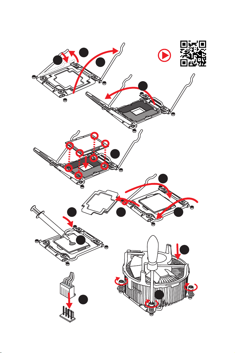
Installing a Processor/ Installation des Prozessors/ Installer un
processeur/ Установка процессора
1
3
2
https://youtu.be/ecdkLMmkya4
4
5
6
Quick Start
II
789
10
11
12
13
Page 3
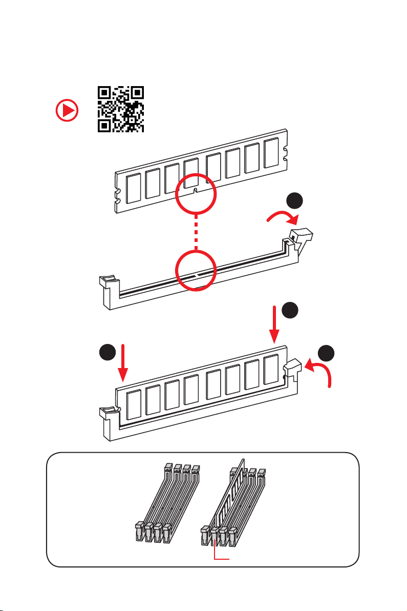
Installing DDR4 memory/ Installation des DDR4-Speichers/
Installer une mémoire DDR4/ Установка памяти DDR4
http://youtu.be/T03aDrJPyQs
1
2
2
DIMMC1
3
Quick Start
III
Page 4
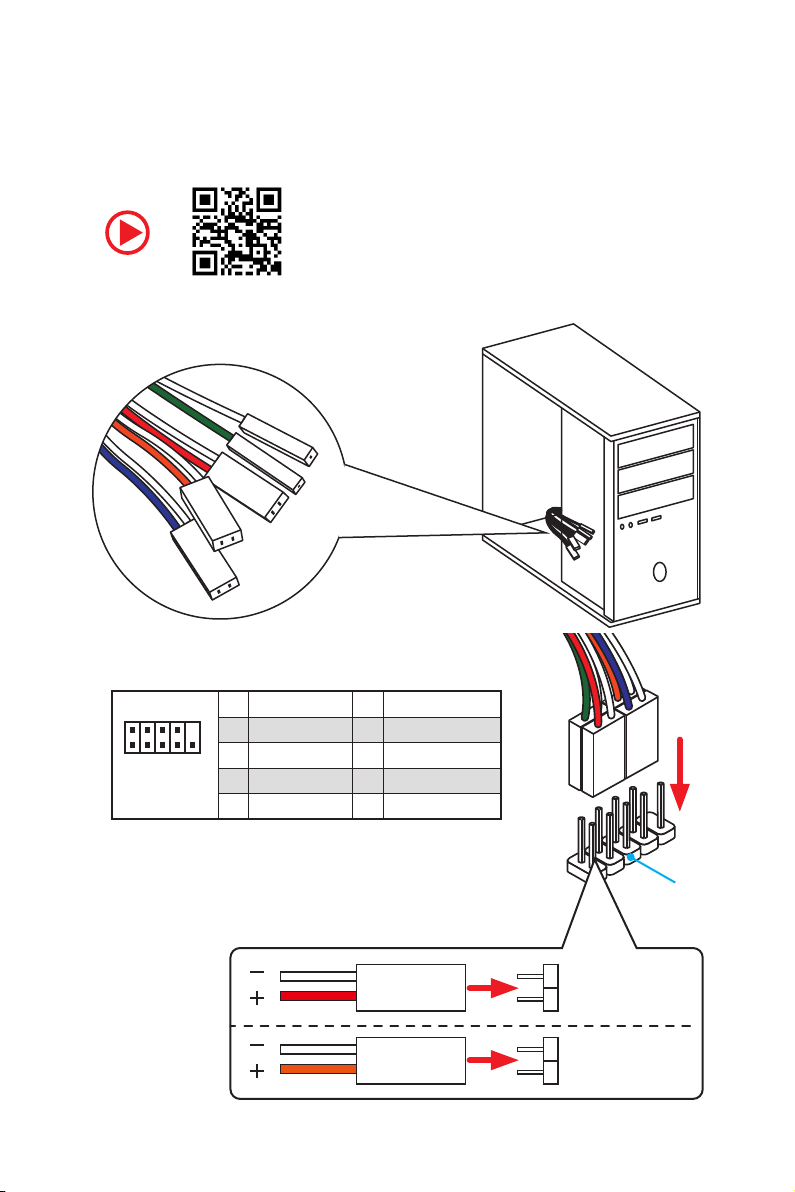
RESET SW
POWER SW
POWER LED+
POWER LED-
HDD LED
Connecting the Front Panel Header/ Anschließen der
Frontpanel-Stiftleiste/ Connecter un connecteur du panneau
avant/ Подключение разъемов передней панели
http://youtu.be/DPELIdVNZUI
IV
2 10
1
Quick Start
JFP1
1 HDD LED + 2 Power LED +
3 HDD LED - 4 Power LED -
5 Reset Switch 6 Power Switch
9
7 Reset Switch 8 Power Switch
9 Reserved 10 No Pin
HDD LED
POWER LED
RESET SW
HDD LED
JFP1
HDD LED HDD LED +
POWER LED POWER LED +
Page 5
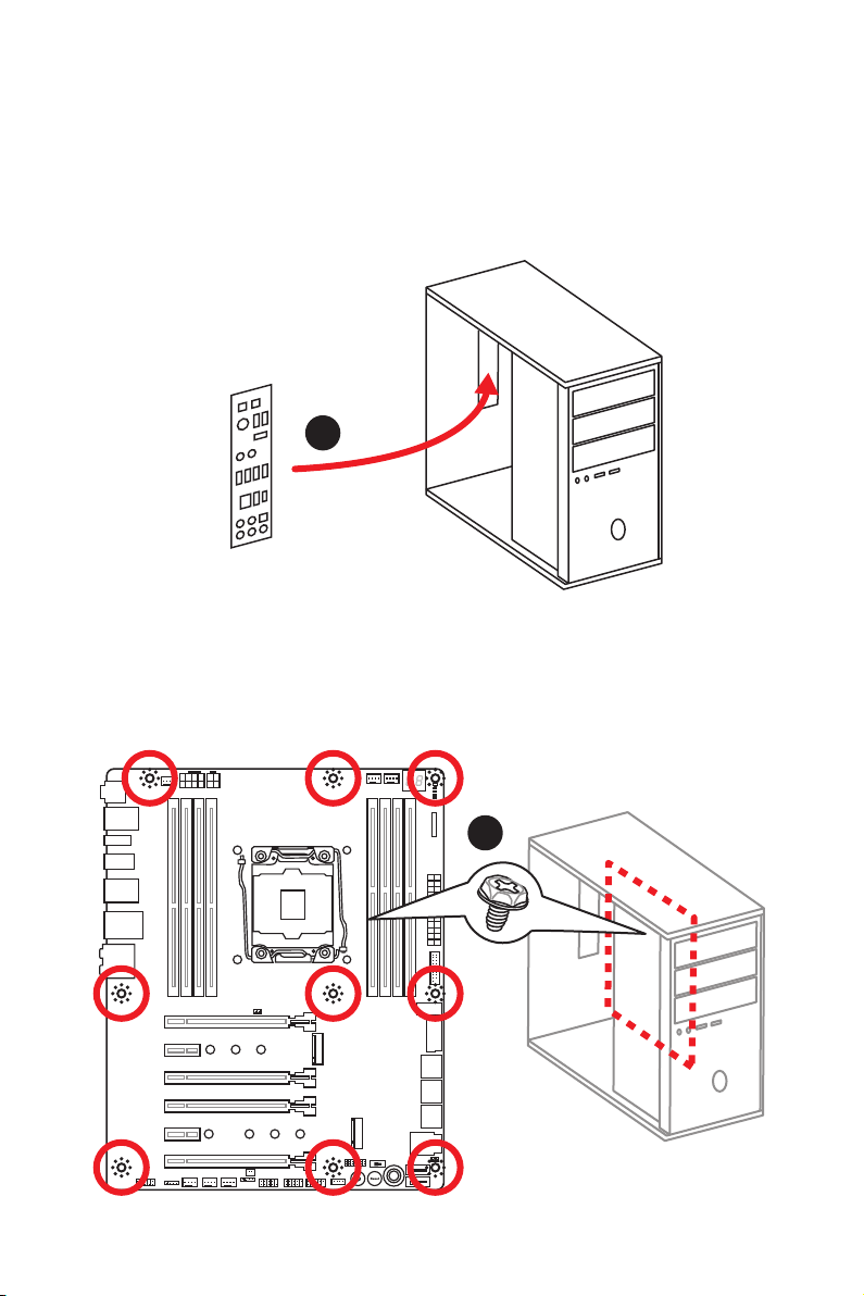
Installing the Motherboard/ Installation des Motherboards/
Installer la carte mère/ Установка материнской платы
1
2
Quick Start
V
Page 6
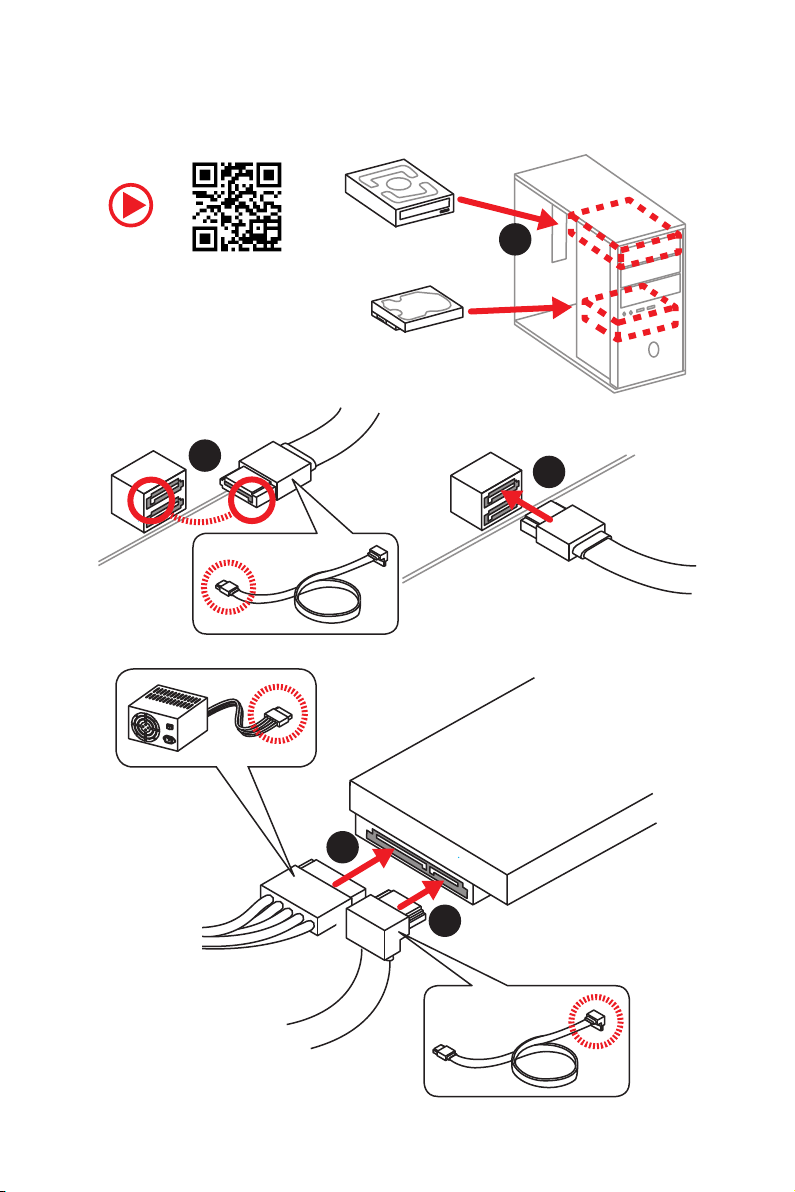
Installing SATA Drives/ Installation der SATA-Laufwerke/
Installer le disque dur SATA/ Установка дисков SATA
1
http://youtu.be/RZsMpqxythc
2
3
5
4
VI
Quick Start
Page 7
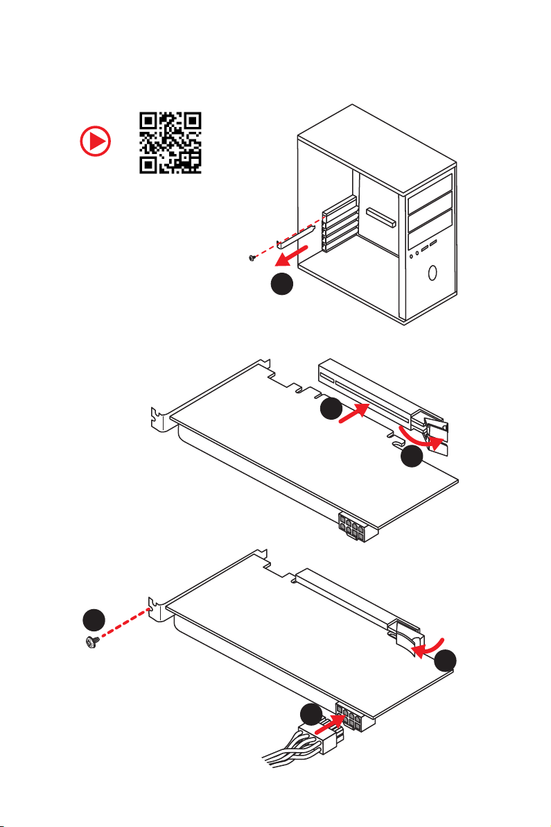
Installing a Graphics Card/ Einbau der Grafikkarte/ Installer
une carte graphique/ Установка дискретной видеокарты
http://youtu.be/mG0GZpr9w_A
1
3
2
5
4
6
Quick Start
VII
Page 8
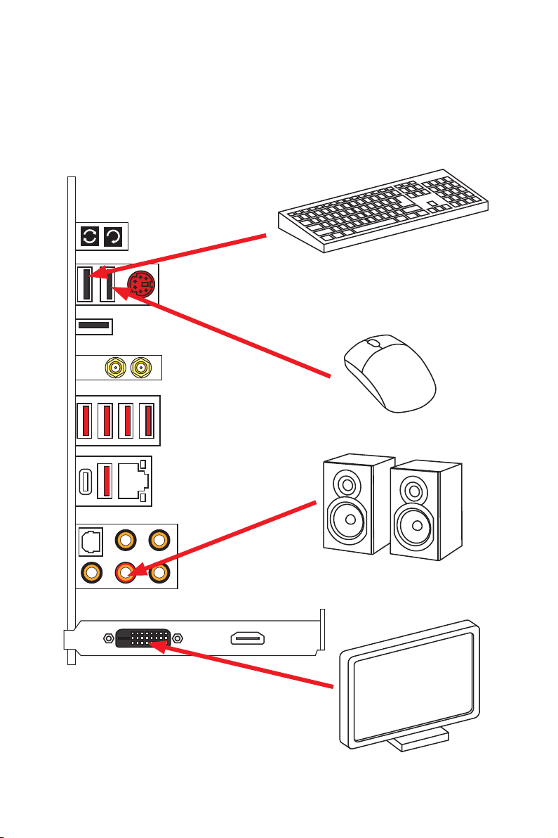
Connecting Peripheral Devices/ Peripheriegeräte/
Connecter un périphérique anschliessen/ Подключение
периферийных устройств
VIII
Quick Start
Page 9
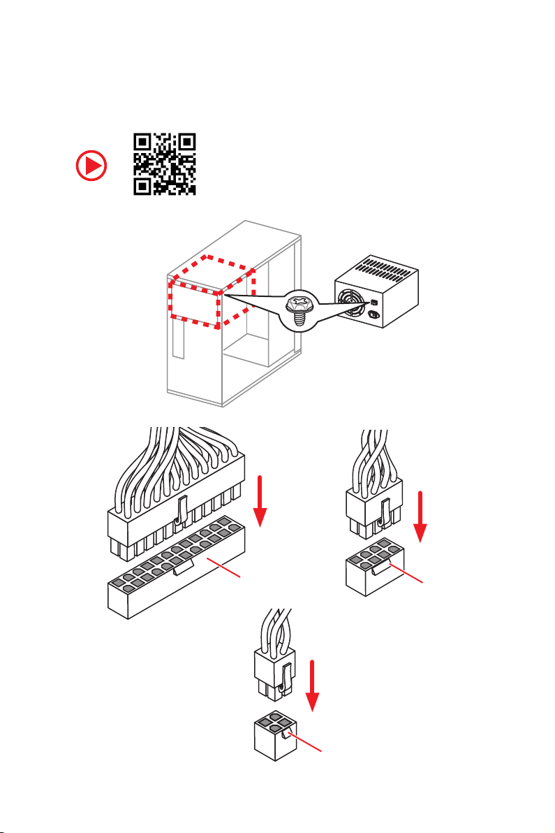
Connecting the Power Connectors/ Stromanschlüsse
anschliessen/ Connecter les câbles du module d’alimentation/
Подключение разъемов питания
http://youtu.be/gkDYyR_83I4
ATX_PWR1
CPU_PWR2
CPU_PWR1
Quick Start
IX
Page 10
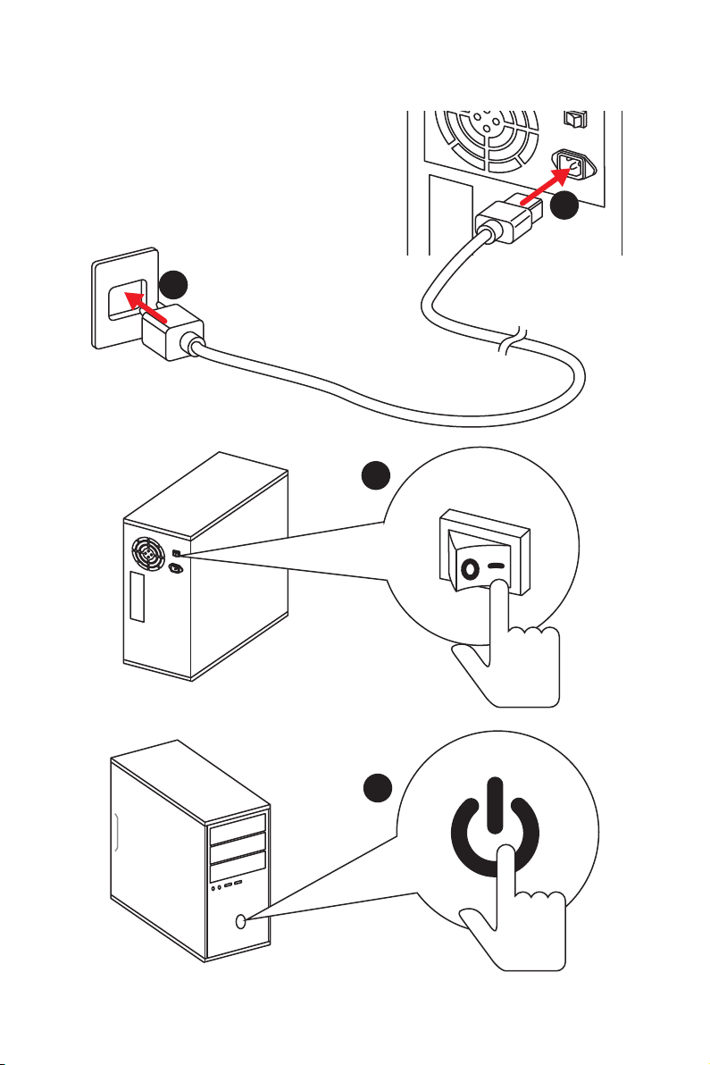
Power On/ Einschalten/ Mettre sous-tension/ Включение
питания
1
2
3
Quick Start
X
4
Page 11

Contents
Safety Information ................................................................................................. 3
Specifications ......................................................................................................... 4
Rear I/O Panel ..................................................................................................... 10
LAN Port LED Status Table................................................................................... 10
Audio Ports Configuration .................................................................................... 10
Realtek HD Audio Manager .................................................................................. 11
Installing Antennas ............................................................................................... 13
Overview of Components .................................................................................... 14
CPU Socket ........................................................................................................... 15
DIMM Slots ............................................................................................................ 16
PCI_E1~6: PCIe Expansion Slots .......................................................................... 19
PCIe slots bandwidth table ................................................................................... 19
U2_1: U.2 Connector ............................................................................................. 22
M2_1~2: M.2 Slots (Key M) ................................................................................... 23
SATA1~8: SATA 6Gb/s Connectors ....................................................................... 24
OC1: GAME BOOST Knob ..................................................................................... 26
JSLOW1: Slow Mode Booting Jumper .................................................................. 27
JAUD1: Front Audio Connector ............................................................................27
CPU_PWR1~2, ATX_PWR1: Power Connectors ................................................... 28
JFP1, JFP2: Front Panel Connectors ................................................................... 29
JUSB3, JUSB4: USB 3.1 Gen1 Connectors........................................................... 29
JUSB5: USB 3.1 Gen2 Type-C Connector ............................................................. 30
JUSB1~2: USB 2.0 Connectors ............................................................................. 31
JTPM1: TPM Module Connector ........................................................................... 31
CPU_FAN1, PUMP_FAN1, SYS_FAN1~4: Fan Connectors ................................... 32
VRAID1: Virtual RAID on CPU Connector ............................................................. 32
BIOS_SW1: Multi-BIOS Switch ............................................................................. 33
JBAT1: Clear CMOS (Reset BIOS) Jumper ........................................................... 34
POWER1, RESET1: Power Button, Reset Button ................................................. 34
JLED1: RGB LED connector ................................................................................. 35
JPWRLED1: LED light demonstration power input connector ............................ 35
V-Check Points ..................................................................................................... 36
Onboard LEDs ...................................................................................................... 36
EZ Debug LEDs ..................................................................................................... 36
DIMM LEDs ........................................................................................................... 36
Fan LEDs ............................................................................................................... 37
PCIe x16 slot LEDs................................................................................................ 37
XMP LED ............................................................................................................... 37
1
Page 12

Debug Code LED ................................................................................................... 38
Debug Code LED Table ......................................................................................... 38
ACPI States Codes ................................................................................................ 40
CPU Temperature ................................................................................................. 40
Updating LED Firmware ....................................................................................... 41
BIOS Setup ........................................................................................................... 42
Entering BIOS Setup ............................................................................................. 42
Resetting BIOS ...................................................................................................... 43
Updating BIOS ....................................................................................................... 43
EZ Mode ................................................................................................................ 45
Advanced Mode .................................................................................................... 47
OC Menu................................................................................................................ 48
Software Description ........................................................................................... 54
Installing Windows® 10 ......................................................................................... 54
Installing Drivers .................................................................................................. 54
Installing Utilities ................................................................................................. 54
2
Page 13

Safety Information
y The components included in this package are prone to damage from electrostatic
discharge (ESD). Please adhere to the following instructions to ensure successful
computer assembly.
y Ensure that all components are securely connected. Loose connections may cause
the computer to not recognize a component or fail to start.
y Hold the motherboard by the edges to avoid touching sensitive components.
y It is recommended to wear an electrostatic discharge (ESD) wrist strap when
handling the motherboard to prevent electrostatic damage. If an ESD wrist strap is
not available, discharge yourself of static electricity by touching another metal object
before handling the motherboard.
y Store the motherboard in an electrostatic shielding container or on an anti-static pad
whenever the motherboard is not installed.
y Before turning on the computer, ensure that there are no loose screws or metal
components on the motherboard or anywhere within the computer case.
y Do not boot the computer before installation is completed. This could cause
permanent damage to the components as well as injury to the user.
y If you need help during any installation step, please consult a certified computer
technician.
y Always turn off the power supply and unplug the power cord from the power outlet
before installing or removing any computer component.
y Keep this user guide for future reference.
y Keep this motherboard away from humidity.
y Make sure that your electrical outlet provides the same voltage as is indicated on the
PSU, before connecting the PSU to the electrical outlet.
y Place the power cord such a way that people can not step on it. Do not place anything
over the power cord.
y All cautions and warnings on the motherboard should be noted.
y If any of the following situations arises, get the motherboard checked by service
personnel:
Liquid has penetrated into the computer.
The motherboard has been exposed to moisture.
The motherboard does not work well or you can not get it work according to user
guide.
The motherboard has been dropped and damaged.
The motherboard has obvious sign of breakage.
y Do not leave this motherboard in an environment above 60°C (140°F), it may damage
the motherboard.
Safety Information
3
Page 14

Specifications
CPU
Supports Intel
LGA2066 Socket
®
Core™ X-Series Processor Family for
Chipset Intel
y 8x DDR4 memory slots, support up to 128GB*
y Quad channel memory architecture with the CPU that
supports up to 4-channels DDR4**
y Dual channel memory architecture with the CPU that
Memory
supports up to 2-channels DDR4**
y Supports Intel
* For the latest information about memory, please visit http://www.msi.com
** Please refer the DIMM Slots section for more details.
y 4x PCIe 3.0 x16 slots
Expansion Slots
y 2x PCIe 3.0 x1 slots
* Please refer to page 19 for PCIe 3.0 bandwidth table.
®
X299 Chipset
X-series processor support DDR4 4133(OC)/ 4000(OC)/
3866(OC)/ 3800(OC)/ 3733(OC)/ 3600(OC)/ 3466(OC)/
3400(OC)/ 3333(OC)/ 3200(OC)/ 3000(OC)/ 2933(OC)/
2800(OC)/ 2667/ 2400/ 2133 MHz*
X-series processor support DDR4 4500(OC)/ 4400(OC)/
4333(OC)/ 4266(OC)/ 4200(OC)/ 4133(OC)/ 4000(OC)/
3866(OC)/ 3800(OC)/ 3733(OC)/ 3600(OC)/ 3466(OC)/
3400(OC)/ 3333(OC)/ 3200(OC)/ 3000(OC)/ 2933(OC)/
2800(OC)/ 2667/ 2400/ 2133 MHz*
®
Extreme Memory Profile (XMP)
Support x16/x4/x16/x8 mode with the 44-lane CPU.*
Support x16/x4/x8/x0, x8/x4/x8/x8 modes with the 28-
lane CPU.*
Support x8/x0/x8/x0, x8/x4/x4/x0 modes with the 16-
lane CPU.*
Multi-GPU
LAN 1x Killer
Wirsless LAN &
Bluetooth
Specifications
4
®
y Supports up to 3-Way AMD
y Supports up to 3-Way NVIDIA
™
E2500 Gigabit LAN controller
®
CrossFire™ Technology
®
SLI™ Technology
y Killer™ Wireless-AC 1535 module
The Wireless module is pre-installed in the M2_3
(Key-E) slot.
Supports Wi-Fi 802.11 a/b/g/n/ac, dual band (2.4GHz,
5GHz) up to 867 Mbps speed.
Supports Bluetooth
®
4.1
Continued on next page
Page 15

Audio
USB
Storage
Continued from previous page
®
y Dual Realtek
ALC1220 Codec
y 7.1-Channel High Definition Audio
y Supports S/PDIF output
®
y ASMedia
ASM3142 Chipset
1x USB 3.1 Gen2 (SuperSpeed USB 10Gbps) Type-A port
on the back panel
2x USB 3.1 Gen2 (Super Speed USB 10Gbps) Type-C
ports (1 port on the back panel, 1 port available through
the internal USB connector)
y ASMedia
®
ASM1074 Chipset
3x USB 3.1 Gen1 (SuperSpeed USB) Type-A ports on the
back panel
®
y Intel
X299 Chipset
5x USB 3.1 Gen1 (SuperSpeed USB) ports (1 port on the
back panel, 4 ports available through the internal USB
connectors)
7x USB 2.0 (High-speed USB) ports (3 ports on the
back panel, 4 ports available through the internal USB
connectors)
®
Intel
X299 Chipset
y 8x SATA 6Gb/s ports*
y 2x M.2 slots (Key M)*
Supports up to PCIe 3.0 x4 and SATA 6Gb/s
M2_1 slot supports 2242/ 2260 /2280 storage devices
M2_2 slot supports 2242/ 2260 /2280/ 22110 storage
devices
®
Intel
Optane™ Memory Ready for all M.2 slots **
y 1x U.2 port *
Supports PCIe 3.0 x4 NVMe storage
y Supports Intel
* M.2 slots, U.2 port and SATA ports share the same bandwidth. Please refer to
page 24 for U.2, M.2 & SATA combination table.
** Please refer to the Intel
website.
***The functions will be supported depend on the CPU.
®
Smart Response Technology***
®
Optane™ Memory Configuration Guide on MSI
Continued on next page
Specifications
5
Page 16

RAID
Internal Connectors
Continued from previous page
®
X299 Chipset
Intel
y Supports RAID 0, RAID 1, RAID 5 and RAID 10 for SATA
storage devices
y Supports RAID 0 and RAID 1 for M.2 storage devices*
* M.2 PCIe RAID volume can be created with M.2/Optane Genie.
y 1x 24-pin ATX main power connector
y 1x 8-pin ATX 12V power connector
y 1x 4-pin ATX 12V power connector
y 8x SATA 6Gb/s connectors
y 3x M.2 slots (Key-M x2, Key-E x1)
y 1x U.2 port
y 2x USB 2.0 connectors (supports additional 4 USB 2.0
ports)
y 2x USB 3.1 Gen1 connectors (supports additional 4 USB 3.1
Gen1 ports)
y 1x USB 3.1 Gen2 Type-C port
y 1x 4-pin CPU fan connector
y 1x 4-pin Water Pump connector
y 4x 4-pin system fan connectors
y 1x Front panel audio connector
y 2x Front panel connectors
y 1x TPM module connector
y 1x Virtual RAID on CPU connector
y 1x Clear CMOS jumper
y 1x Slow mode booting jumper
y 1x Low temperature booting jumper
y 1x GAME BOOST knob
y 1x Power button
y 1x Reset button
y 1x Multi-BIOS switch
y 1x RGB LED connector
y 1x 2-Digit Debug Code LED
Specifications
6
Continued on next page
Page 17

Continued from previous page
y 1x Clear CMOS button
y 1x BIOS FLASHBACK+ button
y 1x PS/2 keyboard/ mouse combo port
y 3x USB 2.0 Type-A ports
Back Panel
Connectors
I/O Controller NUVOTON NCT6795 Controller Chip
Hardware Monitor
y 2x WiFi antenna connectors
y 4x USB 3.1 Gen1 Type-A ports
y 1x LAN (RJ45) port
y 1x USB 3.1 Gen2 Type-A port
y 1x USB 3.1 Gen2 Type-C port
y 1x Optical S/PDIF OUT connector
y 5x OFC audio jacks
y CPU/System temperature detection
y CPU/System fan speed detection
y CPU/System fan speed control
Form Factor
BIOS Features
y ATX Form Factor
y 12 in. x 9.6 in. (30.5 cm x 24.3 cm)
y 2x 128 Mb flash
y UEFI AMI BIOS
y ACPI 6.0, PnP 1.0a, SM BIOS 3.0
y Multi-language
Continued on next page
Specifications
7
Page 18

Software
Continued from previous page
y Drivers
y APP MANAGER
y SUPER CHARGER
y COMMAND CENTER
y LIVE UPDATE 6
y MSI SMART TOOL
y DRAGON EYE
y GAMING APP
y X-BOOST
y MYSTIC LIGHT
y RAMDISK
y FAST BOOT
y Killer Network Manager
y Nahimic Audio
y XSplit Gamecaster V2
y Tridef VR & Smart Cam
y SteelSeries Engine 3
y WTFast*
y CPU-Z MSI GAMING
®
y Intel
Extreme Tuning Utility
y Google Chrome
y Norton
* This offer is valid for a limited period only, for more information please visit
www.msi.com
™
,Google Toolbar, Google Drive
™
Internet Security Solution
MSI Special
Features
Specifications
8
y Audio Boost 4 Pro
y Nahimic 2
y Killer DoubleShot
y GAMING LAN with Killer LAN Manager
y Killer WiFi
y Turbo U.2
y Twin Turbo M.2
y Pump Fan
y Smart Fan Control
Continued on next page
Page 19

MSI Special
Features
Continued from previous page
y Mystic Light
y Mystic Light Extension
y Mystic light SYNC
y EZ DEBUG LED
y DDR4 Steel Armor
y M.2 SHIELD FROZR
y PCI-E Steel Armor
y U.2 Steel Armor
y VR Cover
y Muitl GPU - SLI Technology
y Muitl GPU - CrossFire Technology
y DDR4 Boost
y GAME Boost
y OC Engine
y USB with Type A+C
y Lightning USB
y Front Lightning USB
y Military Class 5
y 7000+ Quality Test
y VR Boost
y VR Ready
y GAMING HOTKEY
y GAMING MOUSE Control
y Click BIOS 5
y BIOS FLASHBACK+
y Dual BIOS
y Quadro SLI Ready
y Quadro Ready
y GAMING Certified
y SteelSeries Certified
Specifications
9
Page 20
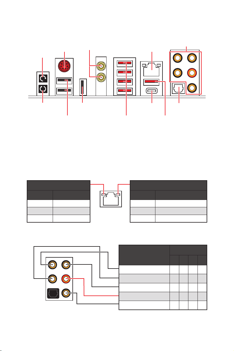
Rear I/O Panel
Clear CMOS
PS/2
WiFi Antenna
Connectors
LAN
Audio Ports
button
BIOS FLASHBACK+
button
USB 2.0/
BIOS FLASHBACK+
USB 2.0
USB 3.1 Gen2
Type-C
USB 3.1 Gen1
Type-A
Optical
S/PDIF-Out
USB 3.1 Gen2
Type-A
y Clear CMOS button - Power off your computer. Press and hold the Clear CMOS
button for about 5-10 seconds to reset BIOS to default values.
y BIOS FLASHBACK+ port/ button - Please refer to page 44 for Updating BIOS with
BIOS FLASHBACK+.
LAN Port LED Status Table
Link/ Activity LED
Status Description
Off No link
Yellow Linked
Blinking Data activity
Speed LED
Status Description
Off 10 Mbps connection
Green 100 Mbps connection
Orange 1 Gbps connection
Audio Ports Configuration
Rear I/O Panel
10
Audio Ports
Channel
2 4 6 8
Center/ Subwoofer Out ● ●
Rear Speaker Out ● ● ●
Line-In/ Side Speaker Out ●
Line-Out/ Front Speaker Out ● ● ● ●
Mic In
(●: connected, Blank: empty)
Page 21
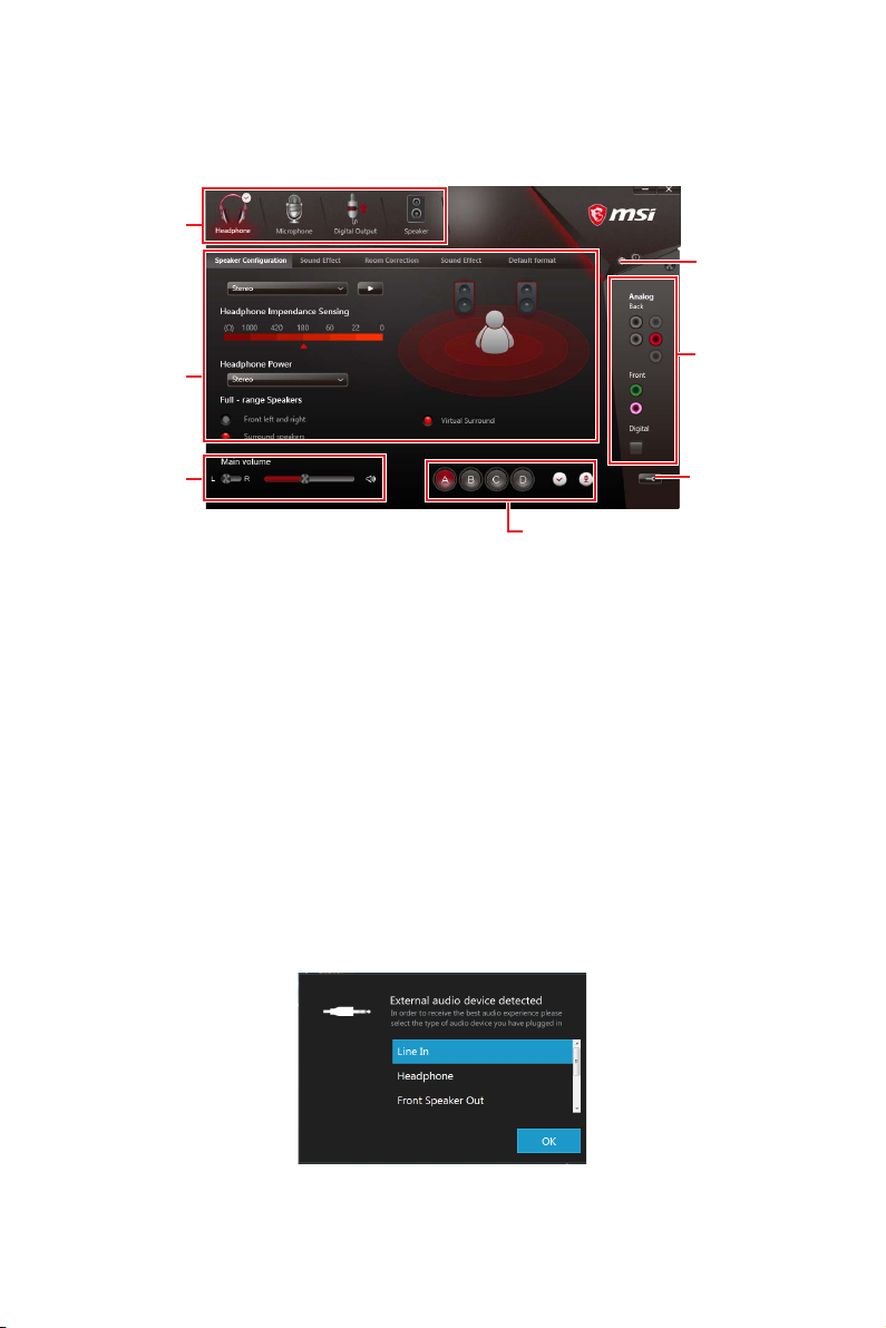
Realtek HD Audio Manager
After installing the Realtek HD Audio driver, the Realtek HD Audio Manager icon will
appear in the system tray. Double click on the icon to launch.
Device
Selection
Advanced
Settings
Application
Enhancement
Main Volume
Profiles
Jack Status
Connector
Strings
y Device Selection - allows you to select a audio output source to change the related
options. The check sign indicates the devices as default.
y Application Enhancement - the array of options will provide you a complete guidance
of anticipated sound effect for both output and input device.
y Main Volume - controls the volume or balance the right/left side of the speakers that
you plugged in front or rear panel by adjust the bar.
y Profiles - toggles between profiles.
y Advanced Settings - provides the mechanism to deal with 2 independent audio
streams.
y Jack Status - depicts all render and capture devices currently connected with your
computer.
y Connector Settings - configures the connection settings.
Auto popup dialog
When you plug into a device at an audio jack, a dialogue window will pop up asking you
which device is current connected.
Each jack corresponds to its default setting as shown on the next page.
Rear I/O Panel
11
Page 22
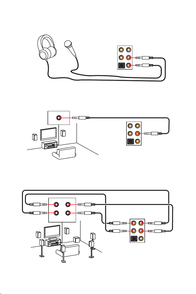
Audio jacks to headphone and microphone diagram
Audio jacks to stereo speakers diagram
AUDIO INPUT
Audio jacks to 7.1-channel speakers diagram
AUDIO INPUT
Rear Front
Side Center/
Subwoofer
Rear I/O Panel
12
Page 23
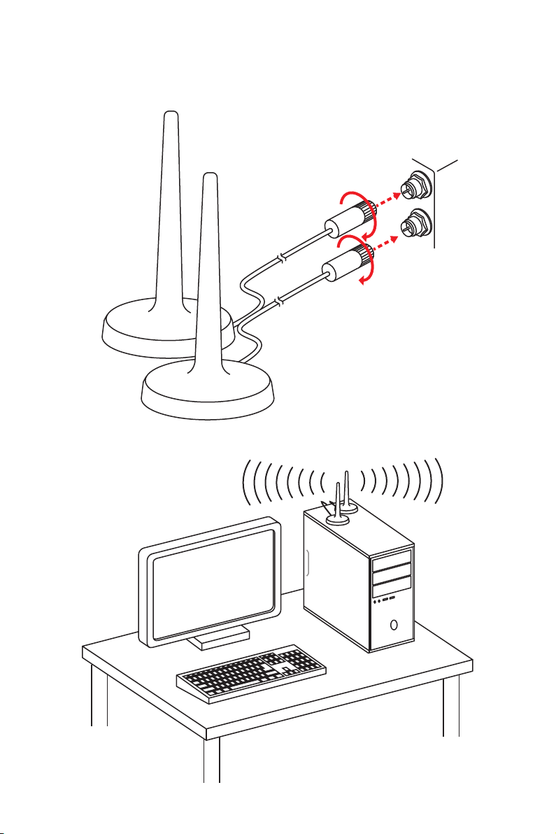
Installing Antennas
1. Screw the antennas tight to the WiFi antenna connectors as shown.
2. Place the antennas as high as possible.
Rear I/O Panel
13
Page 24
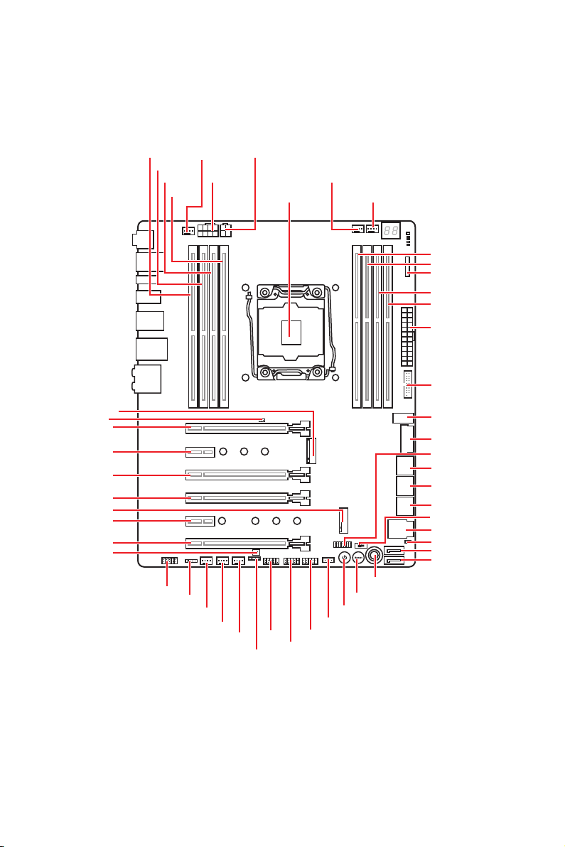
Overview of Components
M2_1
JBAT1
PCI_E1
PCI_E2
PCI_E3
PCI_E4
M2_2
PCI_E5
PCI_E6
JPWRLED1
DIMMB1
DIMMB2
DIMMA1
JAUD1
CPU_FAN1
DIMMA2
JLED1
SYSFAN4
CPU_PWR1
SYSFAN3
SYSFAN2
CPU_PWR2
JFP1
JFP2
CPU Socket
JUSB1
JUSB2
PUMP_FAN1
POWER1
VRAID1
SYS_FAN1
OC1
RESET1
DIMMC2
DIMMC1
V-Check Points
DIMMD2
DIMMD1
ATX_PWR1
JUSB4
JUSB5
JUSB3
JTPM1
SATA▼1▲2
SATA▼3▲4
SATA▼5▲6
BIOS_SW1
U2_1
JSLOW1
SATA7
SATA8
Overview of Components
14
Page 25
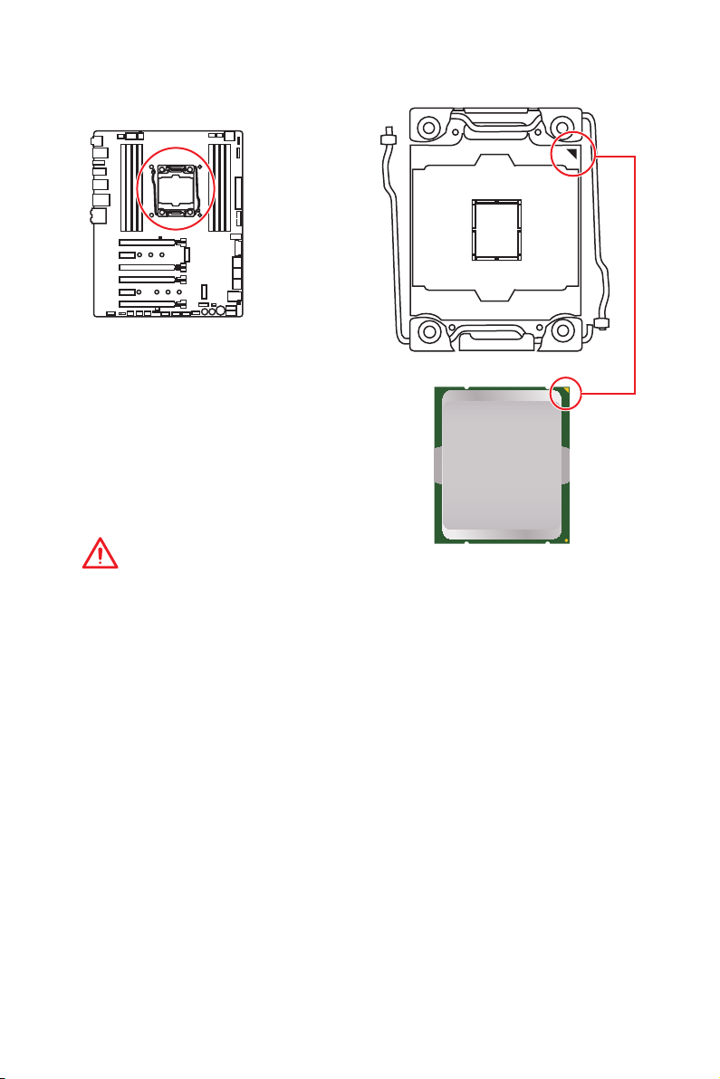
CPU Socket
Introduction to the LGA 2066 CPU
The surface of the LGA2066 CPU has
four alignment keys and a yellow triangle
to assist in correctly lining up the CPU
for motherboard placement. The yellow
triangle is the Pin 1 indicator.
Important
y
Always unplug the power cord from the power outlet before installing or removing
the CPU.
y
Please retain the CPU protective cap after installing the processor. MSI will deal with
Return Merchandise Authorization (RMA) requests if only the motherboard comes with
the protective cap on the CPU socket.
y
When installing a CPU, always remember to install a CPU heatsink. A CPU heatsink
is necessary to prevent overheating and maintain system stability.
y
Confirm that the CPU heatsink has formed a tight seal with the CPU before booting
your system.
y
Overheating can seriously damage the CPU and motherboard. Always make sure
the cooling fans work properly to protect the CPU from overheating. Be sure to apply
an even layer of thermal paste (or thermal tape) between the CPU and the heatsink to
enhance heat dissipation.
y
Whenever the CPU is not installed, always protect the CPU socket pins by covering
the socket with the plastic cap.
y
If you purchased a separate CPU and heatsink/ cooler, Please refer to the
documentation in the heatsink/ cooler package for more details about installation.
y
This motherboard is designed to support overclocking. Before attempting to
overclock, please make sure that all other system components can tolerate
overclocking. Any attempt to operate beyond product specifications is not
recommended. MSI
operation beyond product specifications.
®
does not guarantee the damages or risks caused by inadequate
Overview of Components
15
Page 26
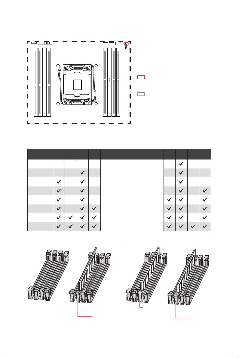
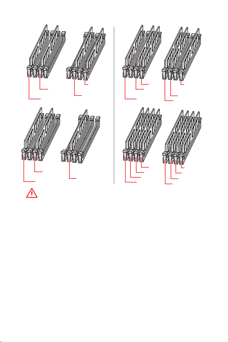
DIMM Slots
S/K LED : S/K LED indicates that
the installed CPU supports either
4-channels or 2-channels memory
architecture.
Red = 8 DIMMs support
(4-channels architecture CPU)
White = 4 DIMMs support
(2-channels architecture CPU)
B1B2A1A2 C2C1D2D1
Memory module installation recommendation (4-Channels architecture CPU )
B1 B2 A1 A2 Intel Core X-series CPU C2 C1 D2 D1
1 DIMM
2 DIMMs
3 DIMMs
4 DIMMs
5 DIMMs
6 DIMMs
7 DIMMs
8 DIMMs
Supports 4-channels
memory architecture
Overview of Components
16
DIMMC1
DIMMA1
DIMMC1
Page 27
DIMMA1
DIMMB1
DIMMD1
DIMMC1
DIMMA1
DIMMB1
DIMMA2
DIMMD1
DIMMC1
DIMMC2
DIMMA1
DIMMB1
DIMMC1
DIMMA2
DIMMA1
DIMMB2
DIMMB1
DIMMD1
DIMMD2
DIMMC1
DIMMC2
Important
y
Always insert a memory module in the DIMMC1 slot first.
y
To ensure system stability for Dual/ Triple/ Quad channel mode, memory modules
must be of the same type, number and density. And for every channel, the odd number
DIMM slot must to be installed first.
y
Due to chipset resource usage, the available capacity of memory will be a little less
than the amount of installed.
y
Based on Intel CPU specification, the Memory DIMM voltage below 1.35V is
suggested to protect the CPU.
y
Please note that the maximum capacity of addressable memory is 4GB or less
for 32-bit Windows OS due to the memory address limitation. Therefore, we
recommended that you to install 64-bit Windows OS if you want to install more than
4GB memory on the motherboard.
y
Some memory may operate at a lower frequency than the marked value when
overclocking due to the memory frequency operates dependent on its Serial Presence
Detect (SPD).
y
It is recommended to use a more efficient memory cooling system for full DIMMs
installation or overclocking.
y
The stability and compatibility of installed memory modules depend on installed CPU
and devices when overclocking.
Overview of Components
17
Page 28
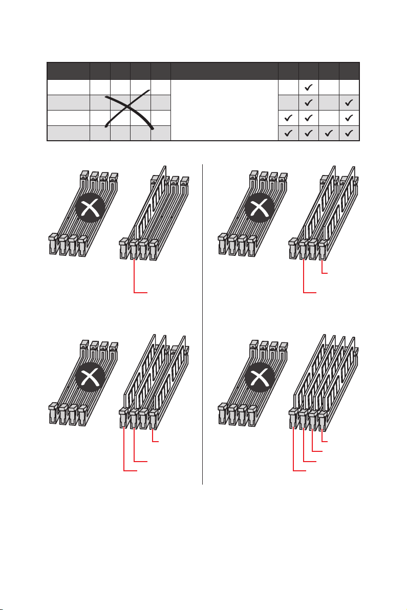
Memory module installation recommendation (2-Channels architecture CPU )
B1 B2 A1 A2 Intel Core X-series CPU C2 C1 D2 D1
1 DIMM
2 DIMMs
3 DIMMs
4 DIMMs
DIMMB1, B2, A1 and A2 are un-available
DIMMC1 DIMMC1
Supports 2-channels
memory architecture
DIMMD1
Overview of Components
18
DIMMD1 DIMMD1
DIMMD2
DIMMC1 DIMMC1
DIMMC2 DIMMC2
Page 29
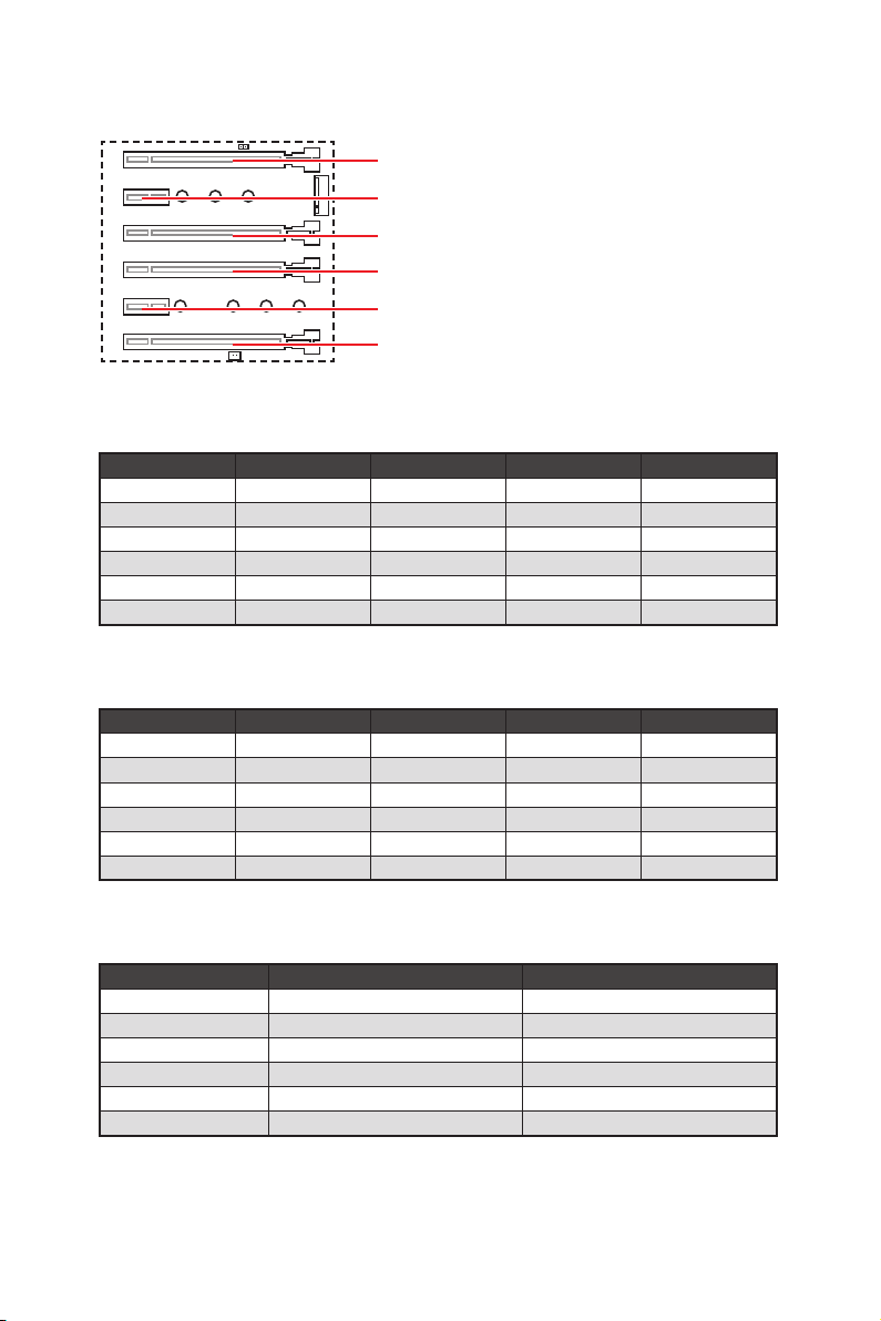
PCI_E1~6: PCIe Expansion Slots
PCI_E1: PCIe 3.0 x16 (CPU lanes)
PCI_E2: PCIe 3.0 x1 (PCH lanes)
PCI_E3: PCIe 3.0 x4 (CPU lanes)
PCI_E4: PCIe 3.0 x16 (CPU lanes)
PCI_E5: PCIe 3.0 x1 (PCH lanes)
PCI_E6: PCIe 3.0 x8 (CPU lanes)
PCIe slots bandwidth table
for 44-lane CPU
Graphics Card Single 2-Way* 2-Way 3-Way
PCI_E1 @ 3.0 x16 @ 3.0 x16 @ 3.0 x16 @ 3.0 x16
PCI_E2 3.0 x1 3.0 x1 3.0 x1 3.0 x1
PCI_E3 3.0 x4 3.0 x4 3.0 x4 3.0 x4
PCI_E4 3.0 x16 @ 3.0 x16 3.0 x16 @ 3.0 x16
PCI_E5 3.0 x1 3.0 x1 3.0 x1 3.0 x1
PCI_E6 3.0 x8 3.0 x8 @ 3.0 x8 @ 3.0 x8
(@: graphics card slot, *: best combination)
for 28-lane CPU
Graphics Card Single 2-Way* 2-Way 3-Way
PCI_E1 @ 3.0 x16 @ 3.0 x16 @ 3.0 x8 @ 3.0 x8
PCI_E2 3.0 x1 3.0 x1 3.0 x1 3.0 x1
PCI_E3 3.0 x4 3.0 x4 3.0 x4 3.0 x4
PCI_E4 3.0 x8 @ 3.0 x8 3.0 x8 @ 3.0 x8
PCI_E5 3.0 x1 3.0 x1 3.0 x1 3.0 x1
PCI_E6 Empty Empty @ 3.0 x8 @ 3.0 x8
(@: graphics card slot, *: best combination)
for 16-lane CPU
Graphics Card Single 2-Way*
PCI_E1 @ 3.0 x8 @ 3.0 x8
PCI_E2 3.0 x1 3.0 x1
PCI_E3 3.0 x4 Empty
PCI_E4 3.0 x4 @ 3.0 x8
PCI_E5 3.0 x1 3.0 x1
PCI_E6 ─ ─
(@: graphics card slot, ─: unavailable)
Overview of Components
19
Page 30
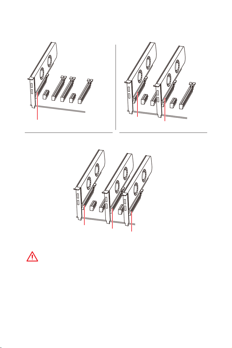
Multiple graphics cards installation recommendation
PCI_E1
For 44- & 28-lane CPU
PCI_E1
PCI_E4
PCI_E1
PCI_E4
PCI_E6
Important
y
If you install a large and heavy graphics card, you need to use a tool such as
MSI Gaming Series Graphics Card Bolster to support its weight and to prevent
deformation of the slot.
y
For a single PCIe x16 expansion card installation with optimum performance, using
the PCI_E1 slot is recommended.
Overview of Components
20
Page 31

Installing SLI graphics cards
For power supply recommendations for SLI configurations, please refer to the user
guide of your graphics card to make sure you meet all the system requirements.
To install SLI graphics cards:
1. Turn off your computer and disconnect the power cord, install two graphics cards
into the PCI_E1 and PCI_E4 slots.
2. Connect the two cards together using the SLI Bridge Connector.
3. Connect all PCIe power connectors of the graphics cards.
4. Reconnect the power cord, power up the computer and install the drivers and
software included in your graphics card package.
5. Right-click the Windows desktop and select NVIDIA Control Panel from the menu,
click on Configure SLI, Surround, PhysX in the left task pane and select Maximize
3D performance in the SLI configuration menu, and then click Apply.
Overview of Components
21
Page 32

U2_1: U.2 Connector
This connector is a U.2 interface port. Each connector can connect to one PCIe 3.0 x4
NVMe storage device.
Video Demonstration
Watch the video to learn how to Install
U.2 SSD.
Installing U.2 SSD
1. Connect the U.2 cable to the U.2 connector on the
motherboard.
2. Connect the U.2 cable to the U.2 SSD.
3. Connect the U.2 cable to power adapter cable.
http://youtu.be/KgFvKDxymvw
U.2 SSD
U.2 Connector
U.2 Cable
2
1
Connect to power
adapter cable
* M.2 slots, U.2 port and SATA ports share the same bandwidth. Please refer to page
24 for U.2, M.2 & SATA combination table.
Overview of Components
22
3
Page 33

M2_1~2: M.2 Slots (Key M)
y
Intel® RST only supports PCIe M.2 SSD with UEFI ROM.
y
Intel® Optane™ Memory Ready for all M.2 slots.
Using M.2 SHIELD FROZR
This motherboard has M.2 SHIELD
FROZR on the M.2 slots for heat
dissipation from the M.2 modules.
Before installing the M.2 module
for the first time, you need to
remove two screws, lift the M.2
SHIELD FROZR and remove the
protective films
from the thermal
pads.
Important
Installing M.2 module
1. Remove the screw from the base
screw.
2. Remove the base screw.
3. Tighten the base screw into
the hole of the distance to the
M.2 slot as the length your M.2
module.
4. Insert your M.2 module into the
M.2 slot at a 30-degree angle.
5. Put the screw in the notch on the
trailing edge of your M.2 module and
tighten it into the base screw.
Video Demonstration
Watch the video to learn how to Install M.2 module.
http://youtu.be/JCTFABytrYA
4
3
1
30°
2
5
Overview of Components
23
Page 34

SATA1~8: SATA 6Gb/s Connectors
These connectors are SATA 6Gb/s interface ports. Each connector can connect to one
SATA device.
SATA2
SATA1
SATA4
SATA3
SATA6
SATA5
SATA7
SATA8
Important
y
Please do not fold the SATA cable at a 90-degree angle. Data loss may result during
transmission otherwise.
y
SATA cables have identical plugs on either sides of the cable. However, it is
recommended that the flat connector be connected to the motherboard for space
saving purposes.
U.2, M.2 & SATA combination table
Slot Available connectors
M2_1 PCIe SATA SATA PCIe PCIe SATA SATA PCIe
M2_2 PCIe SATA PCIe SATA PCIe SATA PCIe SATA
SATA1 ✓ ─ ─ ✓ ✓ ─ ─ ✓
SATA2 ✓ ─ ✓ ─ ✓ ─ ✓ ─
SATA3 ✓ ✓ ✓ ✓ ✓ ✓ ✓ ✓
SATA4 ✓ ✓ ✓ ✓ ✓ ✓ ✓ ✓
U2_1 ✓ ✓ ✓ ✓ Empty Empty Empty Empty
SATA5 ─ ─ ─ ─ ✓ ✓ ✓ ✓
SATA6 ─ ─ ─ ─ ✓ ✓ ✓ ✓
SATA7 ─ ─ ─ ─ ✓ ✓ ✓ ✓
SATA8 ─ ─ ─ ─ ✓ ✓ ✓ ✓
(SATA: M.2 SATA SSD, PCIe: M.2 PCIe SSD, ✓: available, ─: unavailable)
Overview of Components
24
Page 35

M.2 slots with examples of various combination possibilities
1xU.2+ 2xM.2 PCIe+ 4xSATA
SATA1SATA3
SATA4 SATA2U.2
M.2 PCIe
M.2 PCIe
1xU.2+ 1xM.2 PCIe+ 1xM.2 SATA+
3xSATA
SATA1SATA3
SATA4U.2
M.2 PCIe
M.2 SATA
1xU.2+ 1xM.2 SATA+ 1xM.2 PCIe+
3xSATA
SATA4 SATA2U.2
M.2 SATA
M.2 PCIe
2xM.2 PCIe+ 8xSATA
SATA4SATA6 SATA2
M.2 PCIe
M.2 PCIe
SATA7
SATA8
SATA3
SATA1SATA3SATA5
1xM.2 SATA+ 1xM.2 PCIe+ 7xSATA
SATA4SATA6 SATA2
SATA3SATA5
M.2 SATA
M.2 PCIe
SATA7
SATA8
1xM.2 PCIe+ 1xM.2 SATA+ 7xSATA
SATA4SATA6
M.2 PCIe
M.2 SATA
Overview of Components
SATA7
SATA8
SATA1SATA3SATA5
25
Page 36

OC1: GAME BOOST Knob
This knob allows you to manually select a stage from number 0 (default) to number 11
(extreme) for overclocking the processor. The processor’s voltage and frequency will
be automatically adjusted after you power on your computer.
GAME BOOST knob
0
1
1
1
0
1
Using GAME BOOST Knob
To setup the GAME BOOST knob, take the following steps:
1. Set the GAME BOOST knob to hardware mode in BIOS Setup.
Note: The light of this knob will be turned on to indicate that the GAME BOOST is
controller by hardware. When the light is off, it indicates that the GAME BOOST is
controller by BIOS.
2. Power off the computer.
3. Rotate the GAME BOOST knob to select the overclocking stage as you desire.
Stage
4. Power on and then GAME BOOST will automatically overclock processor depending
on the stage you selected.
To disable GAME BOOST:
1. Set the GAME BOOST knob to HW mode in BIOS Setup.
2. Power off the computer.
3. Rotate the GAME BOOST knob to 0 and then power on. The configuration
parameters will be returned to default values.
i5-7640X i7-7740X i7-7800X i7-7820X i9-7900X
0 4.0 GHz 4.3 GHz 3.5 GHz 3.6 GHz 3.3 GHz
1 4.5 GHz 4.8 GHz 4.1 GHz 4.4 GHz 4.4 GHz
2 4.6 GHz 4.9 GHz 4.2 GHz 4.5 GHz 4.5 GHz
4 4.7 GHz 5.0 GHz 4.3 GHz 4.6 GHz 4.6 GHz
6 4.8 GHz 5 .1 GHz 4.4 GHz 4.7 GHz 4.7 GHz
8 4.9 GHz 5.2 GHz 4.5 GHz 4.8 GHz 4.8 GHz
10 5.0 GHz 5.3 GHz 4.6 GHz 4.9 GHz 4.9 GHz
11 5 .1 GHz 5.4 GHz 4.7 GHz 5.0 GHz 5.0 GHz
CPU Frequency
Important
y
When using GAME BOOST with Core-X series processor, it is recommended to use
liquid CPU cooler with dual fan radiator for better cooling and performance.
2
4
8
6
Overview of Components
26
Page 37

y
You can also control the GAME BOOST function in BIOS Setup or with MSI COMMAND
CENTER software.
y
In order to optimize performance and improve system stability, when you activate the
GAME BOOST function, please leave the settings in the BIOS > OC menu unchanged.
y
The success of overclocking depends on the components of your computer.
y
We do not guarantee the GAME BOOST overclocking range or the damages/ risks
caused by overclocking behavior.
y
MSI components are recommended for better compatibility when using GAME
BOOST function.
JSLOW1: Slow Mode Booting Jumper
This jumper is used for LN2 cooling solution, that provides the extreme overclocking
conditions, to boot at a stable processor frequency and to prevent the system from
crashing.
Normal
(default)
Enabled
(Please enable this
jumper during BIOS
POST.)
Red LED indicates that the
Slow Mode is enabled.
Important
y
Users will try extreme low temperature overclocking at their own risks. The
overclocking results will vary according to the CPU version.
y
Please don’t switch to Enabled when power-off or the system will be un-bootable.
JAUD1: Front Audio Connector
This connector allows you to connect audio jacks on the front panel.
2 10
1
1 MIC L 2 Ground
3 MIC R 4 NC
5 Head Phone R 6 MIC Detection
7 SENSE_SEND 8 No Pin
9 Head Phone L 10 Head Phone Detection
9
Overview of Components
27
Page 38

CPU_PWR1~2, ATX_PWR1: Power Connectors
These connectors allow you to connect an ATX power supply.
4
2 1
5
3
CPU)_PWR1
CPU_PWR2
8
4 1
1 Ground 5 +12V
2 Ground 6 +12V
3 Ground 7 +12V
4 Ground 8 +12V
1 Ground 3 +12V
2 Ground 4 +12V
1 +3.3V 13 +3.3V
2 +3.3V 14 -12V
3 Ground 15 Ground
24
12
JPWR1
131
4 +5V 16 PS-ON#
5 Ground 17 Ground
6 +5V 18 Ground
7 Ground 19 Ground
8 PWR OK 20 Res
9 5VSB 21 +5V
10 +12V 22 +5V
11 +12V 23 +5V
12 +3.3V 24 Ground
Important
Make sure that all the power cables are securely connected to a proper ATX power
supply to ensure stable operation of the motherboard.
Overview of Components
28
Page 39

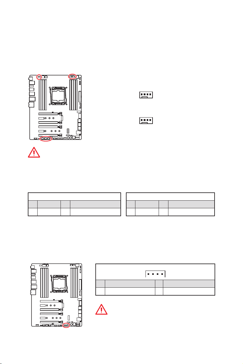
JFP1, JFP2: Front Panel Connectors
These connectors connect to the switches and LEDs on the front panel.
2 10
JFP1
1
9
1 HDD LED + 2 Power LED +
3 HDD LED - 4 Power LED -
5 Reset Switch 6 Power Switch
7 Reset Switch 8 Power Switch
9 Reserved 10 No Pin
1
JFP2
1 Speaker - 2 Buzzer +
3 Buzzer - 4 Speaker +
JUSB3, JUSB4: USB 3.1 Gen1 Connectors
These connectors allow you to connect USB 3.1 Gen1 ports on the front panel.
10 11
1
20
1 Power 11 USB2.0+
2 USB3_RX_DN 12 USB2.0-
3 USB3_RX_DP 13 Ground
4 Ground 14 USB3_TX_C_DP
5 USB3_TX_C_DN 15 USB3_TX_C_DN
6 USB3_TX_C_DP 16 Ground
7 Ground 17 USB3_RX_DP
8 USB2.0- 18 USB3_RX_DN
9 USB2.0+ 19 Power
10 Ground 20 No Pin
Important
Note that the Power and Ground pins must be connected correctly to avoid possible
damage.
Overview of Components
29
Page 40

Charger Port
The JUSB4 connector is a charger port which can increase USB power output for fast
charging your smartphone or USB-powered devices. The Charger Port is hardware
controlled by motherboard chip, it can still charge your device in suspend, hibernate
state or even shutdown states. However, when you boot the computer into Windows
you will need to install the MSI
Charging mode.
®
SUPER CHARGER application to turn ON/OFF the
®
Video Demonstration
Watch the video to learn how to charge the smartphone with SuperCharger. http://youtu.be/FCyvjr5NbOw
Important
When the Charging mode is enabled, the Charger Port data syncing will be disabled.
JUSB5: USB 3.1 Gen2 Type-C Connector
This connector allows you to connect USB 3.1 Gen2 Type-C connector on the front
panel. The connector possesses a foolproof design. When you connect the cable, be
sure to connect it with the corresponding orientation.
,
Overview of Components
30
USB Type-C port on
the front panel
USB Type-C Cable
JUSB5
Page 41

JUSB1~2: USB 2.0 Connectors
These connectors allow you to connect USB 2.0 ports on the front panel.
2 10
1
1 VCC 2 VCC
3 USB0- 4 USB1-
5 USB0+ 6 USB1+
7 Ground 8 Ground
9 No Pin 10 NC
9
Important
y
Note that the VCC and Ground pins must be connected correctly to avoid possible
damage.
y
In order to recharge your iPad,iPhone and iPod through USB ports, please install
®
MSI
SUPER CHARGER utility.
JTPM1: TPM Module Connector
This connector is for TPM (Trusted Platform Module). Please refer to the TPM security
platform manual for more details and usages.
2 14
1
1 LPC Clock 2 3V Standby power
3 LPC Reset 4 3.3V Power
5 LPC address & data pin0 6 Serial IRQ
7 LPC address & data pin1 8 5V Power
9 LPC address & data pin2 10 No Pin
11 LPC address & data pin3 12 Ground
13 LPC Frame 14 Ground
13
Overview of Components
31
Page 42
CPU_FAN1, PUMP_FAN1, SYS_FAN1~4: Fan Connectors
Fan connectors can be classified as PWM (Pulse Width Modulation) Mode or DC Mode.
PWM Mode fan connectors provide constant 12V output and adjust fan speed with
speed control signal. DC Mode fan connectors control fan speed by changing voltage.
When you plug a 3-pin (Non-PWM) fan to a fan connector in PWM mode, the fan speed
will always maintain at 100%, which might create a lot of noise. You can follow the
instruction below to adjust the fan connector to PWM or DC Mode.
Auto-detection Mode fan connectors
1
CPU_FAN1/ PUMP _FAN1
1
SYS_FAN1~4
Important
y
You can switch between PWM mode and DC mode and adjust fan speed in BIOS >
HARDWARE MONITOR.
y
Make sure fans are working properly after switching the PWM/ DC mode.
Pin definition of fan connectors
PWM Mode pin definition
1 Ground 2 +12V
3 Sense 4 Speed Control Signal
1 Ground 2 Voltage Control
3 Sense 4 NC
DC Mode pin definition
VRAID1: Virtual RAID on CPU Connector
This connector allows you to connect the VROC (Virtual RAID on CPU) key module. You
need to enable the VROC function with Intel
enterprise) driver.
1 GND 2 VCC3
3 GND 4 SATA_RAID_KEY
The VROC key module is purchased separately.
Overview of Components
32
®
RSTe (Intel® Rapid Storage Technology
1
Important
Page 43

BIOS_SW1: Multi-BIOS Switch
This motherboard has two built-in BIOS ROMs (Labeled A and B, default BIOS ROM is
A). If one is crashed, you can shift to the other for booting by sliding the switch.
BIOS A LED BIOS B LED
(default)
BIOS BBIOS A
Recovering BIOS
When BIOS updating fails or causes the computer non-bootable, you can recover the
failed BIOS by the steps below. Before recovering, please download the latest BIOS
file that matches your motherboard model from MSI website. And then save the BIOS
file to the root of the USB flash drive.
1. Power off the computer.
2. Switch to the normal BIOS ROM with Multi-BIOS switch.
3. Insert the USB flash drive into the computer.
4. Power on the computer and press Del key to enter BIOS setup during POST.
5. Select the M-FLASH tab and click on Yes to reboot the system and enter the flash
mode.
6. Select a BIOS file to perform the BIOS recovering process.
7. Switch to the failed BIOS ROM with Multi-BIOS switch, and click on Yes to start
recovering BIOS.
8. After the recovering process is completed, the system will reboot automatically
Important
y
Do not use the Multi-BIOS switch when system is booting up.
y
You can also use the LIVE UPDATE or BIOS FLASHBACK+ utility to flash BIOS. Please
refer to BIOS section for details.
Overview of Components
33
Page 44

JBAT1: Clear CMOS (Reset BIOS) Jumper
There is CMOS memory onboard that is external powered from a battery located on
the motherboard to save system configuration data. If you want to clear the system
configuration, set the jumper to clear the CMOS memory.
Keep Data
(default)
Clear CMOS/
Reset BIOS
Resetting BIOS to default values
1. Power off the computer and unplug the power cord
2. Use a jumper cap to short JBAT1 for about 5-10 seconds.
3. Remove the jumper cap from JBAT1.
4. Plug the power cord and power on the computer.
POWER1, RESET1: Power Button, Reset Button
The Power / Reset button allows you to power on / reset the computer.
Reset
Power button
Reset button
Overview of Components
34
Page 45

JLED1: RGB LED connector
These connectors allow you to connect the 5050 RGB LED strips.
1
1 +12V 2 G
3 R 4 B
1
Extension cable
JLED1
5050 LED strip
Video Demonstration
Watch the video to learn how to install 5050 RGB LED strips to RGB LED
connector.
https://youtu.be/CqNHyADzd2Q
Important
y
This connector supports 5050 RGB multi-color LED strips (12V/G/R/B) with the
maximum power rating of 3A (12V). Please keeping the LED strip shorter than 2
meters to prevent dimming.
y
Always turn off the power supply and unplug the power cord from the power outlet
before installing or removing the RGB LED strip.
y
Please use MSI’s software to control the extended LED strip.
JPWRLED1: LED light demonstration power input connector
This connector is used by retailers to demonstrate onboard LED lights.
JPWRLED1 - LED power input
Overview of Components
35
Page 46
V-Check Points
These voltage checkpoints are used to measure the current system voltages. A
multimeter (not included) will be required to check voltages. To measure voltage,
place test leads on the GND (screw mounting hole) and a V-Check Point. Please refer
to the manual of your multimeter for more information.
GND (Screw mounting hole)
6
RING
CPU
DDR
SA
IO
1
CORE
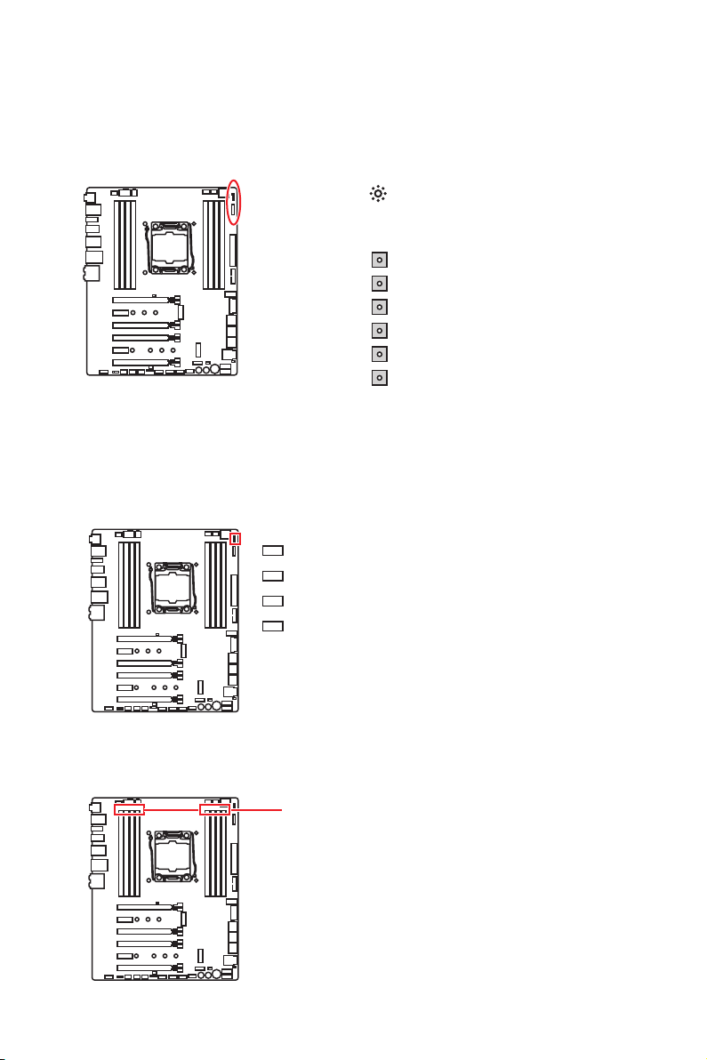
Onboard LEDs
EZ Debug LEDs
These LEDs indicate the status of key components during booting process. When an
error is occurred, the corresponding LED stays lit until the problem is solved.
CPU - indicates CPU is not detected or fail.
DRAM - indicates DRAM is not detected or fail.
VGA - indicates GPU is not detected or fail.
BOOT - indicates the booting device is not detected
or fail.
DIMM LEDs
These LED indicate the memory modules are installed.
DIMM LEDs
Onboard LEDs
36
Page 47

Fan LEDs
These LEDs indicate the fan control mode.
PUMP_FAN1 LED
CPU_FAN1 LED
PCIe x16 slot LEDs
These LED indicate the PCIe x16 slots status.
PCI_E1 LED
PCI_E3 LED
PCI_E4 LED
PCI_E6 LED
LED Color Fan control mode
Red PWM mode
Green DC mode
LED Color PCIe slot status
Red x16 mode
White x8, x4, x1 mode
XMP LED
This LED indicates the XMP (Extreme Memory Profile) mode is enabled.
XMP LED
Onboard LEDs
37
Page 48

Debug Code LED
The Debug Code LED displays progress and error codes during and after POST. Refer
to the Debug Code LED table for details.
Hexadecimal Character Table
Hexadecimal 0 1 2 3 4 5 6 7 8 9 A B C D E F
Debug Code
LED display
0 1 2 3 4 5 6 7 8 9 A B C D E F
Boot Phases
Security (SEC) – initial low-level initialization
Pre-EFI Initialization (PEI) – memory initialization
Driver Execution Environment (DXE) – main hardware initialization
Boot Device Selection (BDS) – system setup, pre-OS user interface & selecting a
bootable device (CD/DVD, HDD, USB, Network, Shell, …)
Debug Code LED Table
SEC Progress Codes
Power on. Reset type detection (soft/
01
hard)
02 AP initialization before microcode loading
System Agent initialization before
03
microcode loading
PCH initialization before microcode
04
loading
06 Microcode loading
07 AP initialization after microcode loading
System Agent initialization after
08
microcode loading
09 PCH initialization after microcode loading
0B Cache initialization
SEC Error Codes
0C - 0D Reserved for future AMI SEC error codes
0E Microcode not found
0F Microcode not loaded
PEI Progress Codes
10 PEI Core is started
11 Pre-memory CPU initialization is started
Pre-memory CPU initialization (CPU
12 - 14
module specific)
Pre-memory System Agent initialization
15
is started
Pre-Memory System Agent initialization
16 - 18
(System Agent module specific)
19 Pre-memory PCH initialization is started
Pre-memory PCH initialization (PCH
1A - 1C
module specific)
Memory initialization. Serial Presence
2B
Detect (SPD) data reading
Onboard LEDs
38
Page 49

Memory initialization. Memory presence
2C
detection
Memory initialization. Programming
2D
memory timing information
Memory initialization. Configuring
2E
memory
2F Memory initialization (other)
31 Memory Installed
32 CPU post-memory initialization is started
CPU post-memory initialization. Cache
33
initialization
CPU post-memory initialization.
34
Application Processor(s) (AP)
initialization
CPU post-memory initialization. Boot
35
Strap Processor (BSP) selection
CPU post-memory initialization. System
36
Management Mode (SMM) initialization
Post-Memory System Agent initialization
37
is started
Post-Memory System Agent initialization
38 - 3A
(System Agent module specific)
3B Post-Memory PCH initialization is started
Post-Memory PCH initialization (PCH
3C - 3E
module specific)
4F DXE IPL is started
PEI Error Codes
Memory initialization error. Invalid
50
memory type or incompatible memory
speed
Memory initialization error. SPD reading
51
has failed
Memory initialization error. Invalid
52
memory size or memory modules do
not match
Memory initialization error. No usable
53
memory detected
54 Unspecified memory initialization error
55 Memory not installed
56 Invalid CPU type or Speed
57 CPU mismatch
CPU self test failed or possible CPU
58
cache error
CPU micro-code is not found or micro-
59
code update is failed
5A Internal CPU error
5B Reset PPI is not available
5C - 5F Reserved for future AMI error codes
DXE Progress Codes
60 DXE Core is started
61 NVRAM initialization
62 Installation of the PCH Runtime Services
63 CPU DXE initialization is started
CPU DXE initialization (CPU module
64 - 67
specific)
68 PCI host bridge initialization
69 System Agent DXE initialization is started
System Agent DXE SMM initialization is
6A
started
System Agent DXE initialization (System
6B - 6F
Agent module specific)
70 PCH DXE initialization is started
71 PCH DXE SMM initialization is started
72 PCH devices initialization
PCH DXE Initialization (PCH module
73 - 77
specific)
78 ACPI module initialization
79 CSM initialization
7A - 7F Reserved for future AMI DXE codes
Boot Device Selection (BDS) phase is
90
started
91 Driver connecting is started
92 PCI Bus initialization is started
93 PCI Bus Hot Plug Controller Initialization
94 PCI Bus Enumeration 32
95 PCI Bus Request Resources
96 PCI Bus Assign Resources
97 Console Output devices connect
98 Console input devices connect
99 Super IO Initialization
9A USB initialization is started
9B USB Reset
9C USB Detect
9D USB Enable
9E -9F Reserved for future AMI codes
A0 IDE initialization is started
A1 IDE Reset
A2 IDE Detect
A3 IDE Enable
A4 SCSI initialization is started
A5 SCSI Reset
A6 SCSI Detect
A7 SCSI Enable
Onboard LEDs
39
Page 50

A8 Setup Verifying Password
A9 Start of Setup
AB Setup Input Wait
AD Ready To Boot event
AE Legacy Boot event
AF Exit Boot Services event
B0 Runtime Set Virtual Address MAP Begin
B1 Runtime Set Virtual Address MAP End
B2 Legacy Option ROM Initialization
B3 System Reset
B4 USB hot plug
B5 PCI bus hot plug
B6 Clean-up of NVRAM
Configuration Reset (reset of NVRAM
B7
settings)
B8 - BF Reserved for future AMI codes
DXE Error Codes
D0 CPU initialization error
D1 System Agent initialization error
D2 PCH initialization error
Some of the Architectural Protocols are
D3
not available
PCI resource allocation error. Out of
D4
Resources
D5 No Space for Legacy Option ROM
D6 No Console Output Devices are found
D7 No Console Input Devices are found
D8 Invalid password
Error loading Boot Option (LoadImage
D9
returned error)
Boot Option is failed (StartImage
DA
returned error)
DB Flash update is failed
DC Reset protocol is not available
S3 Resume Progress Codes
S3 Resume is stared (S3 Resume PPI is
E0
called by the DXE IPL)
E1 S3 Boot Script execution
E2 Video repost
E3 OS S3 wake vector call
E4 - E7 Reserved for future AMI progress codes
S3 Resume Error Codes
E8 S3 Resume Failed
E9 S3 Resume PPI not Found
EA S3 Resume Boot Script Error
EB S3 OS Wake Error
EC - EF Reserved for future AMI error codes
Recovery Progress Codes
Recovery condition triggered by firmware
F0
(Auto recovery)
Recovery condition triggered by user
F1
(Forced recovery)
F2 Recovery process started
F3 Recovery firmware image is found
F4 Recovery firmware image is loaded
F5 - F7 Reserved for future AMI progress codes
Recovery Error Codes
F8 Recovery PPI is not available
F9 Recovery capsule is not found
FA Invalid recovery capsule
FB - FF Reserved for future AMI error codes
ACPI States Codes
The following codes appear after booting
and the operating system into ACPI
modes.
01 System is entering S1 sleep state
02 System is entering S2 sleep state
03 System is entering S3 sleep state
04 System is entering S4 sleep state
05 System is entering S5 sleep state
System is waking up from the S1 sleep
10
state
System is waking up from the S2 sleep
20
state
System is waking up from the S3 sleep
30
state
System is waking up from the S4 sleep
40
state
System has transitioned into ACPI mode.
AC
Interrupt controller is in PIC mode.
System has transitioned into ACPI mode.
AA
Interrupt controller is in APIC mode.
CPU Temperature
Displays current CPU temperature after
00 - 99
the system has fully booted into the OS.
Onboard LEDs
40
Page 51

Updating LED Firmware
Updating the LED firmware can help improve lighting effect.
To update LED firmware:
1. Install and launch MSI LIVE UPDATE 6.
2. Select BIOS Update.
3. Click on Scan button. If the LED firmware needs to be updated, the version of the
firmware will appear in the list.
4. Select the item in the list.
5. Click on Total installer button to download and install the firmware.
6. When the process is 100% completed, you need to restart your computer to enable
the LED firmware.
Onboard LEDs
41
Page 52

BIOS Setup
The default settings offer the optimal performance for system stability in normal
conditions. You should always keep the default settings to avoid possible system
damage or failure booting unless you are familiar with BIOS.
Important
y
BIOS items are continuously update for better system performance. Therefore, the
description may be slightly different from the latest BIOS and should be for reference
only. You could also refer to the HELP information panel for BIOS item description.
y
The pictures in this chapter are for reference only and may vary from the product you
purchased.
Entering BIOS Setup
Please refer the following methods to enter BIOS setup.
y Press Delete key, when the Press DEL key to enter Setup Menu, F11 to enter Boot
Menu message appears on the screen during the boot process.
y Use MSI FAST BOOT application. Click on GO2BIOS button and choose OK. The
system will reboot and enter BIOS setup directly.
Click on GO2BIOS
Function key
F1: General Help
F2: Add/ Remove a favorite item
F3: Enter Favorites menu
F4: Enter CPU Specifications menu
F5: Enter Memory-Z menu
F6: Load optimized defaults
F7: Switch between Advanced mode and EZ mode
F8: Load Overclocking Profile
F9: Save Overclocking Profile
F10: Save Change and Reset*
F12: Take a screenshot and save it to USB flash drive (FAT/ FAT32 format only).
Ctrl+F: Enter Search page
* When you press F10, a confirmation window appears and it provides the modification
information. Select between Yes or No to confirm your choice.
42
BIOS Setup
Page 53

Resetting BIOS
You might need to restore the default BIOS setting to solve certain problems. There are
several ways to reset BIOS:
y Go to BIOS and press F6 to load optimized defaults.
y Short the Clear CMOS jumper on the motherboard.
Important
Be sure the computer is off before clearing CMOS data. Please refer to the Clear
CMOS jumper section for resetting BIOS.
Updating BIOS
Updating BIOS with M-FLASH
Before updating:
Please download the latest BIOS file that matches your motherboard model from MSI
website. And then save the BIOS file into the USB flash drive.
Updating BIOS:
1. Press Del key to enter the BIOS Setup during POST.
2. Insert the USB flash drive that contains the update file into the computer.
3. Select the M-FLASH tab and click on Yes to reboot the system and enter the flash
mode.
4. Select a BIOS file to perform the BIOS update process.
5. After the flashing process is 100% completed, the system will reboot
automatically.
Updating the BIOS with Live Update 6
Before updating:
Make sure the LAN driver is already installed and the Internet connection is set
properly.
Updating BIOS:
1. Install and launch MSI LIVE UPDATE 6.
2. Select BIOS Update.
3. Click on Scan button.
4. Click on Download icon to download and install the latest BIOS file.
5. Click Next and choose In Windows mode. And then click Next and Start to start
updating BIOS.
6. After the flashing process is 100% completed, the system will restart
automatically.
BIOS Setup
43
Page 54

Updating BIOS with BIOS FLASHBACK+
Before updating:
Please download the latest BIOS file that matches your motherboard model from MSI
website and rename the BIOS file to MSI.ROM. And then, save the MSI.ROM file to the
root of USB flash drive.
Important
Only the FAT32 format USB flash drive supports updating BIOS by BIOS FLASHBACK+.
1. Connect power supply to CPU_PWR1 and ATX_PWR1. (No other components are
necessary but power supply.)
2. Plug the USB flash drive that contains the MSI.ROM file into the BIOS
FLASHBACK+ port on rear I/O panel.
3. Press the BIOS FLASHBACK+ button to flash BIOS, and the light of BIOS
FLASHBACK+ button starts flashing.
4. After the flashing BIOS process is 100% completed, the button light would stop
flashing and would be off simultaneously.
®
44
BIOS Setup
Page 55

EZ Mode
At EZ mode, it provides the basic system information and allows you to configure the
basic setting. To configure the advanced BIOS settings, please enter the Advanced
Mode by pressing the Setup Mode switch or F7 function key.
XMP switch
SearchScreenshotSetup Mode switch
Language
System
information
GAME BOOST
switch
Information
display
M-Flash
Favorites
Hardware
Monitor
Boot device
priority bar
Function
buttons
y GAME BOOST switch - click on the center button to switch GAME BOOST control
between software (SW) and hardware (HW) . The inner circle represents the current
stage of hardware GAME BOOST and the outer circle stands for software. You can read
the CPU frequency of each GAME BOOST stage by clicking on the
icon at right-
bottom corner.
Important
Please don’t make any changes in OC menu and don’t load defaults to keep the
optimal performance and system stability after activating the GAME BOOST function.
y XMP switch - click on the inner circle to enable/ disable the X.M.P. (Extreme Memory
Profile). Switch the outer circle to select the X.M.P. profile. This switch will only be
available if the X.M.P. supported memory module is installed.
y Setup Mode switch - press this tab or the F7 key to switch between Advanced mode
and EZ mode.
y Screenshot - click on this tab or the F12 key to take a screenshot and save it to USB
flash drive (FAT/ FAT32 format only).
y Search - click on this tab or the Ctrl+F keys and the search page will show. It allows
you to search by BIOS item name, enter the item name to find the item listing. Move
the mouse over a blank space and right click the mouse to exit search page.
Important
In search page, only the F6, F10 and F12 function keys are available.
y Language - allows you to select the language of BIOS setup.
y System information - shows the CPU/ DDR speed, CPU/ MB temperature, MB/ CPU
type, memory size, CPU/ DDR voltage, BIOS version and build date.
y Boot device priority bar - you can move the device icons to change the boot priority.
The boot priority from high to low is left to right.
BIOS Setup
45
Page 56

y Information display - click on the CPU, Memory, Storage, Fan Info and Help buttons
on left side to display related information.
y Function buttons - enable or disable the LAN Option ROM, M.2/Optane Genie, HD
audio controller, AHCI, RAID, CPU Fan Fail Warning Control and BIOS Log Review by
clicking on their respective button.
y M-Flash - click on this button to display the M-Flash menu that provides the way to
update BIOS with a USB flash drive.
y Hardware Monitor - click on this button to display the Hardware Monitor menu that
allows you to manually control the fan speed by percentage.
y Favorites - press the Favorites tab or the F3 key to enter Favorites menu. It allows
you to create personal BIOS menu where you can save and access favorite/ frequentlyused BIOS setting items.
Default HomePage - allows you to select a BIOS menu (e.g. SETTINGS, OC...,etc)
as the BIOS home page.
Favorite1~5 - allows you to add the frequently-used/ favorite BIOS setting items
in one page.
To add a BIOS item to a favorite page (Favorite 1~5)
1. Move the mouse over a BIOS item not only on BIOS menu but also on search
page.
2. Right-click or press F2 key.
3. Choose a favorite page and click on OK.
To delete a BIOS item from favorite page
1. Move the mouse over a BIOS item on favorite page (Favorite 1~5)
2. Right-click or press F2 key.
3. Choose Delete and click on OK.
46
BIOS Setup
Page 57

Advanced Mode
Press Setup Mode switch or F7 function key can switch between EZ Mode and
Advanced Mode in BIOS setup.
XMP switch
GAME BOOST
switch
SearchScreenshotSetup Mode switch
Language
System
information
Boot device
priority bar
BIOS menu
selection
Menu display
BIOS menu
selection
y GAME BOOST switch/ XMP switch/ Setup Mode switch/ Screenshot/ Favorites/
Language/ System information/ Boot device priority bar - please refer to the
descriptions of EZ Mode Overview section.
y BIOS menu selection - the following options are available:
SETTINGS - allows you to specify the parameters for chipset and boot devices.
OC - allows you to adjust the frequency and voltage. Increasing the frequency may
get better performance.
M-FLASH - provides the way to update BIOS with a USB flash drive.
OC PROFILE - allows you to manage overclocking profiles.
HARDWARE MONITOR - allows you to set the speeds of fans and monitor voltages
of system.
BOARD EXPLORER - provides the information of installed devices on this
motherboard.
y Menu display - provides BIOS setting items and information to be configured.
BIOS Setup
47
Page 58

OC Menu
This menu is for advanced users who want to overclock the motherboard.
Important
y
Overclocking your PC manually is only recommended for advanced users.
y
Overclocking is not guaranteed, and if done improperly, it could void your warranty or
severely damage your hardware.
y
If you are unfamiliar with overclocking, we advise you to use GAME BOOST function
for easy overclocking.
f OC Explore Mode [Normal]
Enables or disables to show the normal or expert version of OC settings.
[Normal] Provides the regular OC settings in BIOS setup.
[Expert] Provides the advanced OC settings for OC expert to configure in BIOS
Note: We use * as the symbol for the OC settings of Expert mode.
f CPU Ratio Apply Mode [All Core]*
Sets applied mode for CPU ratio. This item only appears when a CPU that supports
Turbo Boost is installed.
[All Core] Activate the CPU Ratio field. All CPU cores will run the same CPU ratio
[Per Core] Activate the X-Core Ratio Limit field. Sets each CPU core ratio
setup.
that be set in CPU Ratio.
separately in X-Core Ratio Limit.
f CPU Ratio [Auto]
Sets the CPU ratio that is used to determine CPU clock speed. This item can only be
changed if the processor supports this function.
f Adjusted CPU Frequency
Shows the adjusted CPU frequency. Read-only.
BIOS Setup
48
Page 59

f CPU Ratio Mode [Dynamic Mode]*
Selects the CPU Ratio operating mode. This item will appear when you set the CPU
ratio manually.
[Fixed Mode] Fixes the CPU ratio.
[Dynamic Mode] CPU ratio will be changed dynamically according to the CPU
loading.
f CPU Ratio Offset When Running AVX [Auto]
Sets a offset value to lower the CPU core ratio. It could be helpful for heat dissipation
when running AVX instruction set. If set to Auto, BIOS will configure this setting
automatically. This item appears when the installed CPU supports this function.
f Ring Ratio [Auto]
Sets the ring ratio. The valid value range depends on the installed CPU.
f Adjusted Ring Frequency
Shows the adjusted Ring frequency. Read-only.
f Misc Setting*
Press Enter, + or - key to open or close the following 3 items related to CPU features.
fEIST [Enabled]*
Enables or disables the Enhanced Intel
®
SpeedStep Technology.
[Enabled] Enables the EIST to adjust CPU voltage and core frequency
dynamically. It can decrease average power consumption and
average heat production.
[Disabled] Disables EIST.
fIntel Turbo Boost [Enabled]*
Enables or disables the Intel
®
Turbo Boost. This item appears when the installed
CPU supports this function.
[Enabled] Enables this function to boost CPU performance automatically above
rated specifications when system request the highest performance
state.
[Disabled] Disables this function.
fEnhanced Turbo [Auto]*
Enables or disables Enhanced Turbo function for all CPU cores to boost CPU
performance. This item appears when the installed CPU supports this function.
[Auto] This setting will be configured automatically by BIOS.
[Enabled] All CPU cores would be increased to maximum turbo ratio.
[Disabled] Disables this function.
f Extreme Memory Profile (X.M.P.) [Disabled]
X.M.P. (Extreme Memory Profile) is the overclocking technology by memory module.
Please enable XMP or select a profile of memory module for overclocking the memory.
This item will be available when the memory modules that support X.M.P. is installed.
f DRAM Reference Clock [Auto]*
Sets the DRAM reference clock. The valid value range depends on the installed CPU.
This item appears when a CPU that supports this adjustment is installed.
BIOS Setup
49
Page 60

f DRAM Frequency [Auto]
Sets the DRAM frequency. Please note the overclocking behavior is not guaranteed.
f Adjusted DRAM Frequency
Shows the adjusted DRAM frequency. Read-only.
f DRAM Timing Mode [Link]
Selects the memory timing mode.
[Link] Allows user to configure the DRAM timing for all memory channel.
[UnLink] Allows user to configure the DRAM timing for respective memory
f Advanced DRAM Configuration
Press Enter to enter the sub-menu. User can set the memory timing for each/ all
memory channel. The system may become un-stable or un-bootable after changing
memory timing. If it occurs, please clear the CMOS data and restore the default
settings. (Refer to the Clear CMOS jumper/ button section to clear the CMOS data, and
enter the BIOS to load the default settings.)
f Memory Fast Boot [Auto]*
Enables or disables the initiation and training for memory every booting.
[Auto] The setting will be configured automatically by BIOS.
[Enabled] System will completely keep the archives of first intiation and training
[Disabled] The memory will be initialed and trained every booting.
f DigitALL Power
Press Enter to enter the sub-menu. Controls the digital powers related to CPU PWM.
f VCCIN Voltage [Auto]
Sets the CPU input voltage. The CPU input voltage is the CPU power source that is
shared with components of the CPU.
channel.
for memory. So the memory will not be initialed and trained when
booting to accelerate the system booting time.
f CPU Voltages control [Auto]
These options allows you to set the voltages related to CPU. If set to Auto, BIOS will
set these voltages automatically or you can set it manually.
f DRAM Voltages control [Auto]
These options allows you to set the voltages related to memory. If set to Auto, BIOS
will set these voltages automatically or you can set it manually.
f PCH Voltages control [Auto] (optional)
These options allows you to set the voltages related to PCH. If set to Auto, BIOS will
set these voltages automatically or you can set it manually.
f CPU Memory Changed Detect [Enabled]*
Enables or disables the system to issue a warning message during boot when the CPU
or memory has been replaced.
[Enabled] The system will issue a warning message during boot and than needs to
[Disabled] Disables this function and keeps the current BIOS settings.
BIOS Setup
50
load the default settings for new devices.
Page 61

f CPU Specifications
Press Enter to enter the sub-menu. This sub-menu displays the information of
installed CPU. You can also access this information menu at any time by pressing [F4].
Read only.
fCPU Technology Support
Press Enter to enter the sub-menu. The sub-menu shows the key features of
installed CPU. Read only.
f MEMORY-Z
Press Enter to enter the sub-menu. This sub-menu displays all the settings and
timings of installed memory. You can also access this information menu at any time by
pressing [F5].
fDIMMx Memory SPD
Press Enter to enter the sub-menu. The sub-menu displays the information of
installed memory. Read only.
f CPU Features
Press Enter to enter the sub-menu.
fHyper-Threading [Enabled]
Intel Hyper-Threading technology treats the multi cores inside the processor as
multi logical processors that can execute instructions simultaneously. In this way,
the system performance is highly improved. This item appears when the installed
CPU supports this technology.
[Enable] Enables Intel Hyper-Threading technology.
[Disabled] Disables this item if the system does not support HT function.
fLimit CPUID Maximum [Disabled]
Enables or disables the extended CPUID value.
[Enabled] BIOS limits the maximum CPUID input value to circumvent boot
[Disabled] Use the actual maximum CPUID input value.
fIntel Virtualization Tech [Enabled]
Enables or disables Intel Virtualization technology.
[Enabled] Enables Intel Virtualization technology and allows a platform to run
[Disabled] Disables this function.
problems with older operating system that do not support the
processor with extended CPUID value.
multiple operating systems in independent partitions. The system
can function as multiple systems virtually.
fIntel VT-D Tech [Disabled]
Enables or disables Intel VT-D (Intel Virtualization for Directed I/O) technology.
fHardware Prefetcher [Enabled]
Enables or disables the hardware prefetcher (MLC Streamer prefetcher).
[Enabled] Allows the hardware prefetcher to automatically pre-fetch data
and instructions into L2 cache from memory for tuning the CPU
performance.
[Disabled] Disables the hardware prefetcher.
BIOS Setup
51
Page 62

fAdjacent Cache Line Prefetch [Enabled]
Enables or disables the CPU hardware prefetcher (MLC Spatial prefetcher).
[Enabled] Enables adjacent cache line prefetching for reducing the cache
[Disabled] Enables the requested cache line only.
fCPU AES Instructions [Enabled]
Enables or disables the CPU AES (Advanced Encryption Standard-New
Instructions) support. This item appears when a CPU supports this function.
fIntel Adaptive Thermal Monitor [Enabled]
Enables or disables the Intel adaptive thermal monitor function to protect the CPU
from overheating.
[Enabled] Throttles down the CPU core clock speed when the CPU is over the
[Disabled] Disables this function.
fIntel C-State [Auto]
Enables or disables the Intel C-state. C-state is a processor power management
technology defined by ACPI.
[Auto] This setting will be configured automatically by BIOS.
[Enabled] Detects the idle state of system and reduce CPU power consumption
[Disabled] Disable this function.
fC1E Support [Disabled]
Enables or disables the C1E function for power-saving in halt state. This item
appears when Intel C-State is enabled.
[Enabled] Enables C1E function to reduce the CPU frequency and voltage for
[Disabled] Disables this function.
fPackage C State Limit [Auto]
This item allows you to select a CPU C-state level for power-saving when system is
idle. The options of C-state depend on the installed CPU. This item appears when
Intel C-State is enabled.
fCFG Lock [Enabled]
Lock or un-lock the MSR 0xE2[15], CFG lock bit.
[Enabled] Locks the CFG lock bit.
[Disabled] Un-locks the CFG lock bit.
fLong Duration Power Limit (W) [Auto]
Sets the long duration TDP power limit for CPU in Turbo Boost mode.
fLong Duration Maintained (s) [Auto]
Sets the maintaining time for Long duration power Limit(W).
latency time and tuning the performance to the specific application.
adaptive temperature.
accordingly.
power-saving in halt state.
52
BIOS Setup
Page 63

fShort Duration Power Limit (W) [Auto]
Sets the short duration TDP power limit for CPU in Turbo Boost mode.
fCPU Current Limit (A) [Auto]
Sets maximum current limit of CPU package in Turbo Boost mode. When the
current is over the specified value, the CPU will automatically reduce the core
frequency for reducing the current.
fInternal VR OVP OCP Protection [Auto]
Enables or disables the over-voltage protection and over-current protection for
CPU internal VR (Voltage Regulator).
[Auto] This setting will be configured automatically by BIOS.
[Enabled] Enables the limitation of internal VR for over-voltage protection and
[Disabled] Disables this function for overclocking.
fInternal VR Efficiency Management [Auto]
Enables or disables the CPU internal VR efficiency management.
[Auto] This setting will be configured automatically by BIOS.
[Enabled] Enables the VR effciency management for power-saving control.
[Disabled] Disables this function.
over-current protection.
BIOS Setup
53
Page 64

Software Description
Installing Windows® 10
1. Power on the computer.
2. Insert the Windows® 10 disc into your optical drive.
3. Press the Restart button on the computer case.
4. Press F11 key during the computer POST (Power-On Self Test) to get into Boot
Menu.
5. Select your optical drive from the Boot Menu.
6. Press any key when screen shows Press any key to boot from CD or DVD...
message.
7. Follow the instructions on the screen to install Windows
Installing Drivers
1. Start up your computer in Windows® 10.
®
2. Insert MSI
3. The installer will automatically appear and it will find and list all necessary
drivers.
4. Click Install button.
5. The software installation will then be in progress, after it has finished it will
prompt you to restart.
6. Click OK button to finish.
7. Restart your computer.
Driver Disc into your optical drive.
Installing Utilities
Before you install utilities, you must complete drivers installation.
1. Insert MSI
2. The installer will automatically appear.
3. Click Utilities tab.
4. Select the utilities you want to install.
5. Click Install button.
6. The utilities installation will then be in progress, after it has finished it will prompt
you to restart.
7. Click OK button to finish.
8. Restart your computer.
®
Driver Disc into your optical drive.
®
10.
Software Description
54
Page 65

Inhalt
Sicherheitshinweis ................................................................................................ 3
Spezifikationen ...................................................................................................... 4
Rückseite E/A ...................................................................................................... 11
LAN Port LED Zustandstabelle ............................................................................ 11
Konfiguration der Audioanschlüsse ..................................................................... 11
Realtek HD Audio Manager .................................................................................. 12
Antennen installieren ........................................................................................... 14
Übersicht der Komponenten ............................................................................... 15
CPU Sockel ........................................................................................................... 16
DIMM-Steckplätze ................................................................................................ 17
PCI_E1~6: PCIe Erweiterungssteckplätze ........................................................... 20
Tabelle der PCIe Bandbreiten .............................................................................. 20
U2_1: U.2 Anschluss ............................................................................................. 23
M2_1~2: M.2 Steckplätze (Key M) ........................................................................ 24
SATA1~8: SATA 6Gb/s Anschlüsse ....................................................................... 25
OC1: GAME BOOST Drehschalter ........................................................................ 27
JSLOW1: Slow Mode Booting Steckbrücke .......................................................... 28
JAUD1: Audioanschluss des Frontpanels ............................................................ 28
CPU_PWR1~2, ATX_PWR1: Stromanschlüsse ..................................................... 29
JFP1, JFP2: Frontpanel-Anschlüsse ....................................................................30
JUSB3, JUSB4: USB 3.1 Gen1 Anschlüsse .......................................................... 30
JUSB5: USB 3.1 Gen2 Typ-C Anschluss ............................................................... 31
JUSB1~2: USB 2.0 Anschlüsse ............................................................................. 32
JTPM1: TPM Anschluss ........................................................................................ 32
CPU_FAN1, PUMP_FAN1, SYS_FAN1~4: Stromanschlüsse für Lüfter ............... 33
VRAID1: Virtual RAID auf dem CPU Anschluss .................................................... 33
BIOS_SW1: Multi-BIOS Schalter .......................................................................... 34
JBAT1: Clear CMOS Steckbrücke (Reset BIOS) ................................................... 35
POWER1, RESET1: Power-Taste, Reset-Taste ..................................................... 35
JLED1: RGB LED Anschluss ................................................................................. 36
JPWRLED1: Stromanschluss zur Demonstration des LED-Lichteffekts ............ 36
Spannungsmesspunkte ........................................................................................ 37
Onboard-LEDs ..................................................................................................... 37
EZ Debug LEDs ..................................................................................................... 37
DIMM LEDs ........................................................................................................... 37
Lüfter LEDs ........................................................................................................... 38
PCIe x16 Steckplatz LEDs .................................................................................... 38
XMP LED ............................................................................................................... 38
Inhalt
1
Page 66

Debug-Code-LED ................................................................................................. 39
Debug-Code-LED-Tabelle .................................................................................... 39
ACPI Status-Codes ............................................................................................... 42
CPU-Temperatur .................................................................................................. 42
Aktualisierung der LED-Firmware ....................................................................... 43
BIOS-Setup .......................................................................................................... 44
Öffnen des BIOS Setups........................................................................................ 44
Reset des BIOS ..................................................................................................... 45
Aktualisierung des BIOS ....................................................................................... 45
EZ Modus .............................................................................................................. 47
Erweiterter Modus ............................................................................................... 49
OC Menü................................................................................................................ 50
Softwarebeschreibung ........................................................................................ 56
Installation von Windows® 10 ............................................................................... 56
Installation von Treibern ....................................................................................... 56
Installation von Utilities ........................................................................................ 56
Inhalt
2
Page 67

Sicherheitshinweis
y Die im Paket enthaltene Komponenten sind der Beschädigung durch
elektrostatischen Entladung (ESD). Beachten Sie bitte die folgenden Hinweise, um die
erfolgreichen Computermontage sicherzustellen.
y Stellen Sie sicher, dass alle Komponenten fest angeschlossen sind. Lockere
Steckverbindungen können Probleme verursachen, zum Beispiel: Der Computer
erkennt eine Komponente nicht oder startet nicht.
y Halten Sie das Motherboard nur an den Rändern fest, und verhindern Sie die
Berührung der sensiblen Komponenten.
y Um eine Beschädigung der Komponenten durch elektrostatische Entladung (ESD) zu
vermeiden, sollten Sie eines elektrostatischen Armbands während der Handhabung
des Motherboards tragen. Wenn kein elektrostatischen Handgelenkband vorhanden
ist, sollten Sie Ihre statische Elektrizität ableiten, indem Sie ein anderes Metallobjekt
berühren, bevor Sie das Motherboard anfassen.
y Bewahren Sie das Motherboard in einer elektrostatische Abschirmung oder einem
Antistatiktuch auf, wenn das Motherboard nicht installiert ist.
y Überprüfen Sie vor dem Einschalten des Computers, dass sich keine losen
Schrauben und andere Bauteile auf dem Motherboard oder im Computergehäuse
befinden.
y Bitte starten Sie den Computer nicht, bevor die Installation abgeschlossen ist. Dies
könnte permanente Schäden an den Komponenten sowie zu das Verletzung des
Benutzers verursachen.
y Sollten Sie Hilfe bei der Installation benötigen, wenden Sie sich bitte an einen
zertifizierten Computer-Techniker.
y Schalten Sie die Stromversorgung aus und ziehen Sie das das Stromkabel ab, bevor
Sie jegliche Computer-Komponente ein- und ausbauen.
y Bewahren Sie die Bedienungsanleitung als künftige Referenz auf.
y Halten Sie das Motherboard von Feuchtigkeit fern.
y Bitte stellen Sie sicher, dass Ihre Netzspannung den Hinweisen auf dem Netzteil vor
Anschluss des Netzteils an die Steckdose entspricht.
y Verlegen Sie das Netzkabel so, dass niemand versehentlich darauf treten kann.
Stellen Sie nichts auf dem Netzkabel ab.
y Alle Achtungs- und Warnhinweise auf dem Motherboard müssen befolgt werden.
y Falls einer der folgenden Umstände eintritt, lassen Sie bitte das Motherboard von
Kundendienstpersonal prüfen:
Flüssigkeit ist in dem Computer eingedrungen.
Das Motherboard wurde Feuchtigkeit ausgesetzt.
Das Motherboard funktioniert nicht richtig oder Sie können es nicht wie in der
Bedienungsanleitung beschrieben bedienen.
Das Motherboard ist heruntergefallen und beschädigt.
Das Motherboard weist offensichtlich Zeichen eines Schadens auf.
y Nutzen und lagern Sie das Gerät nicht an Stellen, an denen Temperaturen von mehr
als 60°C herrschen - das Motherboard kann in diesem Fall Schaden nehmen.
Sicherheitshinweis
3
Page 68

Spezifikationen
CPU
Chipsatz Intel
Speicher
Erweiterung-
anschlüsse
y Unterstützt Intel
Sockel
y 8x DDR4 Speicherplätze, aufrüstbar bis 128GB*
y Die 4-Kanal-Speicherarchitektur für Prozessoren mit
4-Kanal DDR4 Unterstützung**
y Die 2-Kanal-Speicherarchitektur für Prozessoren mit
2-Kanal DDR4 Unterstützung**
y Unterstützt Intel
*
Weitere Informationen zu kompatiblen Speicher finden Sie unter: www.msi.com
** Nähere Informationen hierzu finden Sie im Abschnitt der DIMM-Steckplätze.
y 4x PCIe 3.0 x16-Steckplätze
y 2x PCIe 3.0 x1-Steckplätze
* Auf der Seite 20 finden Sie eine Übersicht der PCIe 3.0-Bandbreiten.
®
Core™ X-Serie Processoren für LGA2066
®
X299 Chipsatz
X-Serie Prozessoren unterstützen DDR4 4133(OC)/
4000(OC)/ 3866(OC)/ 3800(OC)/ 3733(OC)/ 3600(OC)/
3466(OC)/ 3400(OC)/ 3333(OC)/ 3200(OC)/ 3000(OC)/
2933(OC)/ 2800(OC)/ 2667/ 2400/ 2133 MHz*
X-Serie Prozessoren unterstützen DDR4 4500(OC)/
4400(OC)/ 4333(OC)/ 4266(OC)/ 4200(OC)/ 4133(OC)/
4000(OC)/ 3866(OC)/ 3800(OC)/ 3733(OC)/ 3600(OC)/
3466(OC)/ 3400(OC)/ 3333(OC)/ 3200(OC)/ 3000(OC)/
2933(OC)/ 2800(OC)/ 2667/ 2400/ 2133 MHz*
®
Extreme Memory Profile (XMP)
Unterstützung für x16/x4/x16/x8 Modi mit einer CPU die
über 44-Lanes verfügt.*
Unterstützung für x16/x4/x8/x0, x8/x4/x8/x8 Modi mit
einer CPU die über 28-Lanes verfügt.*
Unterstützung für x8/x0/x8/x0, x8/x4/x4/x0 Modi mit
einer CPU die über 16-Lanes verfügt.*
Multi-GPU
LAN 1x Killer
Spezifikationen
4
y Unterstützt bis zu 3-Wege AMD
®
CrossFire™ Technologie
y Unterstützt bis zu 3-Wege NVIDIA
™
E2500 Gigabit LAN Controller
Fortsetzung auf der nächsten Seite
®
SLI™ Technologie
Page 69

Wirsless LAN &
Bluetooth
®
Audio
Fortsetzung der vorherigen Seite
y Killer™ Wireless-AC 1535 Modul
Der Wireless-Modul ist im M2_3 (Key-E)-Steckplatz
vorinstalliert.
Unterstützt Wi-Fi 802.11 a/b/g/n/ac, Dualband (2,4 GHz,
5 GHz) mit Datenraten von bis zu 867 Mbps.
Unterstützt Bluetooth
®
y Dual Realtek
ALC1220 Codec
®
4.1
y 7.1-Kanal-HD-Audio
y Unterstützt S/PDIF-Ausgang
USB
y ASMedia
®
ASM3142 Chipsatz
1x USB 3.1 Gen2 (SuperSpeed USB 10 Gbps) Typ-A
Anschluss an der rückseitigen Anschlussleiste
2x USB 3.1 Gen2 (Super Speed USB 10 Gbps) Typ-C
ports (1 Anschluss an der rückseitigen Anschlussleiste,
1 Anschluss steht durch die internen USB Anschluss zur
Verfügung)
y ASMedia
®
ASM1074 Chipsatz
3x USB 3.1 Gen1 (SuperSpeed USB) Typ-A Anschlüsse
an der rückseitigen Anschlussleiste
®
y Intel
X299 Chipsatz
5x USB 3.1 Gen1 (SuperSpeed USB) Anschlüsse
(1 Anschluss an der rückseitigen Anschlussleiste, 4
Anschlüsse steht durch die internen USB Anschluss zur
Verfügung)
7x USB 2.0 (High-speed USB) Anschlüsse (3 Anschlüsse
an der rückseitigen Anschlussleiste, 4 Anschlüsse steht
durch die internen USB Anschluss zur Verfügung)
Fortsetzung auf der nächsten Seite
Spezifikationen
5
Page 70

Aufbewahrung
RAID
Fortsetzung der vorherigen Seite
®
Intel
X299 Chipsatz
y 8x SATA 6Gb/s Anschlüsse*
y 2x M.2 Steckplätze (Key M)*
Unterstützt bis zu PCIe 3.0 x4 und SATA 6Gb/s
Der M2_1 Steckplatz unterstützt die 2242/ 2260 /2280
Speichergeräte
Der M2_2 Steckplatz unterstützt die 2242/ 2260 /2280/
22110 Speichergeräte
®
Intel
Optane™ Technik unterstützt alle M.2
Steckplätze**
y 1x U.2 Anschluss *
Unterstützt PCIe 3.0 x4 NVMe Aufbewahrung
y Unterstützt Intel
* Die M.2 Steckplätze, der U.2 Anschluss und die SATA Anschlüsse teilen
die dieselbe Bandbreite. Auf der Seite 25 finden Sie die U.2-, M.2- & SATAKombinationstabelle.
** Weitere Informationen finden und laden Sie die Installationsanleitung des
®
Optane™ Speicher unter: www.msi.com .
Intel
***Diese Funktion wird abhängig von der CPU unterstützt.
®
Smart Response Technologie***
Intel® X299 Chipsatz
y Unterstützt RAID 0, RAID 1, RAID 5 und RAID 10 für die
SATA Speichergeräte
y Unterstützt RAID 0 und RAID 1 für die M.2 PCIe
Speichergeräte*
* Das M.2 PCIe RAID-Volume kann ganz einfach mit M.2/Optane Genie erstellt
werden.
Spezifikationen
6
Fortsetzung auf der nächsten Seite
Page 71

Interne Anschlüsse
Fortsetzung der vorherigen Seite
y 1x 24-poliger ATX Stromanschluss
y 1x 8-poliger ATX12V Stromanschluss
y 1x 4-poliger ATX12V Stromanschluss
y 8x SATA 6Gb/s Anschlüsse
y 3x M.2 Steckplätze (Key-M x2, Key-E x1)
y 1x U.2 Anschluss
y 2x USB 2.0 Anschlüsse (unterstützt zusätzliche 4 USB
2.0-Ports)
y 2x USB 3.1 Gen1 Anschlüsse (unterstützt zusätzliche 4
USB 3.1 Gen1-Ports)
y 1x USB 3.1 Gen2 Typ-C Anschluss
y 1x 4-poliger CPU-Lüfter-Anschluss
y 1x 4-poliger Anschluss für die Wasserpumpe
y 4x 4-polige System-Lüfter-Anschlüsse
y 1x Audioanschluss des Frontpanels
y 2x Frontpanel-Anschlüsse
y 1x TPM Anschluss
y 1x Virtual RAID auf dem CPU Anschluss
y 1x Clear CMOS Steckbrücke
y 1x Slow Mode Booting Steckbrücke
y 1x Steckbrücke für den Start bei niedrigen Temperaturen
y 1x GAME BOOST Drehschalter
y 1x Power-Taste
y 1x Reset-Taste
y 1x Multi-BIOS Schalter
y 1x RGB LED Anschluss
y 1x 2-Digit Debug Code LED
Fortsetzung auf der nächsten Seite
Spezifikationen
7
Page 72

Fortsetzung der vorherigen Seite
y 1x Clear CMOS Taste
y 1x BIOS FLASHBACK+ Taste
y 1x PS/2 Tastatur/ Maus-Combo-Anschluss
y 3x USB 2.0 Typ-A Anschlüsse
Hintere Ein-/ und
Ausgänge
E/A Anschluss NUVOTON NCT6795 Controller Chip
Hardware Monitor
y 2x WiFi Antennenanschlüsse
y 4x USB 3.1 Gen1 Typ-A Anschlüsse
y 1x LAN (RJ45) Anschluss
y 1x USB 3.1 Gen2 Typ-A Anschluss
y 1x USB 3.1 Gen2 Typ-C Anschluss
y 1x Optischer S/PDIF-Ausgang
y 5x OFC Audiobuchsen
y CPU/System Temperaturerfassung
y CPU/System Geschwindigkeitserfassung
y CPU/System Lüfterdrehzahlregelung
Formfaktor
BIOS Funktionen
Spezifikationen
8
y ATX Formfaktor
y 12 Zoll x 9,6 Zoll (30,5 cm x 24,3 cm)
y 2x 128 Mb Flash
y UEFI AMI BIOS
y ACPI 6.0, PnP 1.0a, SM BIOS 3.0
y Mehrsprachenunterstützung
Fortsetzung auf der nächsten Seite
Page 73

Software
Fortsetzung der vorherigen Seite
y Treiber
y APP MANAGER
y SUPER CHARGER
y COMMAND CENTER
y LIVE UPDATE 6
y MSI SMART TOOL
y DRAGON EYE
y GAMING APP
y X-BOOST
y MYSTIC LIGHT
y RAMDISK
y FAST BOOT
y Killer Network Manager
y Nahimic Audio
y XSplit Gamecaster V2
y Tridef VR & Smart Cam
y SteelSeries Engine 3
y WTFast*
y CPU-Z MSI GAMING
®
y Intel
Extreme Tuning Utility
y Google Chrome
y Norton
* Dieses Angebot steht nur für begrenzte Zeit zur Verfügung,weitere
Informationen finden Sie unter www.msi.com
™
, Google Toolbar, Google Drive
™
Internet Security Solution
Besondere
Funktionen von MSI
y Audio Boost 4 Pro
y Nahimic 2
y Killer DoubleShot
y GAMING LAN mit Killer LAN Manager
y Killer WiFi
y Turbo U.2
y Twin Turbo M.2
y Pumpe-Lüfter
y Smart-Lüftersteuerung
Fortsetzung auf der nächsten Seite
Spezifikationen
9
Page 74

Besondere
Funktionen von MSI
Fortsetzung der vorherigen Seite
y Mystic Light
y Mystic Light Extension
y Mystic Light SYNC
y EZ DEBUG LED
y DDR4 Steel Armor
y M.2 SHIELD FROZR
y PCI-E Steel Armor
y U.2 Steel Armor
y VR Cover
y Muitl GPU - SLI Technologie
y Muitl GPU - CrossFire Technologie
y DDR4 Boost
y GAME Boost
y OC Engine
y USB Anschluss mit Typ A+C
y Lightning USB
y Front Lightning USB
y Military Class 5
y 7000+ Quality Test
y VR Boost
y VR Ready
y GAMING HOTKEY
y GAMING Maussteuerung
y Click BIOS 5
y BIOS FLASHBACK+
y Dual BIOS
y Quadro SLI Ready
y Quadro Ready
y GAMING Certified
y SteelSeries Certified
Spezifikationen
10
Page 75

Rückseite E/A
Clear CMOS
PS/2
Wi-Fi
Antennenanschlüsse
LAN
Audioanschlüsse
Taste
BIOS FLASHBACK+
Taste
USB 2.0/
BIOS FLASHBACK+
USB 2.0
USB 3.1 Gen2
Typ-C
USB 3.1 Gen1
Typ-A
Optischer S/PDIFAusgang
USB 3.1 Gen2
Typ-A
y Clear CMOS Taste - Schalten Sie den Computer aus. Halten Sie die Taste
„Clear CMOS“ für 5-10 Sekunden gedrückt, um das BIOS auf die Standardwerte
zurückzusetzen.
y BIOS FLASHBACK+ Anschluss/ Taste - Auf der Seite 46 finden Sie eine Anleitung für
eine BIOS-Aktualisierung per BIOS FLASHBACK+.
LAN Port LED Zustandstabelle
Verbindung/ Aktivität LED
Zustand Bezeichnung
Aus Keine Verbindung
Gelb Verbindung
Blinkt Datenaktivität
Geschwindigkeit LED
Zustand Bezeichnung
Aus 10 Mbps-Verbindung
Grün 100 Mbps-Verbindung
Orange 1 Gbps-Verbindung
Konfiguration der Audioanschlüsse
(●: Verbindet, Blank: Leer)
Audioanschlüsse
Kanal
2 4 6 8
Mitte-/ Subwoofer-Ausgang ● ●
Hinterer Lautsprecher ● ● ●
Line-In/ Seitliche
Lautsprecher
Line-Out/ Vorderer
Lautsprecher
Mic-In
● ● ● ●
Rückseite E/A
●
11
Page 76

Realtek HD Audio Manager
Nach der Installation des Realtek HD Audio-Treibers, wird das Symbol Realtek HD
Audio Manager in der Taskleiste angezeigt. Klicken Sie doppelt auf dieses Symbol, um
das Programm zu starten.
Geräteauswahl
Erweiterte
Einstellungen
Verbindungs-
Optimierungen
status
Lautstärke
Profil
Anschlüsse
y Geräteauswahl - Ermöglicht die Auswahl der Audio-Ausgangs Quelle. Das aktuell
aktivierte Gerät ist mit einem Haken gekennzeichnet.
y Optimierungen - Die Vielfalt an Optionen bietet eine komplette Anleitung von
erwarteten Sound-Effekt für beide Ausgangs- und Eingangsvorrichtung.
y Lautstärke - Steuert die Lautstärke und die Balance-Einstellung der Lautsprecher,
die im Front-Panel oder auf der Rückseite des PCs eingesteckt sind.
y Profil - Ermöglicht die Umschaltung zwischen den Profilen.
y Erweiterte Einstellungen - Ermöglicht die zeitgleiche Verwendung von zwei
Audiostreams.
y Verbindungsstatus - Bildet die angeschlossenen Render- und Capture-Geräte ab.
y Anschlüsse - Konfiguriert die Anschlusseinstellungen.
Auto Popup-Dialog
Nach dem Anschluss eines Audio-Klinkensteckers erscheint ein Dialogfenster und
fragt nach einer Bestätigung für das angeschlossene Gerät.
Jede Buchse entspricht diesem Wert der Grundeinstellung, wie es auf den nächsten
Seiten gezeigt wird.
Rückseite E/A
12
Page 77

Audiobuchsen für den Anschluss von einem Kopfhörer und Mikrofon
Audiobuchsen für Stereo-Lautsprecher
AUDIO INPUT
Audiobuchsen für 7,1 Kanal Anlage
AUDIO INPUT
Rear Front
Side Center/
Subwoofer
Rückseite E/A
13
Page 78

Antennen installieren
1. Schrauben Sie, wie gezeigt, die Antennen fest an die WiFi Antennenanschlüsse.
2. Positionieren Sie die Antennen so hoch wie möglich.
14
Rückseite E/A
Page 79

Übersicht der Komponenten
M2_1
JBAT1
PCI_E1
PCI_E2
PCI_E3
PCI_E4
M2_2
PCI_E5
PCI_E6
JPWRLED1
DIMMB1
DIMMB2
DIMMA1
JAUD1
CPU_FAN1
DIMMA2
JLED1
SYSFAN4
CPU_PWR1
SYSFAN3
SYSFAN2
CPU_PWR2
JFP1
JFP2
CPU Socket
JUSB1
JUSB2
PUMP_FAN1
POWER1
VRAID1
SYS_FAN1
OC1
RESET1
DIMMC2
DIMMC1
Spannungsmesspunkte
DIMMD2
DIMMD1
ATX_PWR1
JUSB4
JUSB5
JUSB3
JTPM1
SATA▼1▲2
SATA▼3▲4
SATA▼5▲6
BIOS_SW1
U2_1
JSLOW1
SATA7
SATA8
Übersicht der Komponenten
15
Page 80

CPU Sockel
Erklärung zur LGA 2066 CPU
Die Obserseite der LGA 2066 CPU hat vier
Justierungen und ein gelbes Dreieck um
die korrekte Ausrichtung der CPU auf
dem Motherboard zu gewährleisten. Das
gelbe Dreieck des Prozessors definiert die
Position des ersten Pins.
Wichtig
y
Ziehen Sie das Netzkabel ab, bevor Sie die CPU ein- und ausbauen.
y
Bitte bewahren Sie die CPU Schutzkappe nach der Installation des Prozessors auf.
MSI wird RMA (Return Merchandise Authorization) Anfragen nur dann behandeln,
wenn die Schutzklappe auf dem CPU-Sockel des Motherboards sitzt.
y
Wenn Sie eine CPU einbauen, denken sie bitte daran, einen CPU-Kühler zu
installieren. Ein CPU-Kühlkörper ist notwendig, um eine Überhitzung zu vermeiden
und die Systemstabilität zu gewährleisten.
y
Stellen Sie sicher, dass Ihr Kühlkörper eine feste Verbindung mit der CPU hergestellt
hat, bevor Sie Ihr System starten.
y
Überhitzung beschädigt die CPU und das System nachhaltig. Stellen Sie stets eine
korrekte Funktionsweise des CPU Kühlers sicher, um die CPU vor Überhitzung zu
schützen. Stellen Sie sicher, dass eine gleichmäßige Schicht thermischer Paste oder
thermischen Tapes zwischen der CPU und dem Kühlkörper vorhanden ist, um die
Wärmeableitung zu erhöhen.
y
Schützen Sie den CPU-Sockel immer mit der Plastikabdeckung, wenn keine CPU
installiert ist.
y
Verwenden Sie bitte die Installationsanweisung des Kühlkörpers/Kühlers, falls Sie
eine seperate CPU oder einen Kühlkörper/ Kühler erworben haben.
y
Dieses Motherboard wurde so entworfen, dass es Übertakten unterstützt. Stellen
Sie jedoch bitte sicher, dass die betroffenen Komponenten mit den abweichenden
Einstellungen während des Übertaktens zurecht kommen. Von jedem Versuch
des Betriebes außerhalb der Produktspezifikationen kann nur abgeraten werden.
MSI übernehmt keinerlei Garantie für die Schäden und Risiken, die aus einem
unzulässigem Betrieb oder einem Betrieb außerhalb der Produktspezifikation
resultieren.
Übersicht der Komponenten
16
Page 81

DIMM-Steckplätze
S/K LED : Die S/K LED zeigt an
ob die installierte CPU 4-Kanaloder 2-Kanal-Speicherarchitektur
unterstützt.
Rot = 8 DIMMs-Unterstützung
(4-Kanal CPU-Architektur)
Weiß = 4 DIMMs-Unterstützung
(2-Kanal CPU-Architektur)
B1B2A1A2 C2C1D2D1
Speichermodul-Installationsempfehlung (4-Kanal CPU-Architektur)
B1 B2 A1 A2 Intel Core X-Serie CPU C2 C1 D2 D1
1 DIMM
2 DIMMs
3 DIMMs
4 DIMMs
5 DIMMs
6 DIMMs
7 DIMMs
8 DIMMs
Unterstützt 4-Kanal
Speicherarchitektur
DIMMC1
DIMMA1
Übersicht der Komponenten
DIMMC1
17
Page 82

DIMMA1
DIMMB1
DIMMD1
DIMMC1
DIMMA1
DIMMB1
DIMMA2
DIMMD1
DIMMC1
DIMMC2
DIMMA1
DIMMB1
DIMMC1
DIMMA2
DIMMA1
DIMMB2
DIMMB1
Wichtig
y
Um einen sicheren Systemstart zu gewährleisten, bestücken Sie immer DIMMC1
zuerst.
y
Stellen Sie im Dual-/ Triple-/ Quad-Kanal-Modus bitte sicher, dass Sie Module des
gleichen Typs und identischer Speicherdichte in den DIMM Slots unterschiedlicher
Kanäle verwenden. Für jeden Kanal muss zuerst die ungerade Anzahl der DIMMSteckplätze installiert werden.
y
Aufgrund der Chipsatzressourcennutzung wird die verfügbare Kapazität des
Speichers kleiner sein als die Größe der installierten Speicherkapazität.
y
Basierend auf der Intel CPU Spezifikation wird eine Speicherspannung unter 1,35
Volt vorgeschlagen, um die CPU zu schützen.
y
Bitte beachten Sie, dass die maximale Kapazität eines 32-Bit-WindowsBetriebssystem bei 4GB oder weniger liegt. Wenn Sie mehr als 4 GB Speicher auf
dem Motherboard einbauen möchten, empfehlen wir deshalb, ein 64-Bit-WindowsBetriebssystem zu installieren.
y
Es wird empfohlen, ein effizienteres Speicherkühlsystem bei einer Vollbestückung
des DIMMs oder beim Übertakten zu verwenden.
y
Die Stabilität und Kompatibilität beim Übertakten der installierten Speichermodule
sind abhängig von der installierten CPU und den installierten Geräten.
Übersicht der Komponenten
18
DIMMD1
DIMMD2
DIMMC1
DIMMC2
Page 83

Speichermodul-Installationsempfehlung (2-Kanal CPU-Architektur)
B1 B2 A1 A2 Intel Core X-Serie CPU C2 C1 D2 D1
1 DIMM
2 DIMMs
3 DIMMs
4 DIMMs
DIMMB1, B2, A1 und A2 sind nicht verfügbar
DIMMC1 DIMMC1
Unterstützt 2-Kanal
Speicherarchitektur
DIMMD1
DIMMD1 DIMMD1
DIMMC1 DIMMC1
DIMMC2 DIMMC2
Übersicht der Komponenten
DIMMD2
19
Page 84

PCI_E1~6: PCIe Erweiterungssteckplätze
PCI_E1: PCIe 3.0 x16 (CPU Lanes)
PCI_E2: PCIe 3.0 x1 (PCH Lanes)
PCI_E3: PCIe 3.0 x4 (CPU Lanes)
PCI_E4: PCIe 3.0 x16 (CPU Lanes)
PCI_E5: PCIe 3.0 x1 (PCH Lanes)
PCI_E6: PCIe 3.0 x8 (CPU Lanes)
Tabelle der PCIe Bandbreiten
Für eine 44-Lane CPU
Graphikkarte Einzel 2-Wege* 2-Wege 3-Wege
PCI_E1 @ 3.0 x16 @ 3.0 x16 @ 3.0 x16 @ 3.0 x16
PCI_E2 3.0 x1 3.0 x1 3.0 x1 3.0 x1
PCI_E3 3.0 x4 3.0 x4 3.0 x4 3.0 x4
PCI_E4 3.0 x16 @ 3.0 x16 3.0 x16 @ 3.0 x16
PCI_E5 3.0 x1 3.0 x1 3.0 x1 3.0 x1
PCI_E6 3.0 x8 3.0 x8 @ 3.0 x8 @ 3.0 x8
(@: Steckplatz für Grafikkarte, *: Beste Kombination)
Für eine 28-Lane CPU
Graphikkarte Einzel 2-Wege* 2-Wege 3-Wege
PCI_E1 @ 3.0 x16 @ 3.0 x16 @ 3.0 x8 @ 3.0 x8
PCI_E2 3.0 x1 3.0 x1 3.0 x1 3.0 x1
PCI_E3 3.0 x4 3.0 x4 3.0 x4 3.0 x4
PCI_E4 3.0 x8 @ 3.0 x8 3.0 x8 @ 3.0 x8
PCI_E5 3.0 x1 3.0 x1 3.0 x1 3.0 x1
PCI_E6 Leer Leer @ 3.0 x8 @ 3.0 x8
(@: Steckplatz für Grafikkarte, *: Beste Kombination)
Für eine 16-Lane CPU
Graphikkarte Einzel 2-Wege*
PCI_E1 @ 3.0 x8 @ 3.0 x8
PCI_E2 3.0 x1 3.0 x1
PCI_E3 3.0 x4 Empty
PCI_E4 3.0 x4 @ 3.0 x8
PCI_E5 3.0 x1 3.0 x1
PCI_E6 ─ ─
(@: Steckplatz für Grafikkarte, ─: Nicht verfügbar)
Übersicht der Komponenten
20
Page 85

Mehrere Grafikkarten Einbauempfehlung
PCI_E1
Für eine 44- & 28-Lane CPU
PCI_E1
PCI_E4
PCI_E1
PCI_E4
PCI_E6
Wichtig
y
Wenn Sie eine große und schwere Grafikkarte einbauen, benötigen Sie einen
Grafikkarten-Stabilisator (Graphics Card Bolster) der das Gewicht trägt und eine
Verformung des Steckplatzes vermeidet.
y
Für die Installation einer einzelnen PCIe x16 Erweiterungskarte mit optimaler
Leistung, empfehlen wir den PCI_E1 Steckplatz zu verwenden.
Übersicht der Komponenten
21
Page 86

Einbau von SLI-Grafikkarten
Stellen Sie eine ausreichende Stromversorgung für SLI-Konfigurationen sicher.
Die notwendigen Informationen können Sie aus dem Handbuch Ihrer Grafikkarte
entnehmen.
Installation der SLI-Grafikkarten:
1. Schalten Sie Ihren Computer aus und ziehen Sie die Kabel ab. Installieren Sie Ihre
Grafikkarten im PCI_E1 und PCI_E4 Slot.
2. Verbinden Sie beide Karten mit einer SLI-Brücke.
3. Verbinden Sie alle PCIe-Stromanschlüsse der Grafikkarten.
4. Schliessen Sie das Netzkabel wieder an und schalten Sie den Computer
ein. Installieren Sie die Treiber und die Software, die im Lieferumfang Ihrer
Grafikkarten enthalten sind.
5. Klicken Sie in Ihrem Windows-Desktop auf die rechte Maustaste, und wählen
Sie NVIDIA Control Panel aus dem Menü aus. Klicken Sie auf Configure SLI,
Surround, PhysX im linken Task-Fensterbereich und wählen Sie Maximize
3D performance im SLI-Konfigurationsmenü aus, und klicken Sie dann auf
Anwenden (Apply).
Übersicht der Komponenten
22
Page 87

U2_1: U.2 Anschluss
Dieser Anschluss ist ein U.2 Schnittstellenmodul. Pro Anschluss kann ein PCIe 3.0 x4
NVMe Speichergerät angeschlossen werden.
Video-Demonstration
Eine anschauliche Darstellung zur
Installation einer U.2 SSD finden Sie im
Video:
http://youtu.be/KgFvKDxymvw
Installation einer U.2 SSD
1. Schließen Sie das U.2-Kabel an die U.2-
Steckverbindung des Motherboards an.
2. Schließen Sie das U.2-Kabel an der U.2 SSD an.
3. Schließen Sie das U.2-Kabel an das Netzkabel an.
U.2 SSD
U.2 Anschluss
U.2 Kabel
2
3
1
Schließen Sie das
U.2-Kabel an das
Netzkabel an
* Die M.2 Steckplätze, der U.2 Anschluss und die SATA Anschlüsse teilen die dieselbe
Bandbreite. Auf der Seite 25 finden Sie die U.2-, M.2- & SATA-Kombinationstabelle.
Übersicht der Komponenten
23
Page 88

M2_1~2: M.2 Steckplätze (Key M)
Wichtig
y
Intel® RST unterstützt nur PCIe M.2 SSD mit UEFI ROM.
y
Intel® Optane™ Technik unterstützt alle M.2 Steckplätze.
M.2-Abdeckung FROZR verwenden
Wir setzen eine M.2-Abdeckung FROZR
auf den M.2-Steckplätzen ein, um
die Abwärme der Module effizient
abführen zu können. Bevor Sie das
M.2-Modul erstmals installieren,
sollten Sie zwei Schrauben
entfernen, die M.2-Abdeckung
FROZR anheben
und die Schutzfolie
und den runden
Gummi von den
thermischen
Klebepads
entfernen.
Installation eines M.2 Moduls
1. Entfernen Sie die Schraube aus
dem Schraubsockel.
2. Entfernen Sie den Schraubsockel.
3. Befestigen Sie den Schraubsockel
in dem Loch, welches zur Länge
des M.2 Moduls passt.
4. Stecken Sie das M2-Modul in den
M2-Steckplatz in einem 30-GradWinkel.
5. Setzen Sie die Schraube in die
Aussparung an der Hinterkante des
M2-Modul und schrauben Sie sie in den
Schraubsockel.
Video-Demonstration
Eine anschauliche Darstellung zur Installation eines M.2 Moduls
finden Sie im Video.
http://youtu.be/JCTFABytrYA
Übersicht der Komponenten
24
4
3
1
30°
2
5
Page 89

SATA1~8: SATA 6Gb/s Anschlüsse
Dieser Anschluss basiert auf der Hochgeschwindigkeitsschnittstelle SATA 6Gb/s. Pro
Anschluss kann ein SATA Gerät angeschlossen werden.
SATA2
SATA1
SATA4
SATA3
SATA6
SATA5
SATA7
SATA8
Wichtig
y
Knicken Sie das SATA-Kabel nicht in einem 90° Winkel. Datenverlust könnte die
Folge sein.
y
SATA-Kabel haben identische Stecker an beiden Enden. Es wird empfohlen den
flachen Stecker auf dem Motherboard einstecken.
Tabelle der U.2-, M.2- & SATA-Gerätekombination
Steckplatz Verfügbare Anschlüsse
M2_1 PCIe SATA SATA PCIe PCIe SATA SATA PCIe
M2_2 PCIe SATA PCIe SATA PCIe SATA PCIe SATA
SATA1 ✓ ─ ─ ✓ ✓ ─ ─ ✓
SATA2 ✓ ─ ✓ ─ ✓ ─ ✓ ─
SATA3 ✓ ✓ ✓ ✓ ✓ ✓ ✓ ✓
SATA4 ✓ ✓ ✓ ✓ ✓ ✓ ✓ ✓
U2_1 ✓ ✓ ✓ ✓ Leer Leer Leer Leer
SATA5 ─ ─ ─ ─ ✓ ✓ ✓ ✓
SATA6 ─ ─ ─ ─ ✓ ✓ ✓ ✓
SATA7 ─ ─ ─ ─ ✓ ✓ ✓ ✓
SATA8 ─ ─ ─ ─ ✓ ✓ ✓ ✓
(SATA: M.2 SATA SSD, PCIe: M.2 PCIe SSD, ✓: Verfügbar, ─: Nicht verfügbar)
Übersicht der Komponenten
25
Page 90

M.2 Steckplätze mit Beispielen zu den verschiedenen
Kombinationsmöglichkeiten
1xU.2+ 2xM.2 PCIe+ 4xSATA
SATA1SATA3
1xU.2+ 1xM.2 SATA+ 1xM.2 PCIe+
3xSATA
SATA4 SATA2U.2
M.2 PCIe
M.2 PCIe
1xU.2+ 1xM.2 PCIe+ 1xM.2 SATA+
3xSATA
SATA1SATA3
SATA4U.2
M.2 PCIe
M.2 SATA
1xM.2 SATA+ 1xM.2 PCIe+ 7xSATA
SATA4 SATA2U.2
M.2 SATA
M.2 PCIe
2xM.2 PCIe+ 8xSATA
SATA4SATA6 SATA2
M.2 PCIe
M.2 PCIe
SATA7
SATA8
1xM.2 PCIe+ 1xM.2 SATA+ 7xSATA
SATA3
SATA1SATA3SATA5
SATA1SATA3SATA5
M.2 SATA
M.2 PCIe
Übersicht der Komponenten
26
SATA4SATA6 SATA2
SATA7
SATA8
SATA3SATA5
M.2 PCIe
M.2 SATA
SATA4SATA6
SATA7
SATA8
Page 91
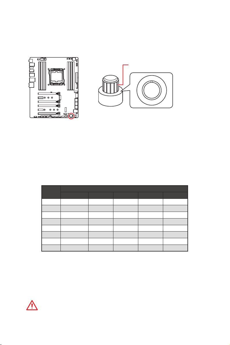
OC1: GAME BOOST Drehschalter
Mit diesem Drehschalter können Sie eine Stufe von Number 0 (Standard) zu Number
11 (Extremwert) auswählen, um die Prozessoren zu übertaken. Die Spannung und
Frequenz des CPUs wird dementsprechend automatisch angepasst, nachdem Sie
Ihren Computer einschalten.
GAME BOOST Drehschalter
0
1
1
1
0
1
GAME BOOST Drehschalter verwenden
Zum Einrichten des GAME BOOST Drehschalters befolgen Sie folgende Schritte:
1. Stellen Sie den GAME BOOST Drehschalter auf Hardware-Modus im BIOS-Setup.
Hinweis: Die LED des Drehschalters leuchtet auf wenn GAME BOOST durch die
Hardware gesteuert wird. Wenn die LED des Schalters nicht leuchtet, wird GAME
BOOST durch das BIOS gesteuert.
2. Schalten Sie den Computer aus.
3. Drehen Sie den GAME BOOST Drehschalter, um die benötigte Übertaktungsstufe
auszuwählen.
Stufe
4. Schalten Sie den Computer ein und GAME BOOST übertaktet die CPU abhängig
von der eingestellten Stufe.
GAME BOOST deaktivieren:
1. Stellen Sie den GAME BOOST Drehschalter auf HW-Modus im BIOS-Setup.
2. Schalten Sie den Computer aus.
3. Drehen Sie den GAME BOOST Drehschalter auf 0 und schalten Sie den PC ein. Die
Konfigurationsparameter werden auf die Normalwerte zurückgesetzt.
i5-7640X i7-7740X i7-7800X i7-7820X i9-7900X
0 4.0 GHz 4.3 GHz 3.5 GHz 3.6 GHz 3.3 GHz
1 4.5 GHz 4.8 GHz 4.1 GHz 4.4 GHz 4.4 GHz
2 4.6 GHz 4.9 GHz 4.2 GHz 4.5 GHz 4.5 GHz
4 4.7 GHz 5.0 GHz 4.3 GHz 4.6 GHz 4.6 GHz
6 4.8 GHz 5 .1 GHz 4.4 GHz 4.7 GHz 4.7 GHz
8 4.9 GHz 5.2 GHz 4.5 GHz 4.8 GHz 4.8 GHz
10 5.0 GHz 5.3 GHz 4.6 GHz 4.9 GHz 4.9 GHz
11 5 .1 GHz 5.4 GHz 4.7 GHz 5.0 GHz 5.0 GHz
CPU Frequenz
Wichtig
y
Bei der Verwendung der GAME BOOST- Funktion mit einem Prozessor der Core-X
Serie wird empfohlen, eine CPU Wasserkühlung mit Dual-Fan-Radiator einzusetzen
um eine bessere Kühlung und höhere Leistung zu gewährleisten.
2
4
8
6
Übersicht der Komponenten
27
Page 92

y
Sie können auch die GAME-Boost-Funktion im BIOS-Setup oder mit der MSI
COMMAND CENTER-Software steuern.
y
Nach Aktivierung der GAME BOOST Funktion lassen Sie die Einstellungen im BIOS
> OC Menü unverändert, um die Performance zu optimieren und die Stabilität des
System zu verbessern.
y
Der Erfolg der Übertaktung hängt von den Komponenten des Computers ab.
y
MSI gibt keine Garantie auf den GAME BOOST Übertaktungsbereich und auf
eventuelle Schäden, die durch eine Übertaktung entstehen können.
y
MSI-Komponenten werden für eine bessere GAME BOOST Kompatibilität empfohlen.
JSLOW1: Slow Mode Booting Steckbrücke
Die Steckbrücke wird für die LN2-Kühlungen verwendet. Der Slow Mode startet den
Prozessor in einer stabilen Frequenz und verhindert dadurch einen Systemcrash.
Normal
(Standardwert)
Steckbrücke während des
Die rote LED signalisiert,
dass sich die Slow-Mode
aktiviert ist.
Wichtig
y
Anwender übertakten bei extremer Kühlung auf eigenes Risiko. Die
Übertaktungsergebnisse werden abhängig von der CPU-Variante variieren.
y
Schalten Sie bitte nicht auf Enabled um, wenn das System ausgeschaltet ist, sonst
lässt es sich nicht starten.
Aktiviert
(Aktivieren Sie bitte diese
BIOS POST.)
JAUD1: Audioanschluss des Frontpanels
Dieser Anschluss ermöglicht den Anschluss von Audiobuchsen eines Frontpanels.
2 10
Übersicht der Komponenten
28
1
1 MIC L 2 Ground
3 MIC R 4 NC
5 Head Phone R 6 MIC Detection
7 SENSE_SEND 8 No Pin
9 Head Phone L 10 Head Phone Detection
9
Page 93

CPU_PWR1~2, ATX_PWR1: Stromanschlüsse
Mit diesen Anschlüssen verbinden Sie die ATX Stromstecker.
4
2 1
5
3
CPU)_PWR1
CPU_PWR2
8
4 1
1 Ground 5 +12V
2 Ground 6 +12V
3 Ground 7 +12V
4 Ground 8 +12V
1 Ground 3 +12V
2 Ground 4 +12V
1 +3.3V 13 +3.3V
2 +3.3V 14 -12V
3 Ground 15 Ground
24
12
JPWR1
131
4 +5V 16 PS-ON#
5 Ground 17 Ground
6 +5V 18 Ground
7 Ground 19 Ground
8 PWR OK 20 Res
9 5VSB 21 +5V
10 +12V 22 +5V
11 +12V 23 +5V
12 +3.3V 24 Ground
Wichtig
Stellen Sie sicher, dass alle Anschlüsse mit den richtigen Anschlüssen des Netzteils
verbunden sind, um einen stabilen Betrieb der Hauptplatine sicherzustellen.
Übersicht der Komponenten
29
Page 94

JFP1, JFP2: Frontpanel-Anschlüsse
Diese Anschlüsse verbinden die Schalter und LEDs des Frontpanels.
2 10
JFP1
1
9
1 HDD LED + 2 Power LED +
3 HDD LED - 4 Power LED -
5 Reset Switch 6 Power Switch
7 Reset Switch 8 Power Switch
9 Reserved 10 No Pin
1
JFP2
1 Speaker - 2 Buzzer +
3 Buzzer - 4 Speaker +
JUSB3, JUSB4: USB 3.1 Gen1 Anschlüsse
Mit diesen Anschlüssen können Sie die USB 3.1 Gen1 Anschlüsse auf dem Frontpanel
verbinden.
10 11
1
20
1 Power 11 USB2.0+
2 USB3_RX_DN 12 USB2.0-
3 USB3_RX_DP 13 Ground
4 Ground 14 USB3_TX_C_DP
5 USB3_TX_C_DN 15 USB3_TX_C_DN
6 USB3_TX_C_DP 16 Ground
7 Ground 17 USB3_RX_DP
8 USB2.0- 18 USB3_RX_DN
9 USB2.0+ 19 Power
10 Ground 20 No Pin
Wichtig
Bitte beachten Sie, dass Sie die mit „Stromführende Leitung“ und „Erdleitung“
bezeichneten Pins korrekt verbinden müssen, ansonsten kann es zu Schäden
kommen.
Übersicht der Komponenten
30
Page 95

Ladegerätanschluss
Der JUSB4 Anschluss ist ein Ladegerätanschluss, mit dem Sie die
Ladegeschwindigkeit Ihres Smartphones oder anderen USB-betriebenen Geräten
erhöhen. Der Ladegerätanschluss ist eine vom Mainboard-Chip gesteuerte Hardware,
die auch im Ruhezustand, Standby- oder im ausgeschalteten Modus Geräte aufladen
kann. Wenn Sie den Computer in Windows
CHARGER Anwendung installieren, um den Lademodus EIN/AUSZUSCHALTEN.
®
starten, müssen Sie die MSI® SUPER
Video-Demonstration
In diesem Video erfahren Sie, wie das MSI Super Charger funktioniert.
http://youtu.be/FCyvjr5NbOw
Wichtig
Wenn der Lademodus aktiviert ist, können Sie keine Daten über die Ladebuchse
synchronisieren.
JUSB5: USB 3.1 Gen2 Typ-C Anschluss
Mit diesem Anschluss können Sie den USB 3.1 Gen2 Typ-C Anschluss auf dem
Frontpanel verbinden. Der Anschluss verfügt über ein besonders sicheres Design.
Wenn Sie das Kabel anschließen, müssen Sie es in der entsprechenden Ausrichtung
verbinden.
JUSB5
USB Typ-C
Anschluss auf dem
Frontpanel
USB Typ-C Kabel
Übersicht der Komponenten
31
Page 96

JUSB1~2: USB 2.0 Anschlüsse
Mit diesen Anschlüssen können Sie die USB 2.0 Anschlüsse auf dem Frontpanel
verbinden.
2 10
1
1 VCC 2 VCC
3 USB0- 4 USB1-
5 USB0+ 6 USB1+
7 Ground 8 Ground
9 No Pin 10 NC
9
Wichtig
y
Bitte beachten Sie, dass Sie die mit VCC (Stromführende Leitung) und Ground
(Erdleitung) bezeichneten Pins korrekt verbinden müssen, ansonsten kann es zu
Schäden kommen.
y
Um ein iPad, iPhone und einen iPod über USB-Anschlüsse aufzuladen, installieren
Sie bitte die MSI
®
SUPER CHARGER Software.
JTPM1: TPM Anschluss
Dieser Anschluss wird für das TPM Modul (Trusted Platform Module) verwendet.
Weitere Informationen über den Einsatz des optionalen TPM Modules entnehmen Sie
bitte dem TPM Plattform Handbuch.
2 14
1
1 LPC Clock 2 3V Standby power
3 LPC Reset 4 3.3V Power
5 LPC address & data pin0 6 Serial IRQ
7 LPC address & data pin1 8 5V Power
9 LPC address & data pin2 10 No Pin
11 LPC address & data pin3 12 Ground
13 LPC Frame 14 Ground
13
Übersicht der Komponenten
32
Page 97

CPU_FAN1, PUMP_FAN1, SYS_FAN1~4: Stromanschlüsse für Lüfter
Diese Anschlüsse können im PWM (Pulse Width Modulation) Modus
oder Spannungsmodus betrieben werden. Im PWM-Modus bieten die
Lüfteranschlüsse konstante 12V Ausgang und regeln die Lüftergeschwindigkeit
per Drehzahlsteuersignal. Im DC-Modus bestimmen die Lüfteranschlüsse die
Lüftergeschwindigkeit durch Ändern der Spannung. Wenn Sie ein 3-Pin (Non-PWM)
Lüfter an einen PWM-Modus Lüfteranschluss anschließen, läuft der Lüfter mit
höchster Drehzahl und kann unangenehm laut werden. Folgen Sie den folgenden
Anweisungen, um den PWM- oder DC-Modus auszuwählen.
Lüfteranschlüsse mit automatischer Erkennung
1
CPU_FAN1/ PUMP _FAN1
1
SYS_FAN1~4
Wichtig
y
Sie können unter BIOS > HARDWARE MONITOR zwischen dem PWM- und DC-Modus
umschalten und die Lüfterdrehzahl ändern.
y
Überprüfen Sie die ordnungsgemäße Funktion der Lüfter nach dem Umschalten des
PWM-/ DC-Modus.
Pin-Belegung der Lüfteranschlüsse
Pin-Belegung des PWM-Modus
1 Ground 2 +12V
3 Sense 4 Speed Control Signal
Pin-Belegung des DC-Modus
1 Ground 2 Voltage Control
3 Sense 4 NC
VRAID1: Virtual RAID auf dem CPU Anschluss
Mit diesem Anschluss können Sie ein VROC (Virtual RAID on CPU) Tastenmodul
anschließen. Aktivieren Sie bitte die VROC-Funktion mit dem Treiber der Intel
®
(Intel
Rapid Storage Technology Enterprise).
1
1 GND 2 VCC3
3 GND 4 SATA_RAID_KEY
Wichtig
Das VROC-Modul muss separat erworben werden.
Übersicht der Komponenten
®
RSTe
33
Page 98

BIOS_SW1: Multi-BIOS Schalter
Das Motherboard hat zwei eigebaute BIOS ROMs (bezeichnet als A und B, Standard
ist BIOS ROM A). Falls ein BIOS abgestürzt ist, können Sie durch verschieben des
Schalters zum zweiten BIOS umschalten um zu starten.
BIOS A LED BIOS B LED
(Standardwert)
BIOS B BIOS A
BIOS wiederherstellen
Wenn ein BIOS-Update fehlgeschlagen ist und das System nicht gestartet werden
kann, können Sie die folgenden Schritte ausführen, um das BIOS wiederherzustellen.
Vor Wiederherstellung laden Sie bitte die neueste BIOS-Version, die dem
Motherboard-Modell entspricht, von der offiziellen MSI Website herunter. Und
speichern Sie die BIOS-Datei im Root-Verzeichnis des USB-Flash-Speichers.
1. Schalten Sie den Computer aus.
2. Wechseln Sie in den normalen BIOS ROM mit dem Multi-BIOS-Schalter.
3. Schließen das USB-Flashlaufwerk an den Computer an.
4. Schalten Sie den Computer ein und drücken Sie während des POST-Vorgangs die
Taste Del (Entf), um das BIOS zu öffnen.
5. Gehen Sie zu BIOS > M-FLASH und klicken Sie auf Yes (Ja), um das System neu zu
starten. Rufen Sie den Flash-Modus auf.
6. Wählen Sie die BIOS-Datei zur Durchführung des BIOS-Aktualisierungsprozesses
aus.
7. Setzen Sie den Schalter auf das ausgefallene BIOS mit dem Multi-BIOS-Schalter
um und klicken Sie auf Yes (Ja), um das BIOS wiederherzustellen.
8. Nachdem der BIOS-Wiederherstellungsprozess vollständig ist, startet das System
automatisch neu.
Wichtig
y
Bitte schalten Sie den Multi-BIOS-Schalter nicht um, während das System im
Betrieb ist.
y
Sie können auch das LIVE UPDATE oder BIOS FLASHBACK+ Utility verwenden, um
das BIOS zu flashen. Für weitere Erläuterungen verweisen wir Sie auf den BIOSBereich dieses Handbuchs.
Übersicht der Komponenten
34
Page 99

JBAT1: Clear CMOS Steckbrücke (Reset BIOS)
Der Onboard CMOS Speicher (RAM) wird durch eine externe Spannungsversorgung
durch eine Batterie auf dem Motherboard versorgt, um die Daten der
Systemkonfiguration zu speichern. Wenn Sie die Systemkonfiguration löschen wollen,
müssen Sie die Steckbrücke für kurze Zeit umsetzen.
Daten beibehalten
(Standardwert)
1. Rücksetzen des BIOS auf Standardwerte
2. Schalten Sie den Computer ab und ziehen Sie das Netzkabel ab.
3. Verwenden Sie eine Steckbrücke, um JBAT1 für 5-10 Sekunden kurzzuschließen.
4. Entfernen Sie die Steckbrücke von JBAT1.
5. Stecken Sie das Kabel Ihres Computers in die Steckdose hinein und schalten Sie
den Computer ein.
CMOS-Daten
löschen/ Reset
des BIOS
POWER1, RESET1: Power-Taste, Reset-Taste
Mit dieser Power-Taste können Sie den Computer einschalten. Mit der Reset-Taste
können Sie den Computer zurücksetzen.
Reset
Power-Taste
Reset-Taste
Übersicht der Komponenten
35
Page 100

JLED1: RGB LED Anschluss
Mit diesem Anschluss können Sie den 5050 RGB-LED-Streifen anschließen.
1
1 +12V 2 G
3 R 4 B
1
Verlängerungskabel
JLED1
5050 LED Streifen
Video-Demonstration
In diesem Video erfahren Sie, wie Sie die 5050 RGB LED Streifen am
RGB-LED-Anschluss anschließen können.
https://youtu.be/CqNHyADzd2Q
Wichtig
y
Dieser Anschluss unterstützt die 5050 RGB Mehr-Farb-LED-Streifen (12V/R/G/B)
mit der maximalen Leistung von 3A (12V). Beachten Sie bitte, dass die Länge des
LED-Streifens maximal 2 Meter betragen darf um eine Verdunkelung der LED zu
verhindern.
y
Schalten Sie die Stromversorgung aus und ziehen Sie das Netzkabel ab, bevor Sie
die RGB-LED-Streifen ein- und ausbauen.
y
Bitte verwenden Sie die MSI-Software zur Steuerung des LED-Leuchtstreifens.
JPWRLED1: Stromanschluss zur Demonstration des LEDLichteffekts
Dieser Anschluss ermöglicht es dem Fachhändler die integrierten LED-Lichteffekte
zu zeigen.
Übersicht der Komponenten
36
JPWRLED1 - LED Stromzufuhr
 Loading...