

Page 1
X2-109 Series
MS-9265 1U Rackmount Server
G52-92651X1
i
Page 2

Copyright Notice
The material in this document is the intellectual property of MICRO-STAR
INTERNATIONAL. We take every care in the preparation of this document, but no
guarantee is given as to the correctness of its contents. Our products are under
continual improvement and we reserve the right to make changes without notice.
Trademarks
All trademarks are the properties of their respective owners.
Intel® and Pentium® are registered trademarks of Intel Corporation.
AMD, Athlon™, Athlon™ XP, Thoroughbred™, and Duron™ are registered trade-
marks of AMD Corporation.
NVIDIA, the NVIDIA logo, DualNet, and nForce are registered trademarks or trade-
marks of NVIDIA Corporation in the United States and/or other countries.
PS/2 and OS®/2 are registered trademarks of International Business Machines
Corporation.
Windows® 95/98/2000/NT/XP are registered trademarks of Microsoft Corporation.
Netware® is a registered trademark of Novell, Inc.
Award® is a registered trademark of Phoenix Technologies Ltd.
AMI® is a registered trademark of American Megatrends Inc.
Revision History
Revision Revision History Date
V1.0 First release May 2008
Technical Support
If a problem arises with your system and no solution can be obtained from the user’ s
manual, please contact your place of purchase or local distributor. Alternatively,
please try the following help resources for further guidance.
Visit the MSI website at http://global.msi.com.tw/index.php?
func=service for FAQ, technical guide, BIOS updates, driver updates, and
other information.
Contact our technical staff at http://ocss.msi.com.tw.
ii
Page 3

Safety Instructions
1. Always read the safety instructions carefully.
2. Keep this User’s Manual for future reference.
3. Keep this equipment away from humidity.
4. Lay this equipment on a reliable flat surface before setting it up.
5. The openings on the enclosure are for air convection hence protects the equipment from overheating. DO NOT COVER THE OPENINGS.
6. Make sure the voltage of the power source and adjust properly 110/220V before connecting the equipment to the power inlet.
7. Place the power cord such a way that people can not step on it. Do not place
anything over the power cord.
8. Always Unplug the Power Cord before inserting any add-on card or module.
9. All cautions and warnings on the equipment should be noted.
10. Never pour any liquid into the opening that could damage or cause electrical
shock.
11. If any of the following situations arises, get the equipment checked by service
personnel:
The power cord or plug is damaged.
Liquid has penetrated into the equipment.
The equipment has been exposed to moisture.
The equipment does not work well or you can not get it work according to
User’s Manual.
The equipment has dropped and damaged.
The equipment has obvious sign of breakage.
12. DO NOT LEAVE THIS EQUIPMENT IN AN ENVIRONMENT UNCONDITIONED, STORAGE TEMPERATURE ABOVE 600 C (1400F), IT MAY DAMAGE THE EQUIPMENT.
CAUTION: Danger of explosion if battery is incorrectly replaced.
Replace only with the same or equivalent type recommended by
the manufacturer.
iii
Page 4

FCC-A Radio Frequency Interference Statement
This equipment has been
tested and found to comply
with the limits for a class A
digital device, pursuant to part
15 of the FCC rules. These limits are designed to provide reasonable protection
against harmful interference when the equipment is operated in a commercial
environment. This equipment generates, uses and can radiate radio frequency en-
ergy and, if not installed and used in accordance with the instruction manual, may
cause harmful interference to radio communications. Operation of this equipment in a
residential area is likely to cause harmful interference, in which case the user will be
required to correct the interference at his own expense.
Notice 1
The changes or modifications not expressly approved by the party responsible for
compliance could void the user’s authority to operate the equipment.
Notice 2
Shielded interface cables and A.C. power cord, if any, must be used in order to
comply with the emission limits.
VOIR LA NOTICE D’INSTALLATION AVANT DE RACCORDER AU RESEAU.
Micro-Star International
MS-9265
This device complies with Part 15 of the FCC Rules. Operation is subject to the
following two conditions:
(1) this device may not cause harmful interference, and
(2) this device must accept any interference received, including interference that
may cause undesired operation.
iv
Page 5
WEEE (Waste Electrical and Electronic Equipment) Statement
v
Page 6
vi
Page 7
vii
Page 8

CONTENTS
Copyright Notice...............................................................................................................ii
Trademarks.......................................................................................................................ii
Revision History...............................................................................................................ii
Technical Support............................................................................................................ii
Safety Instructions.........................................................................................................iii
FCC-A Radio Frequency Interference Statement........................................................iv
WEEE (Waste Electrical and Electronic Equipment) Statement....................................v
Chapter 1 Getting Started.....................................................................................1-1
System Overview...............................................................................................1-2
Mainboard Specifications...................................................................................1-6
Mainboard Layout................................................................................................1-9
Chapter 2 Hardware Setup....................................................................................2-1
Quick Components Guide....................................................................................2-2
CPU (Central Processing Unit)............................................................................2-3
Memory.................................................................................................................2-4
Power Supply......................................................................................................2-6
Back Panel I/O......................................................................................................2-7
Connector............................................................................................................2-8
Jumper................................................................................................................2-16
Slot......................................................................................................................2-17
System Assembly Flowchart...........................................................................2-18
System Assembly..............................................................................................2-19
Rack Mounting....................................................................................................2-30
Chapter 3 BIOS Setup.............................................................................................3-1
Entering Setup.....................................................................................................3-2
The Menu Bar......................................................................................................3-4
Main......................................................................................................................3-5
Advanced............................................................................................................3-6
Boot....................................................................................................................3-18
Security..............................................................................................................3-21
Chipset...............................................................................................................3-22
Exit......................................................................................................................3-25
Appendix A Intel ICH9R SATA RAID.....................................................................A-1
ICH9R Introduction...............................................................................................A-2
BIOS Configuration..............................................................................................A-3
Installing Driver....................................................................................................A-9
Installing Software............................................................................................A-11
viii
Page 9

RAID Migration Instructions...............................................................................A-15
Degraded RAID Array........................................................................................A-22
Appendix B LSI SAS RAID......................................................................................B-1
1. Introduction to Integrated RAID......................................................................B-2
2. Integrated Mirroring Overview.......................................................................B-3
3. Creating Integrated Mirroring Volumes..........................................................B-9
4. Integrated Striping Overview.......................................................................B-16
5. Creating Integrated Striping Volumes..........................................................B-19
ix
Page 10

x
Page 11

Getting Started
Chapter 1
Getting Started
Thank you for choosing the X2-109 (MS-9265 v1.X), a
high-performance barebone system from MSI.
Based on the innovative Intel® 5100 & ICH9R chipsets
for optimal system efficiency, the X2-109 accommodates the latest Intel® Xeon® (Dual-Core Wolfdale-DP/
Woodcrest & Quad-Core Clovertown/Harpertown) processors in Socket LGA771 and supports up to six DDR2
533/667MHz DIMM slots to provide the maximum of 48GB
memory capacity.
With high scalability, reliability, ease of use, and overall
value, the X2-109 makes an ideal choice for value conscious customers.
1-1
Page 12
MS-9265 Server
2
3
4
5
6
524
316
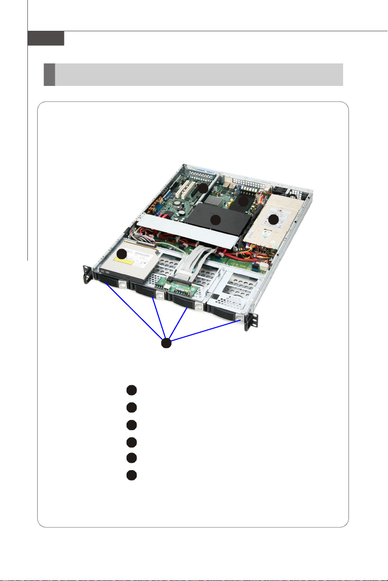
System Overview
Top View
1
HDD Tray
Slim DVD-ROM Drive
Fan Duct
PCI Expansion Card Bracket
Memory DIMM Slots
SSI EPS 1U Power Supply
1-2
Page 13
Getting Started
2
3
4
5
6
7
8
9
7984652
3
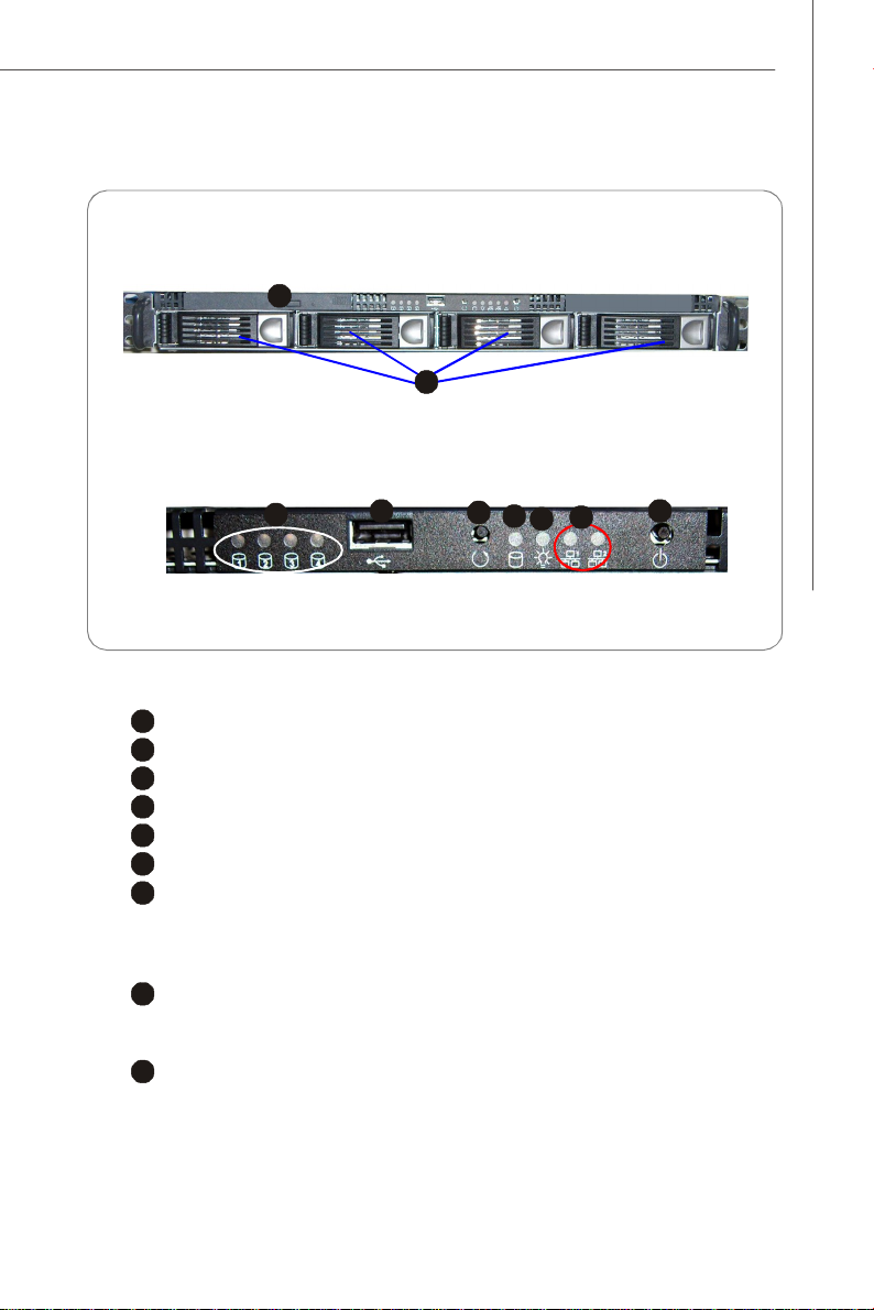
Front View
1
Front Bezel
1
Slim DVD-ROM Drive
Swappable Hard Disk Drive Bays
USB Port
System Reset Button
Power Button
HDD Power/Status LEDs
HDD Activity LED
This indicator shows the activity status of the hard disk drive. It flashes
when the system is accessing data on the hard disk and remains off when
no disk activity is detected.
Power LED
This indicator shows the power status of the system. It glows when the main
power is turned on.
Status LEDs of LAN# 1/2
1. The green LED is on when there is an active connection on the LAN port.
2. This LED flashes when transmitting or receiving activities to or from the
system are detected.
1-3
Page 14
MS-9265 Server
v Front Bezel LEDs
LED Color State Description
Green ON Power On
Green Blink S1/S3 Power/Sleep
/- OFF S4/S5
HDD Activity
LAN1 Activity
SAS/SATA
HDD1 LED
SAS/SATA
HDD2 LED
SAS/SATA
HDD3 LED
SAS/SATA
HDD4 LED
Green BLINK Hard Disk Drive Access
/- OFF No Access
Green ON LAN Link / No Access
Green BLINK LAN Access
/- OFF Idle
Green ON LAN Link / No Access
Green BLINK LAN Access LAN2 Activity
/- OFF Idle
Green BLINK HDD Access
Orange ON Drive Fails or Offline
Orange BLINK Drive is under Rebuild
Green BLINK HDD Access
Orange ON Drive Fails or Offline
Orange BLINK Drive is under Rebuild
Green BLINK HDD Access
Orange ON Drive Fails or Offline
Orange BLINK Drive is under Rebuild
Green BLINK HDD Access
Orange ON Drive Fails or Offline
Orange BLINK Drive is under Rebuild
1-4
Page 15
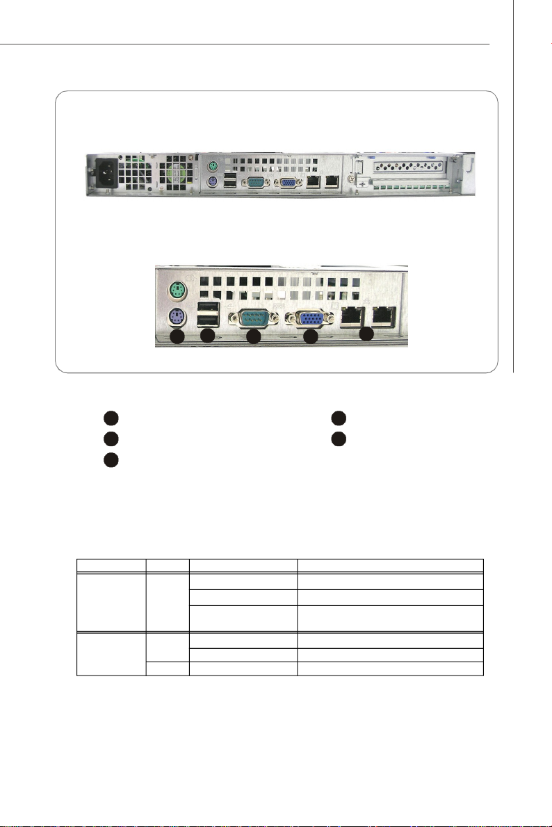
Rear View
2
3
4
5
234
5
Rear Bezel
1
PS/2 Keyboard/Mouse Connector
Serial Port
LAN Jacks
Getting Started
1
USB Ports
VGA Port
v Rear Bezel LEDs
LED Color LED State Condition
RJ45 NIC1 /
NIC2 Link /Activity
RJ45 NIC1 /
NIC2 Speed
Orange On (steady state) LAN link is established.
Green Off 10 Mbit/sec data rate is selected.
Orange On 1000 Mbit/sec data rate is selected.
Off LAN link is not established.
On (brighter & pulsing) The computer is communicating with another
On 100 Mbit/sec data rate is selected.
computer on the LAN.
1-5
Page 16
MS-9265 Server
System Specifications
Processor
- Supports Intel Xeon (Dual-Core Wolfdale-DP/Woodcrest & QuadCore Clovertown/Harpertown) processors in Socket LGA771
FSB
- FSB 1066/1333MHz
Chipset
- Northbridge: Intel 5100
- Southbridge: Intel ICH9R
Memory
- 6 DDR2 533/667 DIMM slots
- Maximum 48GB
LAN
- Supports dual Gigabit Ethernet by Intel 82573V & 82566DM
SAS
- 4 SAS ports by LSI Logic SAS1064E Host Controller
- Data transfer rate at up to 3Gb/s
SATA
- 6 SATAII ports support 6 SATAII devices
- Data transfer rate at up to 3Gb/s
1-6
IDE
- 1 IDE port by ITE IT8213F
- Supports Ultra DMA 66/100/133 mode
- Supports PIO, Bus Master operation mode
Floppy
- 1 floppy port
- Supports 1 FDD with 360KB, 720KB, 1.2MB, 1.44MB and 2.88MB
Graphics
- XGI Volari Z7 graphics processor
- 16MB graphics memory
Audio (Optional)
- Chip integrated by Realtek ALC888
- Flexible 2-channel audio with jack sensing
- Compliant with Azalia 1.0 Spec
Page 17
IPMI (Optional)
- Hitachi H8S/2168 IPMI microcontroller
Connectors
Back Panel
- 1 PS/2 mouse & PS/2 keyboard port
- 1 serial port
- 1 VGA port
- 2 USB 2.0 ports
- 2 RJ-45 Gigabit LAN ports
Onboard Connectors
- 2 USB 2.0 connectors
- 1 serial port connector
- 1 front panel audio connector
- 1 chassis intrusion connector
- 1 TPM connector
- 1 SPI Flash ROM connector (for debugging)
Slots
- 1 PCI-Express x16 slot
- 2 PCI-Express x8 slots (with x4 signal)
- 2 32-bit/33MHz PCI slots
Getting Started
Certification
- Safety: UL, CB, CCC
- EMC: FCC Class A, CE Class A
Chassis
- Form factor: 1U-22"
- Externally swappable HDD bay x 4
- Slim DVD drive bay x 1
- Full height slot x 1
- Chassis dimension: 569 x 430 x 43.5mm
Power Supply
- 500 watt
PFC function: Yes
Form factor: SSI EPS 1U
Safety mark: UL, cUL, TUV, CE-mark, CB
1-7
Page 18
MS-9265 Server
System Management
H8S BMC chip and MSI iConsole AP support IPMI 2.0
BMC Chip
- H8S 200-pin
- Host hardware interface: LPC interface
- Host software interface: KCS interface
Memory Size
- 256 X 16 Bits SRAM
Key Features
- IPMI 2.0 compliant
- Out-of-band LAN based management using RMCP
- FRU/SEL access
- Remote out-of-band alerts
- Event log
- Ability to update firmware inband unattended
- Remote access security (MD5)
- Out-of-band environmental monitoring and alerting
- Secure remote power control and system reset over Serial or
shared NIC (RMCP)
- Supports onboard I2C Winbond 83793G & Winbond 83627 to
extend hardware monitor feature
- Supports ASR (Automatic Server Restart)
System Management
- Three SMBus 2.0 (I2C)
- One SMBus for Intel ESB2E
- One SMBus for IPMB
- One SMBus for Winbond 83793G & Winbond 83627
- CPU fan speed control dependent on system temperature
- System fan speed control dependent on system temperature
Sensor Management
- Monitored Voltage: 12V, 5V, 3V, VBAT, VTT, Vcore, -12V
- Monitored Fan: 6 x System Fan, 2 x CPU Fan
1-8
Page 19
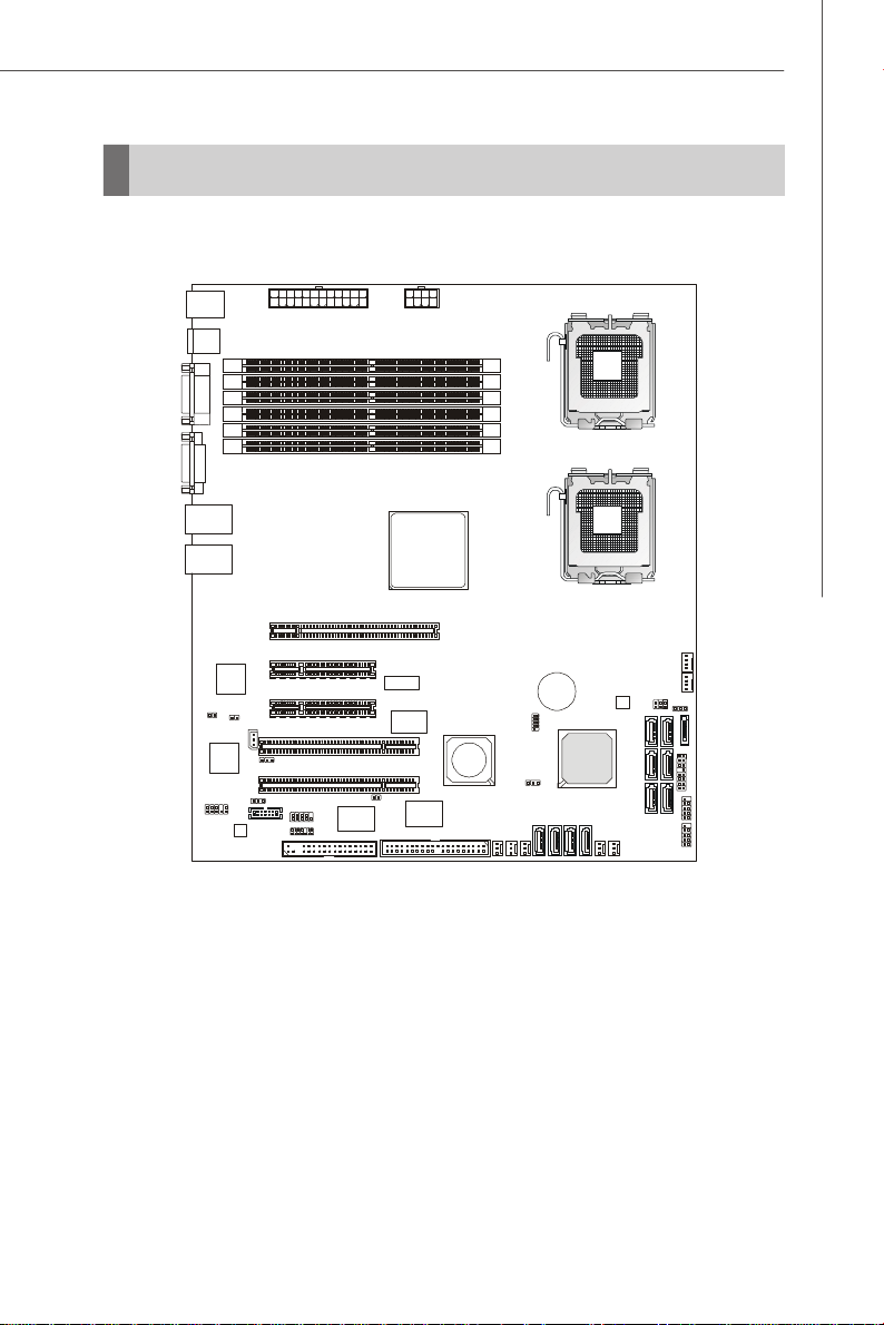
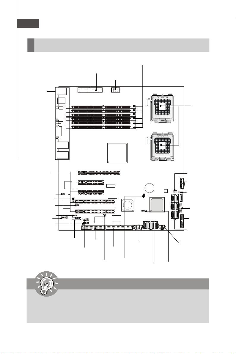
Mainboard Layout
PCIEX8_SLOT3
PCIEX8_SLOT2
IDE1
J_BOOT3
CPU_FAN1
CPU_FAN2
FDD1
SATA1J10SATA2SATA4SATA3
J21
J_CMOS1
T: Mouse
B: Keyboard
USB
Ports
COM1
VGA2
JLAN2
JLAN1
J_HB_RST1
BMC
Chip
JAUD1
XGI
Z7
J_BOOT2
Audio
Chip
J1
PCIEX16_SLOT1
J_IPMB1
PCI 1
J_ICMB1
PCI 2
J_BOOT1
COM2
JTPM1
JPWR1
JINT1
JPWR2
Intel
5100
iTE
IT8213F
LSISAS1064E
DIMMB1
DIMMA1
DIMMB2
DIMMA2
DIMMB3
DIMMA3
SYS_FAN5
Getting Started
CPU1
CPU2
BATT
+
JSPI1
Intel
ICH9R
SAS_2
SAS_3
SAS _1
SAS _4
SYS_FAN1
SYS_FAN 3
SYS_FA N4
SYS_FAN 2
J22
SATA5
SATA6
JUSB 2
JUSB3
5100 Master (MS-9665 v1.X) SSI CEB Server Board
1-9
Page 20

MS-9265 Server
1-10
Page 21
Hardware Setup
Chapter 2
Hardware Setup
Refer to the system assembly flowchart and the chart
below to determine the proper sequence of removing
or installing components to the server.
MS-9265
Mainboard Hardware
System Assembly
Rack Mounting
CPU, Memory, Power Supply, Back
Panel, Connector, Jumper, Slot
Chassis Cover
CPU, Heatsink
Memory
Expansion Card
Hard Disk Drive
2-1
Page 22
MS-9265 Server
Quick Components Guide
JPWR1, p.2-6
Back Panel
I/O, p.2-7
DIMM Slots, p.2-4
JPWR2, p.2-6
CPU, p.2-3
PCI-Class
Slots, p.2-17
J_H8_RST1,
J_BOOT2, p.2-11
J_IPMB1, p.2-11
J_ICMB1, p.2-11
J_BOOT1, p.2-11
JAUD1, p.2-14
JTPM1, p.2-13
J1, p.2-11
COM2, p.2-12
FDD1,
p.2-8
JINT1, p.2-10
IDE1,
p.2-8
SYS_FAN3~5,
p.2-10
JSPI1,
p.2-13
SAS_1~4,
p.2-9
SYS_FAN1~2,
p.2-10
J_BOOT3,
p.2-16
Important
CAUTION!!! Please note that the CPU1/CPU2 VRM & memory/south bridge
area should be respectively kept under 105oC and 85oC. To ensure system
stability, always protect the system with proper cooling. Otherwise, overheating may damage the system.
2-2
J21, p.2-15
CPU_FAN1~2,
p.2-10
J_CMOS1,
p.2-16
J22, p.2-15
JUSB2~3,
p.2-12
SATA1~6,
p.2-9
Page 23
Hardware Setup
CPU (Central Processing Unit)
This mainboard supports the latest Intel® Xeon® (Dual-Core Wolfdale-DP/Woodcrest &
Quad-Core Clovertown/Harpertown) processors in Socket LGA771. When you are
installing the CPU, make sure that you install the cooler to prevent the CPU from
overheating. If you do not have a CPU cooler, contact your dealer to purchase and
install them before turning on the computer.
Important
1. Overheating will seriously damage the CPU and system. Always make
sure the cooling fan can work properly to protect the CPU from overheating.
2. Make sure that you apply an even layer of heat sink paste (or thermal tape)
between the CPU and the heatsink to enhance heat dissipation.
3. While replacing the CPU, always turn off the power supply or unplug the
power supply’s power cord from the grounded outlet first to ensure the
safety of CPU.
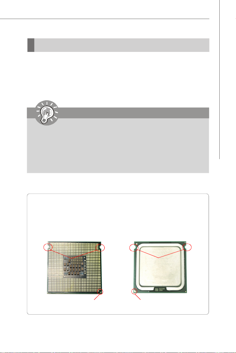
Introduction to LGA 771 CPU
The pin-pad side of LGA 771 CPU.
Alignment Key
Yellow triangle is the Pin 1 indicator
The surface of LGA 771 CPU.
Remember to apply some silicone
heat transfer compound on it for
better heat dispersion.
Alignment Key
Yellow triangle is the Pin 1 indicator
2-3
Page 24
MS-9265 Server
Empty
Installed
DIMMB1
DIMMB2
DIMMB3
DIMMA1
DIMMA2
DIMMA3
DIMMB1
DIMMB2
DIMMB3
DIMMA1
DIMMA2
DIMMA3
DIMMB1
DIMMB2
DIMMB3
DIMMA1
DIMMA2
DIMMA3
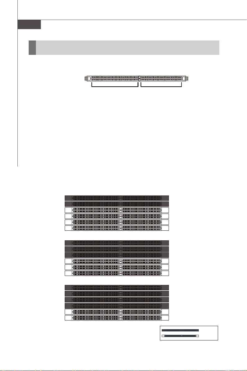
Memory
These DIMM slots are intended for system memory modules.
DDR2
240-pin, 1.8V
64x2=128 pin 56x2=112 pin
Dual-Channel Mode Population Rule
In Dual-Channel mode, the memory modules can transmit and receive data with two
data bus lines simultaneously. Dual-Channel mode is enabled when the installed
memory capacities of both DIMM channels are equal. If different speed DIMMs are
used between channels, the slowest memory timing will be used.
Dual-Channel mode can be achieved with two, three or four DIMMs. To achieve DualChannel mode, the following conditions must be met:
* Matched DIMM configuration in each channel
* Same Density (512MB, 1GB, 2GB, etc.)
* Matched in both Channel A and Channel B memory channels
* Populate symmetrical memory slots
Configurations that do not match the above conditions will revert to Single-Channel
mode.
2 DIMMs
2GB
2GB
3 DIMMs
1GB
2GB
1GB
4 DIMMs
2GB
2GB
1GB
1GB
2-4
Page 25
Hardware Setup
DIMMB1
DIMMB2
DIMMB3
DIMMA1
DIMMA2
DIMMA3
DIMMB1
DIMMB2
DIMMB3
DIMMA1
DIMMA2
DIMMA3
5 DIMMs
6 DIMMs
2GB
2GB
1GB
2GB
1GB
2GB
2GB
2GB
2GB
1GB
1GB
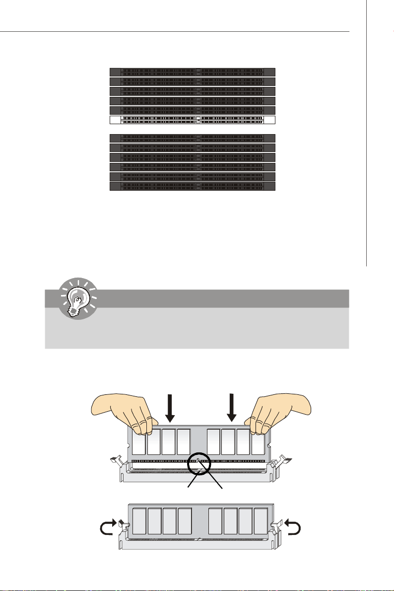
Installing Memory Modules
1. Locate the DIMM slots on the mainboard. Flip open the retaining clip at each side
of the DIMM slot.
2. Align the notch on the DIMM with the key on the slot. Insert the DIMM vertically into
the DIMM slot. Then push it in until the golden finger on the DIMM is deeply inserted
in the DIMM slot. The retaining clip at each side of the DIMM slot will automatically
close if the DIMM is properly seated.
Important
You can barely see the golden finger if the DIMM is properly inserted in the
DIMM slot.
3. Manually check if the DIMM has been locked in place by the retaining clips at the
sides.
4. Follow the same procedures to install more DIMMs if necessary.
Volt
Notch
2-5
Page 26
MS-9265 Server
Power Supply
System Power Connector: JPWR1
This connector allows you to connect to an SSI power supply. To connect to the SSI
power supply, make sure the plug of the power supply is inserted in the proper
orientation and the pins are aligned. Then push down the power supply firmly into the
connector.
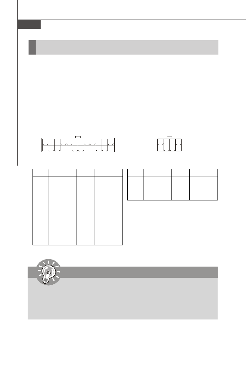
12V CPU Power Connector: JPWR2
This connector provides 12V power output to the CPUs.
JPWR2
8 5
4
JPWR2 Pin Definition
1
PIN SIGNAL
5 +12V
6 +12V
7 +12V
8 +12V
24
12
JPWR1 Pin Definition
PIN SIGNAL
1 +3.3V
2 +3.3V
3 GND
4 +5V
5 GND
6 +5V
7 GND
8 PWR OK
9 5VSB
10 +12V
11 +12V
12 +3.3V
JPWR1
PIN SIGNAL
13 +3.3V
14 -12V
15 GND
16 PS-ON#
17 GND
18 GND
19 GND
20 Res
21 +5V
22 +5V
23 +5V
24 GND
13
1
PIN SIGNAL
1 GND
2 GND
3 GND
4 GND
Important
1. Make sure that all power connectors are connected to proper power supplies
to ensure stable operation of the mainboard.
2. Power supply of 600 watts (and above) is highly recommended for system
stability.
3. SSI 12V power connection should be greater than 18A.
2-6
Page 27
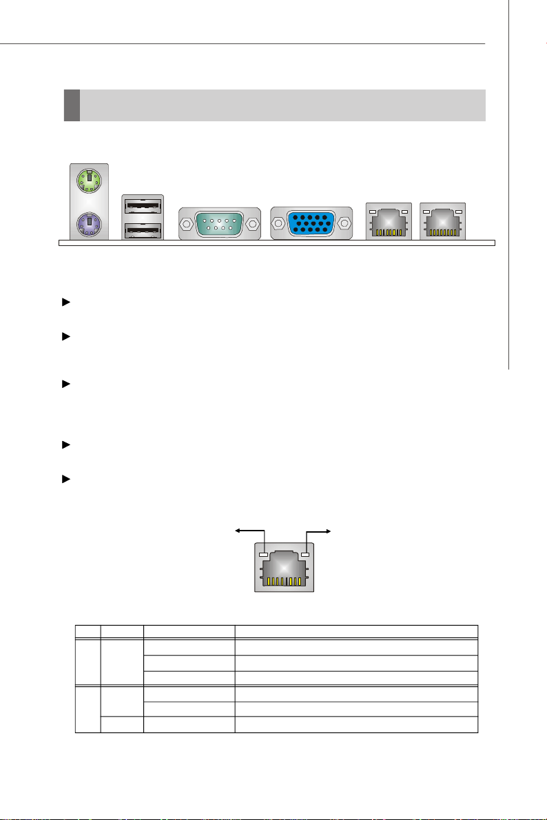
Back Panel I/O
Mouse
Hardware Setup
Keyboard
Serial PortUSB Ports VGA Port
LAN Jacks
Mouse/Keyboard
The standard PS/2® mouse/keyboard DIN connector is for a PS/2® mouse/keyboard.
USB Port
The USB (Universal Serial Bus) port is for USB devices such as keyboard, mouse, or
other USB-compatible devices.
Serial Port
The serial port is a 16550A high speed communications port that sends/ receives 16
bytes FIFOs. You can attach a serial mouse or other serial devices directly to the
connector.
VGA Port
The DE-15 female connector is provided for monitor.
LAN
The standard RJ-45 LAN jack is for connection to Local Area Network (LAN). You
can connect a network cable to it.
Link/Active Indicator
RJ-45 LAN Jack
LED Color LED State Condition
Off LAN link is not established.
Left Orange On (steady state) LAN link is established.
On (brighter & pulsing)The computer is communicating with another computer on the LAN.
Green Off 10 Mbit/sec data rate is selected.
Right On 100 Mbit/sec data rate is selected.
Orange On 1000 Mbit/sec data rate is selected.
Mode Indicator
2-7
Page 28
MS-9265 Server
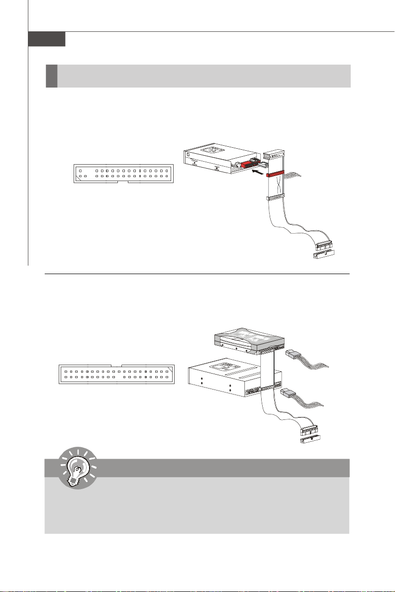
Connector
Floppy Disk Drive Connector: FDD1
This connector supports 360KB, 720KB, 1.2MB, 1.44MB or 2.88MB floppy disk drive.
FDD1
IDE Connector: IDE1
This connector supports IDE hard disk drives, optical disk drives and other IDE devices.
IDE1
Important
If you install two IDE devices on the same cable, you must configure the
drives separately to master / slave mode by setting jumpers. Refer to IDE
device’s documentation supplied by the vendors for jumper setting
instructions.
2-8
Page 29
Hardware Setup
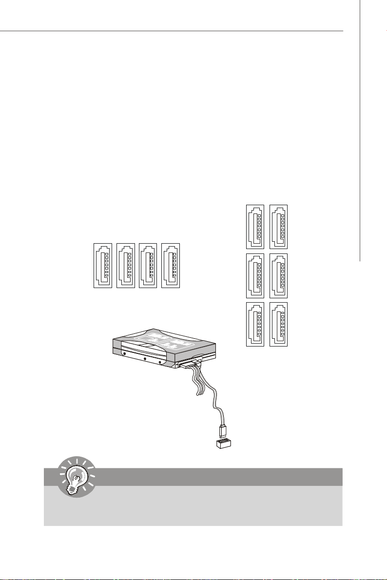
Serial Attached SCSI Connector: SAS_1 ~ SAS_4
The SAS connector is a new generation serial communication protocol for devices
designed to allow for much higher speed data transfers. It supports data transfer
speeds up to 3 Gbit/s. SAS uses serial communication instead of the parallel method
found in traditional SCSI devices but still uses SCSI commands for interacting with
SAS devices. Each SAS connector can connect to 1 disk drive.
Serial ATA Connector: SATA1 ~ SATA6
This connector is a high-speed Serial ATA interface port. Each connector can connect to one Serial ATA device.
SAS_2
SAS_1
SAS_3
SAS_4
SATA2
SATA4
SATA6
SATA1
SATA3
SATA5
Important
Please do not fold the SATA/SAS accessory cable into 90-degree angle.
Otherwise, data loss may occur during transmission.
2-9
Page 30
MS-9265 Server
Chassis Intrusion Switch Connector: JINT1
This connector connects to the chassis intrusion switch cable. If the chassis is
opened, the chassis intrusion mechanism will be activated. The system will record
this status and show a warning message on the screen. To clear the warning, you
must enter the BIOS utility and clear the record.
C
I
N
G
T
N
R
D
U
2
1
JINT1
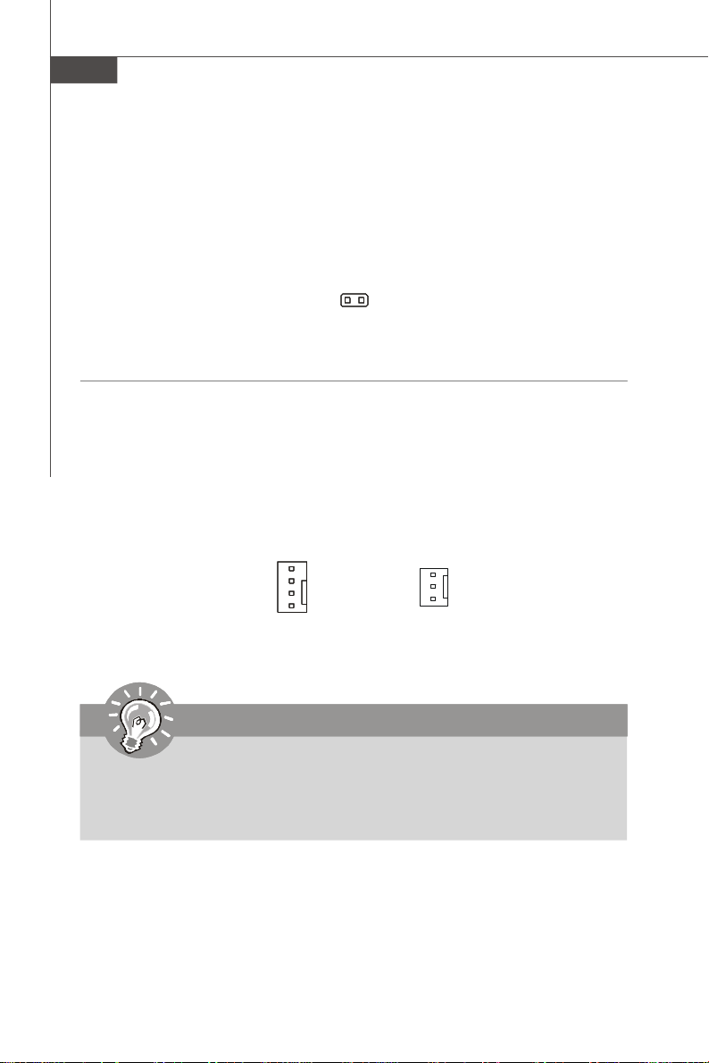
Fan Power Connector: CPU_FAN1 / 2, SYS_FAN1 / 2 / 3 / 4 / 5
The fan power connectors support system cooling fan with +12V. When connecting
the wire to the connectors, always note that the red wire is the positive and should
be connected to the +12V; the black wire is Ground and should be connected to GND.
If the mainboard has a System Hardware Monitor chipset onboard, you must use a
specially designed fan with speed sensor to take advantage of the CPU fan control.
CONTROL
SENSOR
+12V
GND
CPU_FAN1/2
SENSOR
+12V
GND
SYS_FAN1/2/3/4/5
Important
1.Please refer to the recommended CPU fans at processor’s official website
or consult the vendors for proper CPU cooling fan.
2.Users are suggested to enter the BIOS Setup Utility to set up the Smart Fan
Control function.
2-10
Page 31

Hardware Setup
BMC Connector: J_BOOT1, J_BOOT2, J_H8_RST1, J_IPMB1,
J_ICMB1, J1
These connectors are used to control the H8 BMC (Baseboard Management
Controller).
J_BOOT1
1
Pin Definition
PIN SIGNAL
1 BOOT_TXD_CON
2 BOOT_RXD_CON
3 GND
Pin Definition
PIN SIGNAL
1 IPMB_DATA
2 GND
3 IPMB_CLK
PIN SIGNAL PIN SIGNAL
1 ETCK 2 GND
3 ETRST# 4 GND
5 ETDO 6 GND
7 H2C_RES# 8 3.3V DUAL
9 ETMS 10 GND
11 ETDI 12 GND
13 H8_RESET# 14 GND
J_IPMB1
1
J_BOOT2
1
Pin Definition
PIN SIGNAL
1 Boot Mode
2 GND
J1
13
14
Pin Definition
J_ICMB1
1
Pin Definition
PIN SIGNAL
1 BMC_RXD0
2 BMC_TXD0
3 ICMB_EN
1
2
J_H8_RST1
1
Pin Definition
PIN SIGNAL
1 H8_RESET
2 GND
2-11
Page 32

MS-9265 Server
Serial Port Connector: COM2
This connector is a 16550A high speed communications port that sends/receives 16
bytes FIFOs. You can attach a serial device to it.
Pin Definition
PIN SIGNAL DESCRIPTION
COM2
2
1 9
1 DCD Data Carry Detect
2 SIN Serial In or Receive Data
3 SOUT Serial Out or Transmit Data
4 DTR Data Terminal Ready
5 GND Ground
6 DSR Data Set Ready
7 RTS Request To Send
8 CTS Clear To Send
9 RI Ring Indicate
Front USB Connector: JUSB2, JUSB3
This connector, compliant with Intel® I/O Connectivity Design Guide, is ideal for connecting high-speed USB interface peripherals such as USB HDD, digital cameras,
MP3 players, printers, modems and the like.
Pin Definition
10
1 2
JUSB2/3
9
PIN SIGNAL PIN SIGNAL
1 VCC 2 VCC
3 USB0- 4 USB1-
5 USB0+ 6 USB1+
7 GND 8 GND
9 Key (no pin) 10 NC
USB 2.0 Bracket
(Optional)
Important
Note that the pins of VCC and GND must be connected correctly to avoid
possible damage.
2-12
Page 33

Hardware Setup
SPI Flash ROM Connector: JSPI1
This connector is used to flash SPI flash ROM.
Pin Definition
JSPI1
1
9
2
10
Pin Description Pin Description
1 VCC3_SB 2 VCC3_SB
3 SPI_MISO_F 4 SPI_MOSI_F
5 SPI_CS0_F# 6 SPI_CLK_F
7 GND 8 GND
9 SPI_HOLD# 10 NC
TPM Connector: JTPM1 (Optional)
This connector connects to an optional TPM (Trusted Platform Module). Please refer
to the TPM security platform manual for more details.
JTPM1
2
1
14
13
PIN SIGNAL DESCRIPTION PIN SIGNAL DESCRIPTION
1 LCLK LPC clock 2 3V dual/3V_STB 3V dual or 3V standby power
3 LRST# LPC reset 4 VCC3 3.3V power
5 LAD0 LPC address & data pin0 6 SIRQ Serial IRQ
7 LAD1 LPC address & data pin1 8 VCC5 5V power
9 LAD2 LPC address & data pin2 10 KEY No pin
11 LAD3 LPC address & data pin3 12 GND Ground
13 LFRAME# LPC Frame 14 GND Ground
2-13
Page 34

MS-9265 Server
Front Panel Audio Connector: JAUD1
This connector allows you to connect the front panel audio and is compliant with
Intel® Front Panel I/O Connectivity Design Guide.
JAUD1
2
1
HD Audio Pin Definition
PIN SIGNAL DESCRIPTION
1 MIC_L Microphone - Left channel
2 GND Ground
3 MIC_R Microphone - Right channel
4 PRESENCE# Active low signal-signals BIOS that a High Definition Audio dongle
5 LINE out_R Analog Port - Right channel
6 MIC_JD Jack detection return from front panel microphone JACK1
7 Front_JD Jack detection sense line from the High Definition Audio CODEC
8 NC No control
9 LINE out_L Analog Port - Left channel
10 LINEout_JD Jack detection return from front panel JACK2
is connected to the analog header. PRESENCE# = 0 when a
High Definition Audio dongle is connected
jack detection resistor network
10
9
2-14
Page 35

Hardware Setup
I2C Bus Connector: J21
This connector, known as I2C, is used to connect System Management Bus (SMBus)
interface.
Pin Definition
J21
5 1
6
2
PIN SIGNAL
1 SMBUS_SDA
2 GND
3 SMBUS_SCL
4 5VCC
5 SMBUS_ALERT#
6 PCIRST#
Front Panel Connector: J22
The mainboard provides one front panel connector for electrical connection to the
front panel switches and LEDs.
J22
16
15
1
2
J22 Pin Definition
PIN SIGNAL DESCRIPTION
1 HDD_LED + HDD LED +
2 PLED Power LED
3 HDD_LED - HDD LED -
4 SLED Suspend LED
5 FP_RST+ Front Panel Reset +
6 FP_BTN - Front Panel Button -
7 FP_RST- Front Panel Reset -
8 GND Ground
9 NC No connection
10 KEY Key
11 SYS_FAULT_H8S System fault LED
12 ID_LED_H8S System ID LED
13 NC No connection
14 LAN1_LED LAN1 LED
15 NC No connection
16 LAN2_LED LAN2 LED
2-15
Page 36

MS-9265 Server
Jumper
BIOS Recovery Jumper: J_BOOT3
Users can short connect pin#2-3 to recover the system BIOS with a Recovery
Floppy. When the system is done with the job, the buzzer will beep to remind the user
to set the jumper to its normal state (pin#1-2 short connected).
1
J_BOOT3
1 3
Normal
1 3
Recovery
Clear CMOS Jumper: J_CMOS1
There is a CMOS RAM onboard that has a power supply from an external battery to
keep the data of system configuration. With the CMOS RAM, the system can automatically boot OS every time it is turned on. If you want to clear the system configuration,
set the jumper to clear data.
1
J_CMOS1
1 3
Keep Data
1 3
Clear Data
Important
You can clear CMOS by shorting 2-3 pin while the system is off. Then return
to 1-2 pin position. Avoid clearing the CMOS while the system is on; it will
damage the mainboard.
2-16
Page 37

Hardware Setup
Slot
PCI (Peripheral Component Interconnect) Express Slot
The PCI Express slot supports the PCI Express interface expansion card.
The PCI Express x 16 slot supports up to 4.0 GB/s transfer rate.
The PCI Express x 8 slot supports up to 2.0 GB/s transfer rate.
PCI Express x16 Slot
PCI Express x8 Slot
PCI (Peripheral Component Interconnect) Slot
The PCI slot supports LAN card, SCSI card, USB card, and other add-on cards that
comply with PCI specifications.
32-bit PCI Slot
Important
When adding or removing expansion cards, make sure that you unplug the
power supply first. Meanwhile, read the documentation for the expansion card
to configure any necessary hardware or software settings for the expansion
card, such as jumpers, switches or BIOS configuration.
PCI Interrupt Request Routing
The IRQ, acronym of interrupt request line and pronounced I-R-Q, are hardware lines
over which devices can send interrupt signals to the microprocessor. The PCI IRQ
pins are typically connected to the PCI bus pins as follows:
DEVICE IDSEL INT A INT B INT C INT D REQ GNT
PCI
PCI
IT8213F
AD20 PCI_PIRQ#0 PCI_PIRQ#1 PCI_PIRQ#2 PCI_PIRQ#3 PCI_REQ#0 PCI_GNT#0
AD21 PCI_PIRQ#3 PCI_PIRQ#0 PCI_PIRQ#0 PCI_PIRQ#2 PCI_REQ#1 PCI_GNT#1
AD1921 PCI_PIRQ#2 PCI_REQ#2 PCI_GNT#21
2-17
Page 38

MS-9265 Server
START
System Assembly Flowchart
The following flowchart shows basic system assembly procedures. Please note
that always wear anti-static gloves when handling electrical components and exercise caution during the installation process. For more information, contact your local
dealer or experienced technician.
REMOVE CHASSIS COVER
INSTALL
INSTALL
CPU & HEATSINK
HARD DISK DRIVES
INSTALL
MEMORY MODULES
INSTALL
PCI EXPANSION CARDS
2-18
CHECK IF ALL PARTS
ARE PROPERLY CONNECTED
REPLACE
CHASSIS COVER
FINISH
Page 39

Hardware Setup
System Assembly
Removing the Chassis Cover
1. Unscrew the chassis cover.
2. Press the release buttons and slide the chassis cover forwards.
3. Lift up the cover and remove it from
the chassis.
2-19
Page 40

MS-9265 Server
Replacing the Chassis Cover
1. Replace the chassis cover and slide it backwards.
2. Screw to secure the chassis cover.
Important
Before you remove or install any components, make sure the server is not
turned on or connected to the AC power.
2-20
Page 41

Hardware Setup
CPU, Heatsink, and Fan Duct
1. On top of the CPU is a fan duct designed to enhance heat dissipation of the CPU.
Lift up & remove the fan duct before installing the CPU.
2. Locate the first CPU socket. (The CPU has a plastic cap on it to protect the contact
from damage. Before installing the CPU, always cover it to protect the socket
pins.)
3. Remove the plastic cap from the load plate. The pins of the socket reveal.
CPU2
CPU1
4. Raise the load lever up to its full extent.5. Open the load plate.
2-21
Page 42

MS-9265 Server
6. After confirming the CPU direction (indicated below with red circles) for correct mating, put down
the CPU in the socket housing frame. Be sure to
grasp on the edge of the CPU base. Note that the
Alignment Key
alignment keys are matched.
7. Visually inspect if the CPU is seated well into the
socket. If not, take out the CPU with pure vertical
motion and reinstall.
Yellow triangle is the Pin 1 indicator
8. Cover the load plate onto the package.
9. Press down the load lever lightly onto the load plate and then secure the lever
with the hook under the retention tab.
10.Follow the same procedures to install
the second CPU.
Note: To install DUAL CPUs
on the board, you must use
the same types of CPUs
running at the same FSB
frequency.
2-22
Page 43

Hardware Setup
11.Place the heat sink on top of CPU1 and secure the screws on both sides.
Note: The heat sink has to be installed to prevent the CPU from overheating.
12.Follow the same procedures to install the second heatsink.
2-23
Page 44

MS-9265 Server
Memory
1. Locate the DIMM slots on the mainboard. Insert the memory module vertically into
the DIMM slot. Then push it in until the golden finger on the memory module is
deeply inserted in the DIMM slot. The plastic clip at each side of the DIMM slot will
automatically close.
2. Follow the same procedures to install more memory modules if necessary.
3. Replace the fan duct on top of the
heatsinks and the memory DIMMs.
Note: To ensure proper cooling,
make sure the heatsinks & the fan
duct are properly installed.
2-24
Page 45

Hardware Setup
DIMMB1
DIMMB2
DIMMB3
DIMMA1
DIMMA2
DIMMA3
DIMMB1
DIMMB2
DIMMB3
DIMMA1
DIMMA2
DIMMA3
DIMMB1
DIMMB2
DIMMB3
DIMMA1
DIMMA2
DIMMA3
DIMMB1
DIMMB2
DIMMB3
DIMMA1
DIMMA2
DIMMA3
DIMMB1
DIMMB2
DIMMB3
DIMMA1
DIMMA2
DIMMA3
Dual-Channel Mode Population Rule
In Dual-Channel mode, the memory modules can transmit and receive data with two
data bus lines simultaneously. Dual-Channel mode is enabled when the installed
memory capacities of both DIMM channels are equal. If different speed DIMMs are
used between channels, the slowest memory timing will be used.
Dual-Channel mode can be achieved with two, three or four DIMMs. To achieve DualChannel mode, the following conditions must be met:
* Matched DIMM configuration in each channel
* Same Density (512MB, 1GB, 2GB, etc.)
* Matched in both Channel A and Channel B memory channels
* Populate symmetrical memory slots
Configurations that do not match the above conditions will revert to Single-Channel
mode.
2 DIMMs
2GB
2GB
3 DIMMs
4 DIMMs
5 DIMMs
6 DIMMs
1GB
2GB
1GB
2GB
2GB
1GB
1GB
2GB
2GB
1GB
2GB
1GB
2GB
2GB
2GB
2GB
1GB
1GB
2-25
Page 46

MS-9265 Server
Expansion Card
1. Locate the riser card bracket and lift it up from the chassis.
2. Unscrew the cover plate and put it aside for later use.
2-26
Page 47

Hardware Setup
3. Insert the expansion card into the PCI-Express slot on the riser card.
4. Screw to secure the expansion card bracket.
5. Place the riser card bracket on top of the PCI-Express slot on the motherboard.
Align the riser card golden fingers with the PCI-Express slot.
6. Push the riser card bracket carefully down with even force on both sides.
2-27
Page 48

MS-9265 Server
Hard Disk Drive
1. To release the hot-swapping HDD tray, flip open the tray lever and pull the tray
out of the bay.
2. At the rear of the HDD are four screw holes, two on the right and two on the left
side. At the back of the HDD rack are four identical screw holes as on the HDD.
Place the HDD into the rack and align the screw holes on the HDD with the ones
on the rack. Secure the HDD with four screws supplied by the HDD vendor.
2-28
Page 49

3. Insert the HDD tray into the bay and
push the tray lever back in place.
Hardware Setup
2-29
Page 50

MS-9265 Server
Rack Mounting
1. Pull the inner channel out.
latch
Press the latch to
disconnect.
2. Assemble the inner rail to the chassis.
Fasten 6 screws at least to attach the inner channel onto the chassis.
2-30
M4 screw
Page 51

3. Mount the L-shaped bracket onto the outer channel.
Hardware Setup
FRONT
Use black round head
screws.
4. Mount the slides to the vertical racks.
Type A
M4 screw
Type B
M5 screw
BACK
black screw
shall be in flush position
washer
Type C
M5 screw
2-31
Page 52

MS-9265 Server
5. Insert the chassis into the frame.
2-32
Page 53

Chapter 3
BIOS Setup
This chapter provides information on the BIOS Setup
program and allows you to configure the system for
optimum use.
You may need to run the Setup program when:
² An error message appears on the screen during the
system booting up, and requests you to run SETUP.
² You want to change the default settings for cus-
tomized features.
BIOS Setup
3-1
Page 54

MS-9265 Server
Entering Setup
Power on the computer and the system will start POST (Power On Self Test) process.
When the message below appears on the screen, press <Del> key to enter Setup.
Press Del to enter SETUP
If the message disappears before you respond and you still wish to enter Setup,
restart the system by turning it OFF and On or pressing the RESET button. You may
also restart the system by simultaneously pressing <Ctrl>, <Alt>, and <Delete> keys.
Important
1.The items under each BIOS category described in this chapter are under
continuous update for better system performance. Therefore, the description may be slightly different from the latest BIOS and should be held for
reference only.
2.Upon boot-up, the 1st line appearing after the memory count is the BIOS
version. It is usually in the format:
3-2
A9265IMS V1.0 051508 where:
1st digit refers to BIOS maker as A = AMI, W = AWARD, and P =
PHOENIX.
2nd - 5th digit refers to the model number.
6th digit refers to the chipset as I = Intel, N = nVidia, and V = VIA.
7th - 8th digit refers to the customer as MS = all standard customers.
V1.0 refers to the BIOS version.
051508 refers to the date this BIOS was released.
Page 55

BIOS Setup
Control Keys
<↑> Move to the previous item
<↓> Move to the next item
<←> Move to the item in the left hand
< →> Move to the item in the right hand
<Enter> Select the item
<Esc> Jumps to the Exit menu or returns to the main menu from a
submenu
<+/PU> Increase the numeric value or make changes
<-/PD> Decrease the numeric value or make changes
<F8> Load Optimized Defaults
<F9> Load Fail-Safe Defaults
<F10> Save all the CMOS changes and exit
Getting Help
After entering the Setup menu, the first menu you will see is the Main Menu.
Main Menu
The main menu lists the setup functions you can make changes to. You can use the
arrow keys ( ↑↓ ) to select the item. The on-line description of the highlighted setup
function is displayed at the bottom of the screen.
Sub-Menu
If you find a right pointer symbol (as shown in the right
view) appears to the left of certain fields that means a submenu can be launched from this field. A sub-menu contains
additional options for a field parameter. You can use arrow keys ( ↑↓ ) to highlight the
field and press <Enter> to call up the sub-menu. Then you can use the control keys
to enter values and move from field to field within a sub-menu. If you want to return
to the main menu, just press the <Esc >.
General Help <F1>
The BIOS setup program provides a General Help screen. You can call up this screen
from any menu by simply pressing <F1>. The Help screen lists the appropriate keys
to use and the possible selections for the highlighted item. Press <Esc> to exit the
Help screen.
3-3
Page 56

MS-9265 Server
The Menu Bar
Main
Use this menu for basic system configurations, such as time, date etc.
Advanced
Use this menu to set up the items of special enhanced features.
Boot
Use this menu to specify the priority of boot devices.
Security
Use this menu to set supervisor and user passwords.
Chipset
This menu controls the advanced features of the onboard Northbridge and Southbridge.
Exit
This menu allows you to load the BIOS default values or factory default settings into
the BIOS and exit the BIOS setup utility with or without changes.
3-4
Page 57

Main
BIOS Setup
AMI BIOS, Processor, System Memory
These items show the firmware and hardware specifications of your system. Read
only.
System Time
This setting allows you to set the system time. The time format is <Hour> <Minute>
<Second>.
System Date
This setting allows you to set the system date. The date format is <Day>, <Month>
<Date> <Year>.
3-5
Page 58

MS-9265 Server
Advanced
CPU Configuration
3-6
Page 59

BIOS Setup
C1E Support
When the C1E Support (Enhanced Halt Powerdown State) is enabled, the processor will transition to a lower core to bus ratio and lower voltage ID driven by
the processor to the voltage regulator before entering Halt Powerdown State
(C1). Not all porcessors support Enhanced Halt Powerdown State (C1E).
Hardware Prefetcher
The processor has a hardware prefetcher that automatically analyzes its requirements and prefetches data and instructions from the memory into the
Level 2 cache that are likely to be required in the near future. This reduces the
latency associated with memory reads. When enabled, the processor's hardware prefetcher will be enabled and allowed to automatically prefetch data and
code for the processor. When disabled, the processor's hardware prefetcher
will be disabled.
Adjacent Cache Line Prefetch
The processor has a hardware adjacent cache line prefetch mechanism that
automatically fetches an extra 64-byte cache line whenever the processor
requests for a 64-byte cache line. This reduces cache latency by making the
next cache line immediately available if the processor requires it as well. When
enabled, the processor will retrieve the currently requested cache line, as well
as the subsequent cache line. When disabled, the processor will only retrieve
the currently requested cache line.
Max CPUID Value Limit
The Max CPUID Value Limit BIOS feature allows you to circumvent problems
with older operating systems that do not support the Intel Pentium 4 processor
with Hyper-Threading Technology. When enabled, the processor will limit the
maximum CPUID input value to 03h when queried, even if the processor supports a higher CPUID input value. When disabled, the processor will return the
actual maximum CPUID input value of the processor when queried.
Intel(R) Virtualization Tech
Virtualization enhanced by Intel Virtualization Technology will allow a platform
to run multiple operating systems and applications in independent partitions.
With virtualization, one computer system can function as multiple “virtual ” systems.
CPU TM/Thermal Throttle
Thermal Management throttles the processor back as it reaches its maximum
operating temperature. Throttling reduces the number of processing cycles,
thereby diminishing the heat dissipation of the CPU. This cools the unit. Once the
CPU has reached a safe operating temperature, thermal throttling is automatically disabled, and normal full speed processing begins again.
Execute Disable Bit Capability
Intel's Execute Disable Bit functionality can prevent certain classes of malicious
"buffer overflow" attacks when combined with a supporting operating system.
This functionality allows the processor to classify areas in memory by where
3-7
Page 60

MS-9265 Server
application code can execute and where it cannot. When a malicious worm
attempts to insert code in the buffer, the processor disables code execution,
preventing damage or worm propagation.
Core Multi-Processing
CMP (Core Multi Processing) is the ability to have many independent processing
cores on a single die, each with their own L1 Code & Data caches, Local APICs
& thermal controls, while having a shared L2 cache, power management & bus
interface. Intel multi-core architecture has a single Intel processor package that
contains two or more processor "execution cores," or computational engines to
enable enhanced performance and more-efficient simultaneous processing of
multiple tasks.
PECI
This setting controls the Intel PECI (Platform Environment Control Interface)
interface in the processor for better thermal management.
Intel(R) SpeedStep(tm) Tech
EIST (Enhanced Intel SpeedStep Technology) allows the system to dynamically
adjust processor voltage and core frequency, which can result in decreased
average power consumption and decreased average heat production.
IDE Configuration
SATA#1 Configuration, SATA#2 Configuration
These settings specify the operation modes of the SATA ports.
Configure SATA#1 ass
This setting specifies the function of the on-chip SATA controller.
3-8
Page 61

Primary/Secondary/Third/Fourth/Fifth IDE Master/Slave
BIOS Setup
[Type] Press PgUp/<+> or PgDn/<-> to select
[LBA/Large Mode] Enabling LBA causes Logical Block Ad-
[Block(Multi-Sector Transfer)]Any selection except Disabled determines
[PIO Mode] Indicates the type of PIO (Programmed Input/
[DMA Mode] Indicates the type of Ultra DMA
[S.M.A.R.T.] This allows you to activate the S.M.A.R.T.
[32 Bit Data Transfer] Enables 32-bit communication between
[Manual], [None] or [Auto] type. Note that the
specifications of your drive must match with
the drive table. The hard disk will not work
properly if you enter improper information for
this category. If your hard disk drive type is
not matched or listed, you can use [Manual] to
define your own drive type manually.
dressing to be used in place of Cylinders,
Heads and Sectors
the number of sectors transferred per block
Output)
(Self-Monitoring Analysis & Reporting
Technology) capability for the hard disks. S.
M.A.R.T is a utility that monitors your disk sta
tus to predict hard disk failure. This gives you
an opportunity to move data from a hard disk
that is going to fail to a safe place before the
hard disk becomes offline.
CPU and IDE controller
3-9
Page 62

MS-9265 Server
Floppy Configuration
Floppy A, Floppy B
This setting allows you to set the type of floppy drives installed.
Super IO Configuration
Onboard Floppy Controller
This setting disables/enables the onboard floppy disk drive controller.
Serial Port 1 Address, Serial Port 2 Address
Select an address and a corresponding interrupt for the serial port 1/2.
Serial Port2 Mode
This setting allows you to specify the operation mode for the serial port 2.
3-10
Page 63

BIOS Setup
IPMI SDR Hardware Health Information
These items display the current status of all of the monitored hardware devices/
components such as voltages, temperatures and all fans’ speeds.
3-11
Page 64

MS-9265 Server
ACPI Configuration
General ACPI Configuration
Suspend Mode
This item specifies the power saving modes for ACPI function. If your operating system supports ACPI, you can choose to enter the Standby mode in
S1 (POS) or S3 (STR) fashion through the setting of this field.
Chipset ACPI Configuration
3-12
USB Device Wakeup From S3
This setting allows the activity of the USB device to wake up the system
from the S3 sleep state.
High Performance Event Timer
The High Precision Event Timer (HPET) was developed jointly by Intel and
Microsoft to meet the timing requirements of multimedia and other time-sensitive
applications. In addition to extending the capabilities and precision of a system,
the HPET also improves system performance.
Page 65

BIOS Setup
APM Configuration
Resume On Ring
An input signal on the serial Ring Indicator (RI) line (in other words, an incoming
call on the modem) awakens the system from a soft off state.
Resume On LAN
This field specifies whether the system will be awakened from power saving
modes when activity or input signal of onboard LAN is detected.
Resume On PME#
When setting to [Enabled], this setting allows your system to be awakened from
the power saving modes through any PME (Power Management Event) on PCI
slots.
Resume On RTC Alarm
When [Enabled], your can set the date and time at which the RTC (real-time
clock) alarm awakens the system from suspend mode.
3-13
Page 66

MS-9265 Server
Event Log Configuration
View Event Log
Press [Enter] to view the contents of the DMI event log.
Mark All Events As Read
Press [Enter] and a screen pops up, asking users to confirm whether or not to
clear all DMI event logs immediately. Press [Y] and [Enter], the BIOS will clear all
DMI event logs right away.
Clear Event Log
When this setting is set to [Yes], the DMI event log will be cleared at next POST
stage. Then, the BIOS will automatically set this option to [No].
3-14
Page 67

BIOS Setup
IPMI 2.0 Configuration
Status of BMC, BMC Firmware Version
These settings show the status of the BMC (Baseboard Management Controller)
chip and its firmware version. Read only.
View BMC System Event Log
Use this function to view system event logs recorded by BMC.
Clear BMC System Event Log
Use this function to clear system event logs recorded by BMC.
BMC Watch Dog Timer Action
Select the watch-dog timer response.
Notify BMC FAN Type
This setting selects the BMC fan type.
3-15
Page 68

MS-9265 Server
BMC LAN Configuration
Use these settings to set up the IP address, gateway, and IP subnet mask for
your system network.
Remote Access Configuration
Remote Access
The setting enables/disables the remote access function. When set to [Enabled],
users may configure the following settings for remote access type and
parameters.
Serial Port Number, Base Address, IRQ, Serial Port Mode
Use these settings to configure ports for remote access.
Flow Control
Flow control is the process of managing the rate of data transmission between
two nodes. It’s the process of adjusting the flow of data from one device to
another to ensure that the receiving device can handle all of the incoming data.
This is particularly important where the sending device is capable of sending
data much faster than the receiving device can receive it.
3-16
Page 69

BIOS Setup
Redirection After BIOS POST
This setting determines whether or not to keep terminals’ console redirection
running after the BIOS POST has booted.
Terminal Type
To operate the system’s console redirection, you need a terminal supporting
ANSI terminal protocol and a RS-232 null modem cable connected between the
host system and terminal(s). This setting specifies the type of terminal device
for console redirection.
VT-UTF8 Combo Key Support
This setting enables/disables the VT-UTF8 combination key support for ANSI/
VT100 terminals.
Sredir Memory Display Delay
Use this setting to set the delay in seconds to display memory information.
Trusted Computing
TCG/TPM Support
This setting controls the Trusted Platform Module (TPM) designed by the Trusted
Computing Group (TCG). TPMs are special-purpose integrated circuits (ICs)
built into a variety of platforms to enable strong user authentication and machine attestation—essential to prevent inappropriate access to confidential
and sensitive information and to protect against compromised networks. TPM
Services is now a new feature set in Windows Server "Longhorn" and Windows Vista.
3-17
Page 70

MS-9265 Server
Boot
Boot Settings Configuration
Quick Boot
Enabling this setting will cause the BIOS power-on self test routine to skip some
of its tests during bootup for faster system boot.
3-18
Page 71

BIOS Setup
Quiet Boot
This BIOS feature determines if the BIOS should hide the normal POST messages with the motherboard or system manufacturer's full-screen logo.
When it is enabled, the BIOS will display the full-screen logo during the boot-up
sequence, hiding normal POST messages.
When it is disabled, the BIOS will display the normal POST messages, instead of
the full-screen logo.
Please note that enabling this BIOS feature often adds 2-3 seconds of delay to
the booting sequence. This delay ensures that the logo is displayed for a
sufficient amount of time. Therefore, it is recommended that you disable this
BIOS feature for a faster boot-up time.
AddOn ROM Display Mode
This item is used to determine the display mode when an optional ROM is
initialized during POST. When set to [Force BIOS], the display mode used by AMI
BIOS is used. Select [Keep Current] if you want to use the display mode of
optional ROM.
Bootup Num-Lock
This setting is to set the Num Lock status when the system is powered on.
Setting to [On] will turn on the Num Lock key when the system is powered on.
Setting to [Off] will allow users to use the arrow keys on the numeric keypad.
PS/2 Mouse Support
Select [Enabled] if you need to use a PS/2-interfaced mouse in the operating
system.
Wait For ‘F1’ If Error
When this setting is set to [Enabled] and the boot sequence encounters an
error, it asks you to press F1. If disabled, the system continues to boot without
waiting for you to press any keys.
Hit ‘DEL’ Message Display
Set this option to [Disabled] to prevent the message as follows:
It will prevent the message from appearing on the first BIOS screen when the
computer boots. Set it to [Enabled] when you want to run the BIOS Setup Utility.
Interrupt 19 Capture
Interrupt 19 is the software interrupt that handles the boot disk function. When
enabled, this BIOS feature allows the ROM BIOS of these host adaptors to
"capture" Interrupt 19 during the boot process so that drives attached to these
adaptors can function as bootable disks. In addition, it allows you to gain access to the host adaptor's ROM setup utility, if one is available.
When disabled, the ROM BIOS of these host adaptors will not be able to "capture" Interrupt 19. Therefore, you will not be able to boot operating systems
from any bootable disks attached to these host adaptors. Nor will you be able to
gain access to their ROM setup utilities.
Hit Del if you want to run setup
3-19
Page 72

MS-9265 Server
Boot Device Priority
1st Boot Device
The items allow you to set the sequence of boot devices where BIOS attempts
to load the disk operating system. First press <Enter> to enter the sub-menu.
Then you may use the arrow keys ( ↑↓ ) to select the desired device, then
press <+>, <-> or <PageUp>, <PageDown> key to move it up/down in the
priority list.
Removable Drives
1st Drive
This setting allows users to set the priority of the removable devices. First
press <Enter> to enter the sub-menu. Then you may use the arrow keys ( ↑↓ )
to select the desired device, then press <+>, <-> or <PageUp>, <PageDown>
key to move it up/down in the priority list.
3-20
Page 73

Security
BIOS Setup
Supervisor Password / Change Supervisor Password
Supervisor Password controls access to the BIOS Setup utility. These settings allow
you to set or change the supervisor password.
User Password / Change User Password
User Password controls access to the system at boot. These settings allow you to
set or change the user password.
Chassis Intrusion
The field enables or disables the feature of recording the chassis intrusion status
and issuing a warning message if the chassis is once opened. To clear the warning
message, set the field to [Reset]. The setting of the field will automatically return to
[Enabled] later.
Boot Sector Virus Protection
This function protects the BIOS from accidental corruption by unauthorized users or
computer viruses.
3-21
Page 74

MS-9265 Server
Chipset
North Bridge Configuration
Hyper-Threading Function
Hyper-Threading Technology (HT Technology) provides thread-level parallelism
on each processor, resulting in more efficient use of processor resources,
3-22
Page 75

BIOS Setup
higher processing throughput, and improved performance on today's
multithreaded software.
Crystal Beach/DMA/IOATT
Use this setting to enable/disable the I/O Acceleration Technology (IOAT) for
fast, scaleable, and reliable networking.
MCH Channel Mode
This setting specifies the MCH memory channel mode.
Patrol Scrubbing, Demand Scrubbing
These settings support demand and patrol scrubbing to detect and repair memory
problems. If it encounters a memory problem that cannot be repaired, it marks
the bad location so that it will not be used in the future.
Read Completion Coalescing
This setting controls the coalescing mechanism for read operations.
South Bridge Configuration
Boot Graphics Adapter Priority
This item specifies which VGA card is your primary graphics adapter.
USB 2.0 Controller
Set to [Enabled] if you need to use any USB 2.0 device in the operating system
that does not support or have any USB 2.0 driver installed, such as DOS and
SCO Unix.
GbE LAN (82566DM) Controller, GbE LAN (82573V) Controller
These settings disable/enable the specified LAN controllers.
82566DM LAN Boot ROM, 82573V LAN Boot ROM
The items enable or disable the initialization of the onboard LAN Boot ROMs
3-23
Page 76

MS-9265 Server
during bootup. Selecting [Disabled] will speed up the boot process.
82566DM LAN Wake Up From S5
This field specifies whether the system will be awakened from power saving modes when activity or input signal of onboard LAN is detected.
HDA Controller
This setting controls the High Definition Audio interface integrated in the
Southbridge.
Restore on AC Power Loss
This setting specifies whether your system will reboot after a power failure or
interrupt occurs. Available settings are:
[Power Off] Leaves the computer in the power off state.
[Power On] Leaves the computer in the power on state.
[Last State] Restores the system to the previous status before power
failure or interrupt occurred.
3-24
Page 77

Exit
BIOS Setup
Save Changes and Exit
Save changes to CMOS and exit the Setup Utility.
Discard Changes and Exit
Abandon all changes and exit the Setup Utility.
Discard Changes
Abandon all changes and continue with the Setup Utility.
Load Optimal Defaults
Use this menu to load the default values set by the mainboard manufacturer specifically for optimal performance of the mainboard.
Load Failsafe Defaults
Use this menu to load the default values set by the BIOS vendor for stable system
performance.
3-25
Page 78

MS-9265 Server
3-26
Page 79

Intel ICH9R SATA RAID
Appendix A
Intel ICH9R SATA RAID
This appendix will assist users in configuring and enabling RAID functionality on platforms
The ICH9R RAID solution supports RAID level 0
(striping), RAID level 1 (mirroring), RAID level 5 (striping
with parity) and RAID level 10 (striping and mirroring).
A-1
Page 80

MS-9265 Server
ICH9R Introduction
The ICH9R provides a hybrid solution that combines 6 independent SATAII ports for
support of up to 6 Serial ATAII (Serial ATAII RAID) drives.
Serial ATAII (SATAII) is the latest generation of the ATA interface. SATA hard drives
deliver blistering transfer speeds up to 300MB/sec. Serial ATA uses long, thin cables,
making it easier to connect your drive and improving the airflow inside your PC. The
most outstanding features are:
1. Supports 300MB/s transfers with CRC error checking.
2. Supports Hot-plug-n-play feature.
3. Data handling optimizations including tagged command queuing, elevator
seek and packet chain command.
Intel® ICH9R offers RAID level 0 (Striping), RAID level 1 (Mirroring and Duplexing),
RAID level 5 (Block Interleaved Distributed Parity), RAID level 10 (A Stripe of Mirrors)
and Intel® Martix Storage Technology.
RAID 0 breaks the data into blocks which are written to separate hard drives. Spreading
the hard drive I/O load across independent channels greatly improves I/O performance.
RAID 1 provides data redundancy by mirroring data between the hard drives and
provides enhanced read performance. RAID 5 Provides data striping at the byte level
and also stripe error correction information. This results in excellent performance
and good fault tolerance. Level 5 is one of the most popular implementations of RAID.
RAID 10 Not one of the original RAID levels, multiple RAID 1 mirrors are created, and
a RAID 0 stripe is created over these. Intel Matrix RAID Technology is the advanced
ability for two RAID volumes to share the combined space of two hard drives being
used in unison.
Important
The least number of hard drives for RAID 0, RAID 1 or Matrix mode is 2. The
least number of hard drives for RAID 10 mode is 4. And the least number of
hard drives for RAID 5 mode is 3.
All the information/ volumes/ pictures listed in your system might differ from
the illustrations in this appendix.
A-2
Page 81

Intel ICH9R SATA RAID
BIOS Configuration
The Intel Matrix Storage Manager Option ROM should be integrated with the system
BIOS on all motherboards with a supported Intel chipset. The Intel Matrix Stroage
Manager Option ROM is the Intel RAID implementation and provides BIOS and DOS
disk services. Please use <Ctrl> + <I> keys to enter the “Intel(R) RAID for Serial ATA”
status screen, which should appear early in system boot-up, during the POST
(Power-On Self Test). Also, you need to enable the RAID function in BIOS to create,
delete and reset RAID volumes.
Using the Intel Matrix Stroage Manager Option ROM
1. Creating, Deleting and Resetting RAID Volumes:
The Serial ATA RAID volume may be configured using the RAID Configuration utility
stored within the Intel RAID Option ROM. During the Power-On Self Test (POST), the
following message will appear for a few seconds:
Important
The “Driver Model”, “Serial #” and “Size” in the following example might be
different from your system.
After the above message shows, press <Ctrl> and <I> keys simultaneously to enter
the RAID Configuration Utility.
Important
The following procedure is only available with a newly-built system or if you
are reinstalling your OS. It should not be used to migrate an existing system
to RAID.
A-3
Page 82

MS-9265 Server
After pressing the <Ctrl> and <I> keys simultaneously, the following window will
appear:
(1) Create RAID Volume
1. Select option 1 “Create RAID Volume” and press <Enter> key. The following
screen appears. Then in the Name field, specify a RAID Volume name and
then press the <TAB> or <Enter> key to go to the next field.
2. Use the arrow keys to select the RAID level best suited to your usage model
in RAID Level.
A-4
Page 83

Intel ICH9R SATA RAID
3. In the Disk field, press <Enter> key and the following screen appears. Use
<Space> key to select the disks you want to create for the RAID volume, then
click <Enter> key to finish selection.
4. Then select the strip value for the RAID array by using the “upper arrow” or
“down arrow” keys to scroll through the available values, and pressing the
<Enter> key to select and advance to the next field. The available values
range from 4KB to 128 KB in power of 2 increments. The strip value should be
chosen based on the planned drive usage. Here are some typical values:
RAID0 – 128KB
RAID10 – 64KB
RAID5 – 64KB
5. Then select the capacity of the volume in the Capacity field. The default
value is the maximum volume capacity of the selected disks.
A-5
Page 84

MS-9265 Server
Important
Since you want to create two volumes (Intel Matrix RAID Technology), this
default size (maximum) needs to be reduced. Type in a new size for the first
volume. As an example: if you want the first volume to span the first half of the
two disks, re-type the size to be half of what is shown by default. The second
volume, when created, will automatically span the remainder of two hard
drives.
6.Then the following screen appears for you to confirm if you are sure to
create the RAID volume. Press <Y> to continue.
7.Then the following screen appears to indicate that the creation is finished.
A-6
Page 85

Intel ICH9R SATA RAID
(2) Delete RAID Volume
Here you can delete the RAID volume, but please be noted that all data on RAID
drives will be lost.
Important
If your system currently boots to RAID and you delete the RAID volume in the
Intel RAID Option ROM, your system will become unbootable.
Select option 2 Delete RAID Volume from the main menu window and press
<Enter> key to select a RAID volume for deletion. Then press <Delete> key to
delete the selected RAID volume. The following screen appears.
Press <Y> key to accept the volume deletion.
A-7
Page 86

MS-9265 Server
(3) Reset Disks to Non-RAID
Select option 3 Reset Disks to Non-RAID and press <Enter> to delete the RAID
volume and remove any RAID structures from the drives. The following screen
appears:
Press <Y> key to accept the selection.
Important
1. You will lose all data on the RAID drives and any internal RAID structures
when you perform this operation.
2. Possible reasons to ‘Reset Disks to Non-RAID’ could include issues such
as incompatible RAID configurations or a failed volume or failed disk.
A-8
Page 87

Intel ICH9R SATA RAID
Installing Driver
Install Driver in Windows Vista / XP / 2003
† New Windows Vista / XP / 2003 Installation
The following details the installation of the drivers while installing Windows XP /
2003.
1. When you start installing Windows XP and older operating systems, you may
encounter a message stating, “Setup could not determine the type of one or
more mass storage devices installed in your system” . If this is the case, then
you are already in the right place and are ready to supply the driver. If this is
not the case, then press F6 when prompted at the beginning of Windows
setup.
2. Press the “S ” key to select “Specify Additional Device”.
3. You should be prompted to insert a floppy disk containing the Intel
driver into the A: drive.
Note: For Windows Vista you can use Floppy, CD/DVD or USB.
Important
Please follow the instruction below to make an “ Intel® RAID Driver” for
yourself.
1. Insert the MSI CD into the CD-ROM drive.
2. Click the “Browse CD” on the Setup screen.
3.Copy all the contents in \\IDE\Intel\ICH9R\Floppy to a formatted floppy
diskette.
4.The driver diskette for Intel® ICH9R RAID Controller is done.
®
RAID
4. For Windows Vista:
During the Operating system installation, after selecting the location to install
Vista click on “Load Driver” button to install a third party SCSI or RAID driver.
5. When prompted, insert the floppy disk or media (Floppy, CD/DVD or USB) you
created in step 3 and press Enter.
6. Select “Intel(R) ICH8R/ICH9R SATA RAID Controller” an press ENTER.
7. The next screen should confirm that you have selected the Intel
controller. Press ENTER again to continue.
8. You have successfully installed the Intel
®
Matrix Storage Manager driver, and
Windows setup should continue.
9. Leave the disk in the floppy drive until the system reboots itself. Windows
setup will need to copy the files from the floppy again after the RAID volume
is formatted, and Windows setup starts copying files.
† Existing Windows Vista/XP/2003 Driver Installation
1. Insert the MSI CD into the CD-ROM drive.
2. The CD will auto-run and the setup screen will appear.
3. Under the Driver tab, click on Intel IAA RAID Edition.
4. The drivers will be automatically installed.
®
RAID
A-9
Page 88

MS-9265 Server
† Confirming Windows Vista/XP/2003 Driver Installation
1. From Windows Vista/XP/2003, open the Control Panel from My Computer
followed by the System icon.
2. Choose the Hardware tab, then click the Device Manager tab.
3. Click the "+" in front of the SCSI and RAID Controllers hardware type. The
driver Intel(R) ICH9R SATA RAID Controller should appear.
A-10
Page 89

Intel ICH9R SATA RAID
Installing Software
Install Intel Matrix Storage Console
The Intel Application Accelerator RAID Edition driver may be used to operate the hard
drive from which the system is booting or a hard drive that contains important data.
For this reason, you cannot remove or un-install this driver from the system after
installation; however, you will have the ability to un-install all other non-driver
components.
Insert the MSI CD and click on the Intel Matrix Storage Manager to install the
software.
Click on this item
A-11
Page 90

MS-9265 Server
The InstallShield Wizard will begin automatically for installation showed as following:
Click on the Next button to proceed the installation in the welcoming window.
A-12
Page 91

Intel ICH9R SATA RAID
The window shows the components to be installed. Click Next button to continue.
After reading the license agreement in the following window, click Yes button to
continue.
A-13
Page 92

MS-9265 Server
The following window appears to show the Readme File Information. It shows the
system requirements and installation information.
Once the installation is complete, the following window appears.
A-14
Page 93

Intel ICH9R SATA RAID
RAID Migration Instructions
The Intel Matrix Storage Console offers the flexibility to upgrade from a single Serial
ATA (SATA) hard drive to RAID configuration when an additional SATA hard drive is
added to the system. This process will create a new RAID volume from an existing
disk. However, several important steps must be followed at the time the system is
first configured in order to take advantage of RAID when upgrading to a second
SATA hard drive:
1.BIOS must be configured for RAID before installing Windows on the single
SATA hard drive. Refer to On-Chip ATA Devices for properly setting of
the BIOS.
2.Install the Intel Application Accelerator RAID Driver during Windows Setup.
Refer to Installing Software for instructions on installing the driver during Windows Setup.
3.Install the Intel Matrix Storage Console after the operating system is installed.
To create a volume from an existing disk, complete the following steps:
Important
A Create from Existing Disk operation will delete all existing data from the
added disk and the data cannot be recovered. It is critical to backup all
important data on the added disk before proceeding. However, during the
migration process, the data on the source disk is preserved.
After the Intel Matrix Storage Console has been successfully installed and the system has rebooted, click on the Intel Application Accelerator shortcut link (Start --> All
Programs --> Intel Matrix Storage Manager --> Intel Matrix Storage Console)
and the following window will appear:
A-15
Page 94

MS-9265 Server
Create RAID Volume from Existing Disk
To create a RAID volume from an existing disk, choose Action --> Create RAID
Volume from Existing Hard Drive.
Note: The “Action” button only appears in advance mode. To enable the advance
mode, go to View --> Basic mode and click it.
The Create RAID Volume from Existing Hard Drive Wizard pops up to lead you
for the following procedure. Click Next to continue.
A-16
Page 95

Intel ICH9R SATA RAID
(1) Step 1: Configure Volume
Here you can configure the new RAID volume by entering the volume name, selecting
the RAID level and strip size.
† RAID Volume Name:
A desired RAID volume name needs to be typed in where the ‘ RAID_Volume1’ text
currently appears above. The RAID volume name has a maximum limit of 16 characters.
The RAID volume name must also be in English alphanumeric ASCII characters.
† RAID Level:
Select the desired RAID level:
RAID 0 (Performance) – A volume optimized for performance will allow you to
access your data more quickly.
RAID 1 (Redundancy) – A volume optimized for data redundancy will provide
you with a realtime duplicate copy of your data. Note:
Only half of the available volume space will be available for data storage.
RAID 5 (Useful) – RAID 5 can be used on three or more disks, with zero
or more spare-disks. The resulting RAID-5 device size
will be (N-1)*S, where N is the how many drive, S is the
size of the smallest drive in the array. If one of the disks
fail, all data are still intact. It can rebuild the disk from
the parity information. If spare disks are available, reconstruction will begin immediately after the device
failure. If two disks fail simultaneously, all data are lost.
RAID-5 can survive one disk failure, but not two or
more. Both read and write performance usually
increase, but can be hard to predict how much. Reads
are similar to RAID-0 reads, writes can be either rather
A-17
Page 96

MS-9265 Server
expensive (requiring read-in prior to write, in order to
be able to calculate the correct parity information), or
similar to RAID-1 writes. The write efficiency depends
heavily on the amount of memory in the machine, and
the usage pattern of the array. Heavily scattered writes
RAID 10 (Mirrored Stripes) – A RAID 1 array of two RAID 0 arrays.
† Strip Sizes:
Select the desired strip size setting. As indicated, the optimal setting is 128KB. Selecting any other option may result in performance degradation. Even though 128KB
is the recommended setting for most users, you should choose the strip size value
which is best suited to your specific RAID usage model. The most typical strip size
settings are:
4KB: For specialized usage models requiring 4KB strips
8KB: For specialized usage models requiring 8KB strips
16KB: Best for sequential transfers
32KB: Good for sequential transfers
64KB: Good general purpose strip size
128KB: Best performance for most desktops and workstations
(2) Select the source disk
Then select the source disk that you wish to use and then click “--->” to move it to the
Selected field. Then click Next to continue.
It is very important to note which disk is the source disk (the one containing all of the
information to be migrated) and which one is the target disk. On a RAID Ready
system, this can be determined by making a note during POST of which port the single
disk is attached to.
You can also use the Intel Application Accelerator RAID Edition utility before the
second disk is installed to verify the Port and serial number of the drive that contains
all the data.
are bound to be more expensive.
A-18
Page 97

Intel ICH9R SATA RAID
(3) Select Member Hard Drive(s)
Then select the member disk (the target disk) that you wish to use and then click “-
-->” to move it to the Selected field. Then click Next to continue.
Please note that the existing data on the selected hard drive(s) will be deleted
permanently. Do not forget to back up all the important data before continuing.
A-19
Page 98

MS-9265 Server
(4) Specify Volume Size
Specify the amount of available array space to be used by the new RAID volume. You
may enter the amount in the space or use the slider to specify. It is recommended you
use 100% of the available space for the optimized usage. For RAID 0 volume, if you
do not specify 100% of the hard drive space, the rest hard drive space will be
worked as RAID 1 volume, which is the new technology called Intel Matrix RAID. Then
click Next to continue.
(5) Start Creating RAID Volume from Existing Hard Drive Wizard
Before you continue the procedure of RAID volume creation from existing hard drive,
read the dialogue box below carefully. Please note that once you click Finish, the
existing data on the selected hard drive(s) will be deleted permanently and this
operation cannot be undone. It is critical that you backup all important data before
selecting Finish to start the migration process.
A-20
Page 99

Intel ICH9R SATA RAID
(6) Start Migration
The migration process may take up to two hours to complete depending on the size
of the disks being used and the strip size selected. A dialogue window will appear
stating that the migration process may take considerable time to complete, meanwhile
a popup dialogue at the taskbar will also show the migration status. While you can still
continue using your computer during the migration process, once the migration process starts, it cannot be stopped. If the migration process gets interrupted and your
system is rebooted for any reason, it will pick up the migration process where it left
off. You will be provided with an estimated completion time (the remaining time will
depend on your system) once the migration process starts.
The following screen appears if the migration process is completed successfully.
Then you have to reboot your system to use the full capacity of the new volume.
A-21
Page 100

MS-9265 Server
Degraded RAID Array
A RAID 1, RAID 5 or RAID 10 volume is reported as degraded when one of its hard
drive members fails or is temporarily disconnected, and data mirroring is lost. As a
result, the system can only utilize theremaining functional hard drive member. To reestablish data mirroring and restore data redundancy, refer to the procedure below
that corresponds to the current situation.
Missing Hard Drive Member
1. Make sure the system is powered off.
2. Reconnect the hard drive.
3. Reboot the system to Windows; the rebuild will occur automatically.
Failed Hard Drive Member
1. Make sure the system is powered off.
2. Replace the failed hard drive with a new one that is of equal or greater
capacity.
3. Reboot the system to Intel RAID Option ROM by press <Ctrl> and <I> keys
simultaneously during the Power-On Self Test (POST).
4. Select the port of the destination disk for rebuilding, and then press ENTER.
A-22
 Loading...