

Page 1
X2-108 Series
MS-9238 1U Rackmount Server
G52-92381X3
i
Page 2

Copyright Notice
The material in this document is the intellectual property of MICRO-STAR
INTERNATIONAL. We take every care in the preparation of this document, but no
guarantee is given as to the correctness of its contents. Our products are under
continual improvement and we reserve the right to make changes without notice.
Trademarks
All trademarks are the properties of their respective owners.
Intel® and Pentium® are registered trademarks of Intel Corporation.
AMD, Athlon™, Athlon™ XP, Thoroughbred™, and Duron™ are registered trademarks of AMD Corporation.
NVIDIA, the NVIDIA logo, DualNet, and nForce are registered trademarks or trademarks of NVIDIA Corporation in the United States and/or other countries.
PS/2 and OS®/2 are registered trademarks of International Business Machines
Corporation.
Windows® 95/98/2000/NT/XP are registered trademarks of Microsoft Corporation.
Netware® is a registered trademark of Novell, Inc.
Award® is a registered trademark of Phoenix Technologies Ltd.
AMI® is a registered trademark of American Megatrends Inc.
Revision History
Revision Revision History Date
V3.0 First release October 2007
Technical Support
If a problem arises with your system and no solution can be obtained from the user’s
manual, please contact your place of purchase or local distributor. Alternatively,
please try the following help resources for further guidance.
Visit the MSI website at http://global.msi.com.tw/index.php?
func=faqIndex for FAQ, technical guide, BIOS updates, driver updates,
and other information.
Contact our technical staff at http://support.msi.com.tw/.
ii
Page 3
Safety Instructions
1. Always read the safety instructions carefully.
2. Keep this User’s Manual for future reference.
3. Keep this equipment away from humidity.
4. Lay this equipment on a reliable flat surface before setting it up.
5. The openings on the enclosure are for air convection hence protects the equipment from overheating. DO NOT COVER THE OPENINGS.
6. Make sure the voltage of the power source and adjust properly 110/220V before connecting the equipment to the power inlet.
7. Place the power cord such a way that people can not step on it. Do not place
anything over the power cord.
8. Always Unplug the Power Cord before inserting any add-on card or module.
9. All cautions and warnings on the equipment should be noted.
10. Never pour any liquid into the opening that could damage or cause electrical
shock.
11. If any of the following situations arises, get the equipment checked by service
personnel:
† The power cord or plug is damaged.
† Liquid has penetrated into the equipment.
† The equipment has been exposed to moisture.
† The equipment does not work well or you can not get it work according to
User’s Manual.
† The equipment has dropped and damaged.
† The equipment has obvious sign of breakage.
12. DO NOT LEAVE THIS EQUIPMENT IN AN ENVIRONMENT UNCONDITIONED, STORAGE TEMPERATURE ABOVE 600 C (1400F), IT MAY DAMAGE THE EQUIPMENT.
CAUTION: Danger of explosion if battery is incorrectly replaced.
Replace only with the same or equivalent type recommended by the
manufacturer.
iii
Page 4
FCC-A Radio Frequency Interference Statement
This equipment has been
tested and found to comply
with the limits for a class A
digital device, pursuant to part
15 of the FCC rules. These limits are designed to provide reasonable protection
against harmful interference when the equipment is operated in a commercial
environment. This equipment generates, uses and can radiate radio frequency energy and, if not installed and used in accordance with the instruction manual, may
cause harmful interference to radio communications. Operation of this equipment in a
residential area is likely to cause harmful interference, in which case the user will be
required to correct the interference at his own expense.
Notice 1
The changes or modifications not expressly approved by the party responsible for
compliance could void the user’s authority to operate the equipment.
Notice 2
Shielded interface cables and A.C. power cord, if any, must be used in order to
comply with the emission limits.
VOIR LA NOTICE D’INSTALLATION AVANT DE RACCORDER AU RESEAU.
Micro-Star International
MS-9238
This device complies with Part 15 of the FCC Rules. Operation is subject to the
following two conditions:
(1) this device may not cause harmful interference, and
(2) this device must accept any interference received, including interference that
may cause undesired operation.
iv
Page 5
WEEE (Waste Electrical and Electronic Equipment) Statement
v
Page 6
vi
Page 7
vii
Page 8

CONTENTS
Technical Support............................................................................................................ii
Safety Instructions.........................................................................................................iii
FCC-A Radio Frequency Interference Statement........................................................iv
WEEE (Waste Electrical and Electronic Equipment) Statement....................................v
Chapter 1 Getting Started.....................................................................................1-1
System Overview...............................................................................................1-2
Mainboard Specifications...................................................................................1-7
Mainboard Layout................................................................................................1-9
Chapter 2 Hardware Setup....................................................................................2-1
Quick Components Guide....................................................................................2-2
CPU (Central Processing Unit)............................................................................2-3
Memory.................................................................................................................2-4
Power Supply......................................................................................................2-6
Back Panel............................................................................................................2-7
Connectors..........................................................................................................2-8
Jumpers..............................................................................................................2-13
Slots....................................................................................................................2-15
System Assembly Flowchart...........................................................................2-16
System Assembly..............................................................................................2-18
Rack Mounting....................................................................................................2-29
Chapter 3 BIOS Setup.............................................................................................3-1
Entering Setup.....................................................................................................3-2
The Menu Bar......................................................................................................3-4
Main......................................................................................................................3-5
Advanced............................................................................................................3-8
Security..............................................................................................................3-19
Power.................................................................................................................3-20
Boot....................................................................................................................3-22
Exit......................................................................................................................3-23
Appendix A Adaptec SATA RAID..........................................................................A-1
Introduction..........................................................................................................A-2
BIOS Configuration..............................................................................................A-3
Appendix B LSI SAS RAID......................................................................................B-1
1. Introduction to Integrated RAID......................................................................B-2
2. Integrated Mirroring Overview.......................................................................B-3
3. Creating Integrated Mirroring Volumes..........................................................B-9
4. Integrated Striping Overview.......................................................................B-16
5. Creating Integrated Striping Volumes..........................................................B-19
viii
Page 9
Getting Started
Chapter 1
Getting Started
Thank you for choosing the X2-108 (MS-9238 v3.X), a
high-performance barebone system from MSI.
Based on the innovative Intel® 5000V & ESB2E chipsets
for optimal system efficiency, the X2-108 accommodates the latest Intel® Xeon® processor 5000 se-
ries (Harpertown/Wolfdale-DP/Clovertown/
Woodcrest) in Socket LGA771 and supports up to six
240-pin 533/667MHz ECC DDR2 FB-DIMM slots to provide the maximum of 16GB memory capacity.
With high scalability, reliability, ease of use, and overall
value, the X2-108 makes an ideal choice for value conscious customers.
1-1
Page 10
MS-9238 Server
2
3
4
5
6
65243
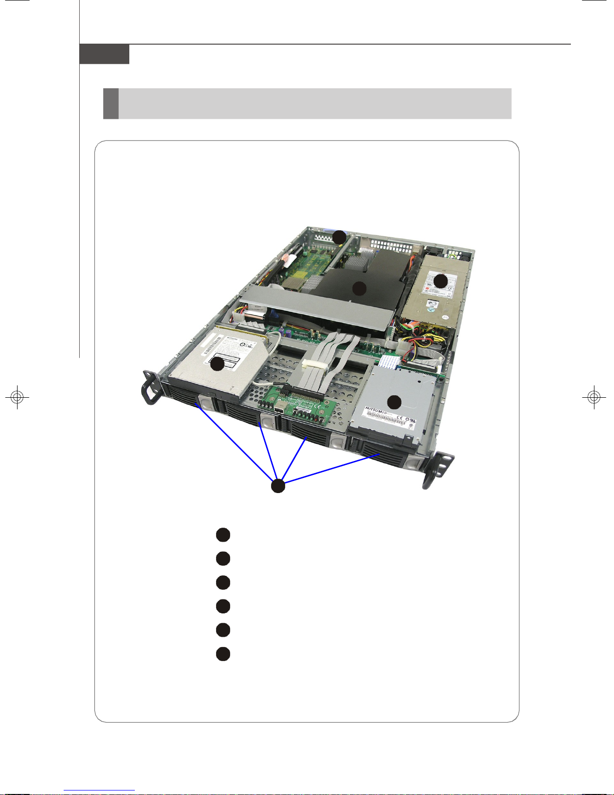
System Overview
Top View
X2-108 SAS Sku and X2-108A4 SATA Sku are available upon request
1-2
1
1
HDD Tray
Slim CD-ROM Drive
Slim Floppy Disk Drive
Fan Duct
PCI-Express Bracket
SSI EPS 1U Power Supply
Page 11
2
3
4
5
8
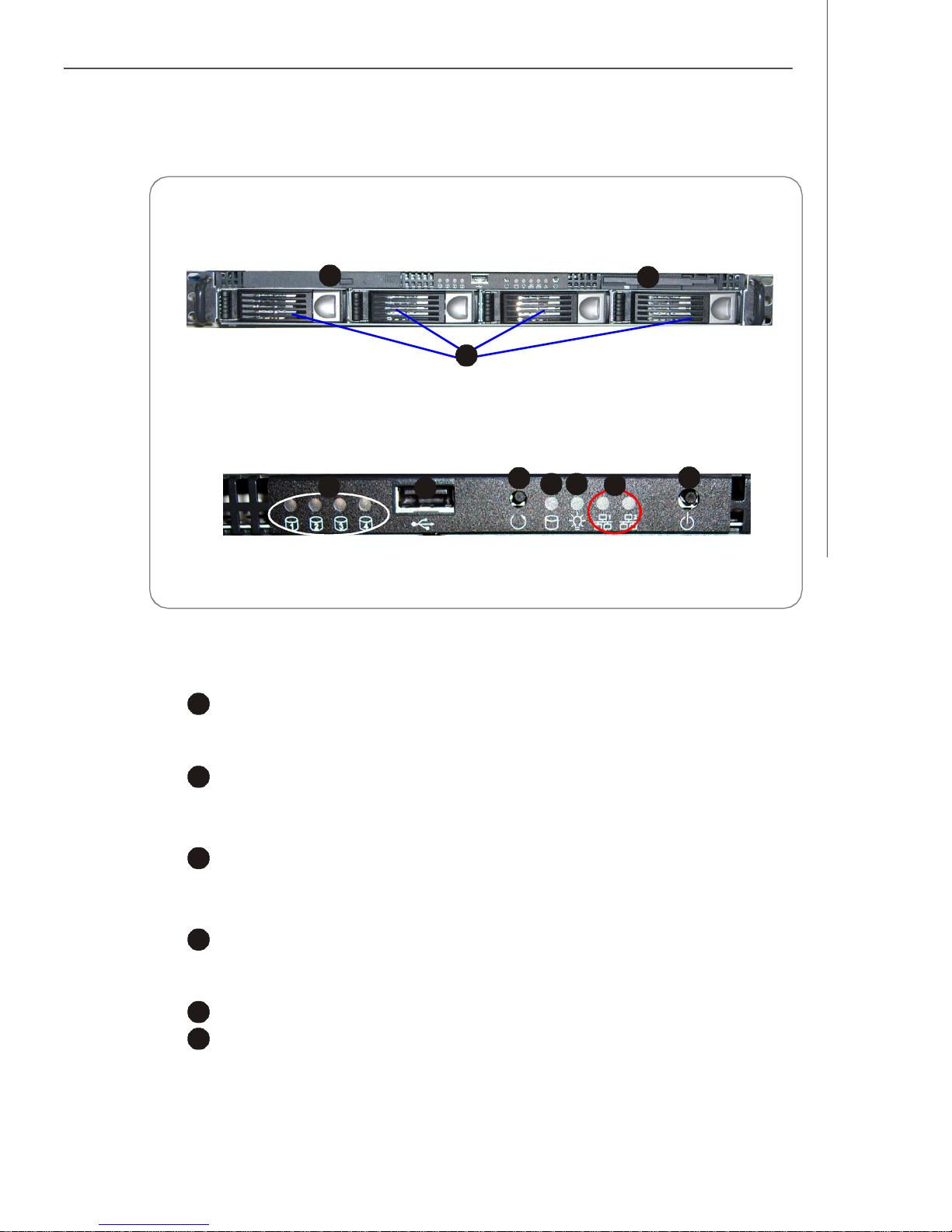
Front View
2137910846
5
Front Bezel
Getting Started
CD-ROM Drive
1
Slim CD-ROM Drive
Floppy Disk Drive
Slim Floppy Disk Drive
HDD Bay
Swappable Hard Disk Drive Bays
Port
USB Port
LED
HDD Power/Status LEDs
HDD Activity LED
This indicator shows the activity status of the hard disk drive. It flashes
when the system is accessing data on the hard disk and remains off when
no disk activity is detected.
1-3
Page 12
MS-9238 Server
9
6
7
Power LED
This indicator shows the power status of the system. It glows when the main
power is turned on.
10
Status LEDs of LAN# 1/2
1. The green LED is on when there is an active connection on the LAN port.
2. This LED flashes when transmitting or receiving activities to or from the
system are detected.
Button
System Reset Button
Power Button
Press this button once to shut down the system, and then once to switch on.
v Front Bezel LEDs
LED Color State Description
Power/Sleep Green On Legacy power on/ACPI S0 state
Red On Sleep/ACPI S1, S4, S5 state
Off Off Power off
HDD Activity Amber Random blink HDD accesss activity
Off Off No disk activity
LAN1/LAN2 Activity Green On LAN link
Green Blink LAN access activity
1-4
Page 13
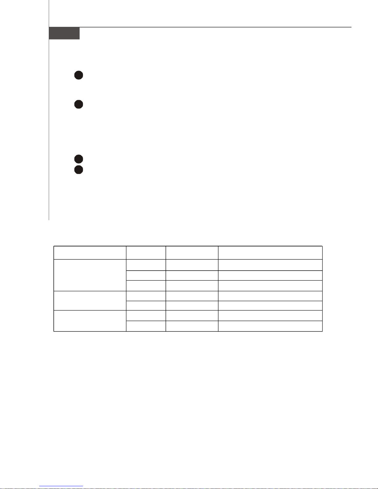
Rear View
2
3
4
5
234
5
Rear Bezel
Getting Started
1
1
PS/2 Keyboard/Mouse Connector
Serial Port
LAN Jacks
v Rear Bezel LEDs
LED Color LED State Condition
RJ45 NIC1 /
NIC2 Link Speed
(Left Side)
RJ45 NIC1 /
NIC2 Access
(Right Side)
Orange On (steady state) LAN link is established.
On (brighter & pulsing) The computer is communicating with another
Green Off 10 Mbit/sec data rate is selected.
Orange On 1000 Mbit/sec data rate is selected.
Off LAN link is not established.
computer on the LAN.
On 100 Mbit/sec data rate is selected.
USB Ports
VGA Port
1-5
Page 14
MS-9238 Server
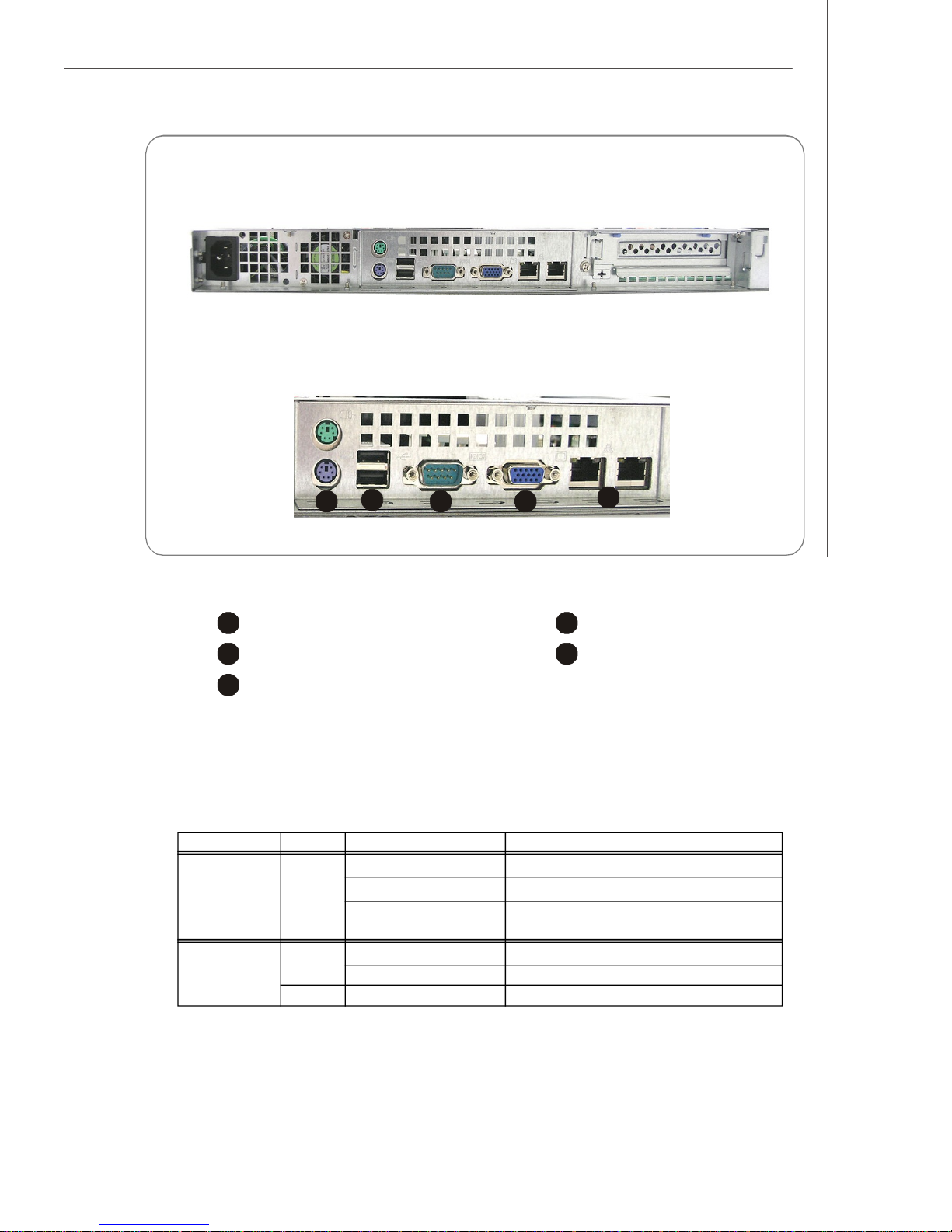
Mouse/Keyboard Connector
Pin6
Mouse Clock
Pin2
Mouse Data
Pin5
Keyboard Clock
Pin1
Keyboard Data
Serial Port
1 2 3 4 5
6 7 8 9
Gigabit LAN Jack
Link Indicator
Pin3 GNDPin4 VCC
PIN SIGNAL DESCRIPTION
1 D0P Differential Pair 0+
2 D0N Differential Pair 03 D1P Differential Pair 1+
4 D2P Differential Pair 2+
5 D2N Differential Pair 26 D1N Differential Pair 17 D3P Differential Pair 3+
8 D3N Differential Pair 3-
Activity Indicator
8 1
VGA Port
USB Port
1 2 3 4
PIN SIGNAL
1 DCD
2 SIN
3 SOUT
4 DTR
5 GND
6 DSR
7 RTS
8 CTS
9 RI
PIN SIGNAL
1 VCC
2 -Data
3 +Data
4 GND
5
15
PIN SIGNAL
1 RED
2 GREEN
3 BLUE
4 N/C
5 GND
6 GND
7 GND
8 GND
9 +5V
10 GND
11 N/C
12 SDA
13 Horizontal Sync
14 Vertical Sync
15 SCL
1
11
1-6
Page 15
Getting Started
Mainboard Specifications
Processor Support
- Supports Intel Xeon processor 5000 series (Harpertown / Wolfdale-
DP / Clovertown / Woodcrest) in Socket LGA771
- Supports Intel Quad-Core / Dual-Core platforms
Supported FSB
- FSB 667/1066/1333MHz
Chipset
- Northbridge: Intel 5000V
- Southbridge: Intel ESB2E
Memory Support
- 6 DDR2 533/667 FB-DIMM (Fully Buffered Dual-In-line DIMM) slots
- Maximum 16GB
LAN
- Supports dual Gigabit Ethernet by Intel 82563EB
SAS (Optional)
- SAS Host Controller: LSI Logic SAS1068
- 4-port controller provides 1.5 and 3Gb/s transfer rates per port
and enables Integrated RAID 0, RAID 1, and RAID 1E solution in
storage environment
SATA
- 4 SATAII ports support 4 SATAII devices
- Storage and data transfers at up to 300 MB/s
IDE
- 1-channel bus master IDE port
- Supports ATA100/66
Floppy
- 1 floppy port
Graphics
- XGI Volari Z7 graphics processor
- 16MB graphics memory
Slots
- 1 PCI-Express x8 slot
1-7
Page 16
MS-9238 Server
Connectors
Back Panel
- 1 x PS/2 mouse & PS/2 keyboard port
- 1 x serial port
- 1 x VGA port
- 2 x USB 2.0 ports
- 2 x individual RJ-45 Gigabit LAN ports
Onboard Pinheaders
- 2 x USB 2.0 pinheaders
- 1 x COM port pinheader
- 1 x front panel pinheader
- 1 x chassis intrusion pinheader
Form Factor
- SSI CEB: 12” X 10.5”
Mounting
- 7 mounting holes
System Management
H8S BMC chip and MSI iConsole AP support IPMI 2.0
BMC Chip
- H8S 200-pin
- Host hardware interface: LPC interface
- Host software interface: KCS interface
l Memory Size
- 256 X 16 Bits SRAM
l Key Features
- IPMI 2.0 compliant
- Out-of-band LAN based management using RMCP
- FRU/SEL access
- Remote out-of-band alerts
- Event log
- Ability to update firmware inband unattended
- Remote access security (MD5)
- Out-of-band environmental monitoring and alerting
- Secure remote power control and system reset over Serial or
shared NIC (RMCP)
- Supports onboard I2C Winbond 83793G & Winbond 83627 to
extend hardware monitor feature
- Supports ASR (Automatic Server Restart)
l System Management
- Three SMBus 2.0 (I2C)
- One SMBus for Intel ESB2E
- One SMBus for IPMB
- One SMBus for Winbond 83793G & Winbond 83627
- CPU fan speed control dependent on system temperature
- System fan speed control dependent on system temperature
l Sensor Management
- Monitored Voltage: 12V, 5V, 3V, VBAT, VTT, Vcore, -12V
1-8
Page 17

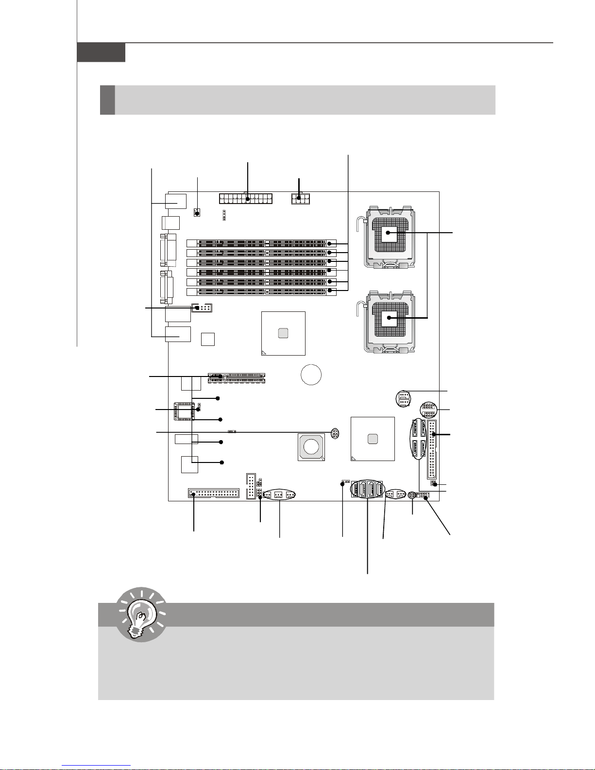
Mainboard Layout
CPUFAN1
CPUFAN2
JRAID2
Getting Started
T: Mouse
B: Keyboard
USB
Ports
COM1
JVGA1
LAN1
LAN 2
I/O Chip
BIOS
XGI
SYSFAN1
COM2
Z7
FDD1
Intel
82563EB
PCIE1
JBIOS1
JPWR2
J8
J13
J12
J11
J9
J14
JPWR1
FBD13
FBD12
FBD11
FBD03
FBD02
FBD01
Intel
5000V
BATT
+
JLANDIS1
JLANDIS2
JBAT1
SYSFAN6
SYSFAN2
SYSFAN5
CPU1
CPU2
JUSB2
JUSB1
Intel
ESB2E
SATA3 SATA1
SATA2 SATA0
SAS5
SAS6
SAS7
SAS8
SYSFAN3
IDE1
SYSFAN4
JFP1
JSTATE1
JACT1
JCI1
JRST1
JACT2
5000V Master2 (MS-9638 v3.X) SSI CEB Server Board
1-9
Page 18

MS-9238 Server
1-10
Page 19
Hardware Setup
Chapter 2
Hardware Setup
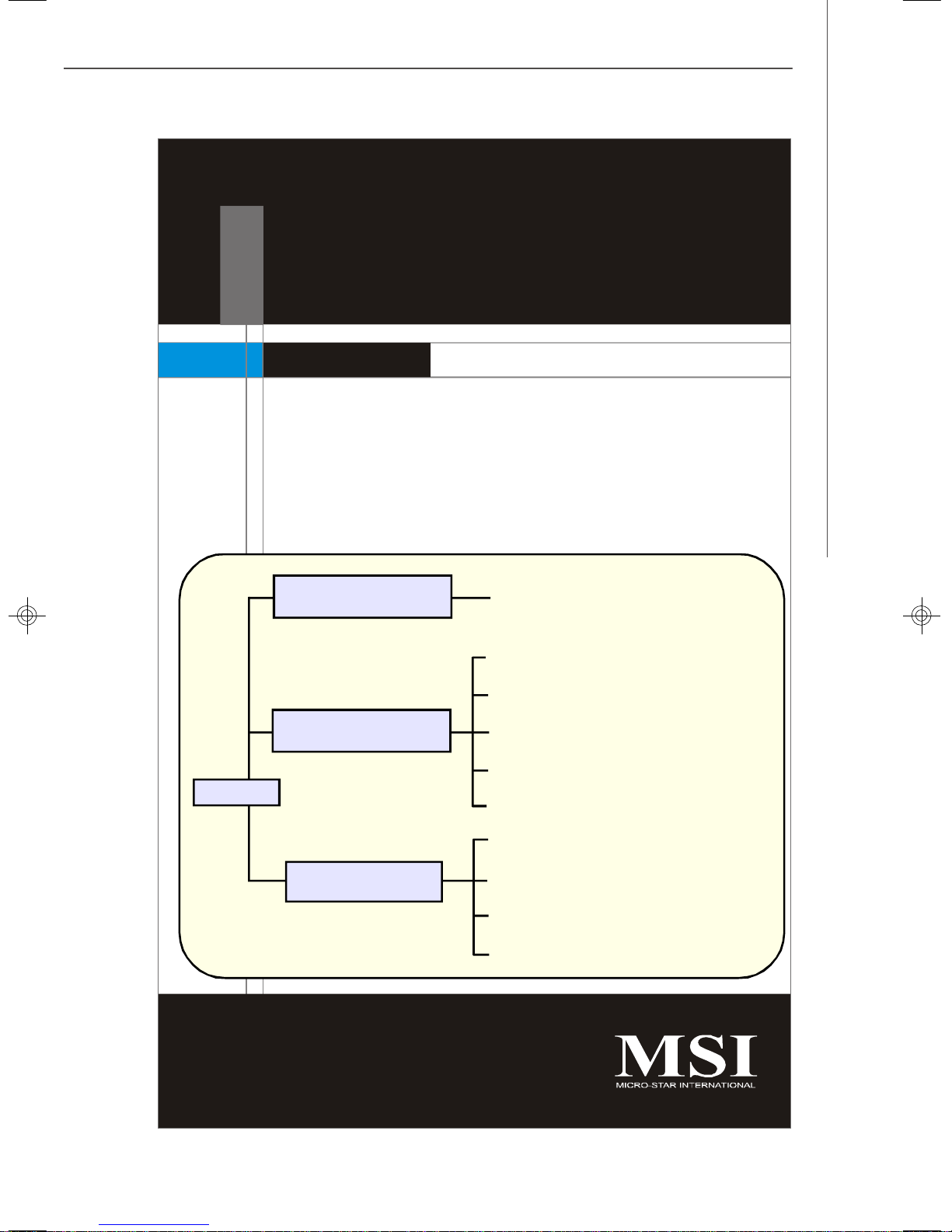
Refer to the system assembly flowchart and the chart
below to determine the proper sequence of removing
or installing components to the server.
MS-9238
Mainboard Hardware
System Assembly
Rack Mounting
CPU, Memory, Power Supply, Back
Panel, Connectors, Jumpers, Slot
Chassis Cover
CPU, Heatsink
Memory
Riser Card
Hard Disk Drives
Chassis Ears and Rails
Rack Rails
Chassis into the Rack
Chassis off the Rack
2-1
Page 20
MS-9238 Server
Quick Components Guide
Back Panel
I/O, p.2-7
COM2,
p.2-12
PCI-Class
Slots, p.2-15
JBIOS1, p.2-14
JLANDIS1/2,
p.2-14
SYSFAN1,
p.2-10
BIOS
JBIOS1
JPWR2, p.2-6
DDR2 DIMMs, p.2-4
JPWR1, p.2-6
CPU, p.2-3
CPUFAN1/2,
p.2-10
JUSB1/2,
p.2-12
IDE1,
p.2-8
FDD1, p.2-8
Important
CAUTION!!! Please note that the CPU1/CPU2 VRM & memory/south bridge
area should be respectively kept under 105oC and 85oC. To ensure system
stability, always protect the system with proper cooling. Otherwise, overheating may damage the system.
2-2
J9, p.2-14
SYSFAN5/6/2,
p.2-10
JBAT1,
p.2-13
SAS5~8, p.2-9
SYSFAN3/4,
p.2-10
JCI1, p.2-10
SATA0~3,
p.2-9
JACT2/1,
p.2-11
JFP1, p.2-11
Page 21
Hardware Setup
CPU (Central Processing Unit)
This mainboard supports the latest Intel® Xeon® processor 5000 series
(Harpertown/Wolfdale-DP/Clovertown/Woodcrest) in Socket LGA771. When
you are installing the CPU, make sure that you install the cooler to prevent the CPU
from overheating. If you do not have a CPU cooler, contact your dealer to purchase
and install them before turning on the computer.
Important
1. Overheating will seriously damage the CPU and system. Always make
sure the cooling fan can work properly to protect the CPU from overheating.
2. Make sure that you apply an even layer of heat sink paste (or thermal tape)
between the CPU and the heatsink to enhance heat dissipation.
3. While replacing the CPU, always turn off the power supply or unplug the
power supply’s power cord from the grounded outlet first to ensure the
safety of CPU.
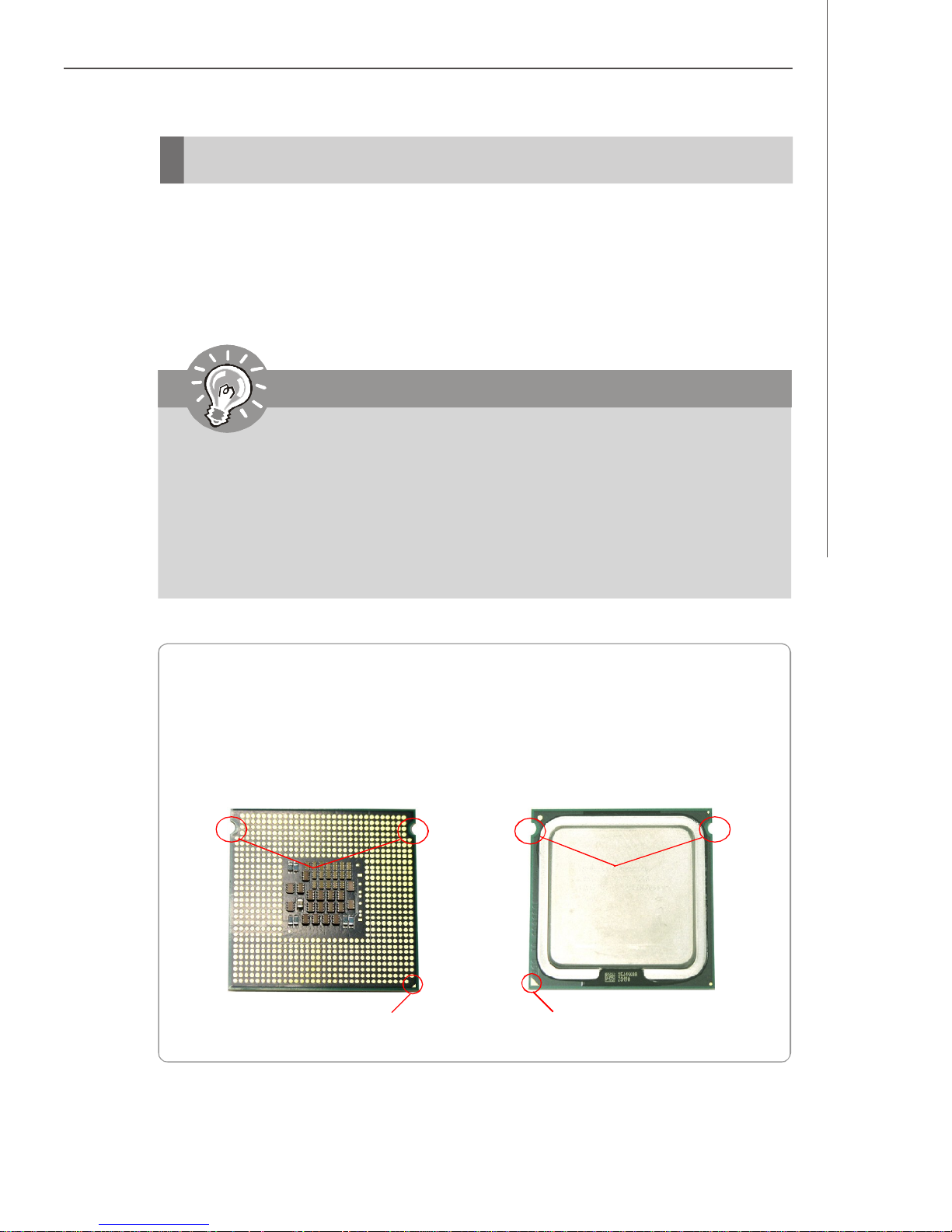
Introduction to LGA 771 CPU
The pin-pad side of LGA 771 CPU.
Alignment Key
Yellow triangle is the Pin 1 indicator
The surface of LGA 771 CPU.
Remember to apply some silicone
heat transfer compound on it for
better heat dispersion.
Alignment Key
Yellow triangle is the Pin 1 indicator
2-3
Page 22
MS-9238 Server
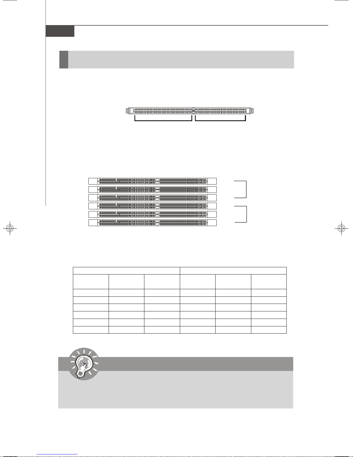
Memory
The mainboard provides six 240-pin 533/667MHz ECC DDR2 FB-DIMM slots to support the maximum of 16GB memory capacity.
DDR2
240-pin, 1.8V
64x2=128 pin 56x2=112 pin
Memory Population Rules
FBD13
FBD12
FBD11
FBD03
FBD02
FBD01
Channel 1
Channel 0
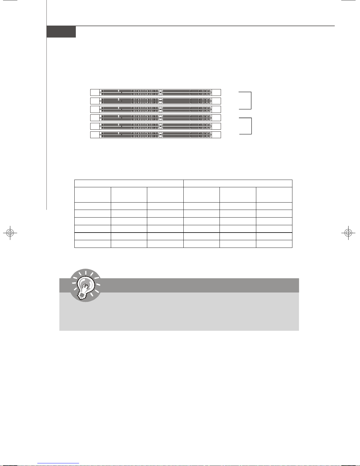
Check the numbers of your DIMM modules and follow the population rules to install the
memory.
Channel 0 Channel 1
1st DIMM
(FBD01)
V
V V
V V V
V V
V V V V
V V V V V V
2nd DIMM
(FBD02)
3rd DIMM
(FBD03)
1st DIMM
(FBD11)
2nd DIMM
(FBD12)
3rd DIMM
(FBD13)
Important
1. To enable successful system boot-up, always insert the memory modules
into the FBD01 first (Channel 0/ 1st).
2. In dual-channel mode, DIMM modules must be of the same type and density.
2-4
Page 23

Hardware Setup
Installing Memory Modules
1. The memory module has only one notch on the center and will only fit in the right
orientation.
2. Insert the memory module vertically into the DIMM slot. Then push it in until the
golden finger on the memory module is deeply inserted in the DIMM slot.
Important
You can barely see the golden finger if the memory module is properly inserted
in the DIMM slot.
3. The plastic clip at each side of the DIMM slot will automatically close.
Volt
Notch
2-5
Page 24
MS-9238 Server
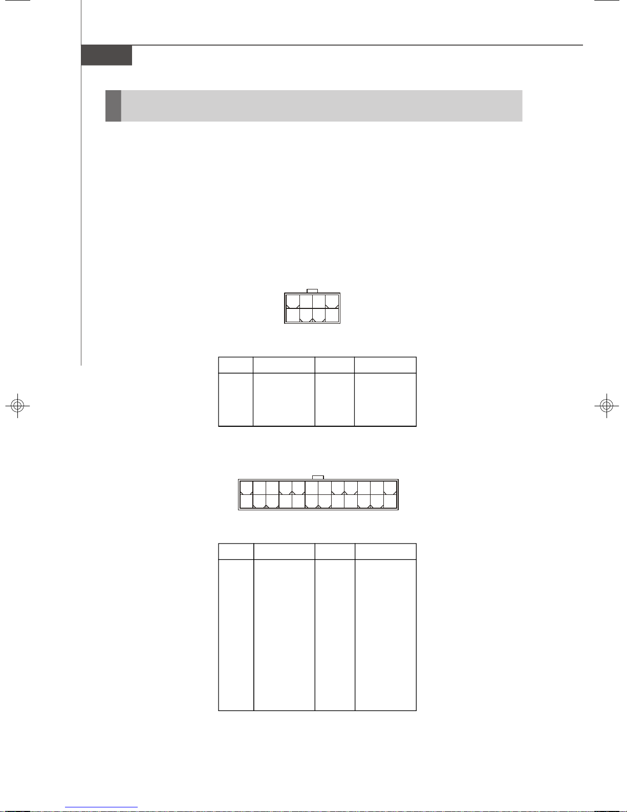
Power Supply
SSI 8-Pin CPU Power Connector: JPWR1
This connector provides 12V power output to the CPUs.
SSI 24-Pin System Power Connector: JPWR2
This connector allows you to connect to an SSI power supply. To connect to the SSI
power supply, make sure the plug of the power supply is inserted in the proper
orientation and the pins are aligned. Then push down the power supply firmly into the
connector.
JPWR1
8 5
4
JPWR1 Pin Definition
1
PIN SIGNAL
1 GND
2 GND
3 GND
4 GND
24
12
JPWR2 Pin Definition
PIN SIGNAL
1 +3.3V
2 +3.3V
3 GND
4 +5V
5 GND
6 +5V
7 GND
8 PWR OK
9 5VSB
10 +12V
11 +12V
12 +3.3V
PIN SIGNAL
5 +12V
6 +12V
7 +12V
8 +12V
JPWR2
13
1
PIN SIGNAL
13 +3.3V
14 -12V
15 GND
16 PS-ON#
17 GND
18 GND
19 GND
20 Res
21 +5V
22 +5V
23 +5V
24 GND
2-6
Page 25
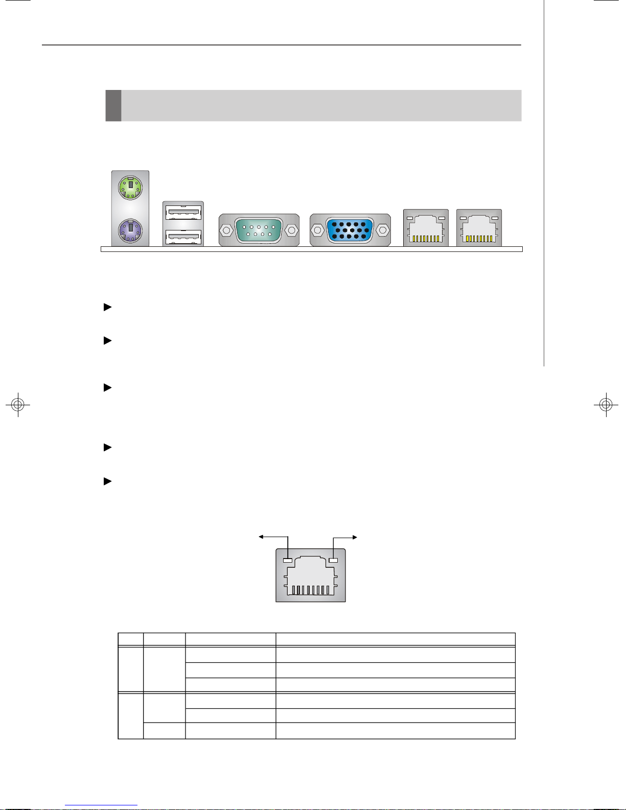
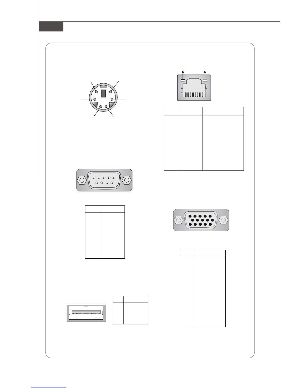
Back Panel
Mouse
USB Ports
Hardware Setup
Keyboard
VGA PortSerial Port LAN LAN
Mouse/Keyboard Connector
The standard PS/2® mouse/keyboard DIN connector is for a PS/2® mouse/keyboard.
USB Ports
The Universal Serial Bus root is for attaching USB devices such as keyboard, mouse,
or other USB-compatible devices.
Serial Port
The serial port is a 16550A high speed communications port that sends/ receives 16
bytes FIFOs. You can attach a serial mouse or other serial devices directly to the
connector.
VGA Port
The DB15-pin female connector is provided for monitors.
RJ-45 LAN Jack
The standard RJ-45 jack is for connection to Local Area Network (LAN). You can
connect a network cable to it.
Link Indicator
Activity Indicator
LED Color LED State Condition
Off LAN link is not established.
Left Orange On (steady state) LAN link is established.
On (brighter & pulsing)The computer is communicating with another computer on the LAN.
Green Off 10 Mbit/sec data rate is selected.
Right On 100 Mbit/sec data rate is selected.
Orange On 1000 Mbit/sec data rate is selected.
RJ-45 LAN Jack
2-7
Page 26
MS-9238 Server
Connectors
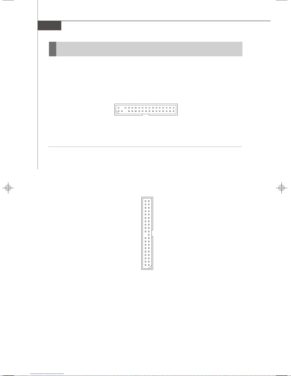
Floppy Disk Drive Connector: FDD1
The mainboard provides a standard floppy disk drive connector.
FDD1
ATA100 Hard Disk Connector: IDE1
The mainboard has a 32-bit Enhanced PCI IDE and Ultra DMA 66/100 controller that
provides PIO mode 0~4, Bus Master, and Ultra DMA 66/100 function. You can connect
hard disk drives, CD-ROM and other IDE devices.
2-8
IDE1
Page 27
Hardware Setup
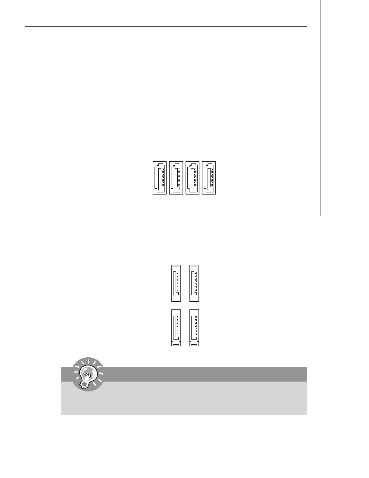
Serial Attached SCSI Connector: SAS5 ~ SAS8 (Optional)
The SAS connector is a new generation serial communication protocol for devices
designed to allow for much higher speed data transfers. It supports data transfer
speeds up to 3 Gbit/s. SAS uses serial communication instead of the parallel method
found in traditional SCSI devices but still uses SCSI commands for interacting with
SAS devices. Each SAS connector can connect to 1 disk drive.
SAS6
SAS5
SAS7
SAS8
Serial ATA Connector: SATA0 ~ SATA3 (Optional)
SATA0 ~ SATA3 are high-speed SATA II interface ports and support SATA II data rates
of 300MB/s. Each SATA II connector can connect to 1 hard disk device and is fully
compliant with Serial ATA 2.0 specifications.
SATA1
SATA3
SATA0
SATA2
Important
Please do not fold the SATA/SAS accessory cable into 90-degree angle.
Otherwise, data loss may occur during transmission.
2-9
Page 28

MS-9238 Server
Chassis Intrusion Switch Connector: JCI1
This connector connects to a 2-pin chassis switch. If the chassis is opened, the
switch will be short. The system will record this status and show a warning message on the screen. To clear the warning, you must enter the BIOS utility and clear the
record.
CINTRU
GND
1
2
JCI1
Fan Power Connectors: CPUFAN 1/2, SYSFAN 1/2/3/4/5/6
The fan power connectors support system cooling fan with +12V. When connecting
the wire to the connectors, always take note that the red wire is the positive and
should be connected to the +12V, the black wire is Ground and should be connected
to GND. If the mainboard has a System Hardware Monitor chipset onboard, you must
use a specially designed fan with speed sensor to take advantage of the CPU fan
control.
C
S
O
E
N
N
T
+
S
G
R
1
O
N
O
2
R
D
V
L
GND
+12V
SENSOR
+12V
SENSOR
GND
CPUFAN1/2
Important
Please refer to the recommended CPU fans at Intel® official website or consult
the vendors for proper CPU cooling fan.
2-10
SYSFAN1
SYSFAN 2/3/4/5/6
Page 29
Hardware Setup
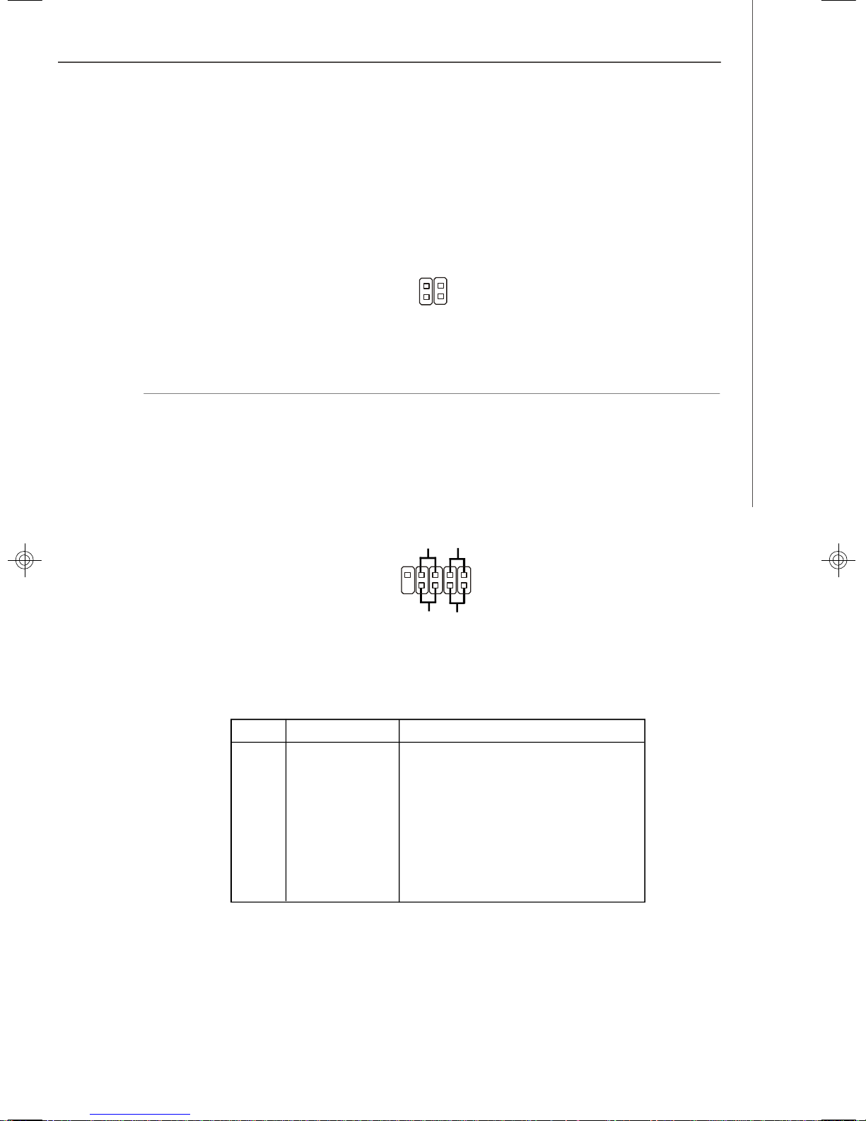
LAN LED Connectors: JACT1, JACT2
The LAN LED connectors are used to connect to LAN LEDs, which show the activity
of the LAN. The JACT1 is for the LAN 1 jack and the JACT2 is for the LAN2 jack. Both
LAN1 & LAN2 jacks are located on the back panel.
+ +
JACT2
JACT1
- -
Front Panel Connector: JFP1
The mainboard provides one front panel connector for electrical connection to the
front panel switches and LEDs. The JFP1 is compliant with Intel® Front Panel I/O
Connectivity Design Guide.
HDD
LED
-
-
+
+
1
2
-
+
Power
LED
JFP1
Reset
Switch
9
10
Power
Switch
JFP1 Pin Definition
PIN SIGNAL DESCRIPTION
1 HD_LED + Hard disk LED pull-up
2 FP PWR/SLP MSG LED pull-up
3 HD_LED - Hard disk active LED
4 FP PWR/SLP MSG LED pull-up
5 RST_SW - Reset Switch low reference pull-down to GND
6 PWR_SW + Power Switch high reference pull-up
7 RST_SW + Reset Switch high reference pull-up
8 PWR_SW - Power Switch low reference pull-down to GND
9 RSVD_DNU Reserved. Do not use.
2-11
Page 30
MS-9238 Server
Serial Port Connector: COM 2
The mainboard provides one 9-pin header as serial port. The port is a 16550A high
speed communications port that sends/receives 16 bytes FIFOs. You can attach a
serial mouse or other serial devices directly to it.
Pin Definition
PIN SIGNAL DESCRIPTION
19
10
2
COM2
1 DCD Data Carry Detect
2 SIN Serial In or Receive Data
3 SOUT Serial Out or Transmit Data
4 DTR Data Terminal Ready
5 GND Ground
6 DSR Data Set Ready
7 RTS Request To Send
8 CTS Clear To Send
9 RI Ring Indicate
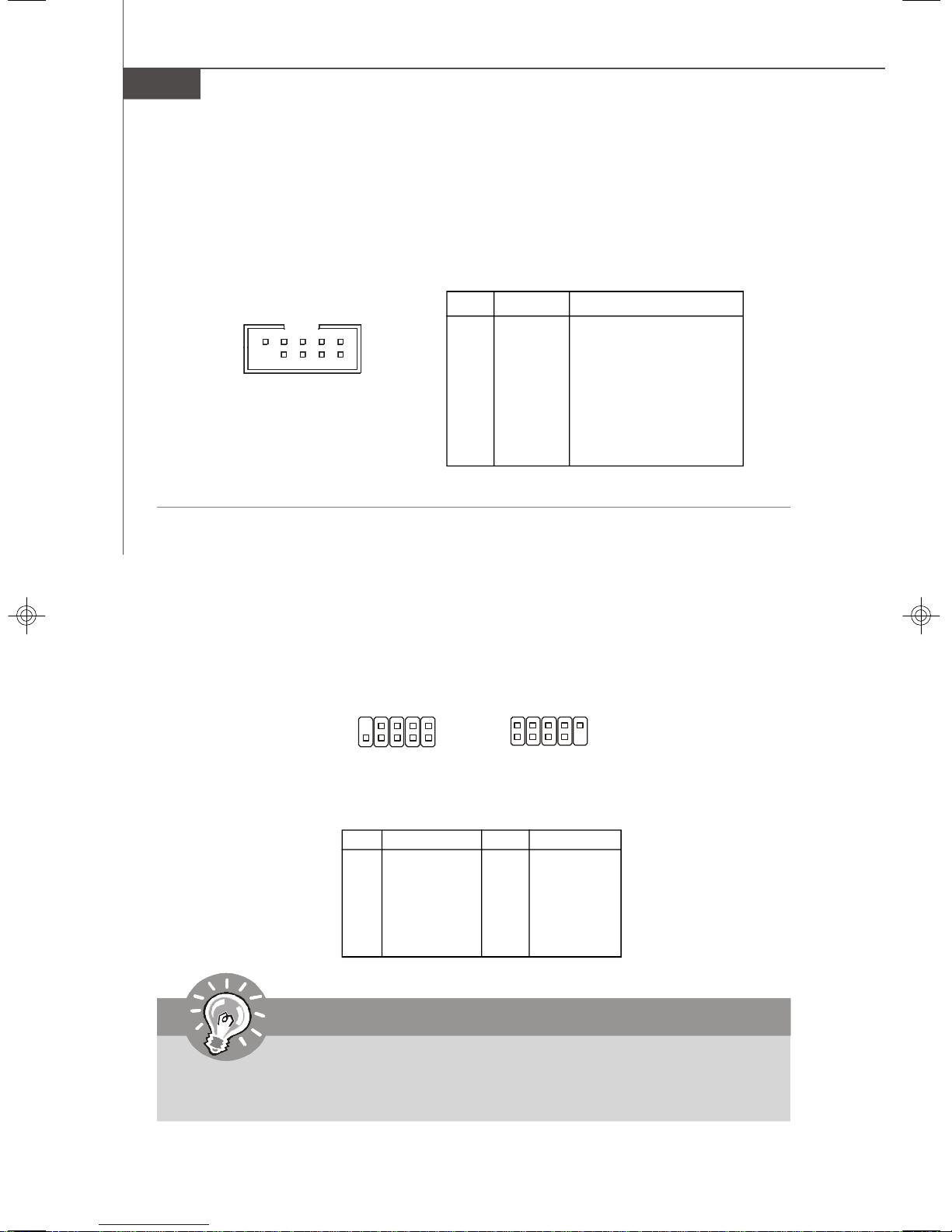
Front USB Connector: JUSB1, JUSB2
The mainboard provides two USB 2.0 pinheaders (optional USB 2.0 bracket available)
that are compliant with Intel® I/O Connectivity Design Guide. USB 2.0 technology
increases data transfer rate up to a maximum throughput of 480Mbps, which is 40
times faster than USB 1.1, and is ideal for connecting high-speed USB interface
peripherals such as USB HDD, digital cameras, MP3 players, printers, mo-
dems and the like.
9
10
JUSB1
1
2
2
1
JUSB2
Pin Definition
PIN SIGNAL PIN SIGNAL
1 VCC 2 VCC
3 USB0- 4 USB15 USB0+ 6 USB1+
7 GND 8 GND
9 Key (no pin) 10 NC
10
9
Important
Note that the pins of VCC and GND must be connected correctly to avoid
possible damage.
2-12
Page 31

Hardware Setup
Jumpers
Clear CMOS Jumper: JBAT1
There is a CMOS RAM onboard that has a power supply from external battery to keep
the data of system configuration. With the CMOS RAM, the system can automatically
boot OS every time it is turned on. If you want to clear the system configuration, set
the JBAT1 (Clear CMOS Jumper ) to clear data.
JBAT1
3
1
Keep Data Clear Data
3
1
1
Important
To clear CMOS you should:
1. Short 1-2 pin while the system is off. Restart the PC and press F2 to enter
the BIOS Setup Utility. Shut down the PC.
2. Short 2-3 pin while the system is off. Restart the PC and press F2 to enter
the BIOS Setup Utility. Shut down the PC.
3. Short 1-2 pin while the system is off. Restart the PC.
Avoid clearing the CMOS while the system is on; it will damage the mainboard.
2-13
Page 32

MS-9238 Server
BIOS Recovery Jumper: J9
Users can short connect pin#2-3 to recover the system BIOS. When the system is
done with the job, the buzzer will beep to remind users to set the jumper to its normal
state (pin#1-2 short connected).
3
1
J9
3
1
1
RecoveryNormal
BIOS Write Protect Jumper: JBIOS1
A "boot block" program is included as part of the system BIOS to recover the system
from a situation when the BIOS code is incorrect/corrupted or needs to be updated.
When the BIOS code is corrupted or needs to be updated, you have to at first disable
the write protect function by shorting 1-2 pin of the JBIOS1 jumper. Then the boot
block will try to recover the BIOS code, usually by reading it from a specially-prepared floppy disk.
Under normal operation, we suggest that you enable the write protect function by
shorting 2-3 pin of the JBIOS1 jumper to protect the boot block from virus infection.
1
3
1
JBIOS1
1
3
Disable Write Protect Enable Write Protect
LAN Jumper: JLANDIS1, JLANDIS2
These jumpers control the onboard LAN. The JLANDIS1 disables/enables the LAN1
jack while the JLANDIS2 disables/enables the LAN2 jack.
JLANDIS1/
JLANDIS2
2-14
3
1
1
Enable LAN1/
Enable LAN2
Disable LAN1/
Disable LAN2
3
1
Page 33

Hardware Setup
Slots
PCI (Peripheral Component Interconnect) Express Slot
The PCI Express slot supports the PCI Express interface expansion card.
The PCI Express x 8 slot supports up to 2.0 GB/s transfer rate.
PCI Express x8 Slot
Important
When adding or removing expansion cards, make sure that you unplug the
power supply first. Meanwhile, read the documentation for the expansion card
to configure any necessary hardware or software settings for the expansion
card, such as jumpers, switches or BIOS configuration.
2-15
Page 34

MS-9238 Server
START
System Assembly Flowchart
The following flowchart shows basic system assembly procedures. Please note
that always wear anti-static gloves when handling electrical components and exercise caution during the installation process. For more information, contact your local
dealer or experienced technician.
REMOVE CHASSIS COVER
INSTALL
CPU & HEATSINK
INSTALL
MEMORY MODULES
REMOVE
RISER CARD BRACKET
INSTALL
2-16
RISER CARDS
Page 35

REPLACE
RISER CARD BRACKET
INSTALL
HARD DISK DRIVES
Hardware Setup
CONNECT HDD
& POWER CORDS
CHECK IF ALL PARTS
ARE PROPERLY CONNECTED
REPLACE
CHASSIS COVER
FINISH
2-17
Page 36

MS-9238 Server
System Assembly
Removing the Chassis Cover
1. Unscrew the chassis cover.
2. Press the release buttons and slide the chassis cover forwards.
3. Lift up the cover and remove it from
the chassis.
2-18
Page 37

Replacing the Chassis Cover
1. Replace the chassis cover and slide it backwards.
Hardware Setup
2. Screw to secure the chassis cover.
Important
Before you remove or install any components, make sure the server is not
turned on or connected to the AC power.
2-19
Page 38

MS-9238 Server
CPU, Heatsink, and Fan Duct
1. On top of the CPU is a fan duct designed to enhance heat dissipation of the CPU.
Lift up & remove the fan duct before installing the CPU.
2. Locate the first CPU socket. (The CPU has a plastic cap on it to protect the contact
from damage. Before installing the CPU, always cover it to protect the socket
pins.)
3. Remove the plastic cap from the load plate. The pins of the socket reveal.
CPU2
CPU1
4. Raise the load lever up to its full extent.5. Open the load plate.
2-20
Page 39

6. After confirming the CPU direction (indicated below with red circles) for correct mating, put down
the CPU in the socket housing frame. Be sure to
grasp on the edge of the CPU base. Note that the
alignment keys are matched.
7. Visually inspect if the CPU is seated well into the
socket. If not, take out the CPU with pure vertical
motion and reinstall.
Hardware Setup
Alignment Key
Yellow triangle is the Pin 1 indicator
8. Cover the load plate onto the package.
9. Press down the load lever lightly onto the load plate and then secure the lever
with the hook under the retention tab.
10.Follow the same procedures to install
the second CPU.
Note: To install DUAL CPUs
on the board, you must use
the same types of CPUs
running at the same FSB
frequency.
2-21
Page 40

MS-9238 Server
11.Place the heat sink on top of CPU1 and secure the screws on both sides.
Note: The heat sink has to be installed to prevent the CPU from overheating.
12.Follow the same procedures to install the second heatsink.
2-22
Page 41

Hardware Setup
Memory
1. Locate the DIMM slots on the mainboard. Insert the memory module vertically into
the DIMM slot. Then push it in until the golden finger on the memory module is
deeply inserted in the DIMM slot. The plastic clip at each side of the DIMM slot will
automatically close.
2. Follow the same procedures to install more memory modules if necessary.
3. Replace the fan duct on top of the
heatsinks and the memory DIMMs.
Note: To ensure proper cooling,
make sure the heatsinks & the fan
duct are properly installed.
2-23
Page 42
MS-9238 Server
Memory Population Rules
FBD13
FBD12
FBD11
FBD03
FBD02
FBD01
Channel 1
Channel 0
Check the numbers of your DIMM modules and follow the population rules to install the
memory.
Channel 0 Channel 1
1st DIMM
(FBD01)
V
V V
V V V
V V
V V V V
V V V V V V
2nd DIMM
(FBD02)
3rd DIMM
(FBD03)
1st DIMM
(FBD11)
2nd DIMM
(FBD12)
3rd DIMM
(FBD13)
Important
1. To enable successful system boot-up, always insert the memory modules
into the FBD01 first (Channel 0/ 1st).
2. In dual-channel mode, DIMM modules must be of the same type and density.
2-24
Page 43

Hardware Setup
Expansion Card
1. Locate the riser card bracket and lift it up from the chassis.
2. Unscrew the cover plate and put it aside for later use.
2-25
Page 44
MS-9238 Server
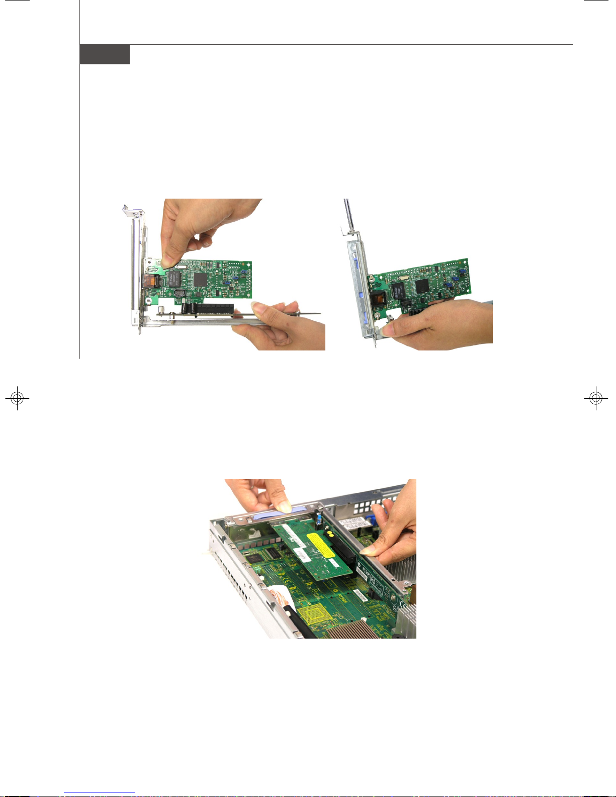
3. Insert the expansion card into the PCI-Express slot on the riser card.
4. Screw to secure the expansion card bracket.
5. Place the riser card bracket on top of the PCI-Express slot on the motherboard.
Align the riser card golden fingers with the PCI-Express slot.
6. Push the riser card bracket carefully down with even force on both sides.
2-26
Page 45

Hardware Setup
Hard Disk Drive
1. To release the hot-swapping HDD tray, flip open the tray lever and pull the tray
out of the bay.
2. At the rear of the HDD are four screw holes, two on the right and two on the left
side. At the back of the HDD rack are four identical screw holes as on the HDD.
Place the HDD into the rack and align the screw holes on the HDD with the ones
on the rack. Secure the HDD with four screws supplied by the HDD vendor.
2-27
Page 46

MS-9238 Server
3. Insert the HDD tray into the bay and
push the tray lever back in place.
2-28
Page 47

Rack Mounting
1. Pull the inner channel out.
latch
Press the latch to
disconnect.
Hardware Setup
2. Assemble the inner rail to the chassis.
Fasten 6 screws at least to attach the inner channel onto the chassis.
M4 screw
2-29
Page 48

MS-9238 Server
3. Mount the L-shaped bracket onto the outer channel.
FRONT
Use black round head
screws.
4. Mount the slides to the vertical racks.
Type A
Type B
BACK
shall be in flush position
washer
black screw
2-30
M4 screw
M5 screw
Type C
M5 screw
Page 49

5. Insert the chassis into the frame.
Hardware Setup
2-31
Page 50

MS-9238 Server
2-32
Page 51

Chapter 3
BIOS Setup
This chapter provides information on the BIOS Setup
program and allows you to configure the system for
optimum use.
You may need to run the Setup program when:
BIOS Setup
² An error message appears on the screen during the
system booting up, and requests you to run SETUP.
² You want to change the default settings for cus-
tomized features.
3-1
Page 52

MS-9238 Server
Entering Setup
Power on the computer and the system will start POST (Power On Self Test) process.
When the message below appears on the screen, press <F2> key to enter Setup.
Press <F2> to enter SETUP
If the message disappears before you respond and you still wish to enter Setup,
restart the system by turning it OFF and On or pressing the RESET button. You may
also restart the system by simultaneously pressing <Ctrl>, <Alt>, and <Delete> keys.
Important
1.The items under each BIOS category described in this chapter are under
continuous update for better system performance. Therefore, the description may be slightly different from the latest BIOS and should be held for
reference only.
2.Upon boot-up, the 1st line appearing after the memory count is the BIOS
version. It is usually in the format:
P9238IMS V3.1 061007 where:
1st digit refers to BIOS maker as A = AMI, W = AWARD, and P =
PHOENIX.
2nd - 5th digit refers to the model number.
6th digit refers to the chipset as I = Intel, N = nVidia, and V = VIA.
7th - 8th digit refers to the customer as MS = all standard customers.
V3.1 refers to the BIOS version.
061007 refers to the date this BIOS was released.
3-2
Page 53

Control Keys
BIOS Setup
↑ ↓ Select Items
← Select Menus
Enter Select Sub-menus
Esc Exit
-/+ Change Values
F1 Help
<F9> Setup Defaults
<F10> Save and Exit
Getting Help
After entering the Setup menu, the first menu you will see is the Main Menu.
Main Menu
The main menu lists the setup functions you can make changes to. You can use the
arrow keys ( ↑↓ ) to select the item. The on-line description of the highlighted setup
function is displayed at the bottom of the screen.
Sub-Menu
If you find a right pointer symbol (as shown in the right view)
appears to the left of certain fields that means a sub-menu can
be launched from this field. A sub-menu contains additional options for a field parameter. You can use arrow keys ( ↑↓ ) to
highlight the field and press <Enter> to call up the sub-menu.
Then you can use the control keys to enter values and move
from field to field within a sub-menu. If you want to return to the main menu, just press
the <Esc >.
General Help <F1>
The BIOS setup program provides a General Help screen. You can call up this screen
from any menu by simply pressing <F1>. The Help screen lists the appropriate keys
to use and the possible selections for the highlighted item. Press <Esc> to exit the
Help screen.
3-3
Page 54

MS-9238 Server
The Menu Bar
Main
Use this menu for basic system configurations, such as time, date etc.
Advanced
Use this menu to set up the items of special enhanced features available on your
system’s chipset.
Security
Use this menu to set Supervisor and User Passwords.
Power
Use this menu to specify your settings for power management.
Boot
Use this menu to specify the priority of boot devices.
Exit
This menu allows you to load the BIOS default values or factory default settings into
the BIOS and exit the BIOS setup utility with or without changes.
3-4
Page 55

Main
BIOS Setup
System Time (hh:mm:ss)
The time format is <Hour> <Minute> <Second>.
System Date (mm:dd:yy)
The date format is <Month> <Date> <Year>.
Legacy Diskette A
This setting allows you to set the type of floppy drives installed.
IDE Channel 0 Master/Slave, SATA Port 1/2/3/4
[Type] Press <+> or <-> to select [Manual], [None] or
[Auto] type. Note that the specifications of
your drive must match with the drive table.
The hard disk will not work properly if you
enter improper information for this category.
If your hard disk drive type is not matched or
listed, you can use [Manual] to define your
own drive type manually.
[Multi-Sector Transfers] Any selection except Disabled determines
the number of sectors transferred per block
[LBA Mode Control] Enabling LBA causes Logical Block Ad-
dressing to be used in place of Cylinders,
Heads and Sectors
3-5
Page 56

MS-9238 Server
[32-Bit I/O] Enables 32-bit communication between
CPU and IDE card
[Tranfer Mode] Selects the method for transferring the data
between the hard disk and system memory
[Ultra DMA Mode] Indicates the type of Ultra DMA
Boot Features
The sub-menu is used to configure system boot-up features.
Floppy Check
This setting causes the BIOS to search for floppy disk drives at boot time. When
enabled, the BIOS will activate the floppy disk drives during the boot process.
The drive activity light will come on and the head will move back and forth once.
Summary Screen
Selecting [Enabled] displays system summary screen during boot up.
QuickBoot Mode
Setting the item to [Enabled] allows the system to boot within 20 seconds since
it will skip some check items.
3-6
Page 57

System Information
Press <Enter> to view the hardware specifications of your system.
BIOS Setup
System Memory, Extended Memory
These items show the memory status of the system. (Read-only)
3-7
Page 58

MS-9238 Server
Advanced
Reset Configuration Data
Select [Yes] if you want to clear the Extended System configuration Data (ESCD)
area.
Large Disk Access Mode
Defaulting this setting to [DOS] will create a Translated FDPT. Compatible ill-behaved
applications will operate correctly when [DOS] is selected. Setting to [Other] will
create a Standard FDPT. Incompatible ill-behaved applications will function correctly
with [Other].
3-8
Page 59

Advanced Chipset Control
BIOS Setup
USB Host Controller
This setting disables/enables the onboard USB host controller.
IOAT Support
This field enables Intel I/O Acceleration Technology which transfers data more
efficiently.
ECC Function Support
This setting supports Single bit / None ECC (Error Correction Code) checking, a
method of checking the integrity of data in DRAM.
Memory Branch Mode
This setting determines the memory branch mode. Setting to [Sequential] or
[Interleave] depending on your needs.
Parallel ATAA
This setting allows you to enable or disable the onchip Parallel-ATA controller.
Serial ATAA
This setting allows you to enable or disable the onchip Serial-ATA controller.
SATA Controller Mode Option
This setting specifies SATA controller mode. Please note that Pre-Win2K
OS’s do not work in Enhanced mode.
[Compatible] SATA and PATA drives are auto-detected and placed
in Legacy mode.
3-9
Page 60

MS-9238 Server
[Enhanced] SATA and PATA drives are auto-detected and placed
(non-AHCI) in Native IDE mode.
SATA RAID & AHCI Enable (for Adaptec SATA RAID Option ROM)
If this setting is set to [Enabled] and the SATA RAID function is not configured,
only AHCI mode will be supported. Once AHCI mode is enabled, 6 SATA
HDDs will be supported under this mode.
3-10
Page 61

Advanced Processor Options
BIOS Setup
Intel Virtualization Technology
Virtualization enhanced by Intel Virtualization Technology will allow a platform
to run multiple operating systems and applications in independent partitions.
With virtualization, one computer system can function as multiple “virtual” systems.
Thermal Management 2 (auto detect function)
This setting specifies the thermal technologies implemented in the Intel® processor.
Execute Disable Bit
Intel's Execute Disable Bit functionality can prevent certain classes of malicious
"buffer overflow" attacks when combined with a supporting operating system.
This functionality allows the processor to classify areas in memory by where
application code can execute and where it cannot. When a malicious worm
attempts to insert code in the buffer, the processor disables code execution,
preventing damage or worm propagation.
Discrete MTRR Allocation
If the system has 4GB of memory or greater, Discrete MTRR Allocation must be
enabled in the BIOS Memory Cache section. Otherwise, system performance
will be affected.
Processor Power Management
This setting offers power management options for the processor.
[Disabled] C States and GV1/GV3 are disabled.
[GV1/GV3 Only] C States are disabled.
[C States Only] GV1/GV3 are disabled.
[Enabled] C States and GV1/GV3 are enabled.
3-11
Page 62

MS-9238 Server
I/O Device Configuration
Serial Port A/B
This is used to enable or disable the onboard serial port A/B.
Base I/O Address
These items specify the base I/O addresses of the onboard serial port A/B.
Interrupt
These field allows you to select IRQ Resources for serial port A/B.
Floppy Disk Controller
Select [Enabled] if your system has a floppy disk controller (FDC) installed on
the system board and you wish to use it. If you install add-on FDC or the system
has no floppy drive, select [Disabled] in this field.
3-12
Page 63

Onboard Device Control
BIOS Setup
LAN Option ROM Scan
Use this feature to initialize device expansion ROM.
Onboard SAS
This setting allows you to enable/disable the onboard SAS device.
3-13
Page 64

MS-9238 Server
Console Redirection
Com Port Address
This setting enables/disables the Com port address for console connection.
Baud Rate
This setting specifies the transfer rate (bits per second) of Console Redirection.
Console Type
This setting specifies the console type.
Flow Control
This feature allows you to enable flow control.
Console Connection
This feature indicates whether the console is connected directly to the system
or a modem is used for connection.
Continue C. R. after POST
Selecting [On] will enable Console Redirection after OS has loaded.
3-14
Page 65

DMI Event Logging
BIOS Setup
Event log validity/capacity
These items indicate the status of Event log validity and capacity.
View DMI event log
These item allows you to view the content of the DMI event log.
Event Logging
This function is used to log DMI events.
Mark DMI events as readd
This field allows you to mark DMI events as read.
Clear all DMI event logs
This function is used to clear all DMI event logs.
3-15
Page 66
MS-9238 Server
IPMI
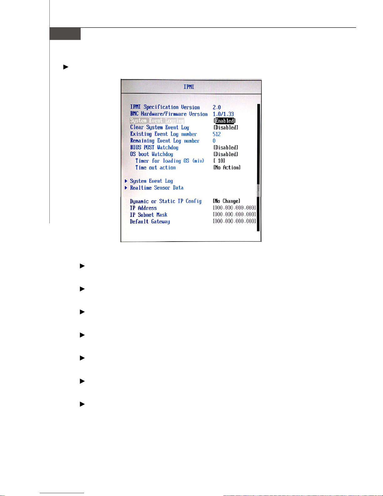
IPMI Specification Version
Indicate the IPMI (Intelligent Platform Management Interface) version.
BMC Hardware/Firmware Version
Indicate the BMC (Baseboard Management Controller) version.
System Event Logging
This function is used to log system events.
Clear System Event Log
This function is used to clear system event logs.
Existing Event Log Number
Indicates how many event logs are existing.
Remaining Event Log Number
Indicates how many event logs are remaining.
BIOS POST Watchdog
Setting the option to [Enabled] If BIOS POST fails, Watchdog restarts the BIOS
POST.
3-16
Page 67

BIOS Setup
OS boot Watchdog
Setting the option to [Enabled] If OS boot fails, Watchdog Timer reboots the OS.
Timer for loading OS (min)
This setting specifies the timer for loading OS. It will take an action depend
on the setting of Time out action after time out.
Time out action
This setting determines what action to take if OS fails to boot.
System Event Log
This setting shows the system event logs.
Realtime Sensor Data
This setting shows the real-time CPU/system temperature & voltage data on the
system monitor sensor.
3-17
Page 68

MS-9238 Server
Dynamic or Static IP Config
This setting is used to configure your dynamic (temporary) or static (permanent)
network IP.
IP Address, IP Subnet Mask, Default Gateway
Use these settings to set up the IP address, IP subnet mask, and default gateway for your system network.
Legacy USB Support
Set to [Enabled] if you need to use any USB 1.1/2.0 device in the operating system
that does not support or have any USB 1.1/2.0 driver installed, such as DOS and SCO
Unix. Set to [Disabled] only if you want to use any USB device other than the USB
mouse.
3-18
Page 69

Security
BIOS Setup
Supervisor Password Is, User Password Is
These items indicate the status of password settings.
Set Supervisor Password
Supervisor Password controls access to the BIOS Setup utility.
Set User Password
User Password controls access to the system at boot.
Password on Boot
Choosing [Enabled] requires a password on boot. It requires prior setting of the
supervisor password. If the supervisor password is set and this option is disabled,
BIOS assumes the user is booting.
Chassis Intrusion
The field enables or disables the feature of recording the chassis intrusion status
and issuing a warning message if the chassis is once opened.
Reset Chassis Intrusion
The field is used to clear the chassis intrusion warning message.
3-19
Page 70

MS-9238 Server
Power
Important
S3-related functions are available only when your BIOS supports S3 sleep mode.
Power Button Function
This feature allows users to configure the power button function. Settings are:
[Instant-Off] The power button functions as a normal power-on/-off
button.
[Delay 4 Second]When you press the power button, the computer enters
the suspend/sleep mode, but if the button is pressed for
more than four seconds, the computer is turned off.
Wake On LAN/PME
The item specifies how the system will be awakened from power saving mode when
input signal of the LAN/PME is detected.
3-20
Page 71

BIOS Setup
After Power Failure
This setting specifies whether your system will reboot after a power failure or
interrupt occurs. Available settings are:
[Stay Off] Returns the system to an off state.
[Power On] Returns the system to a full on state.
[Last State] Restores the system to the previous status before power
failure or interrupt occurred.
Resume On Modem Ring
The item specifies how the system will be awakened from power saving mode when
input signal of the Modem Ring is detected.
Resume On Time
Select [On] to wake up the system at predetermined time.
Resume Time
The time format is <HH> <MM> <SS>.
3-21
Page 72

MS-9238 Server
Boot
These settings allow users to set the priority of the specified devices.You may use
the arrow keys ( ↑↓ ) to select the desired device, <+>/<-> key to move it up/down
in the priority list, <x> key to exclude or include the device to boot, (Shift + 1) to enable
or disable a device, (1 - 4) keys to load default boot sequence.
3-22
Page 73

Exit
BIOS Setup
Exit Saving Changes
Save changes to CMOS and exit setup.
Exit Discarding Changes
Abandon all changes and exit setup.
Load Setup Defaults
Use this menu to load the default values set by the BIOS vendor for stable system
performance.
Discard Changes
Abandon all changes.
Save Changes
Save changes to CMOS.
3-23
Page 74

MS-9238 Server
3-24
Page 75

Adaptec SATA RAID
Appendix A
Adaptec SATA RAID
The Southbridge provides a hybrid solution that combines six independent SATAII ports for support of up to
six Serial ATAII (Serial ATAII RAID) drives.
It offers RAID level 0 (Striping), RAID level 1 (Mirroring
and Duplexing) and RAID level 10 (A Stripe of Mirrors).
A-1
Page 76

MS-9238 Server
Introduction
The Southbridge provides a hybrid solution that combines six independent SATAII
ports for support of up to six SATAII (or four SATAII RAID 10) drives.
Serial ATAII (SATAII) is the latest generation of the ATA interface. SATA hard drives
deliver blistering transfer speeds up to 300MB/sec. Serial ATA uses long, thin cables,
making it easier to connect your drive and improving the airflow inside your PC. The
most outstanding features are:
1. Supports 300MB/s transfers with CRC error checking.
2. Supports Hot-plug-n-play feature.
3. Data handling optimizations including tagged command queuing, elevator seek
and packet chain command.
The Intel Southbridge offers RAID level 0 (Striping), RAID level 1 (Mirroring and
Duplexing) and RAID level 10 (A Stripeof Mirrors).
RAID 0 breaks the data into blocks which are written to separate hard drives. Spreading
the hard drive I/O load across independent channels greatly improves I/O performance.
RAID 1 provides data redundancy by mirroring data between the hard drives and
provides enhanced read performance.
RAID 10 Not one of the original RAID levels, multiple RAID 1 mirrors are created, and
a RAID 0 stripe is created over these. Intel Matrix RAID Technology is the advanced
ability for two RAID volumes to share the combined space of two hard drives being
used in unison.
Important
1. The least number of hard drives for RAID 0 or RAID 1 is 2. The least
number of hard drives for RAID 10 mode is 4.
2. All the information/volumes listed in your system might differ from the
illustrations in this appendix.
3. When installing SuSE OS under SATA RAID & AHCI mode, once the OS
boots from the CD-ROM, select F3 or F5 as requested to add drivers.
Then toggle to “ Installation” and, at the command prompt, type
“broken_modules=ahci”
4. RAID support on Linux OS will be changed by vendors. Please contact
MSI Sales if you need SATA RAID support on Linux OS.
A-2
Page 77
Adaptec SATA RAID
BIOS Configuration
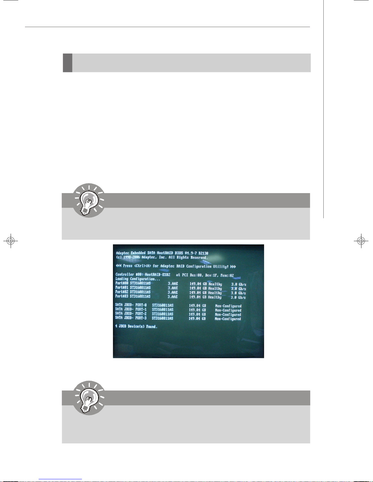
The Adaptec SATA Option ROM should be integrated with the system BIOS on all
motherboards with a supported Intel chipset. The Adaptec Option ROM is the Adaptec
RAID implementation and provides BIOS and DOS disk services. Please use <Ctrl> +
<A> keys to enter the “Adaptec Embedded SATA HostRAID” status screen, which
should appear early in system boot-up, during the POST(Power-On Self Test). Also,
you need to enable the RAID function in BIOS to create, delete and reset RAID
volumes.
Using the Adaptec SATA HostRAID Option ROM
Creating and Deleting RAID Volumes:
The Serial ATA RAID volume may be configured using the RAID Configuration utility
stored within the Adaptec RAID Option ROM. During the Power-On Self Test (POST),
the following message will appear for a few seconds:
Important
The “Driver Model”, “Serial #” and “Size” in the following example might be
different from your system.
After the above message shows, press <Ctrl> and <A> keys simultaneously to enter
the RAID Configuration Utility.
Important
The following procedure is only available with a newly-built system or if you
are reinstalling your OS. It should not be used to migrate an existing system
to RAID.
A-3
Page 78

MS-9238 Server
After pressing the <Ctrl> and <A> keys simultaneously, the following window will
appear:
(1) Create RAID Volume
1. Enter Array Configuration Utility. Select option “Create array” and press
<Enter> key. The following screen appears.
A-4
Page 79

Adaptec SATA RAID
Then in the Select drivers to create Array field, specify the devices and
then press the <Enter> key to go to the next field.
2. Use the arrow keys to select the RAID level best suited to your usage model
in RAID Level.
A-5
Page 80

MS-9238 Server
3. Then Enter the Array Label name, and pressing the <Enter> key to select and
advance to the next field. The available values range from 16KB to 64 KB in
power of 2 increments. The strip value should be chosen based on the
planned drive usage. Here are some typical values:
RAID0 – 64KB
RAID10 – 64KB
4. Then select the Create RAID via Quick Init, and select [Done] to finish the
creation.
A-6
Page 81

Adaptec SATA RAID
5. Enter Manager Arrays to confirm if the creation is finished.
A-7
Page 82

MS-9238 Server
(2) Delete RAID Volume
Here you can delete the RAID volume, but please be noted that all data on RAID
drives will be lost.
Important
If your system currently boots to RAID and you delete the RAID volume in the
Adaptec RAID Option ROM, your system will become unbootable.
Select option Manager Arrays from the main menu window and press <Enter>
key to select a RAID volume for deletion. Then press <Delete> key to delete the
selected RAID volume. The following screen appears.
A-8
Page 83

Adaptec SATA RAID
Select [Delete], and press <Enter>. The following screen appears:
Press <Y> key to accept the volume deletion.
A-9
Page 84

MS-9238 Server
A-10
Page 85

LSI SAS RAID
Appendix B
LSI SAS RAID
This appendix explains how to configure and use the
components of the LSI Logic Integrated RAID (IR) software with LSI SAS 1064/1064E & 1068/1068E
controllers.
B-1
Page 86

MS-9238 Server
1. Introduction to Integrated RAID
This section provides an overview of the LSI Logic Integrated RAID solution for LSI
Logic SAS controllers, its features, and its benefits.
The LSI Logic Integrated RAID solution provides cost benefits for the server or
workstation market where the extra performance, storage capacity, and/or redundancy of a RAID configuration are required. The two components of Integrated RAID
are:
Integrated Mirroring (IM), which provides features of RAID 1 and RAID 1E
(RAID 1 Enhanced). RAID 1E is also called Integrated Mirroring Enhanced
(IME)
Integrated Striping (IS), which provides features of RAID 0
By simplifying the IM and IS configuration options and by providing firmware support
in its host adapters, LSI Logic can offer the Integrated RAID solution at a lower cost
than a hardware RAID implementation.
Fusion-MPT™ firmware supports IM and IS volumes. You can configure IM and IS
volumes together on the same LSI Logic SAS controller.
Integrated RAID Benefits and Features
Low cost RAID volume creation meets the needs of most internal RAID instal-
lations
Easy to use - installation and configuration are not complex
System can boot from an IM, IME, or IS volume
No special OS-specific software required
High reliability and data integrity
– Non-volatile write journaling
– Physical disks not visible to OS or to application software
Low host CPU and PCI bus utilization
Fusion-MPT architecture provides processing power
– Shared memory architecture minimizes external memory requests
– Functionality is contained in device hardware and firmware
B-2
Page 87

LSI SAS RAID
2. Integrated Mirroring Overview
This section provides an overview of the LSI Logic Integrated Mirroring (IM) feature.
2.1 Introduction
As a result of the shift towards Network Attached Storage (NAS), ISPs need a cost
effective, fault-tolerant solution to protect the operating systems on small form factor,
high-density, rack-mountable servers. The LSI Logic Integrated Mirroring (IM) feature—which includes Integrated Mirroring Enhanced (IME)—provide data protection
for the system boot volume to safeguard critical information such as the operating
system on servers and high performance workstations. The Integrated Mirroring
feature gives customers a robust, high-performance, fault-tolerant solution to their
storage needs, at a lower cost than a dedicated RAID controller.
The Integrated Mirroring feature supports simultaneous mirrored volumes with two
disks (IM) or three to eight disks (IME), to provide fault-tolerant protection for critical
data. (If a hot spare disk is used, the maximum volume size is seven mirrored disks,
plus the hot spare disk.) Up to two IM volumes are supported per SAS controller, with
up to ten drives total per controller.
v Note: Ten disk drives is the theoretical upper limit, although the SAS controller
itself may support fewer drives.
If a disk in an Integrated Mirroring volume fails, the hot swap capability allows the
volume to be easily restored by simply swapping disks. The firmware then automatically re-mirrors the swapped disk. Additionally, each SAS controller can have one
global hot spare disk available to automatically replace a failed disk in the one or two
IM or IME volumes configured on the controller. The hot spare makes the Integrated
Mirroring volume even more fault-tolerant.
v Note: You can configure an Integrated Mirroring volume and an Integrated Striping
volume on the same LSI Logic SAS controller.
The IM feature uses the same device drivers as the standard LSI Logic Fusion-MPT
based controllers, providing seamless and transparent fault tolerance. This eliminates the need for complex backup software or expensive RAID hardware. The IM
feature operates independently from the operating system, in order to conserve
system resources. The BIOSbased configuration utility makes it easy to configure IM
and IME volumes.
The Integrated Mirroring feature is currently available as an optional component of
the Fusion-MPT architecture on LSI Logic controller products.
B-3
Page 88

MS-9238 Server
2.2 IM Features
LSI Logic Integrated Mirroring and Integrated Mirroring Enhanced support the following features:
Configurations of one or two IM or IME volumes on the same LSI Logic SAS
controller. Each volume can consist of two mirrored disks (IM) or three to eight
mirrored disks (IME).
(Optional) One global hot spare disk per controller. If a global hot spare disk is
defined, the upper limit for an IME volume is seven mirrored disks.
Mirrored volumes run in optimal mode or in degraded mode (if one mirrored disk
fails)
Hot swap capability
Presents a single virtual drive to the OS for each IM/IME volume
Supports both SAS and SATA disks, although the two types of disks cannot be
combined on the same LSI Logic SAS controller
Fusion-MPT architecture
Easy-to-use BIOS-based configuration utility (and DOS-based configuration
utility for manufacturing use only)
Error notification: OS-specific event log updated by drivers and errors dis-
played inside the Fusion-MPT BIOS
SES status LED support for Integrated Mirroring disks
Write journaling, which allows automatic synchronization of potentially incon-
sistent data after unexpected power-down situations
Metadata used to store volume configuration on mirrored disks
Automatic background resynchronization while host I/Os continue
Background media verification ensures that data on the IM volume is acces-
sible
B-4
Page 89

LSI SAS RAID
2.3 IM/IME Description
The LSI Logic Integrated Mirroring (IM) feature supports one or two mirrored volumes
on each LSI Logic SAS controller (or one mirrored volume and one Integrated Striping
volume). Typically, one of these volumes is the boot volume, as shown in Figure 2.1.
This is accomplished through the firmware of the LSI Logic SAS controller that
supports the standard Fusion-MPT interface. The runtime mirroring of the boot disk is
transparent to the BIOS, drivers, and operating system.
Host-based status software monitors the state of the mirrored disks and reports any
error conditions. In Figure 2.1 the system is configured with a second disk as a mirror
of the first (primary) disk.
The advantage of Integrated Mirroring (RAID 1), is that there is always a mirrored
copy of the data. The disadvantage is that writes take longer because data must be
written twice. On the other hand, performance is actually improved during reads.
Figure 2.2 shows the logical view and physical view of an Integrated Mirroring
configuration with two disks in the mirrored volume.
B-5
Page 90

MS-9238 Server
An IME volume can be configured with up to eight mirrored disks, or seven mirrored
disks and a global hot spare. Figure 2.3 shows the logical view and physical view of
an Integrated Mirroring Enhanced (IME) volume with three mirrored disks. Each mir-
rored stripe is written to a disk and mirrored to an adjacent disk. This type of configuration is also called RAID 1E.
LSI Logic provides the BIOS-based configuration utility to enable the user to create IM
and IME volumes during initial setup and to reconfigure them in response to hardware
failures or changes in the environment.
B-6
Page 91

LSI SAS RAID
2.4 Integrated Mirroring Firmware
This section describes features of the LSI Logic Integrated Mirroring (IM) firmware,
which supports up to two IM volumes per LSI Logic SAS controller.
2.4.1 Host Interface
The IM host interface uses the Message Passing Interface, as described in the
Fusion-MPT Message Passing Interface Specification. Through the FusionMPT interface, the host OS has access to the IM volume as well as the physical
disks.
2.4.2 Resynchronization with Concurrent Host I/O Operation
The IM firmware allows Host I/Os to continue on the IM/IME volume while the
volume is being re-synchronized in the background. Resynchronization is attempted after a hot spare is activated due to a physical device failure, or after
a hot swap has occurred to a physical disk in the IM or IME volume.
2.4.3 Metadata Support
The firmware supports metadata, which describes the IM/IME logical drive configuration stored on each member disk. When the firmware is initialized, each
member disk is queried to read the stored metadata in order to verify the
configuration. The usable disk space for each member disk is adjusted down to
leave room for this data.
2.4.4 Hot Swapping
The IM firmware supports hot swapping. The hot-swapped disk is automatically
resynchronized in the background, without any host or user intervention. The
firmware detects hot swap removal and disk insertion.
Following a hot swap event, the firmware readies the new physical disk by
spinning it up and verifying that it has enough capacity for the mirrored volume.
The IM firmware resynchronizes all hot-swapped disks that have been removed,
even if the same disk is re-inserted. In a two-disk mirrored volume, the IM
firmware marks the hot-swapped disk as the secondary disk and marks the
other mirrored disk as the primary disk. The firmware resynchronizes all data
from the primary disk onto the new secondary disk.
2.4.5 SMART Support
The IM firmware enables Mode 6 SMART on the member disks in the mirrored
volume. Mode 6 SMART requires each physical disk to be polled at regular
intervals. If a SMART ASC/ASCQ code is detected on a physical disk in the
volume, the firmware processes the SMART data, and the last received SMART
ASC/ASCQ is stored in non-volatile memory. The IM/IME volume does not support SMART directly, since it is just a logical representation of the physical disks
in the volume.
2.4.6 Hot Spare Disk
One disk can be configured as a global hot spare disk, which protects data on
the one or two volumes configured on the controller. If the IM firmware fails one
of the mirrored disks, the firmware automatically replaces it with the hot spare
B-7
Page 92

MS-9238 Server
disk. The IM firmware then resynchronizes the mirrored data. The IM firmware
is automatically notified when the failed disk has been replaced, and the firmware then designates that disk as the new hot spare.
2.4.7 Media Verification
The IM firmware supports a background media verification feature that runs at
regular intervals when the IM/IME volume is in optimal mode. If the verification
command fails for any reason, the other disk’s data for this segment is read and
written to the failing disk in an attempt to refresh the data. The current Media
Verification Logical Block Address is written to non-volatile memory occasionally to allow Media Verification to continue approximately where it left off prior
to a power-cycle.
2.4.8 Disk Write Caching
The IM firmware disables disk write caching by default. This is done to increase
data integrity, so that the disk write log stored in NVSRAM is always valid. If
disk write caching were enabled (not recommended), the disk write log could
be invalid.
2.4.9 NVSRAM Usage
For the LSISAS1064/1064E and LSISAS1068/1068E controllers, the IM firmware requires at least a 32K NVSRAM in order to perform write journaling.
Write journaling is used to verify that the mirrored disks in the IM/IME volume are
synchronized with each other.
2.5 Fusion-MPT Support
The BIOS uses the LSI Logic Fusion-MPT interface to communicate to the SAS controller and firmware to enable Integrated Mirroring. This includes reading the FusionMPT configuration to gain access to the parameters that are used to define behavior
between the SAS controller and the devices connected to it. The Fusion-MPT drivers
for all supported operating systems implement the Fusion-MPT interface to communicate with the controller and firmware.
B-8
Page 93

LSI SAS RAID
3. Creating Integrated Mirroring Volumes
This section describes how to create Integrated Mirroring (IM) and Integrated Mirroring Enhanced (IME) volumes using the LSI Logic SAS BIOS Configuration Utility (SAS
BIOS CU).
3.1 IM Configuration Overview
You can use the SAS BIOS CU to create one or two IM or IME volumes on each LSI
Logic SAS controller, with an optional global hot spare disk. All disks in an IM or IME
volume must be connected to the same LSI Logic SAS controller.
Although you can use disks of different size in IM and IME volumes, the smallest disk
determines the “logical” size of each disk in the volume. In other words, the excess
space of the larger member disk is not used.
Refer to Section 2.2, “IM Features,” for more information about Integrated Mirroring
volumes.
3.2 Creating IM and IME Volumes
The SAS BIOS CU is part of the Fusion-MPT BIOS. When the BIOS loads during boot
and you see the message about the LSI Logic Configuration Utility, press Ctrl-C to
start the CU. After you do this, the message changes to:
Please wait, invoking SAS Configuration Utility...
After a brief pause, the main menu of the SAS BIOS CU appears. On some systems,
however, the following message appears next:
LSI Logic Configuration Utility will load following initialization!
In this case, the SAS BIOS CU will load after the system has completed its power-on
self test.
You can configure one or two IM or IME volumes per Fusion-MPT controller. You can
also combine IM, IME, and Integrated Striping volumes on the same controller, up to a
maximum of 10 physical disk drives.
The following guidelines also apply when creating an IM or IME volume:
All physical disks in the volumes must be either SATA (with extended command
set support) or SAS (with SMART support). SAS and SATA disks cannot be
combined in the same volume.
Disks must have 512-byte blocks and must not have removable media.
An IM volume must have two drives, plus an optional global hot spare. An IME
volume. An IME volume can have three to eight drives, or three to seven drives
if you also create a global hot spare.
v Note: If a disk in an IM or IME volume fails, it is rebuilt on the global hot spare if one
B-9
Page 94

MS-9238 Server
is available. So adding a global hot spare greatly increases the level of data
protection. (One global hot spare is allowed for the one or two volumes config
ured on a controller.)
3.2.1 Creating an IM Volume
Follow these steps to create an IM volume with the SAS BIOS CU:
1. On the Adapter List screen, use the arrow keys to select an LSI Logic SAS
adapter.
2. Press Enter to go to the Adapter Properties screen, shown in Figure 3.1.
3. On the Adapter Properties screen, use the arrow keys to select RAID Proper-
ties on the screen and press Enter.
4. When you are prompted to select a volume type, select Create IM Volume.
The Create New Array screen shows a list of disks that can be added to a
volume.
5. Move the cursor to the “RAID Disk” column and select a disk. To add the disk to
the volume, change the “No” to “Yes” by pressing the + key, . key, or space
bar. When the first disk is added, the SAS BIOS CU prompts you to either keep
existing data or overwrite existing data.
6. Press M to keep the existing data on the first disk or press D to overwrite it. If
you keep the existing data, this is called a migration. The first disk will be
mirrored onto the second disk, so the data you want to keep must be on the
first disk added to the volume. Any data on the second disk is overwritten. As
disks are added the Array Size field changes to reflect the size of the new
volume.
7. (optional) Add a global hot spare by moving the cursor to the hot spare column
and pressing the + key, . key, or space bar.
B-10
Page 95

LSI SAS RAID
Figure 3.2 shows an IM volume configured with a global hot spare disk.
8. When the volume has been fully configured, press C and then select Save
changes then exit this menu to commit the changes. The SAS BIOS CU
pauses while the array is being created.
3.2.2 Creating an IME Volume
Follow these steps to create an IME volume with the SAS BIOS CU:
1. On the Adapter List screen, use the arrow keys to select an LSI Logic SAS
adapter.
2. Press Enter to go to the Adapter Properties screen, shown in Figure 3.1.
3. On the Adapter Properties screen, use the arrow keys to select RAID Proper-
ties on the screen and press Enter.
4. When you are prompted to select a volume type, select Create IME Volume.
The Create New Array screen shows a list of disks that can be added to a
volume.
5. Move the cursor to the “RAID Disk” column and select a disk. To add the disk to
the volume, change the “No” to “Yes” by pressing the + key, . key, or space
bar.
6. Repeat this step to select a total of three to eight disks for the volume (or three
to seven disks if you will create a global hot spare). All existing data on all the
disks you select will be overwritten. As you add disks, the Array Size field
changes to reflect the size of the new volume.
7. (optional) Add a global hot spare to the volume by moving the cursor to the hot
spare column and pressing the + key, . key, or space bar.
8. When the volume has been fully configured, press C and then select Save
changes then exit this menu to commit the changes. The SAS BIOS CU
pauses while the array is being created.
B-11
Page 96

MS-9238 Server
3.3 Creating a Second IM or IME Volume
The LSI Logic SAS controllers allow you to configure two IM or IME volumes. If one
volume is already configured, and if there are available disk drives, there are two
ways to add a second volume.
The first is as follows:
1. In the configuration utility, select an adapter from the Adapter List. Select the
RAID Properties option. This will display the current volume.
2. Press C to create a new volume.
3. Continue with step 4 of the IM or IME creation procedure in the previous section
to create a second volume.
The other way in which to add a second volume is as follows:
1. On the Adapter List screen, use the arrow keys to select an LSI Logic SAS
adapter.
2. Press Enter to go to the Adapter Properties screen, shown in Figure 3.1.
3. On the Adapter Properties screen, use the arrow keys to select RAID Proper-
ties and press Enter.
4. Continue with step 4 of the IM or IME creation procedure in the previous section
to create a second volume.
B-12
Page 97

LSI SAS RAID
3.4 Managing Hot Spares
You can create one global hot spare disk to protect the one or two IM/IME volumes
defined on a SAS controller. Usually, you create the global hot spare at the same time
you create the IM/IME volume. Follow these steps to add a global hot spare disk later
for the existing IM/IME volumes on the controller:
1. On the View Array screen, select Manage Array.
2. Select Manage Hot Spare on the Manage Array screen, shown in Figure 3.3.
3. Select a disk from the list by pressing the + key, . key, or space bar.
4. After you select the global hot spare disk, press C. An error message appears
if the selected disk is not at least as large as the smallest disk used in the IM/
IME volume(s). The global hot spare disk must have 512-byte blocks, it cannot
have removable media, and the disk type must be either SATA with extended
command set support or SAS with SMART support. If SATA disks are used for
the IM/IME volume(s), the hot spare disk must also be a SATA disk. If SAS disks
are used, the hot spare disk must also be a SAS disk. An error message
appears if the selected disk is not the same type as the disks used in the IM/IME
volumes.
5. Select Save changes then exit this menu to commit the changes. The
configuration utility will pause while the global hot spare is being added.
Follow these steps to delete a global hot spare:
1. Select Manage Hot Spare on the Manage Array screen.
2. Select Delete Hot Spare and then press C.
3. Select Save changes then exit this menu to commit the changes. The
configuration utility will pause while the global hot spare is being removed.
B-13
Page 98

MS-9238 Server
3.5 Other Configuration Tasks
This section explains how to do other tasks related to configuring and maintaining IM
and IME volumes.
3.5.1 Viewing Volume Properties
Follow these steps to view the properties of volumes:
1. In the SAS BIOS CU, select an adapter from the Adapter List. Select the RAID
Properties option. The properties of the current volume are displayed. If a
global hot spare is defined, it is also listed.
v Note: If you create one volume using SAS disks, another volume using SATA
disks, and a global hot spare disk, the hot spare disk will only appear when
you view the volume that has the same type of disks as the hot spare disk.
2. If two volumes are configured, press Alt+N to view the other array.
3. To manage the current array, select the Manage Array item and press Enter.
3.5.2 Synchronizing an Array
The Synchronize Array command forces the firmware to resynchronize the data on
the mirrored disks is the array. It is seldom necessary to use this command, because
the firmware automatically keeps the mirrored data synchronized during normal system operation. When you use this command, one disk of the array is placed in the
Degraded state until the data on the mirrored disks has been resynchronized.
Follow these steps to force the synchronization of a selected array:
1. Select Synchronize Array on the Manage Array screen.
2. Press Y to start the synchronization, or N to cancel it.
3.5.3 Activating an Array
An array can become inactive if, for example, it is removed from one controller or
computer and moved to another one. The “Activate Array” option allows you to
reactivate an inactive array that has been added to a system. This option is only
available when the selected array is currently inactive.
Follow these steps to activate a selected array
1. Select Activate Array on the Manage Array screen.
2. Press Y to proceed with the activation, or press N to abandon it. After a pause,
the array will become active.
v Note: If there is a global hot spare disk on the controller to which you have
moved the array, the firmware checks when you activate the array to determine if the hot spare is compatible with the new array. An error message
appears if the disks in the activated array are larger than the hot spare disk or
if the disks in the activated array are not the same type as the hot spare disk
(SATA versus SAS).
3.5.4 Deleting an Array
v CAUTION: Before deleting an array, be sure to back up all data on the array that
you want to keep.
B-14
Page 99

LSI SAS RAID
Follow these steps to delete a selected array:
1. Select Delete Array on the Manage Array screen.
2. Press Y to delete the array.
After a pause, the firmware deletes the array. If there is another remaining
array and a global hot spare disk, the firmware checks the hot spare disk to
determine if it is compatible with the remaining array. If the hot spare disk is not
compatible (too small or wrong disk type) the firmware deletes it also.
v Note: After a volume has been deleted, it cannot be recovered. When a RAID
1 volume is deleted, the data is preserved on the primary disk. The master boot
records (MBR) of other disks in the array are deleted. For other RAID types,
the master boot records of all disks are deleted.
3.5.5 Locating a Disk Drive, or Multiple Disk Drives in a Volume
You can use the SAS BIOS CU to locate and identify a specific physical disk drive by
flashing the drive’s LED. You can also use the SAS BIOS CU to flash the LEDs of all
the disk drives in a RAID volume. There are several ways to do this:
When you are creating an IM or IME volume, and a disk drive is set to Yes as
part of the volume, the LED on the disk drive is flashing. The LED is turned off
when you have finished creating the volume.
You can locate individual disk drives from the SAS Topology screen. To do this,
move the cursor to the name of the disk in the Device Identifier column and
press Enter. The LED on the disk flashes until the next key is pressed.
You can locate all the disk drives in a volume by selecting the volume on the
RAID Properties screen. The LEDs flash on all disk drives in the volume.
v Note: The LEDs on the disk drives will flash as described above if the firmware
is correctly configured and the drives or the disk enclosure supports disk
location.
3.5.6 Selecting a Boot Disk
You can select a boot disk in the SAS Topology screen. This disk is then moved to
scan ID 0 on the next boot, and remains at this position. This makes it easier to set
BIOS boot device options and to keep the boot device constant during device additions and removals. There can be only one boot disk.
Follow these steps to select a boot disk:
1. In the SAS BIOS CU, select an adapter from the Adapter List.
2. Select the SAS Topology option.
The current topology is displayed. If the selection of a boot device is supported,
the bottom of the screen lists the Alt+B option. This is the key for toggling the
boot device. If a device is currently configured as the boot device, the Device
Info column on the SAS Topology screen will show the word “Boot.”
3. To select a boot disk, move the cursor to the disk and press Alt+B.
4. To remove the boot designator, move the cursor down to the current boot disk
and press Alt+B. This controller will no longer have a disk designated as boot.
5. To change the boot disk, move the cursor to the new boot disk and press
Alt+B. The boot designator will move to this disk.
v Note: The firmware must be configured correctly in order for the Alt+B feature
to work.
B-15
Page 100

MS-9238 Server
4. Integrated Striping Overview
This section provides an overview of the LSI Logic Integrated Striping (IS) feature.
4.1 Introduction
The LSI Logic Integrated Striping (IS) feature is useful for applications that require the
faster performance and increased storage capacity of striping. The low-cost IS
feature has many of the advantages of a more expensive RAID striping solution. A
single IS logical drive may be configured as the boot disk or as a data disk.
The IS feature is implemented with controller firmware that supports the Fusion-MPT
Interface. IS provides better performance and more capacity than individual disks,
without burdening the host CPU. The firmware splits host I/Os over multiple disks and
presents the disks as a single logical drive. In general, striping is transparent to the
BIOS, the drivers, and the operating system.
The SAS BIOS CU is used to configure IS volumes, which can consist of two to eight
disks.
v Note: Integrated Mirroring and Integrated Striping volumes can be configured
on the same LSI logic SAS controller.
4.2 IS Features
Integrated Striping supports the following features:
Support for volumes with two to eight drives
Support for two IS volumes, with up to 10 drives total, on a controller. An IS
volume can also be combined with an IM or IME volume.
v Note: Currently available LSI Logic SAS controllers support a maximum of eight
drives. All drives in a volume must be connected to the same SAS controller.
Presents a single virtual drive to the OS for each configured volume
Support for both SAS and SATA drives, although the two types of drives
cannot be combined in one volume
Fusion-MPT architecture
Easy-to-use SAS BIOS configuration utility
Error notification
Use of metadata to store volume configuration on disks
OS-specific event log
Error display inside the Fusion-MPT BIOS
SES status LED support for drives used in IS volumes
B-16
 Loading...