

Page 1
X2-107 Series
MS-9238 1U Rackmount Server
G52-92381X2
i
Page 2

Copyright Notice
The material in this document is the intellectual property of MICRO-STAR
INTERNATIONAL. We take every care in the preparation of this document, but no
guarantee is given as to the correctness of its contents. Our products are under
continual improvement and we reserve the right to make changes without notice.
Trademarks
All trademarks are the properties of their respective owners.
Intel® and Pentium® are registered trademarks of Intel Corporation.
AMD, Athlon™, Athlon™ XP, Thoroughbred™, and Duron™ are registered trademarks of AMD Corporation.
NVIDIA, the NVIDIA logo, DualNet, and nForce are registered trademarks or trademarks of NVIDIA Corporation in the United States and/or other countries.
PS/2 and OS®/2 are registered trademarks of International Business Machines
Corporation.
Windows® 95/98/2000/NT/XP are registered trademarks of Microsoft Corporation.
Netware® is a registered trademark of Novell, Inc.
Award® is a registered trademark of Phoenix Technologies Ltd.
AMI® is a registered trademark of American Megatrends Inc.
Revision History
Revision Revision History Date
V1.1 First release February 2007
Technical Support
If a problem arises with your system and no solution can be obtained from the user’ s
manual, please contact your place of purchase or local distributor. Alternatively,
please try the following help resources for further guidance.
Visit the MSI website at http://www.msi.com.tw/program/service/faq/
faq/esc_faq_list.php for FAQ, technical guide, BIOS updates, driver
updates, and other information.
Contact our technical staff at http://support.msi.com.tw/.
ii
Page 3
Safety Instructions
1. Always read the safety instructions carefully.
2. Keep this User’s Manual for future reference.
3. Keep this equipment away from humidity.
4. Lay this equipment on a reliable flat surface before setting it up.
5. The openings on the enclosure are for air convection hence protects the equipment from overheating. DO NOT COVER THE OPENINGS.
6. Make sure the voltage of the power source and adjust properly 110/220V before connecting the equipment to the power inlet.
7. Place the power cord such a way that people can not step on it. Do not place
anything over the power cord.
8. Always Unplug the Power Cord before inserting any add-on card or module.
9. All cautions and warnings on the equipment should be noted.
10. Never pour any liquid into the opening that could damage or cause electrical
shock.
11. If any of the following situations arises, get the equipment checked by service
personnel:
† The power cord or plug is damaged.
† Liquid has penetrated into the equipment.
† The equipment has been exposed to moisture.
† The equipment does not work well or you can not get it work according to
User’s Manual.
† The equipment has dropped and damaged.
† The equipment has obvious sign of breakage.
12. DO NOT LEAVE THIS EQUIPMENT IN AN ENVIRONMENT UNCONDITIONED, STORAGE TEMPERATURE ABOVE 600 C (1400F), IT MAY DAMAGE THE EQUIPMENT.
CAUTION: Danger of explosion if battery is incorrectly replaced.
Replace only with the same or equivalent type recommended by the
manufacturer.
iii
Page 4

FCC-A Radio Frequency Interference Statement
This equipment has been
tested and found to comply
with the limits for a class A
digital device, pursuant to part
15 of the FCC rules. These limits are designed to provide reasonable protection
against harmful interference when the equipment is operated in a commercial
environment. This equipment generates, uses and can radiate radio frequency energy and, if not installed and used in accordance with the instruction manual, may
cause harmful interference to radio communications. Operation of this equipment in a
residential area is likely to cause harmful interference, in which case the user will be
required to correct the interference at his own expense.
Notice 1
The changes or modifications not expressly approved by the party responsible for
compliance could void the user’s authority to operate the equipment.
Notice 2
Shielded interface cables and A.C. power cord, if any, must be used in order to
comply with the emission limits.
VOIR LA NOTICE D’INSTALLATION AVANT DE RACCORDER AU RESEAU.
Micro-Star International
MS-9238
This device complies with Part 15 of the FCC Rules. Operation is subject to the
following two conditions:
(1) this device may not cause harmful interference, and
(2) this device must accept any interference received, including interference that
may cause undesired operation.
iv
Page 5
WEEE (Waste Electrical and Electronic Equipment) Statement
v
Page 6
vi
Page 7
vii
Page 8

CONTENTS
Copyright Notice...............................................................................................................ii
Trademarks.......................................................................................................................ii
Revision History...............................................................................................................ii
Technical Support............................................................................................................ii
Safety Instructions.........................................................................................................iii
FCC-A Radio Frequency Interference Statement........................................................iv
WEEE (Waste Electrical and Electronic Equipment) Statement....................................v
Chapter 1 Getting Started.....................................................................................1-1
System Overview...............................................................................................1-2
Top View......................................................................................................1-2
Front View...................................................................................................1-3
Front Bezel...................................................................................................1-3
Rear View....................................................................................................1-5
Rear Bezel...................................................................................................1-5
Mainboard Specifications...................................................................................1-6
Mainboard Layout................................................................................................1-8
Chapter 2 Hardware Setup....................................................................................2-1
Quick Components Guide....................................................................................2-2
CPU (Central Processing Unit)............................................................................2-2
Introduction to LGA 771 CPU......................................................................2-3
Memory.................................................................................................................2-4
Memory Population Rules............................................................................2-4
Installing DDRII Modules...............................................................................2-5
Power Supply......................................................................................................2-6
SSI 24-Pin System Power Connector: JPWR2..........................................2-6
SSI 8-Pin CPU Power Connector: JPWR1..................................................2-6
Back Panel............................................................................................................2-7
Connectors..........................................................................................................2-8
Floppy Disk Drive Connector: FDD1............................................................2-8
ATA100 Hard Disk Connector: IDE1............................................................2-8
Serial ATA Connectors: SATA0 ~ SATA3...................................................2-9
Chassis Intrusion Switch Connector: JCI1..............................................2-10
Fan Power Connectors: CPUFAN 1/2, SYSFAN 1/2/3/4/5/6..................2-10
LAN LED Connectors: JACT1, JACT2.......................................................2-11
Front Panel Connector: JFP1.....................................................................2-11
Serial Port Connector: COM 2...................................................................2-12
Front USB Connector: JUSB1, JUSB2.....................................................2-12
viii
Page 9

Ultra320 SCSI Connector: SCSI1..............................................................2-13
Jumpers..............................................................................................................2-14
Clear CMOS Jumper: JBAT1.....................................................................2-14
BIOS Recovery Jumper: J9......................................................................2-15
BIOS Write Protect Jumper: JBIOS1.........................................................2-15
LAN Jumper: JLANDIS1, JLANDIS2..........................................................2-15
Slot......................................................................................................................2-16
PCI (Peripheral Component Interconnect) Express Slot.........................2-16
System Assembly Flowchart...........................................................................2-17
System Assembly..............................................................................................2-19
Removing the Chassis Cover...................................................................2-19
Replacing the Chassis Cover....................................................................2-20
CPU, Heatsink, and Fan Duct....................................................................2-21
Memory.......................................................................................................2-24
Memory Population Rules..........................................................................2-25
Expansion Card..........................................................................................2-26
Hard Disk Drive...........................................................................................2-28
Rack Mounting....................................................................................................2-30
Chapter 3 BIOS Setup.............................................................................................3-1
Entering Setup.....................................................................................................3-2
Control Keys................................................................................................3-3
Getting Help..................................................................................................3-3
General Help <F1>.......................................................................................3-3
The Menu Bar.......................................................................................................3-4
Main......................................................................................................................3-5
Advanced............................................................................................................3-8
Power.................................................................................................................3-16
Security..............................................................................................................3-17
PC Health............................................................................................................3-18
Boot....................................................................................................................3-20
Exit......................................................................................................................3-22
Appendix A Intel SATA RAID (Optional).............................................................A-1
Introduction..........................................................................................................A-2
BIOS Configuration..............................................................................................A-2
Using the Intel Matrix Stroage Manager Option ROM...............................A-3
Appendix B Adaptec SATA RAID (Optional).......................................................B-1
Introduction..........................................................................................................B-2
ix
Page 10

BIOS Configuration..............................................................................................B-3
Using the Adaptec SATA HostRAID Option ROM.......................................B-3
Appendix C SCSI BIOS (Optional)........................................................................C-1
Entering SCSI BIOS.............................................................................................C-2
Control Keys................................................................................................C-2
Selecting the SCSI Channel........................................................................C-2
Selecting the Management Type................................................................C-3
Configure/View SCSI Controller Settings..........................................................C-4
SCSI Bus Interface Definitions....................................................................C-4
Additional Options.......................................................................................C-5
BIOS Information..........................................................................................C-8
Configure/View HostRAID Settings...................................................................C-9
Create RAID Volume....................................................................................C-9
Delete RAID Volume...................................................................................C-15
SCSI Disk Utilities...............................................................................................C-17
x
Page 11

Getting Started
Chapter 1
Getting Started
Thank you for choosing the X2-107 (MS-9238 v1.X), a
high-performance barebone system from MSI.
Based on the innovative Intel® 5000V & ESB2E chipsets
for optimal system efficiency, the X2-107 accommodates the latest Intel® Xeon® (Dempsey/Woodcrest/
Clovertown) processors in Socket LGA771 and supports up to four 240-pin 533/667MHz ECC DDRII FBDIMM slots to provide the maximum of 16GB memory
capacity.
With high scalability, reliability, ease of use, and overall
value, the X2-107 makes an ideal choice for value conscious customers.
1-1
Page 12
MS-9238 Server
2
3
4
5
6
65243
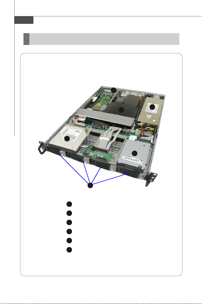
System Overview
Top View
X2-107S4 SCSI Sku and X2-107A4 SATA Sku are available upon request
1
1
HDD Tray
Slim CD-ROM Drive
Slim Floppy Disk Drive
Fan Duct
PCI-Express Bracket
SSI EPS 1U Power Supply
1-2
Page 13
2
3
4
5
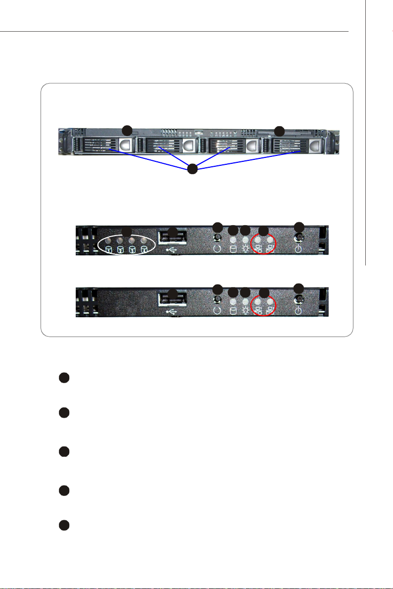
Front View
213
7
910846
5
7
910846
Front Bezel
SCSI
SATA
Getting Started
CD-ROM Drive
1
Slim CD-ROM Drive
Floppy Disk Drive
Slim Floppy Disk Drive
HDD Bay
Swappable Hard Disk Drive Bays
Port
USB Port
LED
HDD Power/Status LEDs
1-3
Page 14

MS-9238 Server
8
9
6
7
HDD Activity LED
This indicator shows the activity status of the hard disk drive. It flashes
when the system is accessing data on the hard disk and remains off when
no disk activity is detected.
Power LED
This indicator shows the power status of the system. It glows when the main
power is turned on.
10
Status LEDs of LAN# 1/2
1. The green LED is on when there is an active connection on the LAN port.
2. This LED flashes when transmitting or receiving activities to or from the
system are detected.
Button
System Reset Button
Power Button
Press this button once to shut down the system, and then once to switch on.
v Front Bezel LEDs
LED Color State Description
Power/Sleep Green On Legacy power on/ACPI S0 state
Red On Sleep/ACPI S1, S4, S5 state
Off Off Power off
HDD Activity Amber Random blink HDD accesss activity
Off Off No disk activity
LAN1/LAN2 Activity Green On LAN link
Green Blink LAN access activity
Swappable HDD Green On Power connected
Power Off Off Power disconnected
Swappable HDD Amber Random blink HDD access
Status w/ SAF-TE Red On Failure or rebuild stopped
Red Slow blink (~1/sec) Rebuild
Red Fast blink (~3/sec) Identification
1-4
Page 15
Rear View
3
4
5
234
5
Rear Bezel
1
PS/2 Keyboard/Mouse Connector2 USB Ports
Serial Port
LAN Jacks
Getting Started
1
VGA Port
v Rear Bezel LEDs
LED Color LED State Condition
RJ45 NIC1 /
NIC2 Link Speed
(Left Side)
RJ45 NIC1 /
NIC2 Access
(Right Side)
Orange On (steady state) LAN link is established.
Green Off 10 Mbit/sec data rate is selected.
Orange On 1000 Mbit/sec data rate is selected.
Off LAN link is not established.
On (brighter & pulsing) The computer is communicating with another
On 100 Mbit/sec data rate is selected.
computer on the LAN.
1-5
Page 16
MS-9238 Server
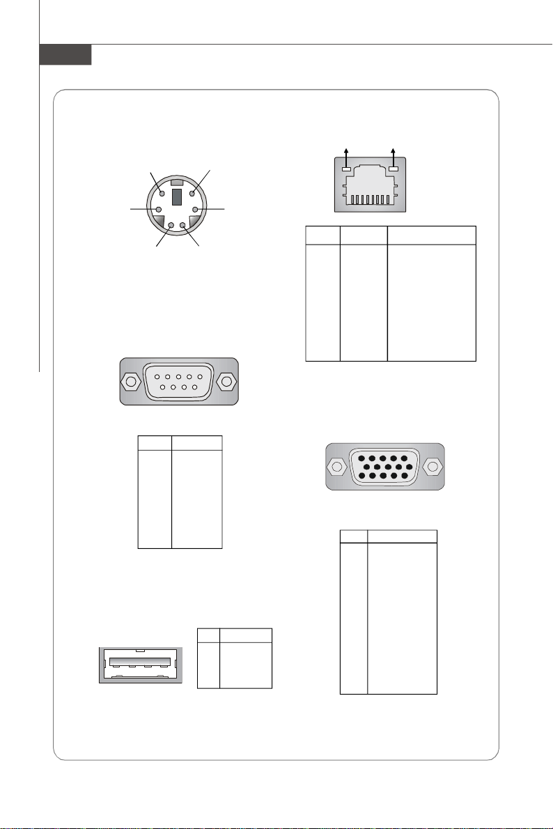
Mouse/Keyboard Connector
Pin6
Mouse Clock
Pin2
Mouse Data
Pin5
Keyboard Clock
Pin1
Keyboard Data
Serial Port
1 2 3 4 5
6 7 8 9
PIN SIGNAL
1 DCD
2 SIN
3 SOUT
4 DTR
5 GND
6 DSR
7 RTS
8 CTS
9 RI
USB Port
1 2 3 4
PIN SIGNAL
1 VCC
2 -Data
3 +Data
4 GND
Gigabit LAN Jack
Link Indicator
Pin3 GNDPin4 VCC
PIN SIGNAL DESCRIPTION
1 D0P Differential Pair 0+
2 D0N Differential Pair 03 D1P Differential Pair 1+
4 D2P Differential Pair 2+
5 D2N Differential Pair 26 D1N Differential Pair 17 D3P Differential Pair 3+
8 D3N Differential Pair 3-
Activity Indicator
8 1
VGA Port
5
15
PIN SIGNAL
1 RED
2 GREEN
3 BLUE
4 N/C
5 GND
6 GND
7 GND
8 GND
9 +5V
10 GND
11 N/C
12 SDA
13 Horizontal Sync
14 Vertical Sync
15 SCL
1
11
1-6
Page 17
Getting Started
Mainboard Specifications
Processor Support
- Supports dual Intel® Xeon® (Dempsey/Woodcrest/Clovertown)
processors in Socket LGA771
- Supports Intel EM64T, DEP (XD bit)
Supported FSB
- FSB 667/1066/1333MHz
Chipset
- Northbridge: Intel® 5000V
- Southbridge: Intel® ESB2E
Memory Support
- 4 DDRII 533/667 FB-DIMM (Fully Buffered Dual-In-line DIMM) slots
- Maximum 16GB
LAN
- Supports dual Gigabit Ethernet by Intel 82563EB
SCSI (Optional)
- SCSI interface supported by Adaptec AIC-7901 Ultra-320 SCSI controller
- Supports Single-Channel Ultra320 LVD SCSI
SATA
- 4 SATAII ports support 4 SATAII devices
- Storage and data transfers at up to 300 MB/s
IDE
- 1-channel bus master IDE port
- Supports ATA100/66
Floppy
- 1 floppy port
Graphics
- XGI VolariTM Z7 graphics processor
- 16MB graphics memory
1-7
Page 18
MS-9238 Server
Connectors
Back Panel
- 1 x PS/2 mouse port
- 1 x PS/2 keyboard port
- 1 x serial port
- 1 x VGA port
- 2 x USB 2.0 ports
- 2 x individual RJ-45 Gigabit LAN ports
Onboard Pinheaders
- 2 x USB 2.0 pinheaders
- 1 x COM port pinheader
- 1 x front panel pinheader
- 1 x chassis intrusion pinheader
Slots
- 1 x PCI-Express x8 slot
Form Factor
- SSI CEB: 12” X 10.5”
Mounting
- 7 mounting holes
1-8
For more information on compatible components, please visit
http://www.msi.com.tw/program/products/server/svr/pro_svr_qvl.php
Page 19
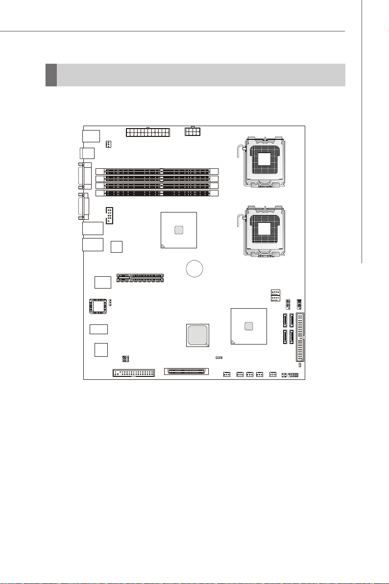
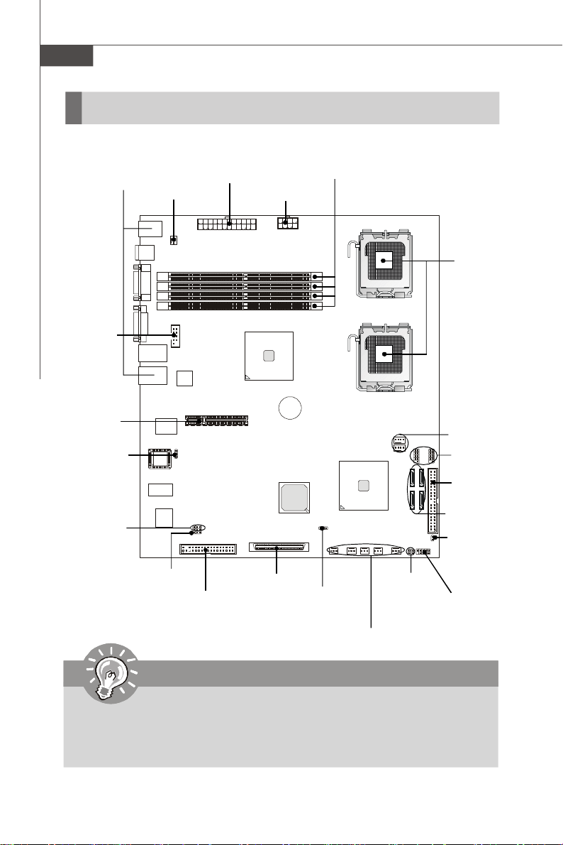
Mainboard Layout
JFP1
JBAT1
Getting Started
FBD12
FBD11
FBD02
FBD01
SYSFAN5
CPU1
CPU2
CPUFAN1
CPUFAN2
Intel
ESB2E
SYSFAN2
SYSFAN6SYSFAN3
SYSFAN4
JUSB2JUSB1
IDE1
SATA1
SATA0
SATA3
SATA2
JCI1
JACT1
JACT2
T: Mouse
B: Keyboard
USB
Ports
COM1
JVG A1
LAN1
LAN 2
Winbobd
W83627HG-AW
BIOS
SYSFAN1
COM2
JBIOS1
JLANDIS1
JLANDIS2
FDD1
SCSI1
Intel
5000V
JPWR1
BATT
+
JPWR2
PCIE2
J9
5000V Master (MS-9638 v1.X) SSI CEB Server Board
1-9
Page 20

MS-9238 Server
1-10
Page 21
Hardware Setup
Chapter 2
Hardware Setup
Refer to the system assembly flowchart and the chart
below to determine the proper sequence of removing
or installing components to the server.
MS-9238
Mainboard Hardware
System Assembly
Rack Mounting
CPU, Memory, Power Supply, Back
Panel, Connectors, Jumpers, Slot
Chassis Cover
CPU, Heatsink
Memory
Riser Card
Hard Disk Drives
Chassis Ears and Rails
Rack Rails
Chassis into the Rack
Chassis off the Rack
2-1
Page 22
MS-9238 Server
Quick Components Guide
Back Panel
I/O, p.2-7
COM2,
p.2-12
PCI Express
Slot, p.2-16
JBIOS1, p.2-15
JLANDIS1/2,
p.2-15
SYSFAN1,
p.2-10
J9, p.2-15
FDD1, p.2-8
JPWR2, p.2-6
DDRII DIMMs, p.2-4
JPWR1, p.2-6
SCSI1,
p.2-13
JBAT1,
p.2-14
JACT2/1,
p.2-11
CPU, p.2-3
CPUFAN1/2,
p.2-10
JUSB1/2,
p.2-12
IDE1,
p.2-8
SATA0~3,
p.2-9
JCI1, p.2-10
JFP1, p.2-11
SYSFAN2/3/4/5/6, p.2-10
Important
CAUTION!!! Please note that the CPU1/CPU2 VRM & memory/south bridge
area should be respectively kept under 105oC and 85oC. To ensure system
stability, always protect the system with proper cooling. Otherwise, overheating may damage the system.
2-2
Page 23
Hardware Setup
CPU (Central Processing Unit)
This mainboard supports the latest Intel® Xeon® (Dempsey/Woodcrest/
Clovertown) processors in Socket LGA771. When you are installing the CPU, make
sure that you install the cooler to prevent the CPU from overheating. If you do not
have a CPU cooler, contact your dealer to purchase and install them before turning on
the computer.
For the latest information about CPU, please visit http://www.msi.com.tw/program/
products/server/svr/pro_svr_qvl.php.
Important
1. Overheating will seriously damage the CPU and system. Always make
sure the cooling fan can work properly to protect the CPU from overheating.
2. Make sure that you apply an even layer of heat sink paste (or thermal tape)
between the CPU and the heatsink to enhance heat dissipation.
3. While replacing the CPU, always turn off the power supply or unplug the
power supply’s power cord from the grounded outlet first to ensure the
safety of CPU.
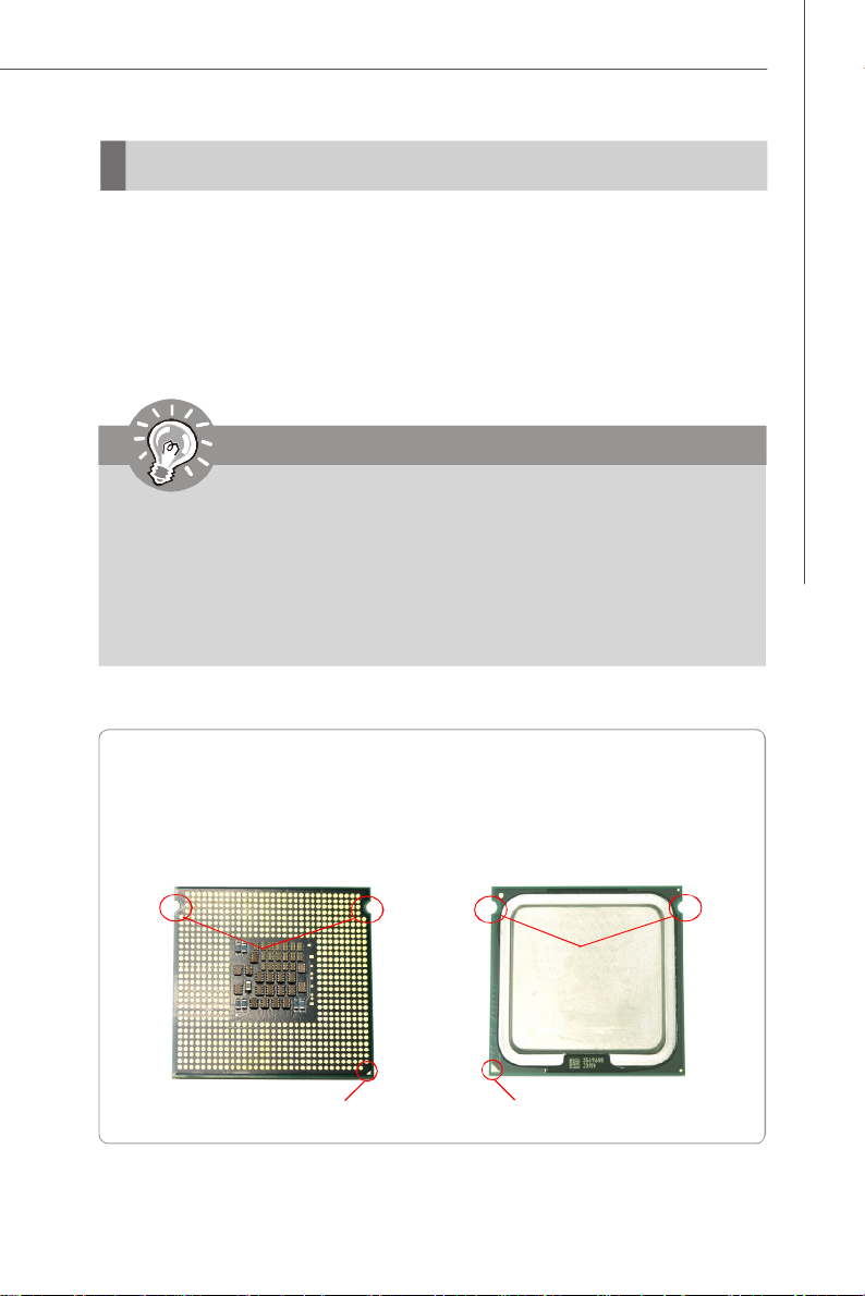
Introduction to LGA 771 CPU
The pin-pad side of LGA 771 CPU.
Alignment Key
Yellow triangle is the Pin 1 indicator
The surface of LGA 771 CPU.
Remember to apply some silicone
heat transfer compound on it for
better heat dispersion.
Alignment Key
Yellow triangle is the Pin 1 indicator
2-3
Page 24
MS-9238 Server
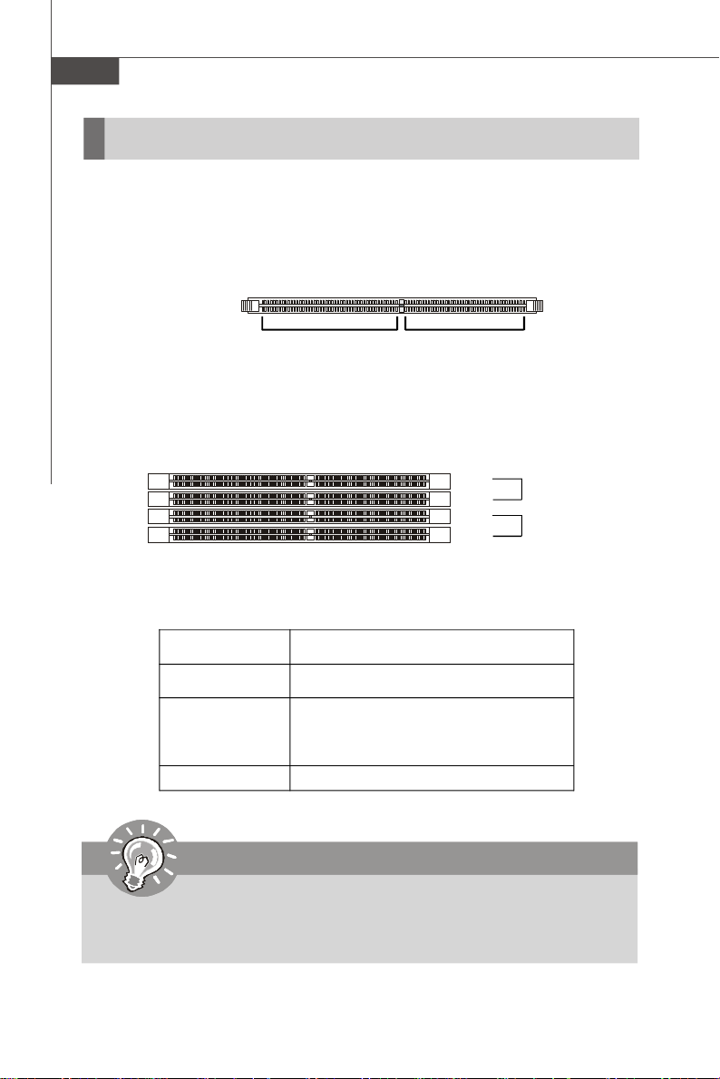
Memory
The mainboard provides four 240-pin 533/667MHz ECC DDRII FB-DIMM slots to support the maximum of 16GB memory capacity.
For more information on compatible components, please visit http://www.msi.com.
tw/program/products/server/svr/pro_svr_qvl.php.
DDRII
240-pin, 1.8V
64x2=128 pin 56x2=112 pin
Memory Population Rules
FBD12
FBD11
FBD02
FBD01
Channel 1
Channel 0
Check the numbers of your DIMM modules and follow the population rules to install the
memory.
Numbers of DIMM Population Rules
1 DIMM Module FBD01
2 DIMM Modules <a> FBD01, FBD02
OR
<b> FBD01, FBD11
4 DIMM Modules FBD01, FBD02, FBD11, FBD12
Important
1. To enable successful system boot-up, always insert the memory modules
into the FBD01 first (Channel 0/ 1st).
2. In dual-channel mode, DIMM modules must be of the same type and density.
2-4
Page 25

Hardware Setup
Installing DDRII Modules
1. The memory module has only one notch on the center and will only fit in the right
orientation.
2. Insert the memory module vertically into the DIMM slot. Then push it in until the
golden finger on the memory module is deeply inserted in the DIMM slot.
Important
You can barely see the golden finger if the memory module is properly inserted
in the DIMM slot.
3. The plastic clip at each side of the DIMM slot will automatically close.
Volt
Notch
2-5
Page 26
MS-9238 Server
Power Supply
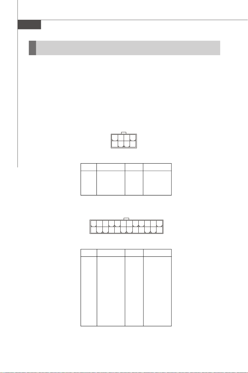
SSI 8-Pin CPU Power Connector: JPWR1
This connector provides 12V power output to the CPUs.
SSI 24-Pin System Power Connector: JPWR2
This connector allows you to connect to an SSI power supply. To connect to the SSI
power supply, make sure the plug of the power supply is inserted in the proper
orientation and the pins are aligned. Then push down the power supply firmly into the
connector.
JPWR1
8 5
4
JPWR1 Pin Definition
PIN SIGNAL
1 GND
2 GND
3 GND
4 GND
1
PIN SIGNAL
5 +12V
6 +12V
7 +12V
8 +12V
2-6
24
12
JPWR2 Pin Definition
PIN SIGNAL
1 +3.3V
2 +3.3V
3 GND
4 +5V
5 GND
6 +5V
7 GND
8 PWR OK
9 5VSB
10 +12V
11 +12V
12 +3.3V
JPWR2
13
1
PIN SIGNAL
13 +3.3V
14 -12V
15 GND
16 PS-ON#
17 GND
18 GND
19 GND
20 Res
21 +5V
22 +5V
23 +5V
24 GND
Page 27
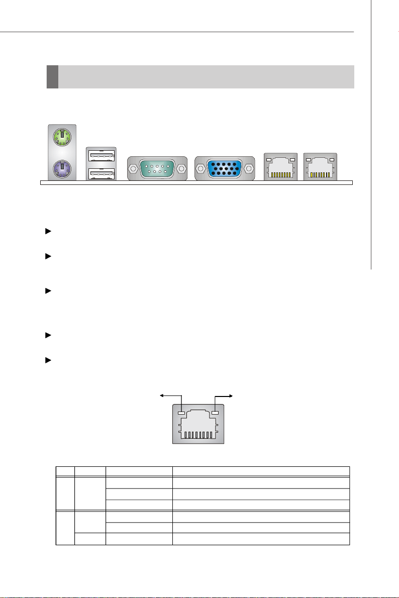
Back Panel
Mouse
USB Ports
Hardware Setup
Keyboard
VGA PortSerial Port LAN LAN
Mouse/Keyboard Connector
The standard PS/2® mouse/keyboard DIN connector is for a PS/2® mouse/keyboard.
USB Ports
The OHCI (Open Host Controller Interface) Universal Serial Bus root is for attaching
USB devices such as keyboard, mouse, or other USB-compatible devices.
Serial Port
The serial port is a 16550A high speed communications port that sends/ receives 16
bytes FIFOs. You can attach a serial mouse or other serial devices directly to the
connector.
VGA Port
The DB15-pin female connector is provided for VGA monitors.
RJ-45 LAN Jack
The standard RJ-45 jack is for connection to single Local Area Network (LAN). You
can connect a network cable to it.
Link Indicator
RJ-45 LAN Jack
LED Color LED State Condition
Off LAN link is not established.
Left Orange On (steady state) LAN link is established.
On (brighter & pulsing)The computer is communicating with another computer on the LAN.
Green Off 10 Mbit/sec data rate is selected.
Right On 100 Mbit/sec data rate is selected.
Orange On 1000 Mbit/sec data rate is selected.
Activity Indicator
2-7
Page 28
MS-9238 Server
Connectors
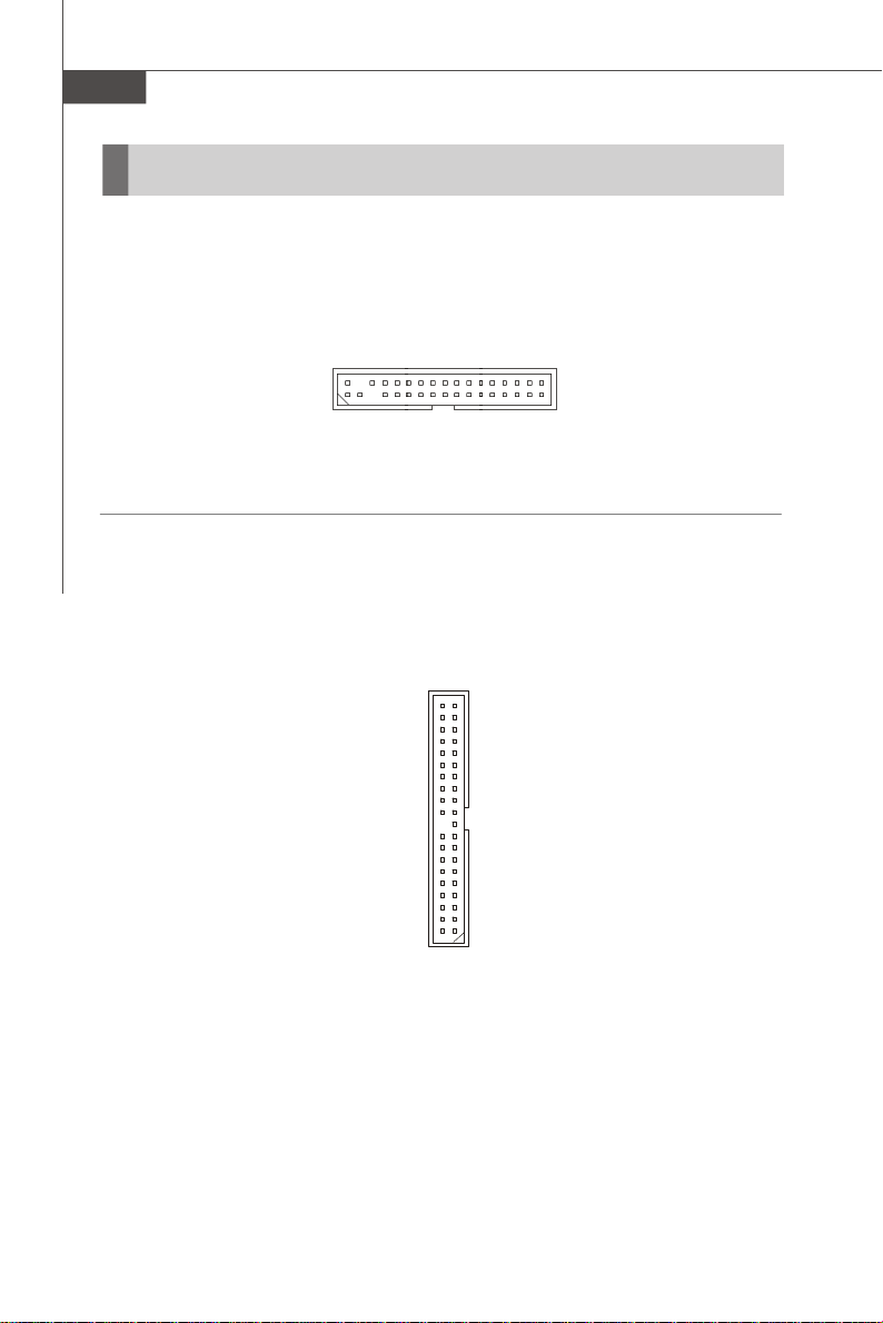
Floppy Disk Drive Connector: FDD1
The mainboard provides a standard floppy disk drive connector.
FDD1
ATA100 Hard Disk Connector: IDE1
The mainboard has a 32-bit Enhanced PCI IDE and Ultra DMA 66/100 controller that
provides PIO mode 0~4, Bus Master, and Ultra DMA 66/100 function. You can connect
hard disk drives, CD-ROM and other IDE devices.
2-8
IDE1
Page 29
Hardware Setup
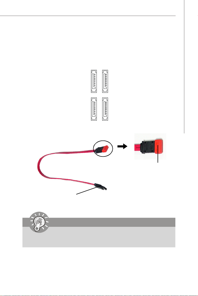
Serial ATA Connectors: SATA0 ~ SATA3
SATA0 ~ SATA3 are high-speed SATA II interface ports and support SATA II data rates
of 300MB/s. Each SATA II connector can connect to 1 hard disk device and is fully
compliant with Serial ATA 2.0 specifications.
Serial ATA cable
Connect to SATA connectors
Important
SATA1
SATA3
SATA0
SATA2
Take out the dust cover
and connect to the hard
disk devices
Please do not fold the Serial ATA cable into 90-degree angle. Otherwise,
data loss may occur during transmission.
2-9
Page 30

MS-9238 Server
Chassis Intrusion Switch Connector: JCI1
This connector connects to a 2-pin chassis switch. If the chassis is opened, the
switch will be short. The system will record this status and show a warning message on the screen. To clear the warning, you must enter the BIOS utility and clear the
record.
GND
1
2
CINTRU
JCI1
Fan Power Connectors: CPUFAN 1/2, SYSFAN 1/2/3/4/5/6
The fan power connectors support system cooling fan with +12V. When connecting
the wire to the connectors, always take note that the red wire is the positive and
should be connected to the +12V, the black wire is Ground and should be connected
to GND. If the mainboard has a System Hardware Monitor chipset onboard, you must
use a specially designed fan with speed sensor to take advantage of the CPU fan
control.
C
S
O
E
N
N
T
+
S
G
R
1
O
N
O
2
R
D
V
L
CPUFAN1/2
GND
+12V
SENSOR
SYSFAN1
SENSOR
GND
+12V
SYSFAN 2/3/4/5/6
2-10
Page 31

Hardware Setup
LAN LED Connectors: JACT1, JACT2
The LAN LED connectors are used to connect to LAN LEDs, which show the activity
of the LAN. The JACT1 is for the LAN 1 jack and the JACT2 is for the LAN2 jack. Both
LAN1 & LAN2 jacks are located on the back panel.
+ +
JACT2
JACT1
- -
Front Panel Connector: JFP1
The mainboard provides one front panel connector for electrical connection to the
front panel switches and LEDs. The JFP1 is compliant with Intel® Front Panel I/O
Connectivity Design Guide.
HDD
Reset
LED
Switch
-
-
+
+
JFP1
9
10
-
Power
Switch
1
2
+
Power
LED
JFP1 Pin Definition
PIN SIGNAL DESCRIPTION
1 HD_LED + Hard disk LED pull-up
2 FP PWR/SLP MSG LED pull-up
3 HD_LED - Hard disk active LED
4 FP PWR/SLP MSG LED pull-up
5 RST_SW - Reset Switch low reference pull-down to GND
6 PWR_SW + Power Switch high reference pull-up
7 RST_SW + Reset Switch high reference pull-up
8 PWR_SW - Power Switch low reference pull-down to GND
9 RSVD_DNU Reserved. Do not use.
2-11
Page 32

MS-9238 Server
Serial Port Connector: COM 2
The mainboard provides one 9-pin header as serial port COM 2. The port is a 16550A
high speed communication port that sends/receives 16 bytes FIFOs. You can attach
a serial mouse or other serial devices directly to it.
Pin Definition
1
9
COM 2
2
8
PIN SIGNAL DESCRIPTION
1 DCD Data Carry Detect
2 SIN Serial In or Receive Data
3 SOUT Serial Out or Transmit Data
4 DTR Data Terminal Ready
5 GND Ground
6 DSR Data Set Ready
7 RTS Request To Send
8 CTS Clear To Send
9 RI Ring Indicate
Front USB Connector: JUSB1, JUSB2
The mainboard provides two USB 2.0 pinheaders (optional USB 2.0 bracket available)
that are compliant with Intel® I/O Connectivity Design Guide. USB 2.0 technology
increases data transfer rate up to a maximum throughput of 480Mbps, which is 40
times faster than USB 1.1, and is ideal for connecting high-speed USB interface
peripherals such as USB HDD, digital cameras, MP3 players, printers, mo-
dems and the like.
JUSB1/2
1
2
10
9
Pin Definition
PIN SIGNAL PIN SIGNAL
1 VCC 2 VCC
3 USB0- 4 USB15 USB0+ 6 USB1+
7 GND 8 GND
9 Key (no pin) 10 USBOC
Important
Note that the pins of VCC and GND must be connected correctly to avoid
possible damage.
2-12
Page 33

Hardware Setup
Ultra320 SCSI Connector: SCSI1 (Optional)
SCSI (Small Computer System Interface) is a parallel interface standard for attaching
peripheral devices to computers. Ultra320 SCSI is the seventh generation of SCSI I/O
technology, and has a maximum data rate speed of 320 MB/sec. SCSI’s commitment
to backward compatibility and legacy support are the primary reasons for its durability as an I/O interface, making SCSI the industry standard for disk drive connection in
virtually all high-performance servers.
68-Pin Ultra320 SCSI Connector
Pin Description Pin Description
1 +DB(12) 35 -DB(12)
2 +DB(13) 36 -DB(13)
3 +DB(14) 37 -DB(14)
4 +DB(15) 38 -DB(15)
5 +DB(P1) 39 -DB(P1)
6 +DB(0) 40 -DB(0)
7 +DB(1) 41 -DB(1)
8 +DB(2) 42 -DB(2)
9 +DB(3) 43 -DB(3)
10 +DB(4) 44 -DB(4)
11 +DB(5) 45 -DB(5)
12 +DB(6) 46 -DB(6)
13 +DB(7) 47 -DB(7)
14 +DB(P) 48 -DB(P)
15 GROUND 49 GROUND
16 DIFFSENS 50 GROUND
17 TERMPWR 51 TERMPWR
18 TERMPWR 52 TERMPWR
19 RESERVED 53 RESERVED
20 GROUND 54 GROUND
21 +ATN 55 -ATN
22 GROUND 56 GROUND
23 +BSY 57 -BSY
24 +ACK 58 -ACK
25 +RST 59 -RST
26 +MSG 60 -MST
27 +SEL 61 -SEL
28 +C/D 62 -C/D
29 +REQ 63 -REQ
30 +I/O 64 -I/O
31 +DB(8) 65 -DB(8)
32 +DB(9) 66 -DB(9)
33 +DB(10) 67 -DB(10)
34 +DB(11) 68 -DB(11)
34
68
SCSI1
1
35
2-13
Page 34

MS-9238 Server
Jumpers
Clear CMOS Jumper: JBAT1
There is a CMOS RAM onboard that has a power supply from external battery to keep
the data of system configuration. With the CMOS RAM, the system can automatically
boot OS every time it is turned on. If you want to clear the system configuration, set
the JBAT1 (Clear CMOS Jumper ) to clear data.
JBAT1
1
3
Keep Data Clear Data
3
1
1
Important
To clear CMOS you should:
1. Short 1-2 pin while the system is off. Restart the PC and press F2 to enter
the BIOS Setup Utility. Shut down the PC.
2. Short 2-3 pin while the system is off. Restart the PC and press F2 to enter
the BIOS Setup Utility. Shut down the PC.
3. Short 1-2 pin while the system is off. Restart the PC.
Avoid clearing the CMOS while the system is on; it will damage the mainboard.
2-14
Page 35

Hardware Setup
BIOS Recovery Jumper: J9
Users can short connect pin#2-3 to recover the system BIOS. When the system is
done with the job, the buzzer will beep to remind users to set the jumper to its normal
state (pin#1-2 short connected).
J9
1
1 3
Normal
1 3
Recovery
BIOS Write Protect Jumper: JBIOS1
A "boot block" program is included as part of the system BIOS to recover the system
from a situation when the BIOS code is incorrect/corrupted or needs to be updated.
When the BIOS code is corrupted or needs to be updated, you have to at first disable
the write protect function by shorting 1-2 pin of the JBIOS1 jumper. Then the boot
block will try to recover the BIOS code, usually by reading it from a specially-prepared floppy disk.
Under normal operation, we suggest that you enable the write protect function by
shorting 2-3 pin of the JBIOS1 jumper to protect the boot block from virus infection.
1
3
1
JBIOS1
1
3
Disable Write Protect Enable Write Protect
LAN Jumper: JLANDIS1, JLANDIS2
These jumpers control the onboard LAN. The JLANDIS1 disables/enables the LAN1
jack while the JLANDIS2 disables/enables the LAN2 jack.
1
JLANDIS1
1
JLANDIS2
1
Enable LAN1
1
Enable LAN2
1
Disable LAN1
1
Disable LAN2
2-15
Page 36

MS-9238 Server
Slots
PCI (Peripheral Component Interconnect) Express Slot
This mainboard provides one PCI Express x8 slot.
PCI Express x8 Slot
Important
When adding or removing expansion cards, make sure that you unplug the
power supply first. Meanwhile, read the documentation for the expansion card
to configure any necessary hardware or software settings for the expansion
card, such as jumpers, switches or BIOS configuration.
2-16
Page 37

Hardware Setup
START
System Assembly Flowchart
The following flowchart shows basic system assembly procedures. Please note
that always wear anti-static gloves when handling electrical components and exercise caution during the installation process. For more information, contact your local
dealer or experienced technician.
REMOVE CHASSIS COVER
INSTALL
CPU & HEATSINK
INSTALL
MEMORY MODULES
REMOVE
RISER CARD BRACKET
INSTALL
RISER CARDS
2-17
Page 38

MS-9238 Server
REPLACE
RISER CARD BRACKET
INSTALL
HARD DISK DRIVES
CONNECT HDD
& POWER CORDS
2-18
CHECK IF ALL PARTS
ARE PROPERLY CONNECTED
REPLACE
CHASSIS COVER
FINISH
Page 39

Hardware Setup
System Assembly
Removing the Chassis Cover
1. Unscrew the chassis cover.
2. Press the release buttons and slide the chassis cover forwards.
3. Lift up the cover and remove it from
the chassis.
2-19
Page 40

MS-9238 Server
Replacing the Chassis Cover
1. Replace the chassis cover and slide it backwards.
2. Screw to secure the chassis cover.
Important
Before you remove or install any components, make sure the server is not
turned on or connected to the AC power.
2-20
Page 41

Hardware Setup
CPU, Heatsink, and Fan Duct
1. On top of the CPU is a fan duct designed to enhance heat dissipation of the CPU.
Lift up & remove the fan duct before installing the CPU.
2. Locate the first CPU socket. (The CPU has a plastic cap on it to protect the contact
from damage. Before installing the CPU, always cover it to protect the socket
pins.)
3. Remove the plastic cap from the load plate. The pins of the socket reveal.
CPU2
CPU1
4. Raise the load lever up to its full extent.5. Open the load plate.
2-21
Page 42

MS-9238 Server
6. After confirming the CPU direction (indicated below with red circles) for correct mating, put down
the CPU in the socket housing frame. Be sure to
grasp on the edge of the CPU base. Note that the
Alignment Key
alignment keys are matched.
7. Visually inspect if the CPU is seated well into the
socket. If not, take out the CPU with pure vertical
motion and reinstall.
Yellow triangle is the Pin 1 indicator
8. Cover the load plate onto the package.
9. Press down the load lever lightly onto the load plate and then secure the lever
with the hook under the retention tab.
10.Follow the same procedures to install
the second CPU.
Note: To install DUAL CPUs
on the board, you must use
the same types of CPUs
running at the same FSB
frequency.
2-22
Page 43

Hardware Setup
11.Place the heat sink on top of CPU1 and secure the screws on both sides.
Note: The heat sink has to be installed to prevent the CPU from overheating.
12.Follow the same procedures to install the second heatsink.
13.Replace the fan duct on top of the
heatsinks.
Note: To ensure proper cooling,
make sure the heat sinks & the fan
duct are properly installed.
2-23
Page 44

MS-9238 Server
Memory
1. Locate the DIMM slots on the mainboard. Insert the memory module vertically into
the DIMM slot. Then push it in until the golden finger on the memory module is
deeply inserted in the DIMM slot. The plastic clip at each side of the DIMM slot will
automatically close.
2. Follow the same procedures to install more memory modules if necessary.
2-24
Page 45

Memory Population Rules
Hardware Setup
FBD12
FBD11
FBD02
FBD01
Channel 1
Channel 0
Check the numbers of your DIMM modules and follow the population rules to install the
memory.
Numbers of DIMM Population Rules
1 DIMM Module FBD01
2 DIMM Modules <a> FBD01, FBD02
OR
<b> FBD01, FBD11
4 DIMM Modules FBD01, FBD02, FBD11, FBD12
Important
1. To enable successful system boot-up, always insert the memory modules
into the FBD01 first (Channel 0/ 1st).
2. In dual-channel mode, DIMM modules must be of the same type and density.
2-25
Page 46

MS-9238 Server
Expansion Card
1. Locate the riser card bracket and lift it up from the chassis.
2. Unscrew the cover plate and put it aside for later use.
2-26
Page 47

Hardware Setup
3. Insert the expansion card into the PCI-Express slot on the riser card.
4. Screw to secure the expansion card bracket.
5. Place the riser card bracket on top of the PCI-Express slot on the motherboard.
Align the riser card golden fingers with the PCI-Express slot.
6. Push the riser card bracket carefully down with even force on both sides.
2-27
Page 48

MS-9238 Server
Hard Disk Drive
1. To release the hot-swapping HDD tray, flip open the tray lever and pull the tray
out of the bay.
2. At the rear of the HDD are four screw holes, two on the right and two on the left
side. At the back of the HDD rack are four identical screw holes as on the HDD.
Place the HDD into the rack and align the screw holes on the HDD with the ones
on the rack. Secure the HDD with four screws supplied by the HDD vendor.
2-28
Page 49

3. Insert the HDD tray into the bay and
push the tray lever back in place.
Hardware Setup
2-29
Page 50

MS-9238 Server
Rack Mounting
1. Pull the inner channel out.
latch
Press the latch to
disconnect.
2. Assemble the inner rail to the chassis.
Fasten 6 screws at least to attach the inner channel onto the chassis.
2-30
M4 screw
Page 51

3. Mount the L-shaped bracket onto the outer channel.
Hardware Setup
FRONT
Use black round head
screws.
4. Mount the slides to the vertical racks.
Type A
M4 screw
Type B
M5 screw
BACK
black screw
shall be in flush position
washer
Type C
M5 screw
2-31
Page 52

MS-9238 Server
5. Insert the chassis into the frame.
2-32
Page 53

Chapter 3
BIOS Setup
This chapter provides information on the BIOS Setup
program and allows you to configure the system for
optimum use.
You may need to run the Setup program when:
² An error message appears on the screen during the
system booting up, and requests you to run SETUP.
² You want to change the default settings for cus-
tomized features.
BIOS Setup
3-1
Page 54

MS-9238 Server
Entering Setup
Power on the computer and the system will start POST (Power On Self Test) process.
When the message below appears on the screen, press <F2> key to enter Setup.
Press <F2> to enter SETUP
If the message disappears before you respond and you still wish to enter Setup,
restart the system by turning it OFF and On or pressing the RESET button. You may
also restart the system by simultaneously pressing <Ctrl>, <Alt>, and <Delete> keys.
Important
1.The items under each BIOS category described in this chapter are under
continuous update for better system performance. Therefore, the description may be slightly different from the latest BIOS and should be held for
reference only.
2.Upon boot-up, the 1st line appearing after the memory count is the BIOS
version. It is usually in the format:
3-2
P9238IMS V1.0 081506 where:
1st digit refers to BIOS maker as A = AMI, W = AWARD, and P =
PHOENIX.
2nd - 5th digit refers to the model number.
6th digit refers to the chipset as I = Intel, N = nVidia, and V = VIA.
7th - 8th digit refers to the customer as MS = all standard customers.
V1.0 refers to the BIOS version.
081506 refers to the date this BIOS was released.
Page 55

BIOS Setup
Control Keys
↑ ↓ Select Items
← Select Menus
Enter Select Sub-menus
Esc Exit
-/+ Change Values
F1 Help
<F9> Setup Defaults
<F10> Save and Exit
Getting Help
After entering the Setup menu, the first menu you will see is the Main Menu.
Main Menu
The main menu lists the setup functions you can make changes to. You can use the
arrow keys ( ↑↓ ) to select the item. The on-line description of the highlighted setup
function is displayed at the bottom of the screen.
Sub-Menu
If you find a right pointer symbol (as shown in the right view)
appears to the left of certain fields that means a sub-menu can
be launched from this field. A sub-menu contains additional options for a field parameter. You can use arrow keys ( ↑↓ ) to
highlight the field and press <Enter> to call up the sub-menu.
Then you can use the control keys to enter values and move
from field to field within a sub-menu. If you want to return to the main menu, just press
the <Esc >.
General Help <F1>
The BIOS setup program provides a General Help screen. You can call up this screen
from any menu by simply pressing <F1>. The Help screen lists the appropriate keys
to use and the possible selections for the highlighted item. Press <Esc> to exit the
Help screen.
3-3
Page 56

MS-9238 Server
The Menu Bar
Main
Use this menu for basic system configurations, such as time, date etc.
Advanced
Use this menu to set up the items of special enhanced features available on your
system’s chipset.
Security
Use this menu to set Supervisor and User Passwords.
Power
Use this menu to specify your settings for power management.
PC Health
This entry monitors your hardware health status.
Boot
Use this menu to specify the priority of boot devices.
Exit
This menu allows you to load the BIOS default values or factory default settings into
the BIOS and exit the BIOS setup utility with or without changes.
3-4
Page 57

Main
System Time (hh:mm:ss)
The time format is <Hour> <Minute> <Second>.
BIOS Setup
System Date (mm:dd:yy)
The date format is <Month> <Date> <Year>.
Legacy Diskette A
This setting allows you to set the type of floppy drives installed.
IDE Channel 0 Master/Slave, SATA Port 1/2/3/4
[Type] Press <+> or <-> to select [Manual], [None] or
[Auto] type. Note that the specifications of
your drive must match with the drive table.
The hard disk will not work properly if you
enter improper information for this category.
If your hard disk drive type is not matched or
listed, you can use [Manual] to define your
own drive type manually.
[Multi-Sector Transfers] Any selection except Disabled determines
the number of sectors transferred per block
[LBA Mode Control] Enabling LBA causes Logical Block Ad-
dressing to be used in place of Cylinders,
Heads and Sectors
[32-Bit I/O] Enables 32-bit communication between
CPU and IDE card
3-5
Page 58

MS-9238 Server
[Tranfer Mode] Selects the method for transferring the data
[Ultra DMA Mode] Indicates the type of Ultra DMA
Boot Features
The sub-menu is used to configure system boot-up features.
Floppy Check
This setting causes the BIOS to search for floppy disk drives at boot time. When
enabled, the BIOS will activate the floppy disk drives during the boot process.
The drive activity light will come on and the head will move back and forth once.
Summary Screen
Selecting [Enabled] displays system summary screen during boot up.
between the hard disk and system memory
QuickBoot Mode
Setting the item to [Enabled] allows the system to boot within 5 seconds since
it will skip some check items.
3-6
Page 59

System Information
Press <Enter> to view the hardware specifications of your system.
System Memory, Extended Memory
These items show the memory status of the system. (Read-only)
BIOS Setup
3-7
Page 60

MS-9238 Server
Advanced
Reset Configuration Data
Select [Yes] if you want to clear the Extended System configuration Data (ESCD)
area.
Large Disk Access Mode
Defaulting this setting to [DOS] will create a Translated FDPT. Compatible ill-behaved
applications will operate correctly when [DOS] is selected. Setting to [Other] will
create a Standard FDPT. Incompatible ill-behaved applications will function correctly
with [Other].
3-8
Page 61

BIOS Setup
Advanced Chipset Control
Press <Enter> to enter the sub-menu and the following screen appears:
USB Host Controller
This setting disables/enables the onboard USB host controller.
IOAT Support
This field enables Intel I/O Acceleration Technology which transfers data more
efficiently.
ECC Function Support
This setting supports Single bit / None ECC (Error Correction Code) checking, a
method of checking the integrity of data in DRAM.
Memory Branch Mode
This setting determines the memory branch mode. Setting to [Sequential] or
[Interleave] depending on your needs.
Parallel ATAA
This setting allows you to enable or disable the onchip Parallel-ATA controller.
Serial ATAA
This setting allows you to enable or disable the onchip Serial-ATA controller.
SATA Controller Mode Option
This setting specifies SATA controller mode. Please note that Pre-Win2K
OS’s do not work in Enhanced mode.
[Compatible] SATA and PATA drives are auto-detected and placed
in Legacy mode.
3-9
Page 62

MS-9238 Server
[Enhanced] SATA and PATA drives are auto-detected and placed
SATA RAID Enable
This feature allows users to enable or disable the RAID function for each
SATA hard disk drive.
SATA AHCI Enable
This setting disables/enables Enhanced AHCI mode.
SATA RAID & AHCI Enable (for Adaptec SATA RAID Option ROM)
If this setting is set to [Enabled] and the SATA RAID function is not configured,
only AHCI mode will be supported.
(non-AHCI) in Native IDE mode.
3-10
Page 63

BIOS Setup
Advanced Processor Options
Press <Enter> to enter the sub-menu and the following screen appears:
Hyperthreading (auto detect function for Intel Dempsey CPU)
The processor uses Hyper-Threading technology to increase transaction rates
and reduces end-user response times. The technology treats the two cores
inside the processor as two logical processors that can execute instructions
simultaneously. In this way, the system performance is highly improved. If you
disable the function, the processor will use only one core to execute the
instructions. Please disable this item if your operating system doesn’t
support 4-way processors & the system with 2 HT processors, or
unreliability and instability may occur.
Important
Enabling the functionality of Hyper-Threading Technology for your
computer system requires ALL of the following platform Components:
*CPU: Intel® Pentium® 4 or Xeon™ Processors with HT Technology;
*Chipset: Intel® Chipsets that support HT Technology;
*BIOS: A BIOS that supports HT Technology and has it enabled;
*OS: An operating system that supports HT Technology.
For more information on Hyper-threading Technology, go to:
http:/ /www.int e l.co m /inf o/h y pert hre ading
Intel Virtualization Technology
Virtualization enhanced by Intel Virtualization Technology will allow a platform
to run multiple operating systems and applications in independent partitions.
With virtualization, one computer system can function as multiple “virtual” systems.
3-11
Page 64

MS-9238 Server
Thermal Management 2 (auto detect function)
This setting specifies the thermal technologies implemented in the Intel® processor.
C1 Enhanced Mode
This item allows you to enable/disable the C1E power management feature
which can drop clock speed and voltage on the processor.
Execute Disable Bit
Intel's Execute Disable Bit functionality can prevent certain classes of malicious
"buffer overflow" attacks when combined with a supporting operating system.
This functionality allows the processor to classify areas in memory by where
application code can execute and where it cannot. When a malicious worm
attempts to insert code in the buffer, the processor disables code execution,
preventing damage or worm propagation.
Discrete MTRR Allocation
If the system has 4GB of memory or greater, Discrete MTRR Allocation must be
enabled in the BIOS Memory Cache section. Otherwise, system performance
will be affected.
I/O Device Configuration
Press <Enter> to enter the sub-menu and the following screen appears:
Serial Port A/B
This is used to enable or disable the onboard serial port A/B.
Base I/O Address
These items specify the base I/O addresses of the onboard serial port A/B.
Interrupt
These field allows you to select IRQ Resources for serial port A/B.
3-12
Page 65

BIOS Setup
Floppy Disk Controller
Select [Enabled] if your system has a floppy disk controller (FDD) installed on
the system board and you wish to use it. If you install add-on FDC or the system
has no floppy drive, select [Disabled] in this field.
Onboard Device Control
Press <Enter> to enter the sub-menu and the following screen appears:
LAN Option ROM Scan
Use this feature to initialize device expansion ROM.
Onboard SCSI (auto detect function)
This setting allows you to enable/disable the onboard SCSI device.
3-13
Page 66

MS-9238 Server
Console Redirection
Com Port Address
This setting enables/disables the Com port address for console connection.
Baud Rate
This setting specifies the transfer rate (bits per second) of Console Redirection.
Console Type
This setting specifies the console type.
Flow Control
This feature allows you to enable flow control.
Console Connection
This feature indicates whether the console is connected directly to the system
or a modem is used for connection.
Continue C. R. after POST
Selecting [On] will enable Console Redirection after OS has loaded.
3-14
Page 67

BIOS Setup
DMI Event Logging
Press <Enter> to enter the sub-menu and the following screen appears:
Event log validity/capacity
These items indicate the status of Event log validity and capacity.
View DMI event log
These item allows you to view the content of the DMI event log.
Event Logging
This function is used to log DMI events.
ECC Event Logging
This function is used to log ECC events.
Mark DMI events as readd
This field allows you to mark DMI events as read.
Clear all DMI event logs
This function is used to clear all DMI event logs.
Legacy USB Support
Set to [Enabled] if you need to use any USB 1.1/2.0 device in the operating system
that does not support or have any USB 1.1/2.0 driver installed, such as DOS and SCO
Unix. Set to [Disabled] only if you want to use any USB device other than the USB
mouse.
Option ROM Placement
This setting determines the Option ROM placement. If the system hangs during boot,
please restart the system and enter the BIOS Setup Utility to change this setting.
3-15
Page 68

MS-9238 Server
Security
Supervisor Password Is, User Password Is
These items indicate the status of password settings.
Set Supervisor Password
Supervisor Password controls access to the BIOS Setup utility.
Set User Password
User Password controls access to the system at boot.
Password on Boot
Choosing [Enabled] requires a password on boot. It requires prior setting of the
supervisor password. If the supervisor password is set and this option is disabled,
BIOS assumes the user is booting.
Chassis Intrusion
The field enables or disables the feature of recording the chassis intrusion status
and issuing a warning message if the chassis is once opened.
Reset Chassis Intrusion
The field is used to clear the chassis intrusion warning message.
3-16
Page 69

Power
BIOS Setup
Important
S3-related functions are available only when your BIOS supports S3 sleep mode.
Power Button Function
This feature allows users to configure the power button function. Settings are:
[Instant-Off] The power button functions as a normal power-on/-off
[Delay 4 Second]When you press the power button, the computer enters
Wake On LAN/PME
The item specifies how the system will be awakened from power saving mode when
input signal of the LAN/PME is detected.
After Power Failure
This setting specifies whether your system will reboot after a power failure or
interrupt occurs. Available settings are:
[Stay Off] Returns the system to an off state.
[Power On] Returns the system to a full on state.
button.
the suspend/sleep mode, but if the button is pressed for
more than four seconds, the computer is turned off.
3-17
Page 70

MS-9238 Server
[Last State] Restores the system to the previous status before power
Resume On Modem Ring
The item specifies how the system will be awakened from power saving mode when
input signal of the Modem Ring is detected.
Resume On Time
Select [On] to wake up the system at predetermined time.
Resume Time
The time format is <HH> <MM> <SS>.
failure or interrupt occurred.
3-18
Page 71

BIOS Setup
PC Health
Fan & Temperature Menu
These items display the current temperatures and fans’ speeds of the system.
Auto FAN Speed Control
This item enables/disables the Smart Fan feature (SFAN1 & SFAN4 excluded). Smart
Fan is an excellent feature which will adjust the CPU and system fan speed automatically depending on the current CPU and system temperature, avoiding the overheating to damage your system.
3-19
Page 72

MS-9238 Server
CPU1 Target Temp, CPU2 Target Temp
You can select a fan value here. If the current temperature reaches to the minimum
threshold you set here, the fan will slow down to keep the temperature stable.
CPU1 Therm Temp Limit, CPU2 Therm Temp Limit
You can select a fan tolerance value here. If the current temperature of the fan
reaches to the maximum threshold you set here, the fan will speed up for cooling
down.
CPU1 Volt., CPU2 Volt., +3.3V, +5V, +12V, -12V, Vbat
These items display the current voltages of the system.
3-20
Page 73

BIOS Setup
Boot
These settings allow users to set the priority of the specified devices.You may use
the arrow keys ( ↑↓ ) to select the desired device, <+>/<-> key to move it up/down
in the priority list, <x> key to exclude or include the device to boot, (Shift + 1) to enable
or disable a device, (1 - 4) keys to load default boot sequence.
3-21
Page 74

MS-9238 Server
Exit
Exit Saving Changes
Save changes to CMOS and exit setup.
Exit Discarding Changes
Abandon all changes and exit setup.
Load Setup Defaults
Use this menu to load the default values set by the BIOS vendor for stable system
performance.
Discard Changes
Abandon all changes.
Save Changes
Save changes to CMOS.
3-22
Page 75

Intel SATA RAID
Appendix A
Intel SATA RAID (Optional)
The Southbridge provides a hybrid solution that combines four independent SATAII ports for support of up
to four Serial ATAII (Serial ATAII RAID) drives.
It offers RAID level 0 (Striping), RAID level 1 (Mirroring
and Duplexing), RAID level 5 (Block Interleaved Distributed Parity), RAID level 10 (A Stripe of Mirrors) and
Intel® Martix Storage Technology.
Important
For installing the Intel® Application Accelerator RAID in windows 2003, you can go to http://support.intel.com/support/
chipsets/iaa_raid/sb/cs-009333.htm.
The user’s manual herein will show you how to properly configure
your system when using the IAA Edition.
A-1
Page 76

MS-9238 Server
Introduction
The Southbridge provides a hybrid solution that combines four independent SATAII
ports for support of up to four SATAII drives.
Serial ATAII (SATAII) is the latest generation of the ATA interface. SATA hard drives
deliver blistering transfer speeds up to 300MB/sec. Serial ATA uses long, thin cables,
making it easier to connect your drive and improving the airflow inside your PC. The
most outstanding features are:
1. Supports 300MB/s transfers with CRC error checking.
2. Supports Hot-plug-n-play feature.
3. Data handling optimizations including tagged command queuing, elevator
seek and packet chain command.
The Intel® Southbridge offers RAID level 0 (Striping), RAID level 1 (Mirroring and
Duplexing), RAID level 5 (Block Interleaved Distributed Parity), RAID level 10 (A Stripe
of Mirrors) and Intel® Martix Storage Technology.
RAID 0 breaks the data into blocks which are written to separate hard drives. Spreading
the hard drive I/O load across independent channels greatly improves I/O performance.
RAID 1 provides data redundancy by mirroring data between the hard drives and
provides enhanced read performance. RAID 5 Provides data striping at the byte level
and also stripe error correction information. This results in excellent performance
and good fault tolerance. Level 5 is one of the most popular implementations of RAID.
RAID 10 Not one of the original RAID levels, multiple RAID 1 mirrors are created, and
a RAID 0 stripe is created over these. Intel Matrix RAID Technology is the advanced
ability for two RAID volumes to share the combined space of two hard drives being
used in unison.
Important
1. The least number of hard drives for RAID 0, RAID 1 or Matrix mode is 2.
The least number of hard drives for RAID 10 mode is 4. And the maximum
number of hard drives for RAID 5 mode is 3.
2. All the information/volumes listed in your system might differ from the
illustrations in this appendix.
3. RAID support on Linux OS will be changed by vendors. Please contact
MSI Sales if you need SATA RAID support on Linux OS.
A-2
Page 77

Intel SATA RAID
BIOS Configuration
The Intel Matrix Storage Manager Option ROM should be integrated with the system
BIOS on all motherboards with a supported Intel chipset. The Intel Matrix Stroage
Manager Option ROM is the Intel RAID implementation and provides BIOS and DOS
disk services. Please use <Ctrl> + <I> keys to enter the “Intel(R) RAID for Serial ATA”
status screen, which should appear early in system boot-up, during the POST
(Power-On Self Test). Also, you need to enable the RAID function in BIOS to create,
delete and reset RAID volumes.
Using the Intel Matrix Stroage Manager Option ROM
1. Creating, Deleting and Resetting RAID Volumes:
The Serial ATA RAID volume may be configured using the RAID Configuration utility
stored within the Intel RAID Option ROM. During the Power-On Self Test (POST), the
following message will appear for a few seconds:
Important
The “Driver Model”, “Serial #” and “Size” in the following example might be
different from your system.
6
After the above message shows, press <Ctrl> and <I> keys simultaneously to enter
the RAID Configuration Utility.
6.2.1002 ESB2
Important
The following procedure is only available with a newly-built system or if you
are reinstalling your OS. It should not be used to migrate an existing system
to RAID.
A-3
Page 78

MS-9238 Server
After pressing the <Ctrl> and <I> keys simultaneously, the following window will
appear:
6
6.2.1002 ESB2
(1) Create RAID Volume
1. Select option 1 “Create RAID Volume” and press <Enter> key. The following
screen appears. Then in the Name field, specify a RAID Volume name and
then press the <TAB> or <Enter> key to go to the next field.
2. Use the arrow keys to select the RAID level best suited to your usage model
in RAID Level.
A-4
6
6.2.1002 ESB2
Page 79

Intel SATA RAID
3. In the Disk field, press <Enter> key and the following screen appears. Use
<Space> key to select the disks you want to create for the RAID volume, then
click <Enter> key to finish selection.
6
6.2.1002 ESB2
4. Then select the strip value for the RAID array by using the “upper arrow” or
“down arrow” keys to scroll through the available values, and pressing the
<Enter> key to select and advance to the next field. The available values
range from 4KB to 128 KB in power of 2 increments. The strip value should be
chosen based on the planned drive usage. Here are some typical values:
RAID0 – 128KB
RAID10 – 128KB
RAID5 – 64KB
5. Then select the capacity of the volume in the Capacity field. The default
value is the maximum volume capacity of the selected disks.
6
6.2.1002 ESB2
A-5
Page 80

MS-9238 Server
Important
Since you want to create two volumes (Intel Matrix RAID Technology), this
default size (maximum) needs to be reduced. Type in a new size for the first
volume. As an example: if you want the first volume to span the first half of the
two disks, re-type the size to be half of what is shown by default. The second
volume, when created, will automatically span the remainder of two hard
drives.
6.Then the following screen appears for you to confirm if you are sure to
create the RAID volume. Press <Y> to continue.
6
6.2.1002 ESB2
7.Then the following screen appears to indicate that the creation is finished.
6
6.2.1002 ESB2
A-6
Page 81

Intel SATA RAID
(2) Delete RAID Volume
Here you can delete the RAID volume, but please be noted that all data on RAID
drives will be lost.
Important
If your system currently boots to RAID and you delete the RAID volume in the
Intel RAID Option ROM, your system will become unbootable.
Select option 2 Delete RAID Volume from the main menu window and press
<Enter> key to select a RAID volume for deletion. Then press <Delete> key to
delete the selected RAID volume. The following screen appears.
6
Press <Y> key to accept the volume deletion.
6.2.1002 ESB2
A-7
Page 82

MS-9238 Server
(3) Reset Disks to Non-RAID
Select option 3 Reset Disks to Non-RAID and press <Enter> to delete the RAID
volume and remove any RAID structures from the drives. The following screen
appears:
6
6.2.1002 ESB2
Press <Y> key to accept the selection.
Important
1. You will lose all data on the RAID drives and any internal RAID structures
when you perform this operation.
2. Possible reasons to ‘Reset Disks to Non-RAID’ could include issues such
as incompatible RAID configurations or a failed volume or failed disk.
A-8
Page 83

Adaptec SATA RAID
Appendix B
Adaptec SATA RAID (Optional)
The Southbridge provides a hybrid solution that combines four independent SATAII ports for support of up
to four Serial ATAII (Serial ATAII RAID) drives.
It offers RAID level 0 (Striping), RAID level 1 (Mirroring
and Duplexing) and RAID level 10 (A Stripe of Mirrors).
B-1
Page 84

MS-9238 Server
Introduction
The Southbridge provides a hybrid solution that combines four independent SATAII
ports for support of up to four SATAII drives.
Serial ATAII (SATAII) is the latest generation of the ATA interface. SATA hard drives
deliver blistering transfer speeds up to 300MB/sec. Serial ATA uses long, thin cables,
making it easier to connect your drive and improving the airflow inside your PC. The
most outstanding features are:
1. Supports 300MB/s transfers with CRC error checking.
2. Supports Hot-plug-n-play feature.
3. Data handling optimizations including tagged command queuing, elevator seek
and packet chain command.
The Intel Southbridge offers RAID level 0 (Striping), RAID level 1 (Mirroring and
Duplexing) and RAID level 10 (A Stripeof Mirrors).
RAID 0 breaks the data into blocks which are written to separate hard drives. Spreading
the hard drive I/O load across independent channels greatly improves I/O performance.
RAID 1 provides data redundancy by mirroring data between the hard drives and
provides enhanced read performance.
RAID 10 Not one of the original RAID levels, multiple RAID 1 mirrors are created, and
a RAID 0 stripe is created over these. Intel Matrix RAID Technology is the advanced
ability for two RAID volumes to share the combined space of two hard drives being
used in unison.
Important
1. The least number of hard drives for RAID 0 or RAID 1 is 2. The least
number of hard drives for RAID 10 mode is 4.
2. All the information/volumes listed in your system might differ from the
illustrations in this appendix.
3. When installing SuSE OS under SATA RAID & AHCI mode, once the OS
boots from the CD-ROM, select F3 or F5 as requested to add drivers.
Then toggle to “ Installation” and, at the command prompt, type
“broken_modules=ahci”
4. RAID support on Linux OS will be changed by vendors. Please contact
MSI Sales if you need SATA RAID support on Linux OS.
B-2
Page 85

Adaptec SATA RAID
BIOS Configuration
The Adaptec SATA Option ROM should be integrated with the system BIOS on all
motherboards with a supported Intel chipset. The Adaptec Option ROM is the Adaptec
RAID implementation and provides BIOS and DOS disk services. Please use <Ctrl> +
<A> keys to enter the “Adaptec Embedded SATA HostRAID” status screen, which
should appear early in system boot-up, during the POST(Power-On Self Test). Also,
you need to enable the RAID function in BIOS to create, delete and reset RAID
volumes.
Using the Adaptec SATA HostRAID Option ROM
Creating and Deleting RAID Volumes:
The Serial ATA RAID volume may be configured using the RAID Configuration utility
stored within the Adaptec RAID Option ROM. During the Power-On Self Test (POST),
the following message will appear for a few seconds:
Important
The “Driver Model”, “Serial #” and “Size” in the following example might be
different from your system.
After the above message shows, press <Ctrl> and <A> keys simultaneously to enter
the RAID Configuration Utility.
Important
The following procedure is only available with a newly-built system or if you
are reinstalling your OS. It should not be used to migrate an existing system
to RAID.
B-3
Page 86

MS-9238 Server
After pressing the <Ctrl> and <A> keys simultaneously, the following window will
appear:
(1) Create RAID Volume
1. Enter Array Configuration Utility. Select option “Create array” and press
<Enter> key. The following screen appears.
B-4
Page 87

Adaptec SATA RAID
Then in the Select drivers to create Array field, specify the devices and
then press the <Enter> key to go to the next field.
2. Use the arrow keys to select the RAID level best suited to your usage model
in RAID Level.
B-5
Page 88

MS-9238 Server
3. Then Enter the Array Label name, and pressing the <Enter> key to select and
advance to the next field. The available values range from 16KB to 64 KB in
power of 2 increments. The strip value should be chosen based on the
planned drive usage. Here are some typical values:
RAID0 – 64KB
RAID10 – 64KB
4. Then select the Create RAID via Quick Init, and select [Done] to finish the
creation.
B-6
Page 89

Adaptec SATA RAID
5. Enter Manager Arrays to confirm if the creation is finished.
B-7
Page 90

MS-9238 Server
(2) Delete RAID Volume
Here you can delete the RAID volume, but please be noted that all data on RAID
drives will be lost.
Important
If your system currently boots to RAID and you delete the RAID volume in the
Adaptec RAID Option ROM, your system will become unbootable.
Select option Manager Arrays from the main menu window and press <Enter>
key to select a RAID volume for deletion. Then press <Delete> key to delete the
selected RAID volume. The following screen appears.
B-8
Page 91

Adaptec SATA RAID
Select [Delete], and press <Enter>. The following screen appears:
Press <Y> key to accept the volume deletion.
B-9
Page 92

MS-9238 Server
B-10
Page 93

Appendix C
SCSI BIOS (Optional)
This chapter provides information on the Small Computer System Interface (SCSI) BIOS setup utility and
allows you to configure the SCSI subsystem for optimum use.
You may need to run the SCSI BIOS setup utility when:
² You want to change the default SCSI controller set-
tings for customized features.
² You intend to manage any of the attached SCSI
devices.
SCSI BIOS
C-1
Page 94

MS-9238 Server
Exit the menu or return to the main menu from
Entering SCSI BIOS
Power on the computer and the system will start POST (Power On Self Test) process.
When the message below appears on the screen, press <Ctrl> + <A> keys simultaneously to enter SCSI BIOS utility.
vvv Press <Ctrl><A> for SCSISelect(TM) Utility www
Control Keys
Use the following keys to navigate the SCSI BIOS menu items.
<↑> <↓> <←> <→>
<Enter> Select the item or show the options of the
<Esc>
<F6> Restore the default SCSI values
Move between different items
selected item
a submenu
Selecting the SCSI Channel
After entering the SCSI BIOS by pressing the <Ctrl> + <A> key combination, you will
see the following menu appear on the screen.
AIC-7901 at slot 00, 05:05:00
C-2
Page 95

SCSI BIOS
Selecting the Management Type
The following screen will appear after you select the SCSI channel you intend to
manage. The menu will list two categories for you to choose what to do with the SCSI
channel. Move the cursor to the desired function and press <Enter>.
Configure/View SCSI Controller Settings
Use this option for SCSI controller configurations.
Configure/View HostRAID Settings
Use this option for HostRAID configurations.
SCSI Disk Utilities
Use this option to manage the attached SCSI device.
C-3
Page 96

MS-9238 Server
Configure/View SCSI Controller Settings
There are 8 items in the “Configure/View SCSI Controller Settings ” screen. These
items display or allow you to change the SCSI controller’s settings. Use the arrow
keys to highlight the item and then press <Enter> to select the value you want in each
item or enter each item’s sub-menu screen.
AIC-7901 at slot 00, 05:05:00
Configuration
SCSI Bus Interface Definitions
SCSI Controller ID....................................7
SCSI Controller Parity.............................Enabled
SCSI Controller Termination..................Enabled
Additional Options
Boot Device Configuration.....................Press <Enter>
SCSI Device Configuration......................Press <Enter>
Advanced Configuration..........................Press <Enter>
HostRAID...................................................Enabled
BIOS Information
Interrupt (IRQ) Channel..........................11
I/O Port Address........................................B000h, B400h
<F6> -- Reset to SCSI Controller Defaults
SCSI Bus Interface Definitions
SCSI Controller ID
The item is used to assign a SCSI ID to the SCSI controller. It is recommended that you
should leave the default setting unchanged.
SCSI Controller Parity
Use the field to enable or disable SCSI parity error checking function. If any of your
SCSI devices does not support parity checking, disable this function. While disabling
the function, you should disable disconnections for all devices, as parity checking for
the reselection phase is NOT disabled. A non-parity device’s I/O operation will never
complete if the reselection fails due to a parity error.
SCSI Controller Termination
In order to have the SCSI bus function properly and reliably, termination at the ends of
the SCSI bus is necessary. Proper termination can ensure signal on the SCSI bus will
not reflect and cause data loss or errors.
C-4
Page 97

SCSI BIOS
Additional Options
Boot Device Configuration
Press <Enter> to enter the sub-menu screen.
Boot Device Configuration
Single Image
Master SCSI Controller....................AIC-7901 at slot 07 03:07:00
Select SCSI peripheral from which to boot
Boot SCSI Controller.........................AIC-7901 at slot 07 03:07:00
Boot SCSI ID.......................................0
Option Listed Below Has NO EFFECT if MULTI LUN Support is Disabled
Boot LUN Number...........................0
Boot SCSI Controllers
Select SCSI channel AIC-7901 to boot up the SCSI subsystem.
Boot SCSI ID
Specify a SCSI device to become the boot device by selecting its SCSI ID.
Boot LUN Number
If a boot device has multiple logical units, you must specify the boot logical unit
number (LUN). If multiple LUN support is disabled, specifying a number here is
useless.
C-5
Page 98

MS-9238 Server
SCSI Device Configuration
Press <Enter> and the following sub-menu screen appears. The sub-menu screen
allows you to specify the configuration for each device on the SCSI bus.
SCSI Device Configuration
SCSI Device ID #0 #1 #2 #3 #4 #5 #6 #7
Sync Transfer Rate (MB/Sec).......320 320 320 320 320 320 320 320
Packetized......................................YesYes Yes Yes Yes Yes Yes Yes
QAS................................................YesYes Yes Yes Yes Yes Yes Yes
Initiate Wide Negotiation..............Yes Yes Yes Yes Yes Yes Yes Yes
Enable Disconnection......................Yes Yes Yes Yes Yes Yes Yes Yes
Send Start Unit Command...........Yes Yes Yes Yes Yes Yes Yes Yes
BIOS Multiple LUN Support.......No No No No No No No No
Include in BIOS Scan......................Yes Yes Yes Yes Yes Yes Yes Yes
SCSI Device ID #8 #9 #10#11#12#13#14#15
Sync Transfer Rate (MB/Sec).......320 320 320 320 320 320 320 320
Packetized..................................... YesYes Yes Yes Yes Yes Yes Yes
QAS................................................YesYes Yes Yes Yes Yes Yes Yes
Initiate Wide Negotiation..............Yes Yes Yes Yes Yes Yes Yes Yes
Enable Disconnection......................Yes Yes Yes Yes Yes Yes Yes Yes
Send Start Unit Command...........Yes Yes Yes Yes Yes Yes Yes Yes
BIOS Multiple LUN Support.......No No No No No No No No
Include in BIOS Scan......................Yes Yes Yes Yes Yes Yes Yes Yes
Sync Transfer Rate (MB/Sec)
The field allows you to specify the maximum synchronous data transfer rate
depending on the type of each SCSI device. Select [ASYN] to enable asynchronous negotiation for some older SCSI devices.
Packetized
When enabled, this option is supported by the device drivers. However, this
option is not supported by the BIOS.
QAS
When enabled, this option is supported by the device drivers. However, this
option is not supported by the BIOS.
Initiate Wide Negotiation
When set to [Yes], the field allows wide SCSI hard drives to use 16-bit (2 bytes)
transfers.
Enable Disconnection
This field tells the SCSI controller whether or not to allow the specified SCSI
device to disconnect during an I/O transfer operation. The disconnection ability
frees the SCSI bus to allow other I/O processes and thus optimizes the SCSI
bus performance.
C-6
Page 99

SCSI BIOS
Send Start Unit Command
When set to Yes, the SCSI controller sends the Start Unit command to the
specified SCSI device during bootup. The interface powers up the SCSI device
on-at-a-time during bootup, reducing the load on the computer’s power supply.
BIOS Multiple LUN Support
Select Yes when any SCSI device has multiple logical units.
Include in BIOS Scan
Selecting [Yes] allows the SCSI controller to control the SCSI device with its
SCSI ID. When set to [No], the SCSI controller does not control the specified
SCSI device by not scanning for the SCSI ID during bootup, but the boot time will
be decreased.
Advanced Configuration
Press <Enter> to enter the sub-menu screen for advanced configuration.
Advanced Configuration
Reset SCSI Bus at IC Initialization...................................................Enabled
Display <Ctrl><A> Message During BIOS Initialization.........Enabled
Extended Int 13 Translation for DOS Drives > 1 GByte............Enabled
POST Display Mode.............................................................................Verbose
SCSI Controller Int 13 Support.........................................................Enabled
Option Listed Below Has NO EFFECT if MULTI LUN Support is Disabled
Domain Validation................................................................................Enabled
Support Removable Disks Under Int 13 as Fixed Disks...........Disabled
BIOS Support for Bootable CD-ROM.............................................Enabled
Reset SCSI Bus at IC Initialization
Selecting Enabled will reset the SCSI bus the first time the SCSI controller is
initialized.
Display <Ctrl><A> Message During BIOS Initialization
When enabled, the message “ Press <Ctrl><A> for SCSISelect(TM) Utility” appears on the screen during bootup. If disabled, the message does not show up,
but you can still press <Ctrl> + <A> key combination to enter the SCSI BIOS
utility.
Extended Int 13 Translation for DOS Drives > 1 GByte
The field allows SCSI hard disk drives greater than 1 GB to use a translation
scheme of 255 heads, 63 sectors per track.
C-7
Page 100

MS-9238 Server
POST Display Mode
The field determines how much information about your SCSI controller and
devices appear on the screen during bootup. For the most complete information,
choose [Diagnostic]. For a faster boot, select [Silent].
SCSI Controller Int 13 Support
The field allows you to enable or disable the support for Int 13h. The software
interrupt “Int 13h” is the interface through which the operating system or application is able to pass commands to hard disk drives, such as reading, writing
and formatting.
Domain Validation
When enabled, these options are available if they are implemented in the device
drivers. However, this option is not supported by the BIOS.
Support Removable Disks Under Int13 as Fixed Disks
When [Boot Only] is selected, only the removable media drive designated as the
boot device will be treated as a hard disk drive. When [All Disks] is selected, all
removable media drives supported by the BIOS are treated as hard disk drives.
If selecting [Disabled], no removable media drive is treated as a hard disk drive
and the removable media drives must be controlled by the OS drivers.
BIOS Support for Bootable CD-ROM
When enabled, the SCSI controller BIOS supports bootable CD-ROM under the
El Torito specification. If booting from a hard disk or other device, make sure no
bootable CD-ROM is inserted or disable this option.
BIOS Information
Interrupt (IRQ) Channel
Displays the IRQ line assigned to the SCSI channel.
I/O Port Address
Displays the I/O port address assigned to the SCSI channel.
C-8
 Loading...