

Page 1
X2-106 Series
MS-9272 1U Rackmount Server
G52-92721X1
i
Page 2

Copyright Notice
The material in this document is the intellectual property of MICRO-STAR
INTERNATIONAL. We take every care in the preparation of this document, but no
guarantee is given as to the correctness of its contents. Our products are under
continual improvement and we reserve the right to make changes without notice.
Trademarks
All trademarks are the properties of their respective owners.
Intel® and Pentium® are registered trademarks of Intel Corporation.
AMD, Athlon™, Athlon™ XP, Thoroughbred™, and Duron™ are registered trademarks of AMD Corporation.
NVIDIA, the NVIDIA logo, DualNet, and nForce are registered trademarks or trademarks of NVIDIA Corporation in the United States and/or other countries.
PS/2 and OS®/2 are registered trademarks of International Business Machines
Corporation.
Windows® 95/98/2000/NT/XP are registered trademarks of Microsoft Corporation.
Netware® is a registered trademark of Novell, Inc.
Award® is a registered trademark of Phoenix Technologies Ltd.
AMI® is a registered trademark of American Megatrends Inc.
Revision History
Revision Revision History Date
V1.0 First release September 2006
Technical Support
If a problem arises with your system and no solution can be obtained from the user’s
manual, please contact your place of purchase or local distributor. Alternatively,
please try the following help resources for further guidance.
Visit the MSI website at http://www.msi.com.tw/program/service/faq/
faq/esc_faq_list.php for FAQ, technical guide, BIOS updates, driver
updates, and other information.
Contact our technical staff at http://support.msi.com.tw/.
ii
Page 3
Safety Instructions
1. Always read the safety instructions carefully.
2. Keep this User’s Manual for future reference.
3. Keep this equipment away from humidity.
4. Lay this equipment on a reliable flat surface before setting it up.
5. The openings on the enclosure are for air convection hence protects the equipment from overheating. DO NOT COVER THE OPENINGS.
6. Make sure the voltage of the power source and adjust properly 110/220V before connecting the equipment to the power inlet.
7. Place the power cord such a way that people can not step on it. Do not place
anything over the power cord.
8. Always Unplug the Power Cord before inserting any add-on card or module.
9. All cautions and warnings on the equipment should be noted.
10. Never pour any liquid into the opening that could damage or cause electrical
shock.
11. If any of the following situations arises, get the equipment checked by service
personnel:
† The power cord or plug is damaged.
† Liquid has penetrated into the equipment.
† The equipment has been exposed to moisture.
† The equipment does not work well or you can not get it work according to
User’s Manual.
† The equipment has dropped and damaged.
† The equipment has obvious sign of breakage.
12. DO NOT LEAVE THIS EQUIPMENT IN AN ENVIRONMENT UNCONDITIONED, STORAGE TEMPERATURE ABOVE 600 C (1400F), IT MAY DAMAGE THE EQUIPMENT.
CAUTION: Danger of explosion if battery is incorrectly replaced.
Replace only with the same or equivalent type recommended by the
manufacturer.
iii
Page 4
FCC-A Radio Frequency Interference Statement
This equipment has been
tested and found to comply
with the limits for a class A
digital device, pursuant to part
15 of the FCC rules. These limits are designed to provide reasonable protection
against harmful interference when the equipment is operated in a commercial
environment. This equipment generates, uses and can radiate radio frequency energy and, if not installed and used in accordance with the instruction manual, may
cause harmful interference to radio communications. Operation of this equipment in a
residential area is likely to cause harmful interference, in which case the user will be
required to correct the interference at his own expense.
Notice 1
The changes or modifications not expressly approved by the party responsible for
compliance could void the user’s authority to operate the equipment.
Notice 2
Shielded interface cables and A.C. power cord, if any, must be used in order to
comply with the emission limits.
VOIR LA NOTICE D’INSTALLATION AVANT DE RACCORDER AU RESEAU.
Micro-Star International
MS-9272
This device complies with Part 15 of the FCC Rules. Operation is subject to the
following two conditions:
(1) this device may not cause harmful interference, and
(2) this device must accept any interference received, including interference that
may cause undesired operation.
iv
Page 5
WEEE (Waste Electrical and Electronic Equipment) Statement
v
Page 6
vi
Page 7
vii
Page 8

CONTENTS
Copyright Notice..............................................................................................................ii
Trademarks.......................................................................................................................ii
Revision History...............................................................................................................ii
Technical Support............................................................................................................ii
Safety Instructions..........................................................................................................iii
FCC-A Radio Frequency Interference Statement........................................................iv
WEEE (Waste Electrical and Electronic Equipment) Statement....................................v
Chapter 1 Getting Started.....................................................................................1-1
System Overview...............................................................................................1-2
Top View......................................................................................................1-2
Front View...................................................................................................1-3
Front Bezel...................................................................................................1-3
Rear View....................................................................................................1-6
Rear Bezel...................................................................................................1-6
Mainboard Specifications...................................................................................1-8
Mainboard Layout..............................................................................................1-10
Chapter 2 Hardware Setup....................................................................................2-1
Quick Components Guide....................................................................................2-2
CPU (Central Processing Unit)............................................................................2-3
Memory.................................................................................................................2-4
Memory Population Rules............................................................................2-4
Installing DDRII Modules...............................................................................2-6
Power Supply......................................................................................................2-6
SSI 24-Pin System Power Connector: JPWR1..........................................2-7
Connectors..........................................................................................................2-8
Serial Attached SCSI Connectors: SAS1, SAS2 (Optional).....................2-8
Serial ATA Connectors: SATA1, SATA2 (Optional)...................................2-9
Front USB Connectors: JUSB3001, JUSB3002......................................2-10
Reset Button Connector: JRST3000.........................................................2-11
Power Switch Connector: JPBT3000.......................................................2-11
IPMB Connector: J_IPMB............................................................................2-11
IPMB Power Connector: J3003.................................................................2-11
Jumpers..............................................................................................................2-12
Clear CMOS Jumper: JBAT1.....................................................................2-12
BIOS Recovery Jumper: J_RECOVERY...................................................2-13
Clear BIOS Password Jumper: J_PASSWORD.......................................2-13
Write Protection Jumper for ServerEngines Flash ROM: J10................2-13
Fan Selection Jumper: J_FANSEL............................................................2-14
viii
Page 9

SAS RAID Jumper: JSASRAID1, JSASRAID2.........................................2-14
Slots....................................................................................................................2-14
PCI (Peripheral Component Interconnect) Slot........................................2-15
PCI Interrupt Request Routing...................................................................2-15
System Assembly Flowchart...........................................................................2-17
System Assembly..............................................................................................2-18
Removing the Chassis Cover...................................................................2-18
Replacing the Chassis Cover....................................................................2-19
CPU, Heatsink, and Fan Duct....................................................................2-20
DDRII Memory............................................................................................2-23
PCI Expansion Card...................................................................................2-24
Hard Disk Drive...........................................................................................2-26
Rack Mounting....................................................................................................2-28
Chassis Ears.............................................................................................2-28
Chassis Rails..............................................................................................2-29
Rack Rails...................................................................................................2-31
Chassis into the Rack................................................................................2-32
Chassis off the Rack.................................................................................2-33
Chapter 3 BIOS Setup.............................................................................................3-1
Entering Setup.....................................................................................................3-2
Control Keys................................................................................................3-3
Getting Help..................................................................................................3-3
General Help <F1>.......................................................................................3-3
The Menu Bar.......................................................................................................3-4
Main......................................................................................................................3-4
Advanced............................................................................................................3-6
Security..............................................................................................................3-17
Boot....................................................................................................................3-18
Power.................................................................................................................3-19
Exit......................................................................................................................3-20
Appendix A Intel SATA RAID.................................................................................A-1
Introduction..........................................................................................................A-2
BIOS Configuration..............................................................................................A-2
Using the Intel Matrix Stroage Manager Option ROM...............................A-3
Installing Software..............................................................................................A-8
Install Driver in Windows XP / 2000...........................................................A-9
Installation of Intel Matrix Storage Console.............................................A-10
RAID Migration Instructions...............................................................................A-14
ix
Page 10

Create RAID Volume from Existing Disk...................................................A-16
Missing Hard Drive Member......................................................................A-22
Failed Hard Drive Member.........................................................................A-22
Degraded RAID Array........................................................................................A-22
Appendix B LSI SAS RAID......................................................................................B-1
1. Introduction to Integrated RAID......................................................................B-2
Integrated RAID Benefits and Features.....................................................B-2
2. Integrated Mirroring Overview.......................................................................B-2
2.1 Introduction...........................................................................................B-3
2.2 IM Features...........................................................................................B-4
2.3 IM/IME Description.................................................................................B-5
2.4 Integrated Mirroring Firmware............................................................B-7
2.5 Fusion-MPT Support.............................................................................B-8
3. Creating Integrated Mirroring Volumes..........................................................B-8
3.1 IM Configuration Overview.................................................................B-9
3.2 Creating IM and IME Volumes..............................................................B-9
3.3 Creating a Second IM or IME Volume.................................................B-12
3.4 Managing Hot Spares..........................................................................B-13
3.5 Other Configuration Tasks..................................................................B-14
4. Integrated Striping Overview.......................................................................B-16
4.1 Introduction.........................................................................................B-16
4.2 IS Features.........................................................................................B-16
4.3 IS Description......................................................................................B-17
4.4 Integrated Striping Firmware..............................................................B-18
4.5 Fusion-MPT Support............................................................................B-18
5. Creating Integrated Striping Volumes..........................................................B-18
5.1 IS Configuration Overview.................................................................B-19
5.2 Creating IS Volumes............................................................................B-19
5.3 Creating a Second IS Volume.............................................................B-21
5.4 Other Configuration Tasks..................................................................B-22
x
Page 11
Getting Started
Chapter 1
Getting Started
The X2-106 (MS-9272 v1.X) 1U Rackmount Server is a
high-performance barebone system powered by dual
Intel® XeonTM processors, Intel® 5000P North Bridge /
ESB2 South Bridge, and ServerEnginesTM Pilot Super
IO/ Server Management Bridge. With high scalability,
reliability, ease of use, and overall value, the X2-106
makes an ideal choice for value conscious customers.
1-1
Page 12
MS-9272 Server
2
3
4
5
6
7
8
6
7124358
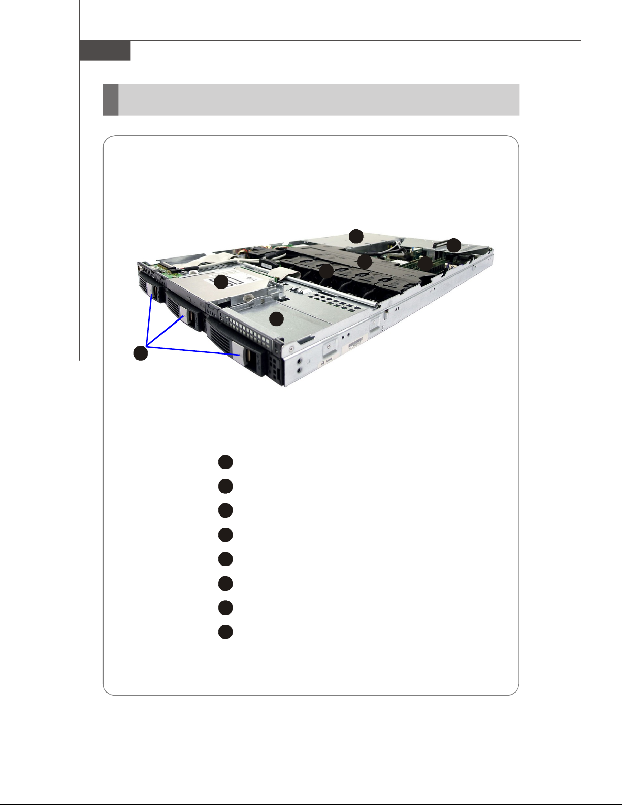
System Overview
Top View
1-2
1
HDD Tray
Slim CD-ROM Drive
Tape Module Tray
Axial Fan Module (redundant)
Fan Duct
Memory DIMM Slots
PCI Riser Card Bracket
SSI EPS 1U Power Supply
Page 13
2
3
4
5
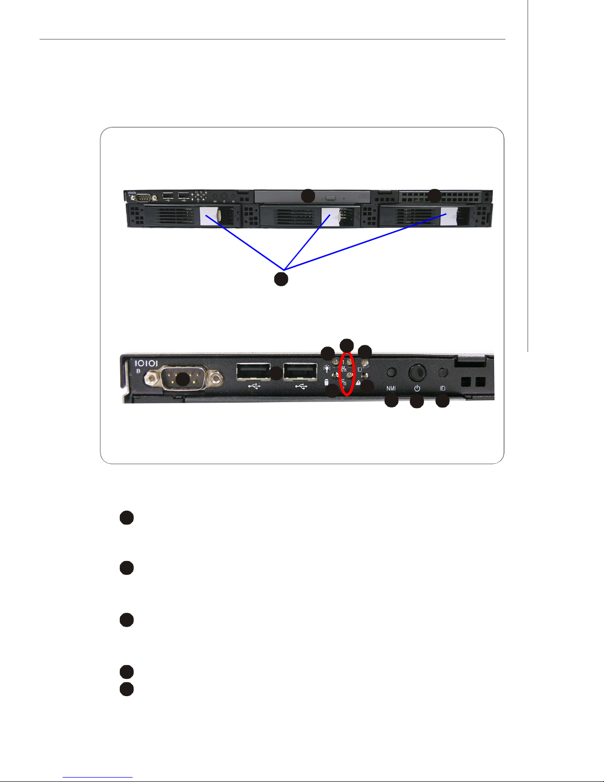
Front View
46759108
2
3
Front Bezel
Getting Started
1
CD-ROM Drive
1
Slim CD-ROM Drive
Tape Module Tray
Tape Module Tray
HDD Bay
Swappable Hard Disk Drive Bays
Port
Serial Port
11
12
13
USB Ports
1-3
Page 14

MS-9272 Server
6
7
8
9
LED
Power LED
This indicator shows the power status of the system. It glows when the main
power is turned on.
HDD Activity LED
This indicator shows the activity status of the hard disk drive. It flashes
when the system is accessing data on the hard disk and remains off when
no disk activity is detected.
Status LEDs of LAN# 1/2
1. The green LED is on when there is an active connection on the LAN port.
2. This LED flashes when transmitting or receiving activities to or from the
system are detected.
System ID LED
10
System Status LED
Button
11
NMI (Non-Maskable Interrupt) Switch
12
Power Button
Press this button once to shut down the system, and then once to switch on.
13
System ID Button
1-4
Page 15
Getting Started
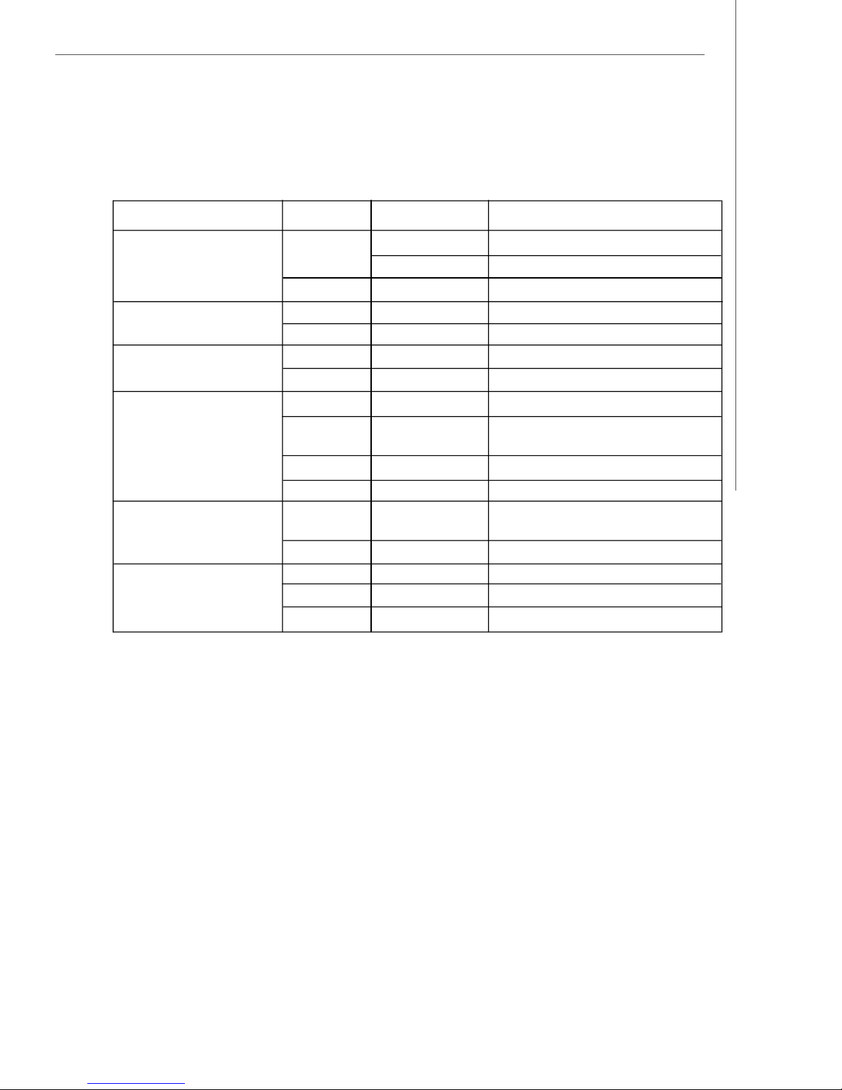
v Front Bezel LEDs
LED Color State Description
Power/Sleep Green On Legacy power on/ACPI S0 state
Blink (~1/sec)Sleep/ACPI S1 state
Off Off Power off/ACPI S4, S5 state
HDD Activity Green Blink HDD access activity
Off Off No disk activity
LAN1/LAN2 Activity Green On LAN link
Green Blink LAN access activity
System Status Green On Running/normal operation
Amber On Critical or non-recoverable
condition
Amber Blink Non-critical condition
Off Off POST/system stop
System ID Blue On Identify active via command
or button
Off Off No identification
Swappable HDD Green Blink HDD access
Status w/ SAF-TE Amber On Failure or rebuild stopped
Amber Blink (~1/sec)Rebuild
1-5
Page 16
MS-9272 Server
2
3
4
5
6
7
8
9
2345678
9
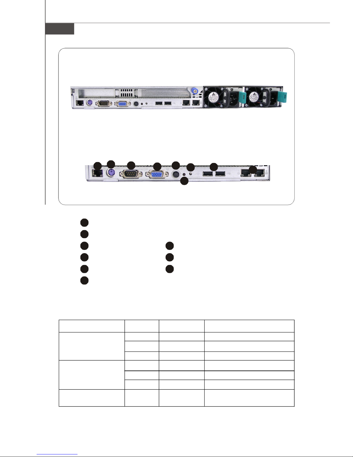
Rear View
Rear Bezel
1
1
10/100Mbps LAN Jack
PS/2 Keyboard/Mouse Connector (through Y-type converter)
Serial Port
System ID Button
System ID LED
VGA Port
NMI Switch
USB Ports
Gigabit LAN Jackss
v Rear Bezel LEDs
LED Color State Description
RJ45 NIC 1 Linkage Green On LAN linked
/RJ45 NIC 2 Linkage Green Blinking LAN accessing
/RJ45 NIC 3 Linkage Off Off No LAN linked
RJ45 NIC 1 Access Yellow On Gigabit mode access
/RJ45 NIC 2 Access Green On 100M mode access
/RJ45 NIC 3 Access Off Off 10M mode access
System ID Blue On/ Identified as active via
Blinking command or button
1-6
Page 17
Getting Started
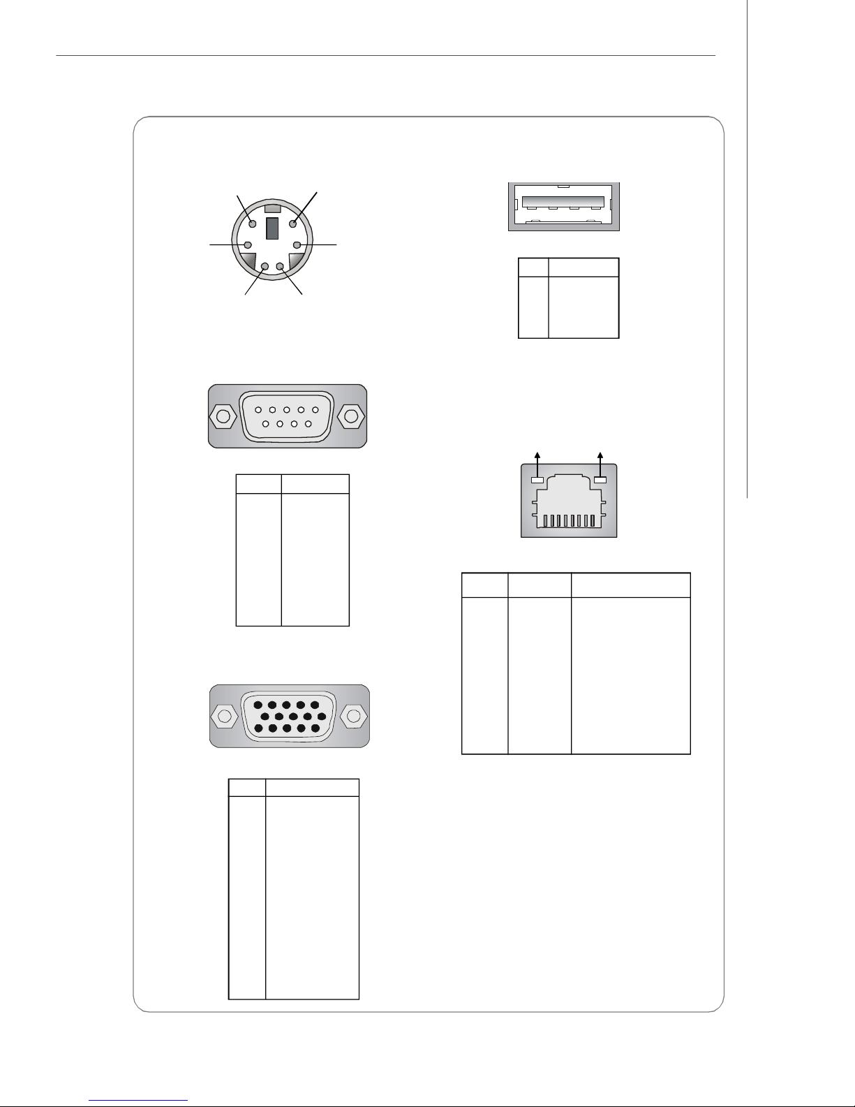
Mouse/Keyboard Connector
Pin6
Mouse Clock
Pin2
Mouse Data
Pin5
Keyboard Clock
Pin3 GNDPin4 VCC
Pin1
Keyboard Data
Serial Port
1 2 3 4 5
6 7 8 9
PIN SIGNAL
1 DCD
2 SIN
3 SOUT
4 DTR
5 GND
6 DSR
7 RTS
8 CTS
9 RI
VGA Port
5
15
1
11
USB Port
1 2 3 4
PIN SIGNAL
1 VCC
2 -Data
3 +Data
4 GND
Gigabit LAN Jack
Activity Indicator
PIN SIGNAL DESCRIPTION
1 D0P Differential Pair 0+
2 D0N Differential Pair 03 D1P Differential Pair 1+
4 D2P Differential Pair 2+
5 D2N Differential Pair 26 D1N Differential Pair 17 D3P Differential Pair 3+
8 D3N Differential Pair 3-
Link Indicator
8 1
PIN SIGNAL
1 RED
2 GREEN
3 BLUE
4 N/C
5 GND
6 GND
7 GND
8 GND
9 +5V
10 GND
11 N/C
12 SDA
13 Horizontal Sync
14 Vertical Sync
15 SCL
1-7
Page 18
MS-9272 Server
System Specifications
Processor Support
- 1-2 Xeon processor(s)
- Dempsey/Woodcrest, LGA771 socket
- Supports Intel EM64T, DEP (XD bit)
Supported FSB
- FSB 667/1066/1333MHz
Chipset
- North Bridge: Intel® 5000P
- South Bridge: Intel® ESB2
- Super IO/ Server Management Bridge: ServerEnginesTM Pilot
Memory Support
- 12 DDRII 533/667 FB-DIMM (Fully Buffered Dual-In-line DIMM) slots
- Maximum 48 GB
LAN
- Supports Gigabit Ethernet by Intel 82563EB
SAS (Optional)
- SAS Host Controller: LSI Logic SAS1068
- A data transfer rate of up to 3Gb/s
SATA (Optional)
- 4 SATAII ports support 4 SATAII devices
- Storage and data transfers at up to 300 MB/s
Connectors
Front I/O Port
- USB 2.0 ports *2
- Serial (COMB) *1
- Power/Sleep, NMI, Reset button
- Power/Sleep, HDD LED, LAN1 LED/ LAN2 LED
- Unit ID button*1 (UID; System ID)
- Hot-Swap SAS HDD tray
Rear I/O Port
- USB 2.0 ports *2
- Serial(COMA) *1 + Serial (XOR 1*front)
- VGA *1
- LAN *3
1-8
Page 19
Getting Started
Slots
- PCIX64 (100MHz) *1 (Full Height)
- PCI-E by 8 *1 (Low Profile)
- PCI-E by 8 *1 (Optional Long Card Support)
Certification
- Safety: UL, cUL, CCC
- EMI: CE/FCC Class A, BSMI
Chassis
- Form Factor: 1U-28”
- Externally Swappable 3.5 inch SAS HDD Bay x 3 (standard)
or 3.5 inch SATAII HDD Bay x 3 (optional)
- Slim CD Drive Bay x 1
- Full height slot x 1
- Low profile slot x 1
- Chassis Dimension: 467mm (W) X 43mm (H) X 728.60mm (D)
Power Supply
- 650 Watt Redundant_PSU
l PFC Function: Yes
l Form Factor: SSI EPS 1U
l Redundancy Support: 1 + 1 Redundant
l Safety Mark: UL, cUL, CE-mark, CCC and BSMI
- 650 W None-Redundant_PSU (Option)
l PFC Function: Yes
l Form Factor: SSI EPS 1U
l Safety Mark: UL, cUL, CE-mark, CCC and BSMI
For more information on compatible components, please visit
http://www.msi.com.tw/program/products/server/svr/pro_svr_qvl.php
1-9
Page 20
MS-9272 Server
B
A
T
T
+
B
A
T
T
+
(Optional)
(Optional)
J_FORCE_MODE
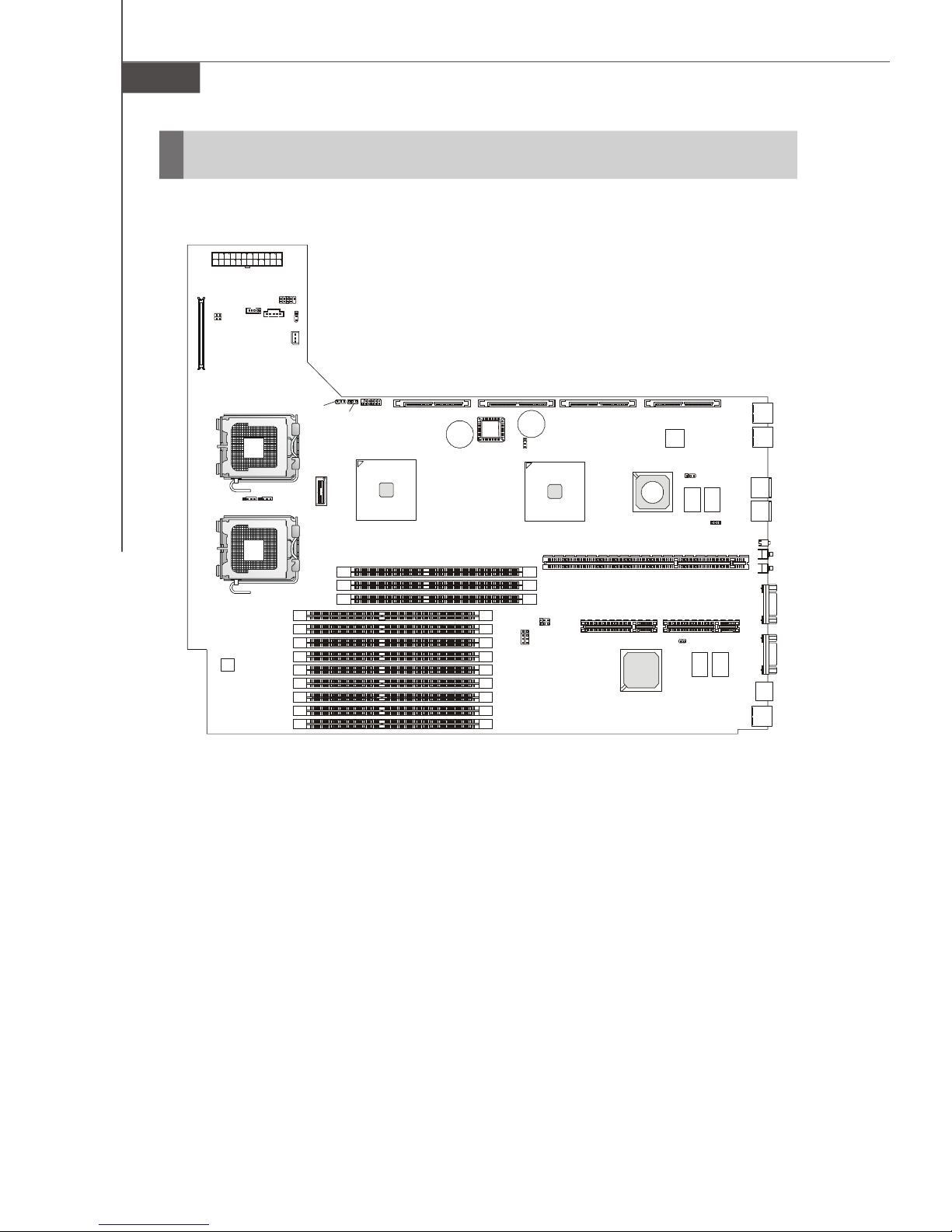
Mainboard Layout
JPWR1
JUSB3001
JUSB3002
JRST3000
U3000
JPBT3000
J3003
J_FANSEL
J_IPMB
CPU2CPU1
J4 J5
DIMM11
DIMM12
DIMM13
DIMM21
DIMM22
DIMM23
DIMM31
DIMM32
DIMM33
J_PASSWORD
DIMM41
DIMM42
DIMM43
J_RECOVERY
J3002
Intel
5000P
SATA2
(Optional)
BIOS
SATA1
(Optional)
J12
JBAT1
J_FRB3
J11
MS-9172 v1.X Server Board
SAS2
Intel
ESB2
PCIE1 PCIE2
SAS1068
PCI1
ServerEngines
SAS1
Intel
82563EB
JSASRAID2
LSI
J10
JSASRAID1
LAN2
LAN1
USB3004
USB3003
D3003
JNMI1
JID3000
KBMS1
LAN3
VGA1
COM1
1-10
Page 21
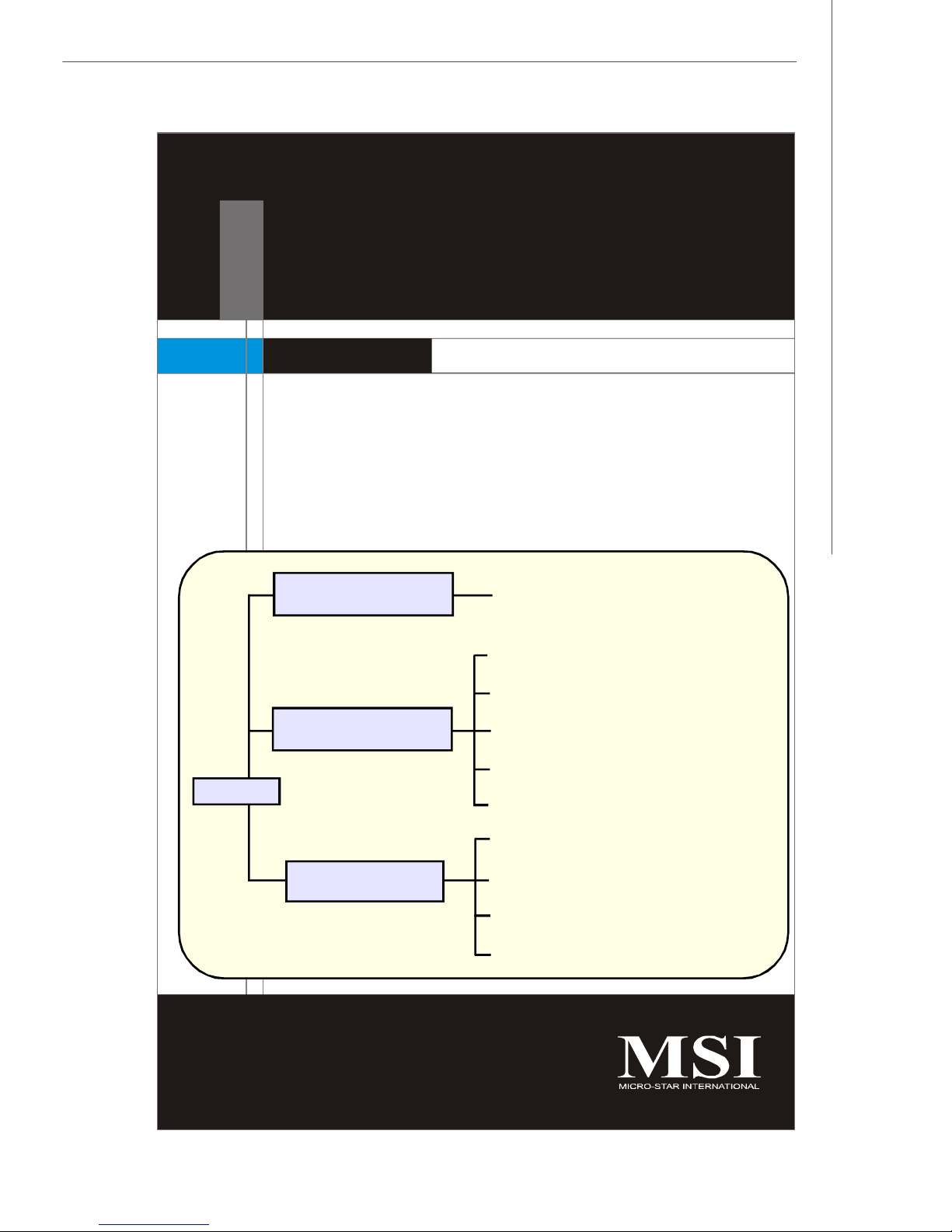
Hardware Setup
Chapter 2
Hardware Setup
Refer to the system assembly flowchart and the chart
below to determine the proper sequence of removing
or installing components to the server.
MS-9272
Mainboard Hardware
System Assembly
Rack Mounting
CPU, Memory, Power Supply, Back
Panel, Connectors, Jumpers, Slot
Chassis Cover
CPU, Heatsink
Memory
Riser Card
Hard Disk Drives
Chassis Ears and Rails
Rack Rails
Chassis into the Rack
Chassis off the Rack
2-1
Page 22

MS-9272 Server
Quick Components Guide
JPWR1, p.2-7
JRST3000,
JPBT3000, p.2-11
JUSB3001,
JUSB3002, p.2-10
JSASRAID2/
JSASRAID1, p.2-14
SATA2/SATA1, p.2-9
J3003,
p.2-11
CPU1/2,
p.2-3
J_FANSEL, p.2-14
J_IPMB, p.2-11
J_PASSWORD, p.2-13
J_RECOVERY, p.2-13
SAS2/SAS1, p.2-8
Back Panel
I/O, p.1-6
BIOS
JBAT1, p.2-12
J10, p.2-13
PCI-Class Slots, p.2-15
DDRII DIMM Slots, p.2-4
2-2
Page 23
Hardware Setup
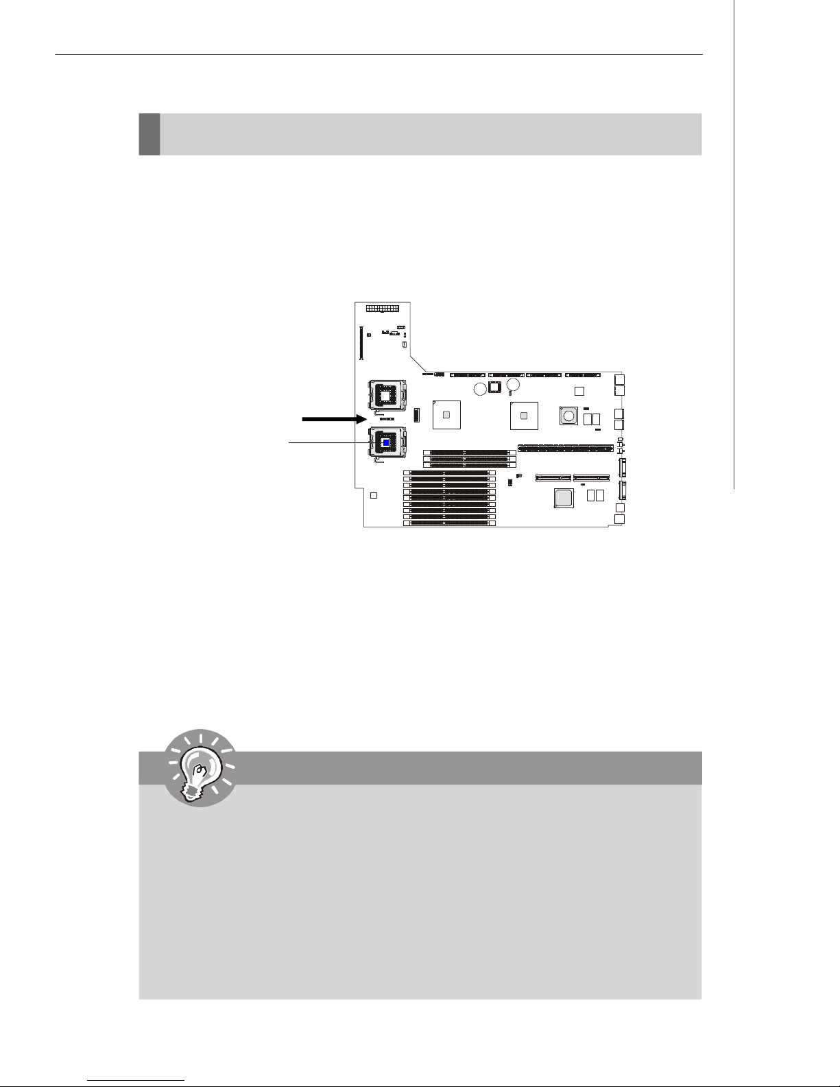
CPU (Central Processing Unit)
The mainboard supports Single/Dual Intel® Xeon™ (Dempsey, Woodcrest) processor
(s) in the LGA 771 package. You can install SINGLE or DUAL CPUs on the board to
meet your own needs. Keep the following points in mind before installing CPU(s):
1. If SINGLE CPU is intended, always install the CPU on the CPU1 socket and
install a dummy heatsink on the CPU2 socket, which will direct inlet air to
the CPU1 socket for better heat dissipation.
BIOS
recommended inlet air
direction
CPU1
2. To install DUAL CPUs on the board, you must use the same type of CPUs
running at the same FSB frequency.
When you are installing the CPU, make sure the CPU has a heatsink and a
cooling fan attached on the top to prevent overheating. If you do not find the
heatsink and cooling fan, contact your dealer to purchase and install them before
turning on the computer.
For more information on compatible components, please visit http://www.msi.com.
tw/program/products/server/svr/pro_svr_qvl.php .
Important
1. Overheating will seriously damage the CPU and system. Always make
sure the cooling fan can work properly to protect the CPU from overheating.
2. The system temperature needs to remain under 45°C. We highly recommend that the direction of inlet air should follow the direction indicated
above for better cooling effect.
3. Make sure that you apply an even layer of heat sink paste (or thermal tape)
between the CPU and the heatsink to enhance heat dissipation.
4. While replacing the CPU, always turn off the power supply or unplug the
power supply’s power cord from the grounded outlet first to ensure the
safety of CPU.
2-3
Page 24
MS-9272 Server
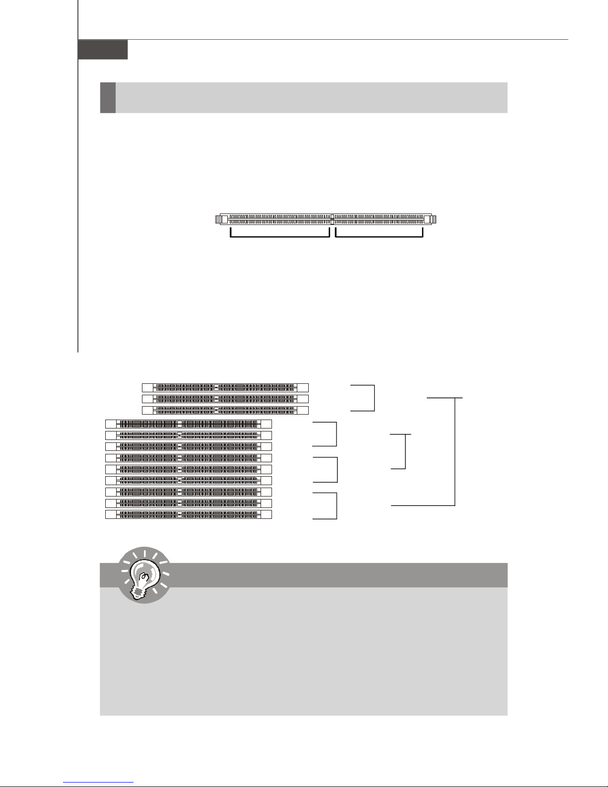
Memory
The mainboard supports up to twelve 240-pin 533/667MHz ECC DDRII FB-DIMM slots
to provide the maximum of 48GB memory capacity.
For more information on compatible components, please visit http://www.msi.com.
tw/program/products/server/svr/pro_svr_qvl.php.
DDRII
240-pin, 1.8V
64x2=128 pin 56x2=112 pin
Memory Population Rules
This mainboard supports DDRII 533/667 FBD memory interface.
Each DIMM slot supports up to a maximum size of 4 GB. Users can install either single-
or double-sided modules depending on their needs.
DIMM41
DIMM11
DIMM12
DIMM13
DIMM21
DIMM22
DIMM23
DIMM31
DIMM32
DIMM33
DIMM42
DIMM43
Channel 4
Channel 1
Channel 2
Channel 3
Dual
Channel
Dual
Channel
Important
1. To enable successful system boot-up, always insert the memory modules
into the DIMM11 first (Channel1/ 1st).
2. In dual-channel mode, Channel 1 works in pair with Channel 2 while Channel
3 works in pair with Channel 4. In other words, Channel 2 cannot work
independently with Channel 1 unplugged and Channel 4 cannot work alone
with Channel 3 unplugged. Channel 3 & 4 cannot work when Channel 1 & 2
are unplugged.
3. In dual-channel mode, DIMM modules must be of the same type and density.
2-4
Page 25
Hardware Setup
Check the numbers of your DIMM modules and follow the population rules to install the
memory.
Numbers of DIMM Population Rules
1 DIMM Module DIMM 11
2 DIMM Modules <a> DIMM 11, DIMM 12
OR
<b> DIMM 11, DIMM 21
3 DIMM Modules DIMM 11, DIMM 12, DIMM 13
4 DIMM Modules <a> DIMM 11, DIMM 21, DIMM 31, DIMM 41
OR
<b> DIMM 11, DIMM 12, DIMM 21, DIMM22
6 DIMM Modules <a> DIMM 11, DIMM 21, DIMM 31, DIMM 41, DIMM 12, DIMM 22
OR
<b> DIMM 11, DIMM 21, DIMM 31, DIMM 41, DIMM 32, DIMM 42
OR
<c> DIMM 11, DIMM 12, DIMM 13, DIMM 21, DIMM 22, DIMM 23
8 DIMM Modules <a> DIMM 11, DIMM 21, DIMM 31, DIMM 41, DIMM 12, DIMM 22,
DIMM 32, DIMM 42
OR
<b> DIMM 11, DIMM 21, DIMM 31, DIMM 41, DIMM 32, DIMM 33,
DIMM 42, DIMM 43
OR
<c> DIMM 11, DIMM 12, DIMM 13, DIMM 21, DIMM 22, DIMM 23,
DIMM 31, DIMM 41
10 DIMM Modules <a> DIMM 11, DIMM 12, DIMM 13, DIMM 21, DIMM 22, DIMM 23,
DIMM 31, DIMM 32, DIMM 41, DIMM 42
OR
<b> DIMM 11, DIMM 12, DIMM 21, DIMM 22, DIMM 31, DIMM 32,
DIMM 33, DIMM 41, DIMM 42, DIMM 43
12 DIMM Modules DIMM 11, DIMM 12, DIMM 13, DIMM 21, DIMM 22, DIMM 23,
DIMM 31, DIMM 32, DIMM 33, DIMM 41, DIMM 42, DIMM 43
2-5
Page 26

MS-9272 Server
Installing DDRII Modules
1. The memory module has only one notch on the center and will only fit in the right
orientation.
2. Insert the memory module vertically into the DIMM slot. Then push it in until the
golden finger on the memory module is deeply inserted in the DIMM slot.
Important
You can barely see the golden finger if the memory module is properly inserted
in the DIMM slot.
3. The plastic clip at each side of the DIMM slot will automatically close.
Volt
Notch
Important
Make sure that you install memory modules of the same type and density on
DDRII DIMM slots.
2-6
Page 27
Hardware Setup
Power Supply
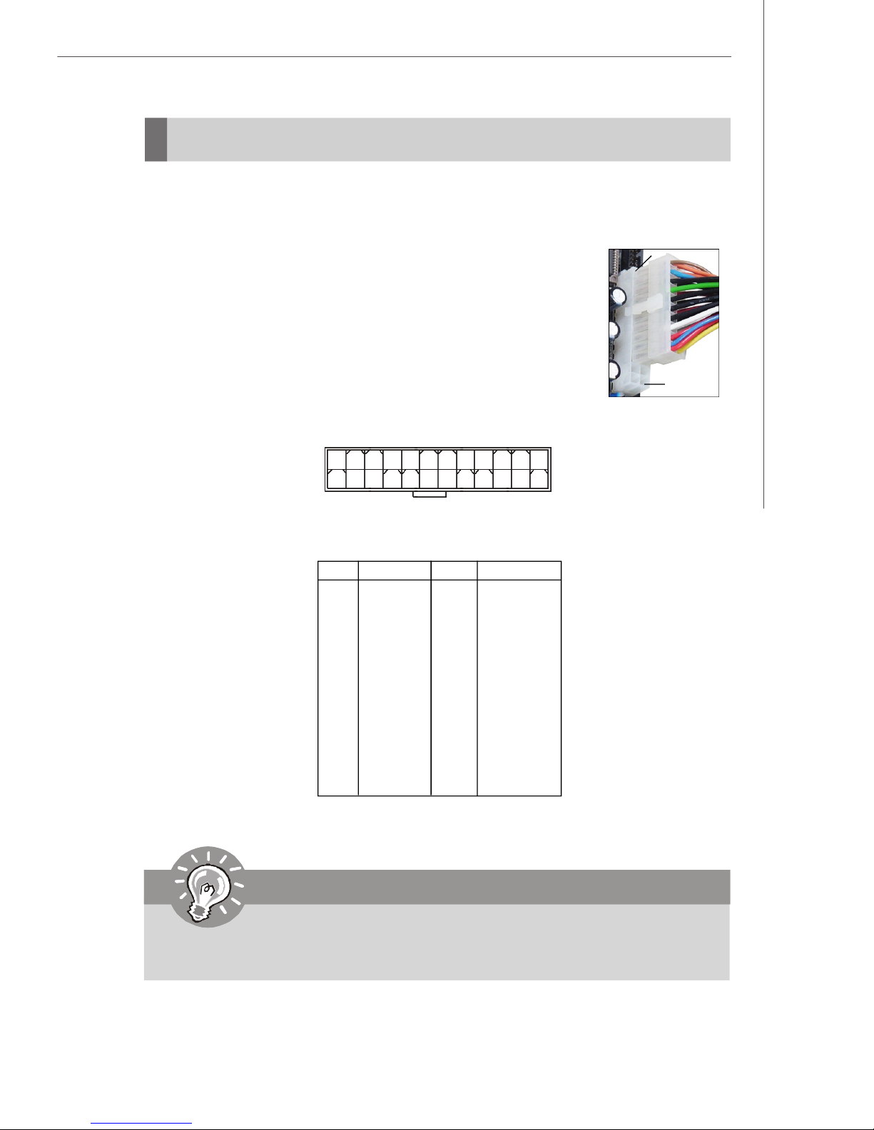
SSI 24-Pin System Power Connector: JPWR1
This connector allows you to connect an SSI power supply. To connect the SSI
power supply, make sure the plug of the power supply is inserted
in the proper orientation and the pins are aligned. Then push
down the power supply firmly into the connector.
You may use the 20-pin ATX power supply or 24-pin SSI power
supply as you like. If you’d like to use the ATX power supply,
please plug your power supply along with pin 1 & pin 13 (refer to
the image at the right hand). There is also a foolproof design on
pin 11, 12, 23 & 24 to avoid wrong installation.
JPWR1
pin 13
pin 12
1
13
JPWR1 Pin Definition
PIN SIGNAL
1 +3.3V
2 +3.3V
3 GND
4 +5V
5 GND
6 +5V
7 GND
8 PWR OK
9 5VSB
10 +12V
11 +12V
12 NC
12
24
PIN SIGNAL
13 +3.3V
14 -12V
15 GND
16 PS-ON#
17 GND
18 GND
19 GND
20 Res
21 +5V
22 +5V
23 +5V
24 GND
Important
Power supply of 350watts (and above) is highly recommended for system
stability.
2-7
Page 28
MS-9272 Server
Connectors
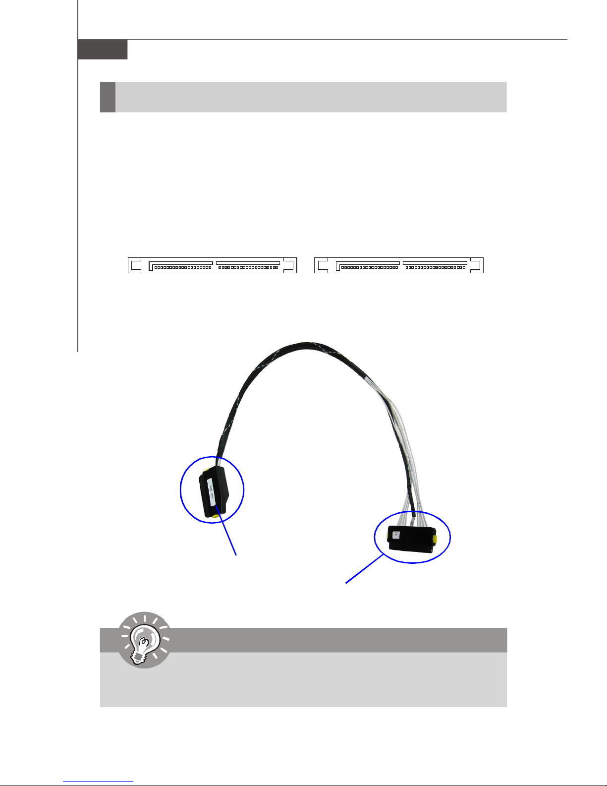
Serial Attached SCSI Connectors: SAS1, SAS2 (Optional)
The SAS connector is a new generation serial communication protocol for devices
designed to allow for much higher speed data transfers. It supports data transfer
speeds up to 3 Gbit/s. SAS uses serial communication instead of the parallel method
found in traditional SCSI devices but still uses SCSI commands for interacting with
SAS devices. Each SAS connector can connect to 4 disk drives.
SAS2 SAS1
SAS Cable (Optional)
Connect to the SAS connector on the back plate
Important
Please do not fold the SAS cable into 90-degree angle. Otherwise, data loss
may occur during transmission.
2-8
Connect to the onboard SAS1/SAS2 connector
Page 29
Hardware Setup
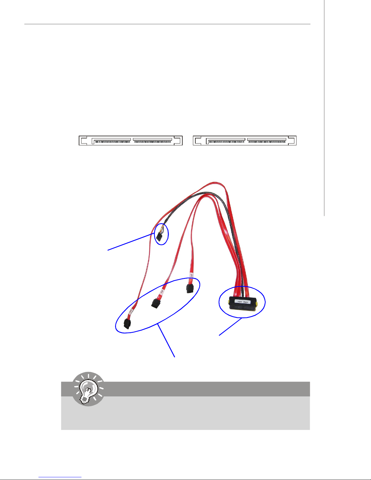
Serial ATA Connectors: SATA1, SATA2 (Optional)
SATA1~SATA2 are high-speed SATAII interface ports and support data rates of
300MB/s. Each SATAII connector can connect to 4 hard disk device.
SATA2 SATA1
SATA Cable (Optional)
Connect to the 5-pin
connector on the back plate
Connect to the onboard SATA1/SATA2 connector
Connect to the SATA connectors on the back plate
Important
Please do not fold the SATA cable into 90-degree angle. Otherwise, data loss
may occur during transmission.
2-9
Page 30

MS-9272 Server
Front USB Connectors: JUSB3001, JUSB3002
The mainboard provides two USB 2.0 pin headers (optional USB 2.0 bracket available)
that are compliant with Intel® I/O Connectivity Design Guide. USB 2.0 technology
increases data transfer rate up to a maximum throughput of 480Mbps, which is 40
times faster than USB 1.1, and is ideal for connecting high-speed USB interface
peripherals such as USB HDD, digital cameras, MP3 players, printers, mo-
dems and the like.
JUSB3001 Pin Definition
PIN SIGNAL PIN SIGNAL
JUSB3001
2
1
10
9
1 USBPWR 2 USBPWR
3 USBP4- 4 USBP55 USBP4+ 6 USBP5+
7 GND 8 GND
9 NC 10 USBOC
JUSB3002 Pin Definition
JUSB3002
1 4
PIN SIGNAL
1 +5V
2 USB3 USB+
4 GND
Important
Note that the pins of VCC and GND must be connected correctly to avoid
possible damage.
2-10
Page 31

Hardware Setup
Reset Button Connector: JRST3000
This connector is designed to connect the system reset button.
JRST3000
Power Switch Connector: JPBT3000
This connector is designed to connect the system power switch.
JPBT3000
IPMB Connector: J_IPMB
This connector is used to connect the IPMB (Intelligent Platform Management Bus)
SMBus.
J_IPMB
3
1
Pin Definition
PIN SIGNAL
1 SMB Data
2 GND
3 SMB Clock
IPMB Power Connector: J3003
This connector is used to connect the power supply of the IPMB (Intelligent Platform
Management Bus) SMBus.
Pin Definition
1
J3003
5
PIN SIGNAL
1 SMB Clock
2 SMB Data
3 PS Alert
4 GND
5 3.3V
2-11
Page 32

MS-9272 Server
Jumpers
Clear CMOS Jumper: JBAT1
There is a CMOS RAM onboard that has a power supply from external battery to keep
the data of system configuration. With the CMOS RAM, the system can automatically
boot OS every time it is turned on. If you want to clear the system configuration, use
the JBAT1 (Clear CMOS Jumper) to clear data.
1
1
3
1
3
JBAT1
Keep Data
Clear Data
Important
You can clear CMOS by shorting 2-3 pin while the system is off. Then return
to 1-2 pin position. Avoid clearing the CMOS while the system is on; it will
damage the mainboard.
2-12
Page 33

Hardware Setup
BIOS Recovery Jumper: J_RECOVERY
Users can short connect pin#2-3 to recover the system BIOS with a Recovery
Floppy. When the system is done with the job, the buzzer will beep to remind the user
to set the jumper to its normal state (pin#1-2 short connected).
J_RECOVERY
1
1 3
Normal
1 3
Recovery
Clear BIOS Password Jumper: J_PASSWORD
The jumper is used to clear the BIOS password. You can clear BIOS password by
shorting 2-3 pin while the system is off. Then return to 1-2 pin position. Avoid clearing
the password while the system is on; it will damage the mainboard.
J_PASSWORD
1
1 3
Normal
1 3
Clear
Write Protection Jumper for ServerEngines Flash ROM: J10
This jumper is used to enable/disable the write protection function for the ServerEngines
Flash ROM. When you intend to access the ServerEngines Flash ROM, uncap this
jumper first. Under normal operation, we suggest that you enable the write protection
function by capping this jumper to protect the ServerEngines Flash ROM from virus
infection.
J10
Enable Write Protection Disable Write Protection
2-13
Page 34

MS-9272 Server
Fan Selection Jumper: J_FANSEL
This jumper determines whether all fans or only specified fans will work.
1
1
3
1
3
J_FANSEL
Specified Fans
All Fans
SAS RAID Jumper: JSASRAID1, JSASRAID2
These jumpers specify the SAS HDD mode and have to be simultaneously configured
as “SAS RAID” or “Non SAS RAID”.
Non SAS RAID
JSASRAID1 JSASRAID2
1 3
13
SAS RAID
2-14
JSASRAID1 JSASRAID2
3
1 1
3
Page 35

Hardware Setup
Slots
PCI (Peripheral Component Interconnect) Slot
The PCI-class slots support LAN cards, SCSI cards, USB cards, VGA cards, and
other add-on cards that comply with PCI specifications.
PCI Express architecture provides a high performance I/O infrastructure for Desktop
Platforms with transfer rates starting at 2.5 Giga transfers per second over a PCI
Express x1 lane for Gigabit Ethernet, TV Tuners, 1394 controllers, and general purpose I/O. Also, desktop platforms with PCI Express Architecture will be designed to
deliver highest performance in video, graphics, multimedia and other sophisticated
applications. Moreover, PCI Express architecture provides a high performance graphics
infrastructure for Desktop Platforms doubling the capability of existing AGP 8x designs with transfer rates of 4.0 GB/s over a PCI Express x16 lane for graphics
controllers, while PCI Express x1 supports transfer rate of 250 MB/s.
PCI Express x8 Slot
64-bit PCI-X Slot + PCI Express x8 Slot
PCI Interrupt Request Routing
The IRQ, acronym of interrupt request line and pronounced I-R-Q, are hardware lines
over which devices can send interrupt signals to the microprocessor. The PCI IRQ
pins are typically connected to the PCI bus pins as follows:
DEVICE IDSEL INT A INT B INT C INT D REQ GNT
LSI 1068 AD26 PXIRQ_N4 NA NA NA PXREQ_N1 PXGNT_N1
PCI1-ZCR AD24 PXIRQ_N0 PXIRQ_N1 ZCR_INT PXIRQ_N3 PXREQ_N2 PXGNT_N2
PCI1-Normal AD25 PXIRQ_N1 PXIRQ_N2 PXIRQ_N3 PXIRQ_N0 PXREQ_N3 PXGNT_N3
Important
When adding or removing expansion cards, make sure that you unplug the
power supply first. Meanwhile, read the documentation for the expansion card
to configure any necessary hardware or software settings for the expansion
card, such as jumpers, switches or BIOS configuration.
2-15
Page 36

MS-9272 Server
START
System Assembly Flowchart
The following flowchart shows basic system assembly procedures. Please note
that always wear anti-static gloves when handling electrical components and exercise caution during the installation process. For more information, contact your local
dealer or experienced technician.
REMOVE CHASSIS COVER
INSTALL
CPU & HEATSINK
INSTALL
MEMORY MODULES
REMOVE
RISER CARD BRACKET
2-16
INSTALL
RISER CARDS
Page 37

REPLACE
RISER CARD BRACKET
INSTALL
HARD DISK DRIVES
Hardware Setup
CONNECT HDD
& POWER CORDS
CHECK IF ALL PARTS
ARE PROPERLY CONNECTED
REPLACE
CHASSIS COVER
FINISH
2-17
Page 38

MS-9272 Server
System Assembly
Removing the Chassis Cover
1. Loosen the thumbscrew on the rear bezel of the system.
2. Press the release buttons and slide the rear chassis cover backwards to remove
it from the chassis.
3. Press the release buttons and slide the front chassis cover forwards to remove
it from the chassis.
2-18
Page 39

Replacing the Chassis Cover
1. Replace the front chassis
cover and slide it backwards.
2. Replace the rear chassis cover
and slide it forwards.
Hardware Setup
3. Fasten the thumbscrew on the rear bezel of the system.
Important
Before you remove or install any components, make sure the server is not
turned on or connected to the AC power.
2-19
Page 40

MS-9272 Server
CPU, Heatsink, and Fan Duct
1. On top of the CPU is a fan duct designed to enhance heat dissipation
of the CPU. Lift up & remove the fan
duct before installing the CPU.
2. Locate the first CPU socket. (The CPU has a plastic cap on it to protect the contact
from damage. Before installing the CPU, always cover it to protect the socket
pins.)
3. Remove the plastic cap from the load plate. The pins of the socket reveal.
CPU1
4. Raise the load lever up to its full extent.5. Open the load plate.
CPU2
2-20
Page 41

Hardware Setup
6. After confirming the CPU direction (indicated below with red circles) for correct
mating, put down the CPU in the socket housing frame. Be sure to grasp on the
edge of the CPU base. Note that the alignment keys are matched.
7. Visually inspect if the CPU is seated well into the socket. If not, take out the CPU
with pure vertical motion and reinstall.
Alignment Key
Yellow triangle is the Pin 1 indicator
8. Cover the load plate onto the package.
9. Press down the load lever lightly onto the load plate and then secure the lever
with the hook under the retention tab.
10.Follow the same procedures to install the second CPU.
Note: To install DUAL CPUs
on the board, you must use
the same types of CPUs
running at the same FSB
frequency.
2-21
Page 42

MS-9272 Server
11.Place the heat sink on top of CPU1 and secure the screws on both sides.
Note: The heatsink has to be installed to prevent the CPU from overheating.
12.Follow the same procedures to install the second heatsink.
13.Replace the fan duct on top of the
heatsinks.
Note: To ensure proper cooling,
make sure the heatsinks & the
fan duct are properly installed.
2-22
Page 43

DDRII Memory
1. Locate the DIMM slots on the
mainboard. Insert the memory module vertically into the DIMM slot. Then
push it in until the golden finger on
the memory module is deeply inserted
in the socket. The plastic clip at each
side of the DIMM slot will automatically close.
2. For optimal system performance, at
least two memory modules must be
installed.
Hardware Setup
BIOS
Important
DIMM11
DIMM12
DIMM13
DIMM21
DIMM22
DIMM23
DIMM31
DIMM32
DIMM33
DIMM41
DIMM42
DIMM43
Channel 4
Channel 1
Channel 2
Channel 3
To enable successful system boot-up, always insert the memory modules into
the DIMM11 first (Channel1/ 1st).
2-23
Page 44

MS-9272 Server
PCI Expansion Card
1. Locate the riser card bracket and lift it up from the chassis.
2. Unscrew the cover plates and put them aside for later use.
3. Insert the expansion card into an appropriate PCI-class slot on the riser card.
2-24
Page 45

Hardware Setup
4. Screw to secure the expansion card bracket.
5. Place the riser card bracket on top of the PCI slots on the motherboard. Align the
riser card golden fingers with the PCI slots. Then align the rear part of the bracket
with the U-shaped cuts on the chassis.
6. Push the riser card bracket carefully down with even force on both sides.
2-25
Page 46

MS-9272 Server
Hard Disk Drive
1. To release the hot-swapping HDD holder, flip open its lever and pull the holder out
of the bay.
2. Unscrew both sides of the HDD holder to release the tray.
3. Take the tray out and put it aside.
2-26
Page 47

Hardware Setup
4. At the sides of the HDD are four screw holes, two on each side. Users will find
on the HDD holder four identical screw holes as on the HDD. Place the HDD into
the holder and align the screw holes on the HDD with the ones on the holder.
Secure the HDD with four screws supplied by the HDD vendor.
5. Insert the HDD set into the bay and press the lever back in place.
2-27
Page 48

MS-9272 Server
Rack Mounting
Chassis Ears
1. Insert the chassis ear into the chassis (as marked below).
2. Push it in until it fits firmly. Screw to secure the chassis ear.
3. Follow the same procedures to install the second chassis ear.
2-28
Page 49

Hardware Setup
Chassis Rails
1. The chassis rails and rack rails have
been assembled together beforehand.
The first thing to do with the rail set is to
take the chassis rails off the rack rails.
Note:
1. Only the service personnel
can slide out the rack rails.
2. The chassis rail engraved with
“RIGHT SLIDE” on the inner side
should be screwed to the right
side of the chassis whereas the
“LEFT SLIDE” should be screwed
to the left side.
2. Pull the chassis rail gently out until the locking tab locks the rail.
3. Simultaneously press down the locking tab and pull out the chassis rail. The
chassis rail should slide easily off the rack rail.
4. Follow the same procedures to disassemble the second chassis rail.
Note: The chassis rail is designed with a locking tab which can (1) hold the
system firmly to the rack, and (2) lock the system halfway without sliding out
of the rack rails.
2-29
Page 50

MS-9272 Server
5. On each side of the chassis are three hooks to lock the chassis rail. First align the
chassis hooks with the holes on the rail. Secure the rail to the chassis and push
the rail backwards until it gets locked by the chassis hooks.
Push the rail backwards until it
gets locked by the chassis hooks.
Note: The chassis rail engraved
with “RIGHT SLIDE” on the inner
side should be screwed to the
right side of the chassis whereas
the “ LEFT SLIDE” should be
screwed to the left side.
6. Screw the chassis rail to the chassis. Each chassis rail has two screw holes.
Follow the same procedures to install the second chassis rail.
2-30
Page 51

Rack Rails
1. Locate the triangle mark on the rack
and install 3 screw holders to the
rack as shown.
2. Align the rack rail with the rack and
screw the rail to the rack by securing one screw to the bottom screw
holder.
Hardware Setup
3. Follow the same procedures to secure the rail on the rear and to install
the second rack rail.
Secure one screw to the
bottom screw holder.
2-31
Page 52

MS-9272 Server
Chassis into the Rack
1. To slide the system into the rack, first align the chassis rails with the rack rails
and push the system backwards until the locking tab clicks.
2. Simultaneously press down the locking tabs on both sides of the chassis rails
and push the system backwards. The system should slide easily into the rack.
Note: The chassis rail is designed with a locking tab which can (1) hold the
system firmly to the rack, and (2) lock the system halfway without sliding out
of the rack rails.
Press down the locking tabs
on both sides.
3. Screw the system firmly to the rack.
2-32
Page 53

Chassis off the Rack
1. To slide the system off the rack, first
seize the system by its ears and
gently pull the system out.
2. The system will be locked halfway
while being pulled out. Simultaneously press down the locking tabs
on both sides of the chassis and pull
the system forwards. The system
should slide easily off the rack.
Hardware Setup
Press down the locking tabs
on both sides.
Note: The chassis rail is designed with a locking tab which can (1) hold the
system firmly to the rack, and (2) lock the system halfway without sliding out
of the rack rails.
2-33
Page 54

Chapter 3
BIOS Setup
This chapter provides information on the BIOS Setup
program and allows you to configure the system for
optimum use.
You may need to run the Setup program when:
BIOS Setup
² An error message appears on the screen during the
system booting up, and requests you to run SETUP.
² You want to change the default settings for cus-
tomized features.
3-1
Page 55

MS-9272 Server
Entering Setup
Power on the computer and the system will start POST (Power On Self Test) process.
When the message below appears on the screen, press <F2> key to enter Setup.
Press F2 to enter SETUP
If the message disappears before you respond and you still wish to enter Setup,
restart the system by turning it OFF and On or pressing the RESET button. You may
also restart the system by simultaneously pressing <Ctrl>, <Alt>, and <Delete> keys.
Important
1.The items under each BIOS category described in this chapter are under
continuous update for better system performance. Therefore, the description may be slightly different from the latest BIOS and should be held for
reference only.
2.Upon boot-up, the 1st line appearing after the memory count is the BIOS
version. It is usually in the format:
P9172IMS V1.0 051506 where:
1st digit refers to BIOS maker as A = AMI, W = AWARD, and P =
PHOENIX.
2nd - 5th digit refers to the model number.
6th digit refers to the chipset as I = Intel, N = nVidia, and V = VIA.
7th - 8th digit refers to the customer as MS = all standard customers.
V1.0 refers to the BIOS version.
051506 refers to the date this BIOS was released.
3-2
Page 56

Control Keys
BIOS Setup
Key
<F1> or <Alt-H>
<Esc>
↔ arrow keys
↑ or ↓ arrow keys
<Home> or <End>
<PgUp> or <PgDn>
<F5> or <->
<F6> or <+>or <Space>
<F9>
<F10>
<Enter>
Function
General Help window
Exit this menu
Select a different menu
Move cursor up and down
Move cursor to top or bottom of window
Move cursor to next or previous page
Select the previous value for the field
Select the next value for the field
Load the default configuration values for this menu
Save and exit
Execute command or enter submenu
Getting Help
After entering the Setup menu, the first menu you will see is the Main Menu.
Main Menu
The main menu lists the setup functions you can make changes to. You can use the
arrow keys ( ↑↓ ) to select the item. The on-line description of the highlighted setup
function is displayed at the bottom of the screen.
Sub-Menu
If you find a right pointer symbol (as shown in the right view) appears to the left of
certain fields that means a sub-menu can be
launched from this field. A sub-menu contains
additional options for a field parameter. You can
use arrow keys ( ↑↓ ) to highlight the field and
press <Enter> to call up the sub-menu. Then you
can use the control keys to enter values and move from field to field within a submenu. If you want to return to the main menu, just press the <Esc >.
General Help <F1>
The BIOS setup program provides a General Help screen. You can call up this screen
from any menu by simply pressing <F1>. The Help screen lists the appropriate keys
to use and the possible selections for the highlighted item. Press <Esc> to exit the
Help screen.
3-3
Page 57

MS-9272 Server
The Menu Bar
Once you enter PhoenixBIOS Setup Utility, the Main Menu will appear on the
screen. On the Main Menu screen, you will see basic BIOS settings including system
time & date, and the setup categories the BIOS supplies. Use Arrow keys to move
among the items and menus, and make changes to the settings.
Main
Use this menu for basic system configurations, such as time, date etc.
Advanced
Use this menu to set up the items of special enhanced features available on your
system’s chipset.
Security
Use this menu to set Supervisor and User Passwords.
Power
Use this menu to specify your settings for power management.
Boot
Use this menu to specify the priority of boot devices.
Exit
This menu allows you to load the BIOS default values or factory default settings into
the BIOS and exit the BIOS setup utility with or without changes.
3-4
Page 58

BIOS Setup
Main
The items inside the Main menu are for basic system information and configuration.
Each item includes none, one or more setup items. Use the Up/Down arrow keys or
<Tab> to highlight the item or field you want to modify and use the <+> or <-> key to
switch to the value you prefer.
System Time
The time format is <HH> <MM> <SS>.
System Date
The date format is <MM> <DD> <YYYY>.
IDE Channel 0 Master/Slave, SATA Port 1/2/3/4
3-5
Page 59

MS-9272 Server
[Type] Press PgUp/<+> or PgDn/<-> to select
[Manual], [None] or [Auto] type. Note that the
specifications of your drive must match with
the drive table. The hard disk will not work
properly if you enter improper information for
this category. If your hard disk drive type is
not matched or listed, you can use [Manual] to
define your own drive type manually.
[Multi-Sector Transfers] Any selection except Disabled determines
the number of sectors transferred per block
[LBA Mode Control] Enabling LBA causes Logical Block Ad-
dressing to be used in place of Cylinders,
Heads and Sectors
[32-Bit I/O] Enables 32-bit communication between
CPU and IDE card
[Tranfer Mode] Selects the method for transferring the data
between the hard disk and system memory
[Ultra DMA Mode] Indicates the type of Ultra DMA
Boot Features
The sub-menu is used to configure system boot-up features.
Boot-time Diagnostic Screen
Select [Enabled] if you want to view the system diagnostic screen during boottime.
QuickBoot Mode
Setting the item to [Enabled] allows the system to boot within 5 seconds since
it will skip some check items.
Extended Memory Testing
This setting determines which type of tests will be performed on extended
memory (above 1M).
System Memory/ Extended Memory
These items show the memory status of the system. (Read-only)
3-6
Page 60

BIOS Setup
Advanced
Items in the menu are divided into several sub-menus. Each sub-menu provides more
settings. To enter the sub-menu, highligh the sub-menu you want to configure and
press <Enter>.
Advanced Chipset Control
The sub-menu is used to configure chipset features for optimal system performance.
3-7
Page 61

MS-9272 Server
ICH USB Control Sub-Menu
This setting controls the listed USB functions by setting the item to the desired
value.
Intel I/O AT Function
This setting enables/disables the Intel I/O Acceleration Function.
SERR Signal Condition
This setting selects ECC error conditions that SERR# is asserted.
Memory Branch Mode
This setting specifies the memory branch mode. Interleaved memory is system
memory divided into two or more sections. Setting to [Interleave] allows memory
to be accessed faster since each section of memory is capable of being utilized
at once.
Branch 0/1 Rank Interleave
This setting selects the number of memory divisions for the Branch 0/1 Rank
Interleave.
Branch 0/1 Rank Sparing
This setting enables Branch 0/1 Rank/DIMM sparing feature.
Enable Multimedia Timer
This setting enables the Multimedia Timer to achieve better resolution for multimedia and other time-sensitive applications.
Parallel ATAA
This setting enables/disables the onboard PATA controller.
Serial ATAA
This setting allows you to enable or disable the onchip Serial-ATA controller.
SATA Controller Mode Option
This setting specifies SATA controller mode. Please note that Pre-Win2K
OS’s do not work in Enhanced mode.
[Compatible] SATA and PATA drives are auto-detected and placed
in Legacy mode.
[Enhanced] SATA and PATA drives are auto-detected and placed
(non-AHCI) in Native IDE mode.
3-8
Page 62

BIOS Setup
Important
Legacy Mode:
*In this mode, system BIOS just assign the traditional 14 and 15
IRQs to use for HDD.
*Older OS’s that do not support switch to Native Mode (DOS, Win2K,
Win98/ME...) should set SATA and PATA to Legacy Mode.
*Maximum 4 ATA devices to connect.
*Combine mode and Non-Combine mode.
-Non-Combined Mode: P-ATA devices only .
Maximum of 4 devices.
-Non-Combined Mode: S-ATA devices only.
Maximum of 2 devices.
-Combined Mode: S-ATA devices
P-ATA devices
Maximum of 2 devices each, total 4
devices at maximum.
Native Mode:
*In this mode, system BIOS will search all available IRQs to use for
HDD.
*New OS’s that support switch to Native Mode (WinXP, Windows .
NET Server) can set SATA and PATA to Native Mode.
*Maximum 6 ATA devices to connect (4 for P-ATA & 2 for S-ATA).
SATA RAID Enable
This feature allows users to enable or disable the RAID function for each
SATA hard disk drive.
3-9
Page 63

MS-9272 Server
Advanced Processor Options
Press <Enter> to view the settings of the onboard CPU(s).
HyperThreading
The processor uses Hyper-Threading technology to increase transaction rates
and reduces end-user response times. The technology treats the two cores
inside the processor as two logical processors that can execute instructions
simultaneously. In this way, the system performance is highly improved. If you
disable the function, the processor will use only one core to execute the
instructions. Please disable this item if your operating system doesn’t
support HT Function, or unreliability and instability may occur.
Important
Enabling the functionality of Hyper-Threading Technology for your computer
system requires ALL of the following platform Components:
* CPU: An Intel® Pentium® 4 / Xeon Processor with HT Technology;
* Chipset: An Intel® Chipset that supports HT Technology;
* BIOS: A BIOS that supports HT Technology and has it enabled;
* OS: An operating system that supports HT Technology.
For more information on Hyper-threading Technology, go to:
www.intel.com/info/hyperthreading
Intel Virtualization Technology
Virtualization enhanced by Intel Virtualization Technology will allow a platform
to run multiple operating systems and applications in independent partitions.
With virtualization, one computer system can function as multiple “virtual” systems.
3-10
Page 64

BIOS Setup
COM Ports Setting
Press <Enter> to enter the sub-menu and the following screen appears:
Serial Port A/B
These settings enable/disable the onboard Serial Port A / B.
Base I/O Address
These settings specify the base I/O port addresses of the onboard Serial
Port A / B.
Interrupt
These settings specify IRQs for the Serial Port A / B.
3-11
Page 65

MS-9272 Server
DMI Event Logging
Press PgUp/<+> or PgDn/<-> to view DMI event logging.
View DMI Event Log
Press [Enter] to view the contents of the DMI event log.
Event Logging
This setting disables/enables the BIOS to log DMI (Desktop Management Interface)
events.
ECC Event Logging
This setting disables/enables the BIOS to log ECC (Error Checking & Correcting)
events.
Clear All DMI Event Logs
When this setting is set to [Yes], the DMI event log will be cleared at next POST
stage. Then, the BIOS will automatically set this option to [No].
Legacy USB Support
Set to [Enabled] if your need to use any USB 1.1/2.0 device in the operating system
that does not support or have any USB 1.1/2.0 driver installed, such as DOS and SCO
Unix.
Option ROM Placement
This setting determines the Option ROM placement. If the system hangs during boot,
please restart the system and enter the BIOS Setup Utility to change this setting.
LSI SAS Controller
This setting enables/disables the onboard LSI SAS controller.
3-12
Page 66

IPMI
Press PgUp/<+> or PgDn/<-> to adjust IPMI configuration.
BIOS Setup
IPMI Specification Version
It shows the support version of IPMI specification. (read only)
BMC Hardware/Firmware Version
It shows the support version of the BMC hardware and firmware. (read only)
System Event Logging
This setting disables/enables the logging of system events.
Existing Event Log Number
It shows the number of existing event logs.
Remaining Event Log Number
It shows the number of remaining event logs.
Event Log Control
Setting to [Enabled] triggers the system event sensors inside BMC (Baseboard
Management Controller).
SYS Firmware Progress
Enabling this selection will log system POST progress.
BIOS POST Errors
Enabling this selection will log BIOS POST errors.
3-13
Page 67

MS-9272 Server
BIOS POST Watchdog
You can enable the system watch-dog timer, a hardware timer that generates
either an NMI or a reset when the software that it monitors does not respond as
expected each time the watch dog polls it (select the time period in a separate
field). Enabling this selection will enable BIOS POST watchdog.
OS Boot Watchdog
You can enable the system watch-dog timer, a hardware timer that generates
either an NMI or a reset when the software that it monitors does not respond as
expected each time the watch dog polls it (select the time period in a separate
field). Enabling this selection will enable OS boot watchdog.
Timer for Loading OS (min)
This setting selects the watchdog time period for loading OS.
Time Out Action
This setting determines the action of the watchdog timer if the OS fails to
boot within the preset time period.
Date Format to Show
This setting determines the displayed date format.
Date Separator
This setting determines which character to use in date entries.
BMC Password
This setting defines the password programmed to BMC.
3-14
Page 68

BIOS Setup
Console Redirection
Press PgUp/<+> or PgDn/<-> to configure Console Redirection. The following submenu
will appear.
Enable UCR over IPMI LAN
This feature enables UCR over the IPMI LAN connection.
Console Type
This setting specifies the type of device to be set as the console.
# of video pages to support
This setting specifies the number of video pages to allocate for Console Redirection when video hardware is not available.
IP Address
This setting defines the IP address of the console.
3-15
Page 69

MS-9272 Server
Security
This section lets you set security passwords to control access to the system at boot
time and/or when entering the BIOS setup program. It also allows you to set virus
protection at hard disk boot sector.
Supervisor Password Is/ User Password Is
It shows the preset supervisor/user password. (read only)
Set Supervisor Password/ Set User Password
Enabling Supervisor Password requires a password for entering Setup. The passwords are not case sensitive. Pressing <Enter> at either Set Supervisor Password
or Set User Password displays the following message:
Type the password and press <Enter>. Repeat.
3-16
Set Supervisor Password
Enter New Password:
Confirm New Password:
[ ]
[ ]
Page 70

BIOS Setup
Password on Boot
Choosing [Enabled] requires a password on boot. It requires prior setting of the
supervisor password. If the supervisor password is set and this option is disabled,
BIOS assumes the user is booting.
Chassis Intrusion Detect
The field enables or disables the feature of recording the chassis intrusion status
and issuing a warning message if the chassis is once opened. To clear the warning
message, set the field to [Reset]. The setting of the field will automatically return to
[Enabled] later.
3-17
Page 71

MS-9272 Server
Power
Use this menu to specify your settings for Power Management. Remember that the
options available depend upon the hardware installed in your system.
Wake On LAN
Select [Enabled] to wake up the system when incoming signals are detected on the
specified LAN devices.
Resume On Time
Select [On] to wake up the system at predetermined time.
Resume Time
Use this setting to set up the time for system resume. The time format is <HH> <MM>
<SS>.
3-18
Page 72

BIOS Setup
Boot
Use this menu to arrange and specify the priority of the devices from which the BIOS
will attempt to boot the Operating System.
USB FDC, IDE 0, PCI SCSI, Legacy Network Card ...
These are the generic types of devices on your system from which you can boot an
operating system. You may have more than one device of each type. If so, the
generic type is marked with a plus or minus sign. Use the <Enter> key to expand or
collapse the devices marked with <+> or <->. Press <Ctrl+Enter> to expand all such
devices.
To change a device’s priority, first select it with the up-or-down arrows, and move it
up or down using the <+> and <-> keys.
3-19
Page 73

MS-9272 Server
Exit
The following sections describe each of the options on this menu. Note that <Esc>
does not exit this menu. You must select one of the items from the menu or menu bar
to exit.
F1 Help ↑↓ Select Item -/+ Change Values F9 Setup Defaults
Esc Exit ↔ Select Menu Enter Select Sub-Menu F10 Save and Exit
8
Exit Saving Changes
When you want to quit the Setup menu, you can select this option to save the
changes and quit.
Exit Discarding Changes
When you want to quit the Setup menu, you can select this option to abandon the
changes.
Load Setup Defaults
The option allows users to restore all of the BIOS settings to the Optimal Defaults. The
Setup Defaults are the default values set by the mainboard manufacturer specifically
for the optimized performance of the mainboard.
Discard Changes
The option allows users to restore all of the BIOS settings to previous values.
Save Changes
The option allows users to save the changes without exiting Setup.
3-20
Page 74

Intel SATA RAID
Appendix A
Intel SATA RAID
The Southbridge provides a hybrid solution that combines four independent SATAII ports for support of up
to four Serial ATAII (Serial ATAII RAID) drives.
It offers RAID level 0 (Striping), RAID level 1 (Mirroring
and Duplexing), RAID level 5 (Block Interleaved Distributed Parity), RAID level 10 (A Stripe of Mirrors) and
Intel® Matrix Storage Technology.
A-1
Page 75

MS-9272 Server
Introduction
The Southbridge provides a hybrid solution that combines four independent SATAII
ports for support of up to four Serial ATAII (Serial ATAII RAID) drives.
Serial ATAII (SATAII) is the latest generation of the ATA interface. SATA hard drives
deliver blistering transfer speeds up to 300MB/sec. Serial ATA uses long, thin cables,
making it easier to connect your drive and improving the airflow inside your PC. The
most outstanding features are:
1. Supports 300MB/s transfers with CRC error checking.
2. Supports Hot-plug-n-play feature.
3. Data handling optimizations including tagged command queuing, elevator
seek and packet chain command.
The Intel® Southbridge offers RAID level 0 (Striping), RAID level 1 (Mirroring and
Duplexing), RAID level 5 (Block Interleaved Distributed Parity), RAID level 10 (A Stripe
of Mirrors) and Intel® Martix Storage Technology.
RAID 0 breaks the data into blocks which are written to separate hard drives. Spreading
the hard drive I/O load across independent channels greatly improves I/O performance.
RAID 1 provides data redundancy by mirroring data between the hard drives and
provides enhanced read performance. RAID 5 Provides data striping at the byte level
and also stripe error correction information. This results in excellent performance
and good fault tolerance. Level 5 is one of the most popular implementations of RAID.
RAID 10 Not one of the original RAID levels, multiple RAID 1 mirrors are created, and
a RAID 0 stripe is created over these. Intel Matrix RAID Technology is the advanced
ability for two RAID volumes to share the combined space of two hard drives being
used in unison.
Important
The least number of hard drives for RAID 0, RAID 1 or Matrix mode is 2. The
least number of hard drives for RAID 10 mode is 4. And the maximum number
of hard drives for RAID 5 mode is 3.
All the information/volumes listed in your system might differ from the illustrations in this appendix.
A-2
Page 76

Intel SATA RAID
BIOS Configuration
The Intel Matrix Storage Manager Option ROM should be integrated with the system
BIOS on all motherboards with a supported Intel chipset. The Intel Matrix Stroage
Manager Option ROM is the Intel RAID implementation and provides BIOS and DOS
disk services. Please use <Ctrl> + <I> keys to enter the “Intel(R) RAID for Serial ATA”
status screen, which should appear early in system boot-up, during the POST
(Power-On Self Test). Also, you need to enable the RAID function in BIOS to create,
delete and reset RAID volumes.
Using the Intel Matrix Stroage Manager Option ROM
1. Creating, Deleting and Resetting RAID Volumes:
The Serial ATA RAID volume may be configured using the RAID Configuration utility
stored within the Intel RAID Option ROM. During the Power-On Self Test (POST), the
following message will appear for a few seconds:
Important
The “Driver Model”, “Serial #” and “Size” in the following example might be
different from your system.
After the above message shows, press <Ctrl> and <I> keys simultaneously to enter
the RAID Configuration Utility.
Important
The following procedure is only available with a newly-built system or if you
are reinstalling your OS. It should not be used to migrate an existing system
to RAID.
A-3
Page 77

MS-9272 Server
After pressing the <Ctrl> and <I> keys simultaneously, the following window will
appear:
(1) Create RAID Volume
1. Select option 1 “Create RAID Volume” and press <Enter> key. The following
screen appears. Then in the Name field, specify a RAID Volume name and
then press the <TAB> or <Enter> key to go to the next field.
2. Use the arrow keys to select the RAID level best suited to your usage model
in RAID Level.
A-4
Page 78

Intel SATA RAID
3. In the Disk field, press <Enter> key and the following screen appears. Use
<Space> key to select the disks you want to create for the RAID volume, then
click <Enter> key to finish selection.
4. Then select the strip value for the RAID array by using the “upper arrow” or
“down arrow” keys to scroll through the available values, and pressing the
<Enter> key to select and advance to the next field. The available values
range from 4KB to 128 KB in power of 2 increments. The strip value should be
chosen based on the planned drive usage. Here are some typical values:
RAID0 – 128KB
RAID10 – 128KB
RAID5 – 64KB
5. Then select the capacity of the volume in the Capacity field. The default
value is the maximum volume capacity of the selected disks.
A-5
Page 79

MS-9272 Server
Important
Since you want to create two volumes (Intel Matrix RAID Technology), this
default size (maximum) needs to be reduced. Type in a new size for the first
volume. As an example: if you want the first volume to span the first half of the
two disks, re-type the size to be half of what is shown by default. The second
volume, when created, will automatically span the remainder of two hard
drives.
6.Then the following screen appears for you to confirm if you are sure to
create the RAID volume. Press <Y> to continue.
7.Then the following screen appears to indicate that the creation is finished.
A-6
Page 80

Intel SATA RAID
(2) Delete RAID Volume
Here you can delete the RAID volume, but please be noted that all data on RAID
drives will be lost.
Important
If your system currently boots to RAID and you delete the RAID volume in the
Intel RAID Option ROM, your system will become unbootable.
Select option 2 Delete RAID Volume from the main menu window and press
<Enter> key to select a RAID volume for deletion. Then press <Delete> key to
delete the selected RAID volume. The following screen appears.
Press <Y> key to accept the volume deletion.
A-7
Page 81

MS-9272 Server
(3) Reset Disks to Non-RAID
Select option 3 Reset Disks to Non-RAID and press <Enter> to delete the RAID
volume and remove any RAID structures from the drives. The following screen
appears:
Press <Y> key to accept the selection.
Important
1. You will lose all data on the RAID drives and any internal RAID structures
when you perform this operation.
2. Possible reasons to ‘Reset Disks to Non-RAID’ could include issues such
as incompatible RAID configurations or a failed volume or failed disk.
A-8
Page 82

Intel SATA RAID
Installing Software
Install Driver in Windows XP / 2000
† New Windows XP / 2000 Installation
The following details the installation of the drivers while installing Windows XP /
2000.
1. Start the installation:
Boot from the CD-ROM. Press F6 when the message "Press F6 if you need
to install third party SCSI or RAID driver" appears.
2. When the Windows XP Setup window is generated, press S to specify an
Additional Device(s).
3. Insert the driver diskette Intel IAA RAID XP Driver (NH82801GR) into drive
A: and press <Enter>.
4. Choose the driver Intel(R) 82801GR SATA RAID Controller from the dropdown list that appears on Windows XP Setup screen, and press the <Enter>
key.
5. Press <Enter> to continue with installation or if you need to specify any
additional devices to be installed, do so at this time. Once all devices are
specified, press <Enter> to continue with installation.
6. From the Windows XP/2000 Setup screen, press the <Enter> key. Setup will
now load all device files and then continue the Windows XP/2000 installation.
† Existing Windows XP/2000 Driver Installation
1. Insert the MSI CD into the CD-ROM drive.
2. The CD will auto-run and the setup screen will appear.
3. Under the Driver tab, click on Intel IAA RAID Edition.
4. The drivers will be automatically installed.
† Confirming Windows XP/2000 Driver Installation
1. From Windows XP/2000, open the Control Panel from My Computer followed by the System icon.
2. Choose the Hardware tab, then click the Device Manager tab.
3. Click the "+" in front of the SCSI and RAID Controllers hardware type. The
driver Intel(R) NH82801GR SATAII RAID Controller should appear.
A-9
Page 83

MS-9272 Server
Installation of Intel Matrix Storage Console
The Intel Application Accelerator RAID Edition driver may be used to operate the hard
drive from which the system is booting or a hard drive that contains important data.
For this reason, you cannot remove or un-install this driver from the system after
installation; however, you will have the ability to un-install all other non-driver
components.
Insert the MSI CD and click on the Intel IAA RAID Edition to install the software.
A-10
Click on this item
Page 84

Intel SATA RAID
The InstallShield Wizard will begin automatically for installation showed as following:
Click on the Next button to proceed the installation in the welcoming window.
A-11
Page 85

MS-9272 Server
The window shows the components to be installed. Click Next button to continue.
After reading the license agreement in the following window, click Yes button to
continue.
A-12
Page 86

Intel SATA RAID
Select the folder in which you want the program to be installed in the following
window, and click Next button to start installation.
Select a program folder in the following window where you want Setup to add the
program icon.
A-13
Page 87

MS-9272 Server
The following window appears to show the Intel Application Accelerator RAID Edition
Setup installation status.
Once the installation is complete, the following window appears.
A-14
Page 88

Intel SATA RAID
RAID Migration Instructions
The Intel Matrix Storage Console offers the flexibility to upgrade from a single Serial
ATA (SATA) hard drive to RAID configuration when an additional SATA hard drive is
added to the system. This process will create a new RAID volume from an existing
disk. However, several important steps must be followed at the time the system is
first configured in order to take advantage of RAID when upgrading to a second
SATA hard drive:
1.BIOS must be configured for RAID before installing Windows XP on the
single SATA hard drive. Refer to On Chip SATA Setting for properly
setting of the BIOS.
2.Install the Intel Application Accelerator RAID Driver during Windows Setup.
Refer to Installing Software for instructions on installing the driver during Windows Setup.
3.Install the Intel Matrix Storage Console after the operating system is installed.
To create a volume from an existing disk, complete the following steps:
Important
A Create from Existing Disk operation will delete all existing data from the
added disk and the data cannot be recovered. It is critical to backup all
important data on the added disk before proceeding. However, during the
migration process, the data on the source disk is preserved.
After the Intel Matrix Storage Console has been successfully installed and the system has rebooted, click on the Intel Application Accelerator shortcut link (Start --> All
Programs --> Intel Matrix Storage Manager --> Intel Matrix Storage Console)
and the following window will appear:
A-15
Page 89

MS-9272 Server
Create RAID Volume from Existing Disk
To create a RAID volume from an existing disk, choose Action --> Create RAID
Volume from Existing Hard Drive.
The Create RAID Volume from Existing Hard Drive Wizard pops up to lead you
for the following procedure. Click Next to continue.
A-16
Page 90

Intel SATA RAID
(1) Step 1: Configure Volume
Here you can configure the new RAID volume by entering the volume name, selecting
the RAID level and strip size.
† RAID Volume Name:
A desired RAID volume name needs to be typed in where the ‘RAID_Volume1’ text
currently appears above. The RAID volume name has a maximum limit of 16 characters.
The RAID volume name must also be in English alphanumeric ASCII characters.
† RAID Level:
Select the desired RAID level:
RAID 0 (Performance) – A volume optimized for performance will allow you to
access your data more quickly.
RAID 1 (Redundancy) – A volume optimized for data redundancy will provide
you with a realtime duplicate copy of your data. Note:
Only half of the available volume space will be available for data storage.
RAID 5 (Useful) – RAID 5 can be used on three or more disks, with zero
or more spare-disks. The resulting RAID-5 device size
will be (N-1)*S, where N is the how many drive, S is the
size of the smallest drive in the array. If one of the disks
fail, all data are still intact. It can rebuild the disk from
the parity information. If spare disks are available, reconstruction will begin immediately after the device
failure. If two disks fail simultaneously, all data are lost.
RAID-5 can survive one disk failure, but not two or
more. Both read and write performance usually
increase, but can be hard to predict how much. Reads
are similar to RAID-0 reads, writes can be either rather
A-17
Page 91

MS-9272 Server
expensive (requiring read-in prior to write, in order to
be able to calculate the correct parity information), or
similar to RAID-1 writes. The write efficiency depends
heavily on the amount of memory in the machine, and
the usage pattern of the array. Heavily scattered writes
are bound to be more expensive.
RAID 10 (Mirrored Stripes) – A RAID 1 array of two RAID 0 arrays.
† Strip Sizes:
Select the desired strip size setting. As indicated, the optimal setting is 128KB. Selecting any other option may result in performance degradation. Even though 128KB
is the recommended setting for most users, you should choose the strip size value
which is best suited to your specific RAID usage model. The most typical strip size
settings are:
4KB: For specialized usage models requiring 4KB strips
8KB: For specialized usage models requiring 8KB strips
16KB: Best for sequential transfers
32KB: Good for sequential transfers
64KB: Good general purpose strip size
128KB: Best performance for most desktops and workstations
(2) Select the source disk
Then select the source disk that you wish to use and then click “--->” to move it to the
Selected field. Then click Next to continue.
It is very important to note which disk is the source disk (the one containing all of the
information to be migrated) and which one is the target disk. On a RAID Ready
system, this can be determined by making a note during POST of which port (e.g. Port
0 or Port 1) the single disk is attached to.
You can also use the Intel Application Accelerator RAID Edition utility before the
second disk is installed to verify the Port and serial number of the drive that contains
all the data.
A-18
Page 92

Intel SATA RAID
(3) Select Member Hard Drive(s)
Then select the member disk (the target disk) that you wish to use and then click “-
-->” to move it to the Selected field. Then click Next to continue.
Please note that the existing data on the selected hard drive(s) will be deleted
permanently. Do not forget to back up all the important data before continuing.
A-19
Page 93

MS-9272 Server
(4) Specify Volume Size
Specify the amount of available array space to be used by the new RAID volume. You
may enter the amount in the space or use the slider to specify. It is recommended you
use 100% of the available space for the optimized usage. For RAID 0 volume, if you
do not specify 100% of the hard drive space, the rest hard drive space will be
worked as RAID 1 volume, which is the new technology called Intel Matrix RAID. Then
click Next to continue.
(5) Start Creating RAID Volume from Existing Hard Drive Wizard
Before you continue the procedure of RAID volume creation from existing hard drive,
read the dialogue box below carefully. Please note that once you click Finish, the
existing data on the selected hard drive(s) will be deleted permanently and this
operation cannot be undone. It is critical that you backup all important data before
selecting Finish to start the migration process.
A-20
Page 94

Intel SATA RAID
(6) Start Migration
The migration process may take up to two hours to complete depending on the size
of the disks being used and the strip size selected. A dialogue window will appear
stating that the migration process may take considerable time to complete, meanwhile
a popup dialogue at the taskbar will also show the migration status. While you can still
continue using your computer during the migration process, once the migration process starts, it cannot be stopped. If the migration process gets interrupted and your
system is rebooted for any reason, it will pick up the migration process where it left
off. You will be provided with an estimated completion time (the remaining time will
depend on your system) once the migration process starts.
The following screen appears if the migration process is completed successfully.
Then you have to reboot your system to use the full capacity of the new volume.
A-21
Page 95

MS-9272 Server
Degraded RAID Array
A RAID 1, RAID 5 or RAID 10 volume is reported as degraded when one of its hard
drive members fails or is temporarily disconnected, and data mirroring is lost. As a
result, the system can only utilize theremaining functional hard drive member. To reestablish data mirroring and restore data redundancy, refer to the procedure below
that corresponds to the current situation.
Missing Hard Drive Member
1. Make sure the system is powered off.
2. Reconnect the hard drive.
3. Reboot the system to Windows; the rebuild will occur automatically.
Failed Hard Drive Member
1. Make sure the system is powered off.
2. Replace the failed hard drive with a new one that is of equal or greater
capacity.
3. Reboot the system to Intel RAID Option ROM by press <Ctrl> and <I> keys
simultaneously during the Power-On Self Test (POST).
4. Select the port of the destination disk for rebuilding, and then press ENTER.
A-22
Page 96

Intel SATA RAID
5. Exit Intel RAID Option ROM, and then reboot to Windows system.
6. When prompted to rebuild the RAID volume, click 'Yes'.
7. The Intel(R) Storage Utility will be launched. Right-click the new hard drive and
select 'Rebuild to this Disk'. The 'Rebuild Wizard' will be launched which will
guide you through the process of rebuilding to the new hard drive.
A-23
Page 97

MS-9272 Server
A-24
Page 98

LSI SAS RAID
Appendix B
LSI SAS RAID
This appendix explains how to configure and use the
components of the LSI Logic Integrated RAID (IR) software with LSI SAS 1064/1064E & 1068/1068E
controllers.
B-1
Page 99

MS-9272 Server
1. Introduction to Integrated RAID
This section provides an overview of the LSI Logic Integrated RAID solution for LSI
Logic SAS controllers, its features, and its benefits.
The LSI Logic Integrated RAID solution provides cost benefits for the server or
workstation market where the extra performance, storage capacity, and/or redundancy of a RAID configuration are required. The two components of Integrated RAID
are:
Integrated Mirroring (IM), which provides features of RAID 1 and RAID 1E
(RAID 1 Enhanced). RAID 1E is also called Integrated Mirroring Enhanced
(IME)
Integrated Striping (IS), which provides features of RAID 0
By simplifying the IM and IS configuration options and by providing firmware support
in its host adapters, LSI Logic can offer the Integrated RAID solution at a lower cost
than a hardware RAID implementation.
Fusion-MPT™ firmware supports IM and IS volumes. You can configure IM and IS
volumes together on the same LSI Logic SAS controller.
Integrated RAID Benefits and Features
Low cost RAID volume creation meets the needs of most internal RAID instal-
lations
Easy to use - installation and configuration are not complex
System can boot from an IM, IME, or IS volume
No special OS-specific software required
High reliability and data integrity
– Non-volatile write journaling
– Physical disks not visible to OS or to application software
Low host CPU and PCI bus utilization
Fusion-MPT architecture provides processing power
– Shared memory architecture minimizes external memory requests
– Functionality is contained in device hardware and firmware
B-2
Page 100

LSI SAS RAID
2. Integrated Mirroring Overview
This section provides an overview of the LSI Logic Integrated Mirroring (IM) feature.
2.1 Introduction
As a result of the shift towards Network Attached Storage (NAS), ISPs need a cost
effective, fault-tolerant solution to protect the operating systems on small form factor,
high-density, rack-mountable servers. The LSI Logic Integrated Mirroring (IM) feature—which includes Integrated Mirroring Enhanced (IME)—provide data protection
for the system boot volume to safeguard critical information such as the operating
system on servers and high performance workstations. The Integrated Mirroring
feature gives customers a robust, high-performance, fault-tolerant solution to their
storage needs, at a lower cost than a dedicated RAID controller.
The Integrated Mirroring feature supports simultaneous mirrored volumes with two
disks (IM) or three to eight disks (IME), to provide fault-tolerant protection for critical
data. (If a hot spare disk is used, the maximum volume size is seven mirrored disks,
plus the hot spare disk.) Up to two IM volumes are supported per SAS controller, with
up to ten drives total per controller.
v Note: Ten disk drives is the theoretical upper limit, although the SAS controller
itself may support fewer drives.
If a disk in an Integrated Mirroring volume fails, the hot swap capability allows the
volume to be easily restored by simply swapping disks. The firmware then automatically re-mirrors the swapped disk. Additionally, each SAS controller can have one
global hot spare disk available to automatically replace a failed disk in the one or two
IM or IME volumes configured on the controller. The hot spare makes the Integrated
Mirroring volume even more fault-tolerant.
v Note: You can configure an Integrated Mirroring volume and an Integrated Striping
volume on the same LSI Logic SAS controller.
The IM feature uses the same device drivers as the standard LSI Logic Fusion-MPT
based controllers, providing seamless and transparent fault tolerance. This eliminates the need for complex backup software or expensive RAID hardware. The IM
feature operates independently from the operating system, in order to conserve
system resources. The BIOSbased configuration utility makes it easy to configure IM
and IME volumes.
The Integrated Mirroring feature is currently available as an optional component of
the Fusion-MPT architecture on LSI Logic controller products.
B-3
 Loading...