

Page 1
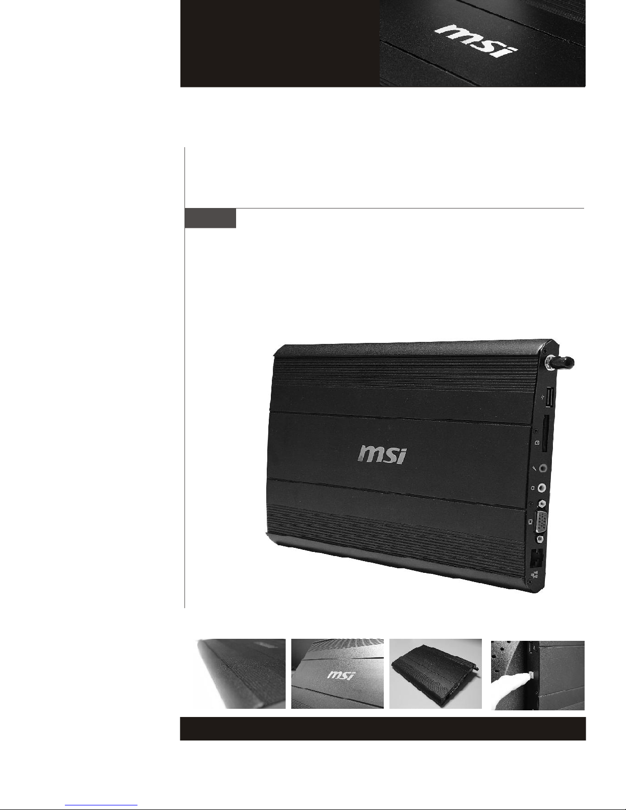
WindBOX Series
G52-9A151X1
i
Page 2

Copyright Notice
The material in this document is the intellectual property of MICRO-STAR
INTERNATIONAL. We take every care in the preparation of this document, but no
guarantee is given as to the correctness of its contents. Our products are under
continual improvement and we reserve the right to make changes without notice.
Trademarks
All trademarks are the properties of their respective owners.
Intel® and Pentium® are registered trademarks of Intel Corporation.
AMD®, Athlon™, Athlon™ XP, Thoroughbred™ and Duron™ are registered trademarks of AMD Corporation.
NVIDIA®, the NVIDIA logo, DualNet and nForce are registered trademarks or trademarks of NVIDIA Corporation in the United States and/ or other countries.
PS/2® and OS/2® are registered trademarks of International Business Machines
Corporation.
Windows® 95/ 98/ 2000/ NT/ XP/ VISTA are registered trademarks of Microsoft
Corporation.
Netware® is a registered trademark of Novell, Inc.
Award® is a registered trademark of Phoenix Technologies Ltd.
AMI® is a registered trademark of American Megatrends Inc.
U.S. Patent Numbers
4,631,603; 4,819,098; 4,907,093; 5,315,448; and 6,516,132.
This product incorporates copyright protection technology that is protected by U.S.
patents and other intellectual property rights. Use of this copyright protection technology must be authorized by Macrovision, and is intended for home and other limited
viewing uses only unless otherwise authorized by Macrovision. Reverse engineering or disassembly is prohibited.
Revision History
Revision Revision History Date
V1.0 First Release January 2009
Technical Support
If a problem arises with your system and no solution can be obtained from the user’s
manual, please contact your place of purchase or local distributor. Alternatively,
please try the following help resources for further guidance.
Visit the MSI website for FAQ, technical guide, BIOS updates, driver up-
dates and other information: http://global.msi.com.tw/index.php?
func=service
Contact our technical staff at: http://ocss.msi.com.tw
ii
Page 3
Safety Instructions
1. Always read the safety instructions carefully.
2. Keep this user’s manual for future reference.
3. Keep this equipment away from humidity.
4. Lay this equipment on a reliable flat surface before setting it up.
5. The openings on the enclosure are for air convection hence protects the
equipment from overheating. DO NOT COVER THE OPENINGS.
6. Check the AC input: 100-240V~, 50-60Hz, 1.7A.
7. Check the DC output: 20V 2.0A.
8. Make sure that the power voltage is within its safety range and has been
adjusted properly to the value of 100~240V before connecting the equipment
to the power inlet.
9. Place the power cord in a way that people are unlikely to step on it. Do not
place anything on the power cord.
10. Always unplug the power cord before inserting any add-on card or module.
11. All cautions and warnings on the equipment should be noted.
12. Never pour any liquid into the opening that could damage or cause electrical
shock.
13. If any of the following situations arises, get the equipment checked by service personnel:
The power cord or plug is damaged.
Liquid has penetrated into the equipment.
The equipment has been exposed to moisture.
The equipment does not work well or you can not get it work according to
user’s manual.
The equipment has dropped and damaged.
The equipment has obvious sign of breakage.
14. DO NOT LEAVE THIS EQUIPMENT IN AN ENVIRONMENT UNCONDITIONED,
STORAGE TEMPERATURE ABOVE 40o C (102oF), IT MAY DAMAGE THE
EQUIPMENT.
WARNING:
1. For every changes in power cord’s usage, please use an approved power
cord with condition greater or equal to H05VV-F, 3G, 0.75mm2.
2. Internal part is hazardous moving parts, please keep fingers and other body
parts away.
3. For pluggable equipment, the socket-outlet shall be installed near the equipment and shall be easily accessible.
4. Do not disable the protective earth pin from the plug, the equipment must be
connected to an earthed mains socket-outlet.
CAUTION:
Danger of explosion if battery is incorrectly replaced. Replace only with the same or
equivalent type recommended by the manufacturer.
廢電池請回收
For better environmental protection, waste batteries should be
collected separately for recycling or special disposal.
1. The optical storage devices are classified as a Class 1 Laser products.
Use of controls or adjustments or performance of procedures other
than those specified.
2. Do not touch the lens inside the drive.
iii
Page 4
FCC-B Radio Frequency Interference Statement
This equipment has been tested and
found to comply with the limits for a
Class B digital device, pursuant to Part
15 of the FCC Rules. These limits are
designed to provide reasonable protection against harmful interference in a residen-
tial installation. This equipment generates, uses and can radiate radio frequency
energy and, if not installed and used in accordance with the instruction manual, may
cause harmful interference to radio communications. However, there is no guaran-
tee that interference will not occur in a particular installation. If this equipment does
cause harmful interference to radio or television reception, which can be determined
by turning the equipment off and on, the user is encouraged to try to correct the
interference by one or more of the measures listed below:
Reorient or relocate the receiving antenna.
Increase the separation between the equipment and receiver.
Connect the equipment into an outlet on a circuit different from that to
which the receiver is connected.
Consult the dealer or an experienced radio/television technician for help.
Notice 1
The changes or modifications not expressly approved by the party responsible for
compliance could void the user’s authority to operate the equipment.
Notice 2
Shielded interface cables and A.C. power cord, if any, must be used in order to
comply with the emission limits.
VOIR LA NOTICE D’INSTALLATION AVANT DE RACCORDER AU RESEAU.
Micro-Star International
WindBOX Series
This device complies with Part 15 of the FCC Rules. Operation is subject to the
following two conditions:
(1) this device may not cause harmful interference, and
(2) this device must accept any interference received, including interference that
may cause undesired operation.
iv
Page 5
WEEE (Waste Electrical and Electronic Equipment) Statement
v
Page 6
vi
Page 7
vii
Page 8

CONTENTS
Copyright Notice...........................................................................................ii
Trademarks..................................................................................................ii
U.S. Patent Numbers....................................................................................ii
Revision History...........................................................................................ii
Technical Support........................................................................................ii
Safety Instruction.........................................................................................iii
FCC-B Radio Frequency Interference Statement....................................iv
WEEE (Waste Electrical and Electronic Equipment) Statement..............v
Chapter 1 Getting Started...........................................................................1-1
System Specifications.....................................................................................1-2
System Outlooks..............................................................................................1-4
Packing Contents.............................................................................................1-6
Chapter 2 System Assembly.....................................................................2-1
Necessary Tools..............................................................................................2-2
Assembly Porcedures.....................................................................................2-2
viii
Page 9
Getting Started
Chapter 1
Getting Started
Congratulations for purchasing the WindBOX. This is
your best choice for slim system. It can easily be set
anywhere. The feature packed platform also gives you
an exciting PC experience.
1-1
Page 10
WindBOX Series
System Specifications
Processor
- Intel® AtomTM processor N270
- Front Side Bus (FSB) 533 MHz
- Thermal Design Power (TDP) 2.5 W
- Highest Frequency Mode (HFM) 1.6 GHz
- Lowest Frequency Mode (LFM) 800 MHz
Chipset
- North Bridge: Intel® 945GSE chipset
- South Bridge: Intel® ICH7M chipset
Display
- Intel® GMA 950 chipset
- Resolution is up to QXGA (2048 x 1536)
Memory
- Supports DDR2 400/ 533 SDRAM (200-Pin/ 1.8 V)
- 1 DDR2 SO-DIMM slot (1 GB Max) (Non-ECC)
Audio
- Chip integrated by Realtek® ALC888S
- HD audio Codec with auto jack sensing
LAN
- Supports 10/100 Fast Ethernet by Realtek® RTL8102E
- Compliant with PCI 2.3
- Supports ACPI Power Management
1-2
Page 11
Input/ Output (I/O)
- 3 USB 2.0 ports
- 1 Headphone / speaker connector (3.5mm)
- 1 Mic connector (3.5mm)
- 1 VGA connector
- 1 RJ-45 LAN jack (by Realtek RTL8185E)
- 1 3-in-l card reader (SD/MMC/MS)
- 1 DC jack
- 1 SMA connector for WLAN antenna
Power Supply
- 40 Watt Power Adapter with Active PFC
- Input: 100-240V~, 50-60Hz 1.7A
- Output: 20V, 2.0A
Getting Started
Form Factor
- 260 mm (W) X 180 mm (D) X 19 mm (H)
- 1.08 Kg
Operation Environment
- Temperature: 0oC ~ 35oC
- Humidity: 5% ~ 90% (non condensing)
Storage Environment
- Temperature: -20oC ~ 80oC
- Humidity: 5% ~ 90% (non condensing)
1-3
Page 12
WindBOX Series
System Outlooks
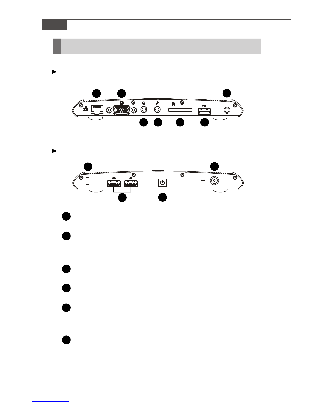
Right Side View
1
Left Side View
8
1
2
RJ-45 Connector
The connector is used to connect a LAN cable for network connection.
VGA Port
The 15-pin-D-sub VGA port allows you to connect an external monitor or
other standard VGA-compatible device (such as a projector) for a great
view of the computer display.
2 7
6543
10
6
9
3
4
5
6
1-4
Headphone
Used for speakers or headphones.
Microphone
Used for an external microphone.
Card Reader
The built-in card reader may support various types of memory card, such
as MMC (Multi-Media Card), SD (Secure Digital), MS (Memory Stick) or
cards.
USB Port
The USB 2.0 port allows you to connect USB-interface peripheral devices,
such as the mouse, keyboard, modem, portable hard disk module, printer
and more.
Page 13

Getting Started
7
8
9
10
Antenna Connector
The connector allows you to connect an external antenna for wireless
LAN.
Kensington Lock
This system provides a Kensington Lock hole, which allows users to
secure the system in place with a key or some mechanical PIN device and
attached through a rubberised metal cable. The end of the cable has a
small loop which allows the whole cable to be looped around a permanent
object, such as a heavy table or other similar equipment, thus securing
the system in place.
Power Button
Press the power button to turn the system power ON and OFF.
Power Connector
Connect the adapter and supply power for the system.
1-5
Page 14
WindBOX Series
Packing Contents
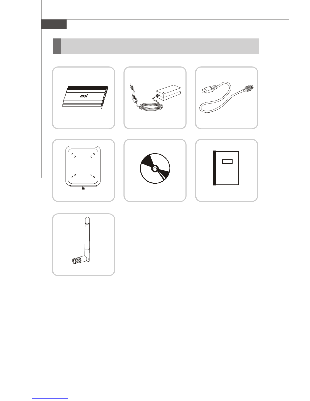
WindBOX Power Adapter Power Cord
Driver CDBack Mount Package
User Manual
WLAN Antenna
* Please contact us immediately if any of the item is damaged or missing.
* The picture is for your reference only and your packing contents may slightly vary
depending on the model you purchased.
1-6
Page 15
System Assembly
Chapter 2
System Assembly
This chapter provides you with the information about
system assembly procedures. While doing the
installation, be careful in holding the components and
follow the installation procedures.
Use a grounded wrist strap before handling computer
components. Static electricity may damage the
components.
2-1
Page 16
WindBOX Series
Necessary Tools
Cross type screwdriver, can be used to do most of the
installation. Choose one with a magnetic head would be
better.
Rubber gloves, can prevent yourself from suffering the
static charge.
Assembly Procedures
Important
Choose the LCD less than 5.8 Kg for keeping the weight balance; otherwise,
it may cause fall or related hazard.
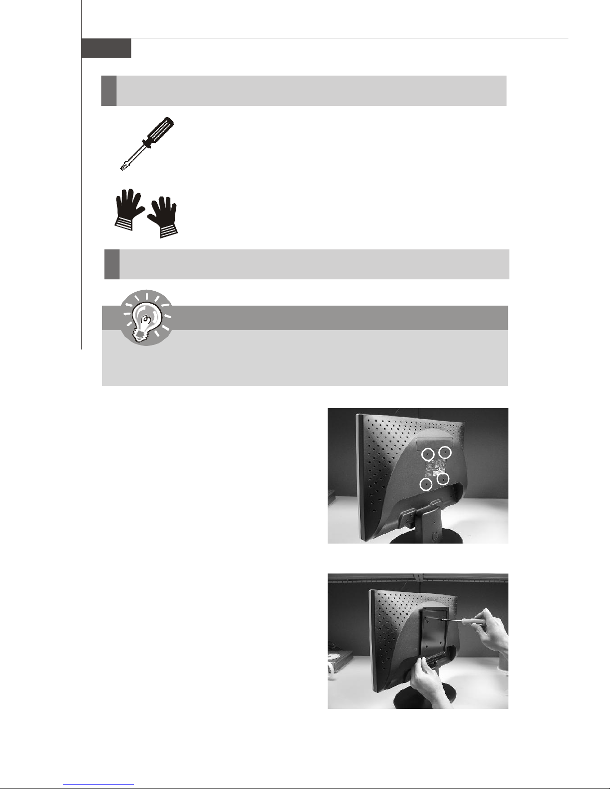
1. Find the screw holes on the back of
the LCD.
2. Use the corss-type screwdriver to
fix the back mount plate with the
attached screws.
2-2
Page 17
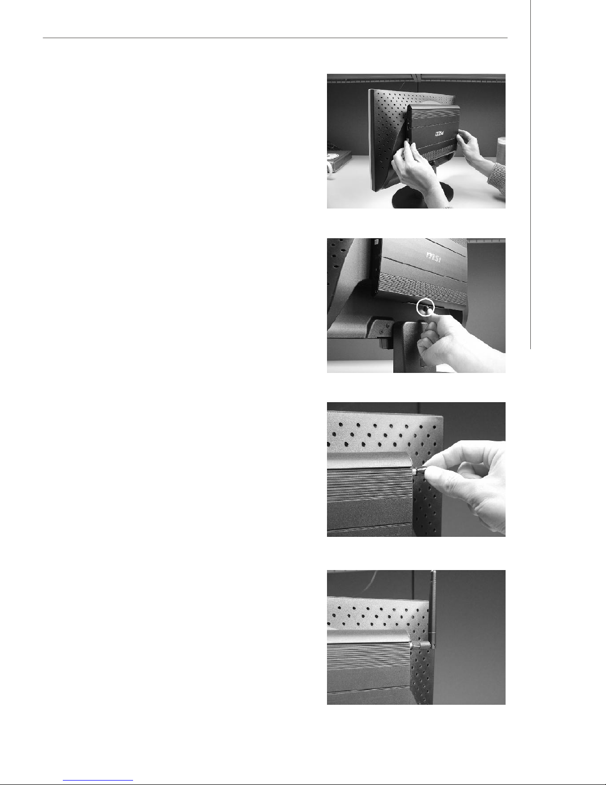
3. Hang the system on the back mount
plate.
4. The screw on the bottom of the
back mount plate can be used to
fasten the system.
System Assembly
5. Remove the protector from the
WLAN antenna connector.
6. Install the attached WLAN antenna.
2-3
Page 18
WindBOX Series
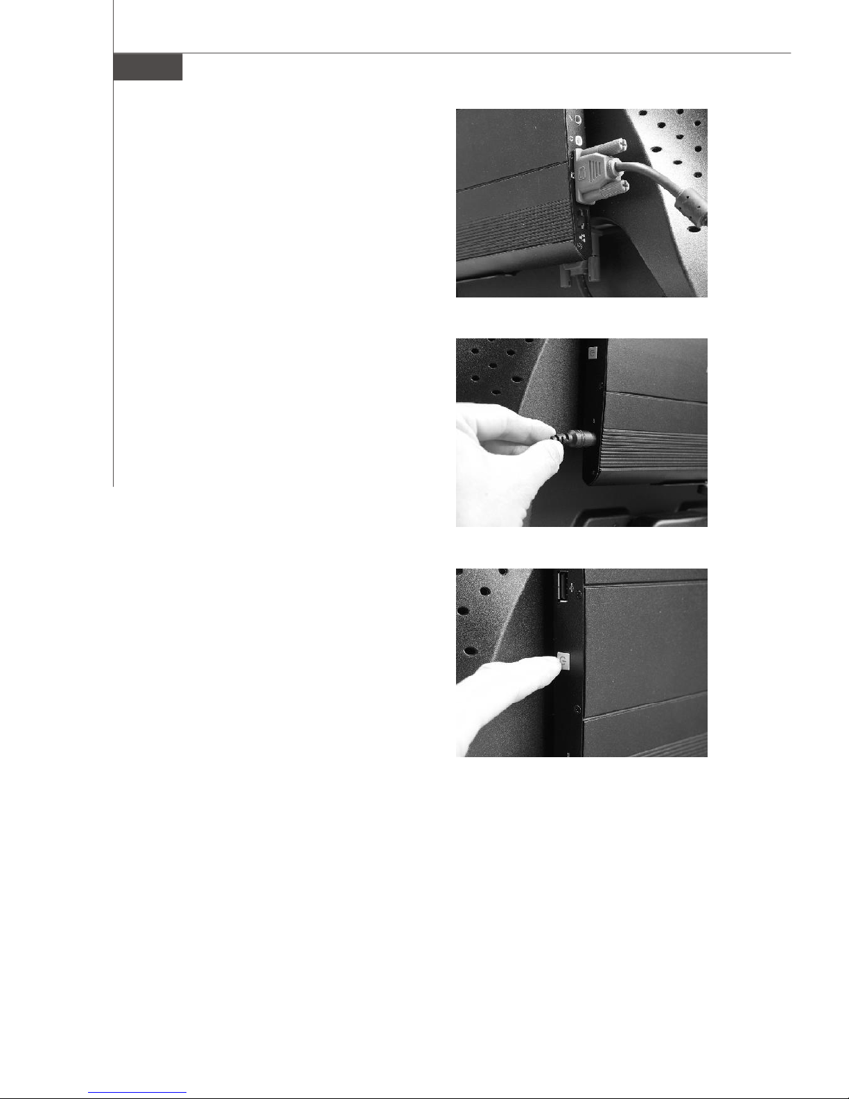
7. Connect the VGA cable between
the system and the LCD.
8. Connect the adaptor the the system.
9. Turn on the system and enjoy it.
2-4
 Loading...