

Page 1
U
SER’S
G
TV series
based on ATi chipset
UIDE
Version 3.0
July 2007
G52-V1TVX06
i
Page 2
FCC-B Radio Frequency Interference Statement
This equipment has been tested and found to comply with the limits for a class B
digital device, pursuant to part 15 of the FCC rules. These limits are designed to
provide reasonable protection against harmful interference when the equipment
is operated in a commercial environment. This equipment generates, uses and
can radiate radio frequency energy and, if not installed and used in accordance
with the instruction manual, may cause harmful interference to radio
communications. Operation of this equipment in a residential area is likely to
cause harmful interference, in which case the user will be required to correct
the interference at his own expense.
Notice 1
The changes or modifications not expressly approved by the party responsible
for compliance could void the user’s authority to operate the equipment.
Notice 2
Shielded interface cables and A.C. power cord, if any, must be used in order to
comply with the emission limits.
VOIR LA NOTICE D’INSTALLATION AVANT DE RACCORDER AU RESEAU.
This device complies with Part 15 of the FCC Rules. Operation is subject to the
following two conditions:
(1)this device may not cause harmful interference, and
(2)this device must accept any interference received, including interference
that may cause undesired operation.
ii
Micro Star International
MS-8632
Page 3

Copyright Notice
The material in this document is the intellectual property of MICRO-STAR
INTERNATIONAL. We take every care in the preparation of this document, but
no guarantee is given as to the correctness of its contents. Our products are
under continual improvement and we reserve the right to make changes without
notice.
Trademarks
All trademarks are the properties of their respective owners.
† Intel
† Windows
Macrovision Corporation Product Notice
This product incorporates copyright protection technology that is protected by
method claims of certain U.S. patents and other intellectual property rights owned
by Macrovision Corporation and other right owners. Use of this copyright protection technology must be authorized by Macrovision Corporation, and is in-
tended for home and other limited viewing uses only unless otherwise author-
ized by Macrovision Corporation. Reverse engineering or disassembly is
prohibited.
®
and Pentium® are registered trademarks of Intel Corporation.
®
Vista/ XP/ MCE are registered trademarks of Microsoft
Corporation.
iii
Page 4

Important Safety Precautions
Always read and follow these basic safety precautions carefully when
handling any piece of electronic component.
1. Keep this User’s Manual for future reference.
2. Keep this equipment away from humidity.
3. Lay this equipment on a stable, flat surface before setting it up.
4. The openings on the enclosure are for air convection, hence they protect
the equipment from overheating.
5. Make sure the voltage of the power source and adjust properly 110/220V
before connecting the equipment to the power inlet.
6. Place the power cord in a way that people are unlikely to step on it. Do
not place anything on the power cord.
7. Always Unplug the Power Cord before inserting any add-on card or
module.
8. All cautions and warnings on the equipment should be noted.
9. Never pour any liquid into the opening that could damage the
equipment or cause an electrical shock.
10.If any of the following situations arise, get the equipment checked by a
service personnel:
The power cord or plug is damaged.
Liquid has penetrated into the equipment.
The equipment has been exposed to moisture.
The equipment has not functioned properly or in accordance with
the User’ s Guide.
The equipment was dropped and damaged.
The equipment has obvious signs of breakage.
11.DO NOT LEAVE THE EQUIPMENT IN AN UNCONDITIONED ENVIRONMENT
WITH A STORAGE TEMPERATURE OF 60o C (140oF) OR ABOVE. IT MAY
DAMAGE THE EQUIPMENT.
iv
Page 5

CONT E NTS
Chapter 1 GETTING STARTED..........................................................1-1
1.1 How to Use this Guide...............................................................1-2
Chapter 2 INTRODUCTION................................................................2-1
2.1 Product Introduction...................................................................2-2
Chapter 3 HARDWARE INSTALLATION............................................3-1
3.1 Card Installation.........................................................................3-2
Chapter 4 SOFTWARE INSTALLATION............................................4-1
4.1Installing the TV Tuner Card Driver............................................4-2
4.2 Vista Remote Control and Receivor..........................................4-3
4.3 Microsoft Media Center...............................................................4-4
Setup for Watching Analog TV....................................................4-4
Setup for Watching Digital TV (ATSC)........................................4-6
4.2Installing the Bundled Software.................................................4-9
Installing PowerCinema............................................................4-9
Installing Power2Go.................................................................4-11
Installing MakeDisc..................................................................4-13
4.5PowerCinema Settings...........................................................4-14
PowerCinema Introduction.....................................................4-14
PowerCinema Setup Wizard...................................................4-14
PowerCinema Settings...........................................................4-15
4.6Operating PowerCinema........................................................4-18
TV Function...............................................................................4-18
Movies Function.......................................................................4-25
Video Function.........................................................................4-27
Music Function.........................................................................4-29
Pictures Function.....................................................................4-33
Radio Function.........................................................................4-36
Extras........................................................................................4-39
MakeDisc Function...................................................................4-40
4.7Using Power2Go.....................................................................4-41
v
Page 6

Νοτε
vi
Page 7

1
GETTING ST ARTED
This user’s guide is designed for a series of TV
tuner cards. Read this chapter first, and it will give
you a clear instruction on how to use this guide.
1-1
Page 8

Chapter 1
1.1 How to Use this Guide
This user’s guide is designed for a series of TV tuner cards. Before you
start reading this guide, find out the product name of the TV tuner card
you have just purchased on the gift box, and look for the specification
and function description in next chapter in accordance with the product
name of your TV tuner card .
Chapter 2, INTRODUCTION, provides the brief specification and function of each TV tuner card. For detailed description of all functions, you
may refer to the rest of the chapters. Note that the TV tuner card you
purchased may not cover all functions mentioned herein; therefore, it is
recommended to read the “Reference” information first, which indexes
the correspoding founction description of each different TV tuner card,
and then find the proper function de scri ption f or your TV tuner card in the
other chapters.
Chapter 3, HARDWARE INSTALLATION, tells you how to install your TV
tuner card into your computer correctly, and the function of each connector on the VGA card. Also note that your TV tuner card may not cover all
functions mentioned in this chapter. Check on Chapter 2,
INTRODUCTION, for the specification of the TV tuner card you purchased if you have any problem finding the proper function description
for your card.
Chapter 4, SOFTW ARE INSTALLATION, describes how to install MSI TV
tuner card software for Windows XP, including the driver and useful
utilities.
1-2
Page 9

2
INTRODUCTION
This chapter provides some brief specification and
function of each TV tuner card. For detailed description of all functions, you may need to refer to
the other cha pters. Note that the TV tuner card you
purchased may not cover all functions mentioned
herein; therefore, it is recommended that you read
the “Reference” information first, which indexes
the correspoding founction description to each different TV tuner card, and then find the proper function description for your TV tuner card in other
chapters.
2-1
Page 10
Chapter 2
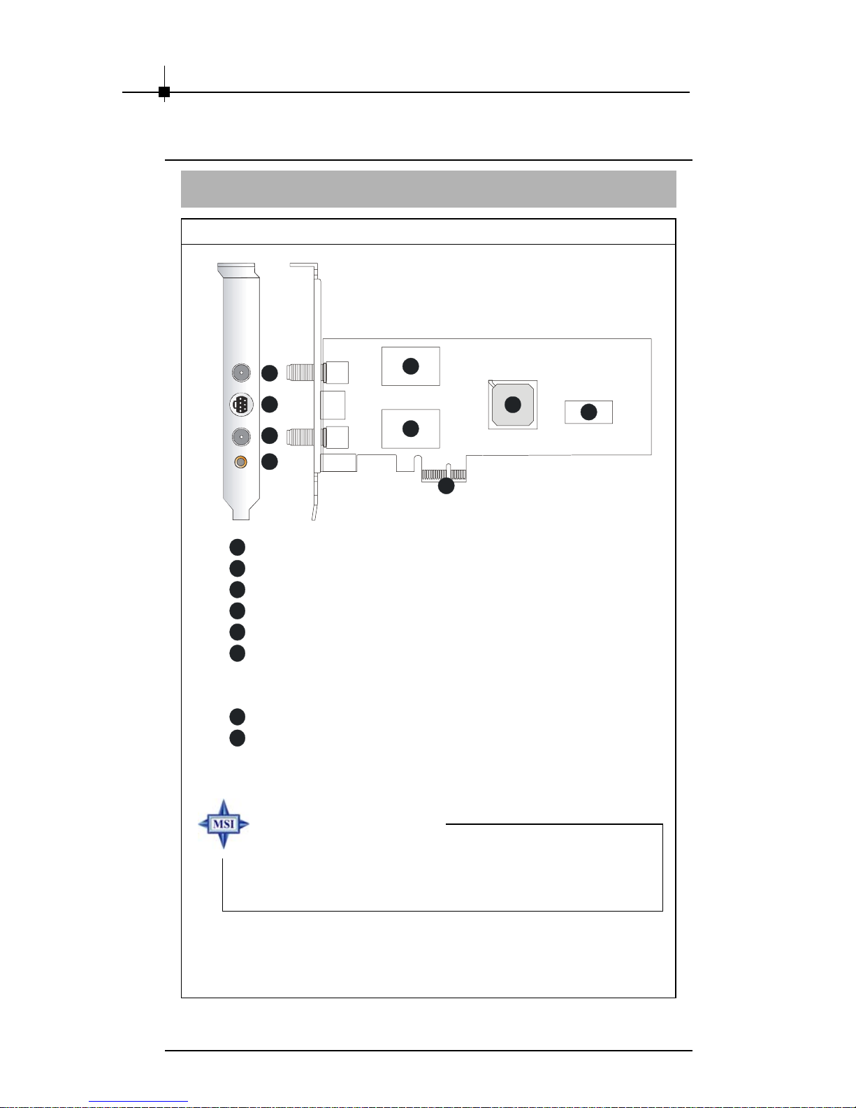
2.2 Product Introduction
THEATERTM 650 PRO
Layout
5
6
7
8
1
A Ti THEA TER 650 PRO GPU
2
16MB DDR RAM
3
Sa msung Tuner
4
PCI Express x1 Interface
5
Digital (ATSC) & FM Antenna Connector
6
Video Input Connector
3
3
4
- S-Video
- Composite
7
Analog TV Cable Connector
8
Audio Input Connector
1
2
MSI reminds you...
Note that the TV tuner card shown above may vary from the
actual card. For further information, please visit MSI
website at http://www.msi.com.tw
2-2
Page 11

Introduction
Features
z Watch digital ATSC T V & analog TV (NTSC)/ video simultaneously.
z Worldwide Audio Decoder (Stereo & SAP)
z Built in MPEG2 hardware encoder
z HDTV 1080i ready (for ATSC TV only)
z Time Shifting/ Scheduled Recording
z FM Radio reception
z Powerful 12-bits video engine and Motion adaptive 3D Comb Filter
z PCI-Express
z Additional AV/ S-Video Input for connecting other Video Sources.
®
1X bus interface
(Such as DVD Player/ VCD/ VHS/ Camcorder)
z Windows Vista Certificated.
Technical Specs
z 125 channel TV tuner with stereo audio.
z ATSC digital TV support
z New worldwide video decoder, NTSC, PAL, SECAM support
5-line 2D comb filter
Motion adaptive 3D comb filter
z Hardware MPEG compression engine
MPEG-2 720x480 compression
CBR and VBR from 1 to 15 Mbps
z Worldwide audio decoder
z 3:2 pull-down
z Motion compensated noise reduction
z Edge enhancement
z FM Radio reception
z Digital audio processing
z VBI slicing
z Audio/video input support
z PCI-Express
®
1X bus interface
2-3
Page 12

Chapter 2
TV -Tuner Require ments
z TV signal from amplified antenna or cable Versions available for:
NTSC (North America, Japan, Taiwan, Korea and Latin America)/
NTSC/ ATSC (North America, parts of Latin America).
z Features may vary from country to country and depending on the
television standard.
System Requirements
z Pentium 4 CPU 2.0GHz or above
z 256MB RAM of system memory or above
z Motherboard with PCI Express
z Graphics Card (Must support Microsoft
z Sound Card (AC97 compatible sound card)
z 2GB Free HD Space for recording
z CD-ROM Driver (For software installation)
z Microsoft
z Microsoft
z Outdoor antenna TV connection for ATSC
z Outdoor antenna/ cable TV connection for Analog TV
®
Direct®X 9.0c
®
Windows® XP(SP2) / Vista
®
Direct®X 9.0 or above)
2-4
Page 13
Introduction
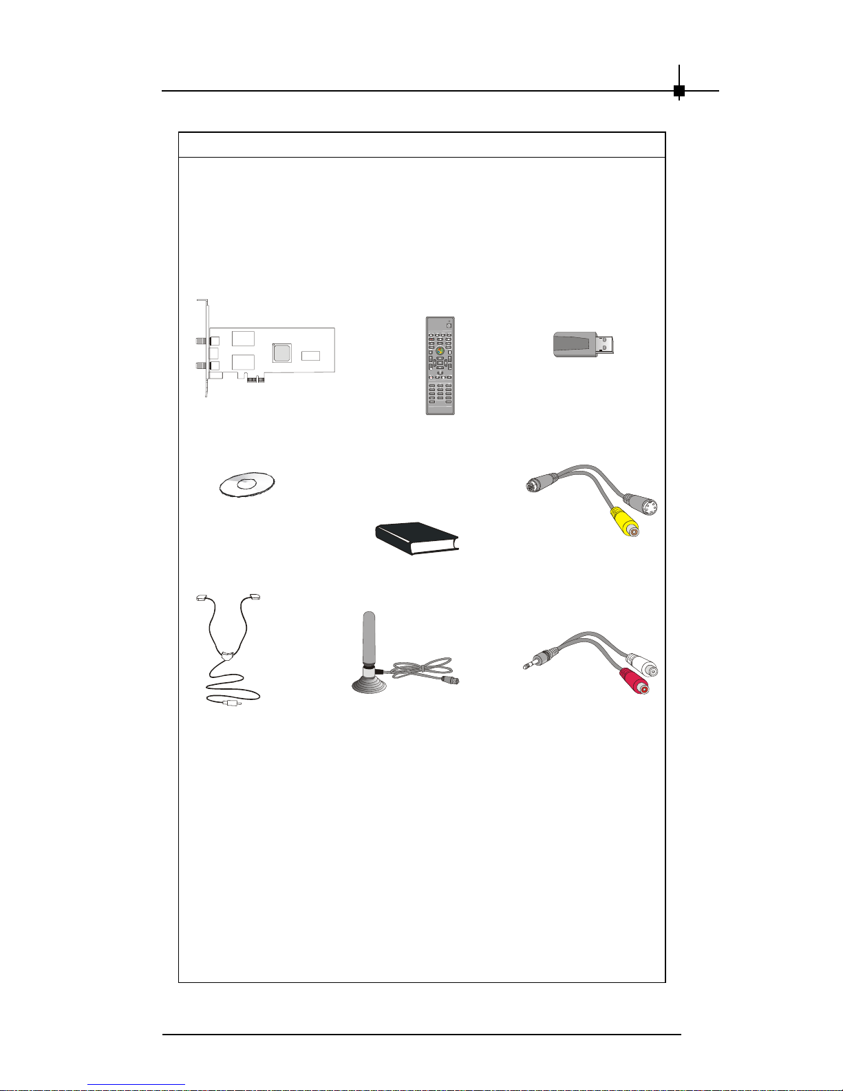
Package Contents
Unpack the package and inspect all the items carefully. If any item
contained is damaged or missing, please contact your local dealer as
soon as possible. Also, keep the box and packing materials in case you
need to ship the unit in the future.
Your TV tuner card package should contain the following items:
THEATERTM 650 PRO
Software Pack CD*
FM Radio
Antenna
2
1
5
4
8
7
0
Remote Control
User’ s Guide
ATSC Antenn a**
Remote Receiver
3
6
9
#
Video Cable
Audio Cable
* Includes MAGIX Goya Base software. Goya Base is XP, MCE 2005 and Vista
compatible. Some functions are unavailable; upgrade to MAGIX Goya Multimedia
for more functions.
** The included antenna is only suitable for areas with a strong ATSC signal. If you
have reception problems, first try to move or reorient the antenna. Otherwise, you
may need to use a stronger antenna for better reception.
2-5
Page 14

Νοτε
vi
Page 15

3
HARDWARE
INSTALLATION
This chapter tells you how to install your card into
your computer correctly and how to use the connectors on the card. Note that your card may not
cover all functions mentioned in this chapter. Check
on Chapter 2, INTRODUCTION, for the specification of the card you purchased if you have any problem in finding the proper function description for
your card.
3-1
Page 16
Chapter 3
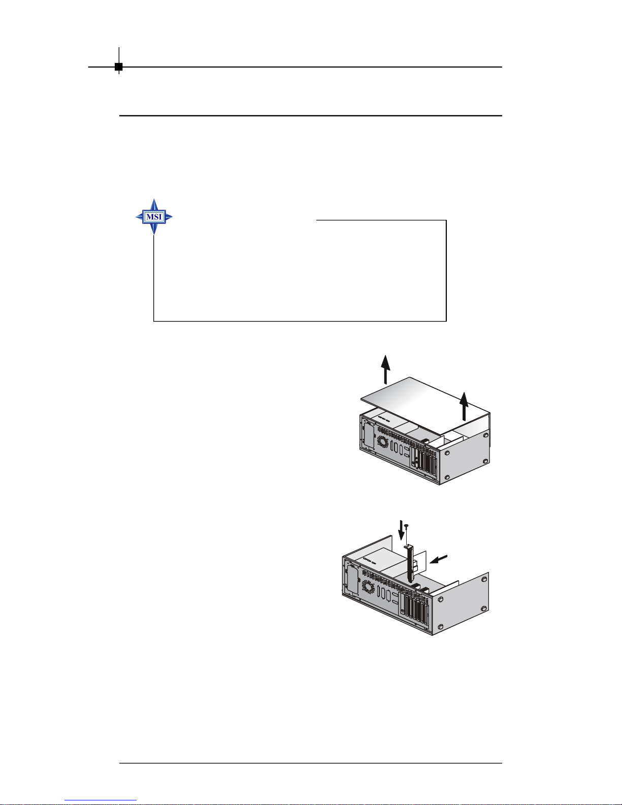
3.1 Card Installation
To install the card into your computer, please follow the steps below:
1. Follow the Windows® shut down procedure to turn off your
computer.
MSI reminds you...
Warning: Always remember to turn off your computer
before installing or removing hardware to or from your
computer. Neither the manufacturer nor the dealer is
responsible for damages if the user ignores this
warning!!!
2. Remove the cover from your
computer.
3. Put the card over an PCI Express
slot, and then press one end of
the card into the slot first. Gently
but firmly press the other end
until it is fully seated in the slot.
Secure the card with a bracket
screw.
3-2
Page 17
Hardware Installation
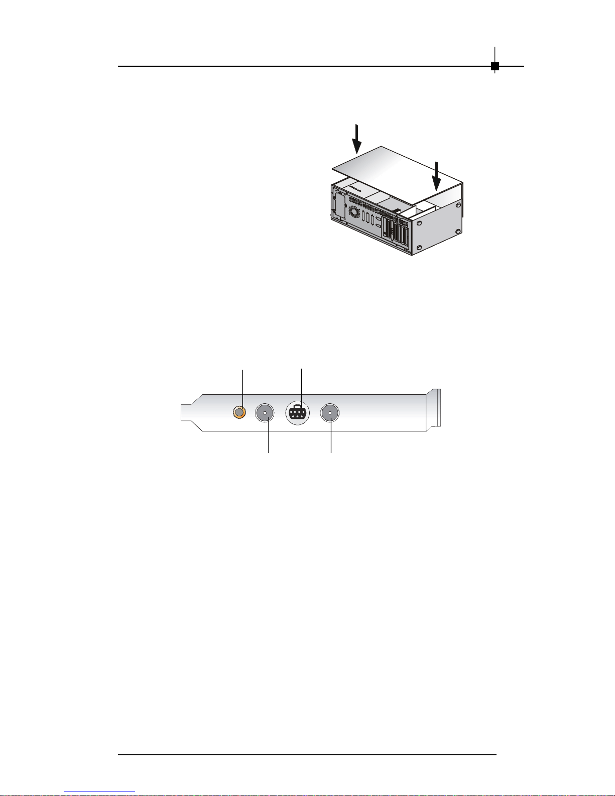
4. Install the computer cover.
5. Connect the necessary cables to meet your usage.
S-Video Cable/
Composite Cable
Audio Cable Connector
Connector
Analog TV Cable
Connector
ATSC Antenna/ FM Radio
Antenna Connector
3-3
Page 18

Chapter 3
Νοτε
3-4
Page 19

4
SOFTWARE
INSTALLATION
This chapter describes how to install software
under Windows® Vista, including the drivers and
useful utilities.
3-1
Page 20

Chapter 4
4.1 Installing the TV Tuner Card Driver
After intalling the TV Tuner card to your system, follow the steps below to install
the driver before activating and operating with it.
Note: The following figures and descriptions are for computers with
Windows® Vista. There might be slightly differences for Windows® XP
system.
1. Turn on the computer.
2. Insert the provided CD into the CD-ROM drive. The autorun program will start
the setup program.
3. Click Install THEATER 650PRO Driver. The following figure will show on the
screen.
4. Follow the on-screen instructions to continue the installation.
4-2
Page 21

Software Installation
4.2 Vista Remote Control and Receivor
In the packing, you can find a remote control and a receivor. They are for
you to control Vista system.
Buttons & Definitions
1. Receivor: Connect to a USB port of a Vista system to
receive the remote control signal.
2. Signal LED: This LED shines when the remote sends
control signal.
3. Power Button: Press to let system enter Sleep mode.
4. Picture Button: Press to start Picture function.
5. Radio Button: Press to start Radio function.
6. Video Button: Press to start Video function.
7. Music Button: Press to start Music function.
8. Record Button: Press to record the TV program you are
watching.
9. Pause Button: Press to stop the on going function
temporarily; press Play to continue.
10. Stop Button: Press to stop the on going function;
press Play to start from the beginning.
11. Skip Back Button: Jump back to the previous one.
12. Play Button: Press to run the function you select.
13. Skip Fwd Button: Jump to the next one.
14. Rew Button: Move backward.
15. Fwd Button: Move forward.
16. Vista Button: Start Windows Media Center.
17. Back Button: Go back to the upper function group.
18. Info Button: Provide information of current status.
19. Volume +/-: Tune the volume up/down.
20. Channel +/-: Change the channel.
21. Up Button: Move to the up side.
22. Down Button: Move to the down side.
23. Left Button: Move to the left side.
24. Right Button: Move to the right side.
25. OK Button: Run the current pointed function.
26. Mute: Turn off the volume immediately.
27. Recorded TV: Start the Recorded TV function.
28. Guide Button: Start the Guide function.
29. Live TV: Start the TV.
30. DVD Menu: Open the DVD menu.
31. Number Keys: Enter channel number or other digit.
32. Clear Button: Clear what you just input/choose.
33. Enter Button: Confirm what you just input.
Connect and Use
Connect the receivor to a USB port of a Vista system. The system will
autodetect it and intall its driver automatically. Point the remote toward the
receivor and press a needed button, the system will act appropriately.
Note: this remote can work on a PC with Vista or MCE operation system.
Note: install 2 AAA batteries to the remote control before using. If the signal
LED does not shine while pressing buttons, replace the batteries.
4-3
Page 22

Chapter 4
4.3 Microsoft Media Center
On the Windows system bundled Microsoft® Media Center, you can use the
Media Center program to watch and record TV shows, enjoy your photos in a
cinematic slide show, browse your music collection by cover art, easily play
DVDs, etc.
Setup for Watching Analog TV
1. Connect the analog TV cable to the TVIN connector on the TV card. Select
Task menu, and select Settings.
2. Select TV option on the Settings menu and enter. Click Yes on the TV
SIGNAL SETUP pop-up window.
4-4
Page 23

Software Installation
3. On Set Up Your TV Signal window, click on Next. Click on “Yes, use
this region to configure TV services”, and click on Next to continue. Click
on “No, I want to select a different region” and click Next if the region is
not correct.
4. Select “Cable” from the 3 options and click on Next. Then select No and
Next on Do You Have a Set-top Box? window.
5. Select “Return to TV Settings” and click Finish on You Are Done!
window. Then you can go to live tv function to enjoy watching analog TV.
4-5
Page 24

Chapter 4
Setup for Watching Digital TV (ATSC)
1. Connect the Digital TV antenna to the ANTIN connector on the TV card.
Select Task menu, and select Settings.
2. Select TV option on the Settings menu and enter. Click Yes on the TV
SIGNAL SETUP pop-up window.
3. On Set Up Your TV Signal window, click on Next. Click on “Yes, use
this region to configure TV services”, and click on Next to continue. Click
on “No, I want to select a different region” and click Next if the region is
not correct.
4-6
Page 25

Software Installation
4. Select “ Antenna” option and click on Next. Then select “Analog-only
antenna” and Next on Select Your TV Signal Type window.
5. Select “Return to TV Settings” and click Finish on You Are Done!
window.
6. Go back to previous menu, select “” option and click on Next. Click Yes on
the TV SIGNAL SETUP pop-up window.
4-7
Page 26

Chapter 4
7. You will see the Scan for Services window, available channels will be
listed below when searched. Click Next to continue after the procedure is
done. Select “Return to TV Settings” and click Finish on You Are Done!
window. Then you can go to live tv function to enjoy watching Digital TV.
Note: for informaiton of other functions on Media Center, please refer to the
Windows Help and Support or visit Microsoft website.
4-8
Page 27

Software Installation
4.4 Installing the Bundled Software
Installing PowerCinema
PowerCinema delivers a total digital home entertainment solution for music,
videos, pictures, and DVD movies. Also watch and record TV, and listen to
radio from your PC via the installed TV Tuner card.
1. Insert the provided CD into the CDROM drive. The autorun program
will start the setup program.
2. Click Install PowerCinema.
Note: PowerCinema supports
Windows XP and Vista operating system.
3. Select the language for this
installation. And you will see the
progress bar.
4. In seconds, the Wizard will be
ready. Follow the InstallShield
Wizard for PowerCinema.
5. Enter user’s information and serial
number.
Note: The CD-Key number will
be detected by the system
automatically.
4-9
Page 28

Chapter 4
6. Select a target folder to install files.
If there is no need to change, click
Next to continue.
7. The utility will be installed with the
default folder name, CyberLink
PowerCinema. You can enter a
preferred name for it. Click Next to
continue.
8. PowerCinema Setup is performing
the requested operations.
9. Click Finish to exit the wizard.
4-10
Page 29

Software Installation
Installing Power2Go
Power2Go is a complete and powerful burning software for burning data,
music, videos and photos onto CDs, DVDs, Blu-ray Discs(BD) and HD DVDs.
1. Insert the provided CD into the CDROM drive. The autorun program
will start the setup program.
2. Click Install Power2Go.
Note: Support Windows XP and
Vista operating system.
3. Select the language for this
installation. And you will see the
progress bar.
4. Follow the InstallShield Wizard for
Power2Go.
4-11
Page 30

Chapter 4
5. Enter user’s information, and click
Next to continue.
6. Select the folder where Setup will
install files.
7. Click Next to continue. Then the
Power2Go Setup performs the
requested operations.
8. Select the check box next to “View
the Readme file” before clicking
Finish to exit the wizard if you
want to read the Readme file.
4-12
Page 31

Software Installation
Installing MakeDisc
MakeDisc is a plugin of PowerCinema. Install it after PowerCinema, then you
can create movie DVD/VCD and music VCD or other discs containing video or
music content.
1. Insert the provided CD into the CDROM drive. The autorun program
will start the setup program.
2. Click Install MakeDisc.
Note: Support Windows XP
and Vista operating system.
3. Select the language for this
installation. And you will see the
progress bar.
4. In seconds, the Wizard will be
ready. Follow the InstallShield
Wizard for MakeDisc.
5. Click Finish to exit the wizard.
4-13
Page 32

Chapter 4
4.5 PowerCinema Settings
PowerCinema Introduction
PowerCinema is an integrated multimedia player. The Home page displays the
available media types, which you can browse through using the Right/ Left
buttons on the remote controller*, a mouse scroll wheel, and the keyboard
right/ left arrows. While the needed function shows in the middle of display,
press Enter key or click on the figure to enter its sub-menu.
The navigation bar at the top of the window contains Home and Back buttons.
Select the Home icon to return to the Home page. Select the Back icon to
return to a previous page.
* Please read Page 4-3 to find the the information of the remote controller in
details.
Note that while watching videos, DVDs, or slideshows, your screensaver and
the monitor-off power-saving function will not be available. However, both of
these functions will be enabled when you listen to music.
PowerCinema Setup Wizard
After installing the PowerCinema software, you will see the following figure at
the first time executing it. The PowerCinema Setup Wizard guides you to optimize
your computer before operating. Click Next and follow the further instructions to
complete the optimization procedures.
4-14
Page 33

Software Installation
PowerCinema Settings
Select and enter Settings on the Home page.
General Settings
At the right hand side of PowerCinema Settings submenu, you can read
several geneal items:
PowerCinema Help: opens the help system.
Display Settings: opens a page with options for configuring display
device.
Audio Settings: opens a page with options for configuring computer
audio.
Language Settings: allows you to change the display language of
PowerCinema. The language display will change dynamically, do not have
to restart the program.
Run Setup Wizard: opens the wizard that appears at the first time you
run PowerCinema, to optimize computer if you did not do so after
installation, or if the computer device has been replaced.
About PowerCinema: opens a page with version and copyright
information.
After making changes, click Apply to save and exit to previous page. Or click
Cancel to go back without making changes.
Note: Other settings can be found in the function-specific help sections.
4-15
Page 34

Chapter 4
Display Settings
Click on the Display Settings button on the settings menu to enter display
setting menu.
Use the Screen Ratio to indicate if you have a standard (4:3) or widescreen
(16:9) display.
16:9 (or 4:3) Movie Display Type determines how movies and videos are
converted to fit the screen when they do not match the screen ratio.
Letterbox keeps the video display undistorted and fills the extra space with
black bars. CLPV is a video stretching technology that produces minimal
distortion in the center of the picture. Pan & Scan displays the central portion
of DVD titles in widescreen ratio, and allows you to drag the display area to
view different portions of the video.
Color Profile allows you to change the overall color scheme of video
content during playback. Original uses the color scheme of the disc you are
watching. Vivid, Bright, and Theater add enhanced color to the video
display. CLEV-2 is a video enhancement technology that dynamically adjusts
the brightness, contrast, and saturation if the movie you are watching
contains scenes that are overly dark or bright. Options other than Original
require more system resources to run.
Style allows you to select the menu style on the home page. Choose between the standard menu and the circular menu. The Skin Color option
allows you to change the skin color of PowerCinema. The Visual Effect
option lets you choose between 2D and 3D effects in PowerCinema. Select
Good or Best for 3D effects, or Off for 2D effects.
Note: If your display card does not support 3D graphics, this option will
not be available. PowerCinema automatically detects your display card
capability.
Load Default Settings returns the settings on this page to their original
values.
After making changes, click Apply to save and exit to previous page. Or click
Cancel to go back without making changes.
4-16
Page 35

Software Installation
Audio Settings
Click on the Audio Settings button on the settings menu to enter audio
setting menu.
Set Speaker Environment to match the number of speakers you have.
Select SPDIF for digital audio output.
Output Mode determines the special processing used on the audio signal.
Experiment with the available settings to decide which you prefer.
Audio Channel Expander expands the range of sound of 4 or 6 speaker
output. CLMEI 2 is an audio channel expansion technology that converts
stereo audio sound and outputs it to multiple channels. There are three
variations: CLMEI 2 - Movie for watching movies, CLMEI 2 - Music for
regular music output, and CLMEI 2 - Onstage for a more live sound.
Dynamic Range Compression offers options for different listening
environments. Normal Environment creates a standard virtual listening
environment. Quiet Environment emphasizes even the slightest sound
effect in a movie. Noisy Environment amplifies low range audio signals,
which is especially suitable for notebook computers.
Load Default Settings returns the settings on this page to their original
values.
After making changes, click Apply to save and exit to previous page. Or click
Cancel to go back without making changes.
Other Settings
For the TV, Movies, Video, Music, Pictures, Radio settings, please refer to the
related following chapters.
4-17
Page 36

Chapter 4
4.6 Operating PowerCinema
TV Function
PowerCinema allows you to watch TV on your computer. You can watch TV
programs, schedule recordings and watch recorded TV shows. Select TV on
the Home page to open the main TV page.
Watching TV
When you watch TV, the following additional buttons appear on the playback
controls for use with a mouse: Channel up (switches up one channel),
Channel down (switches down one channel), Snapshot (takes a snap-p-
shot of the current frame of video), Record (records TV content as a video
file), TeleText (displays TeleText information), Subtitle (displays broadcastst
subtitles when available), Audio (switch between audio modes when
available), Always on Top (TV window is always on top of other programs on
your computer) and Quick Menu (provides quick access to the TV Menu and
other settings).
Quick Menu
The TV window automatically displays the current channel in full screen mode.
To display the TV menu options page, select the Quick Menu icon on the Playback
Controls panel and then select Menu. Select TV/AV Source on the Quick Menu to
change the source of your TV broadcast.
Select Channel List to view the list of available channels you can choose to
watch. Select Subtitle to display broadcast subtitles. Select Audio to change the
TV audio mode.
Note: The Subtitle and Audio features are only available through some available digital TV programs. When available, Twin TV will also be available in the
Quick Menu.
4-18
Page 37

Software Installation
TV Menu Options
Recorded TV
Select Recorded TV on the TV Menu page to display the Recorded TV page,
which contains files recorded from a TV. Select what recorded TV files are
displayed using the View By... option. You can view files by file, channel or
category for files that were recorded with EPG data.
PowerCinema automatically saves EPG information when TV programs are
recorded, allowing you to view this information in the Recorded TV folder.
To change the order in which the files are displayed, use the Sort By... option to
arrange by recorded date or program name. A thumbnail image shows the first
frame of the file. Select a recorded TV file to play it at full screen.
TV Recording Schedules
Schedule displays all current recording schedules. To set a recording schedule,
select Schedule, New Schedule. (Make sure that TV is selected.) In the page that
opens, select the Channel you want to record, the Scheduling Interval, and the
recording date and times.
Select Apply to activate the recording schedule, or Cancel to quit without accepting the schedule. Select an existing recording schedule to open it for modification.
Select Delete to remove a recording schedule you have previously created.
4-19
Page 38

Chapter 4
Program Guide
PowerCinema allows you to use Electronic Program Guides (EPG) to list available
programs by channel and time and view detailed program information.
Note: The Program Guide feature is only available in certain regions. You must
first activate your EPG on the Guide Settings page.
Searching for a TV Program
You may search for a specific program using the Find Program option.To search
for a program:
1. Select Find Program, then Input a key word.
2. Type in a keyword and then select Enter. A list of programs containing that
keyword will be displayed.
Note: Use Recent key words to re-search for previously entered key words.
Extra TV Features
PowerCinema includes a number of extra features that cab enrich your TV
viewing experience.
Instant Replay
The PowerCinema TV feature supports instant replay so you will not miss any
moments of your favorite TV programs. By default, the instant replay function is
disabled in PowerCinema (See Enable Time-Shifting in the Signal Settings page
to enable it). To create an instant replay, CyberLink PowerCinema records the
TV broadcast as a file, creating a slight lag between the broadcast and the TV
content that you watch. Using the TV control buttons you can pause live TV, or
navigate forward and backward to create an instant replay or to skip over
commercials.
Twin TV (Optional)
Twin TV displays two TV channels on your TV, allowing you to watch two TV
programs at the same time.
Note: You must have a TV tuner card that supports multiple video inputs, two TV
tuner cards or a digital signal that supports Bouquet to use the Twin TV feature.
Twin TV supports both analog and digital available video input. Users may also
use the same DTV source for Twin TV by using Bouquet.
Enabling Twin TV
To enable Twin TV mode:
1. Select Twin TV.
2. Select the Video Input source (or Bouquet if available) for the secondary
channel. The channel list will be displayed.
3. Select a TV channel from the list.
The second TV channel will be displayed in a smaller display window on the
bottom left of your screen. If you change to full screen mode, the second TV
channel will be displayed in PiP mode on your screen.
If you are using a remote control, you may also change the position of your PiP
frame in full screen with the remote control.
4-20
Page 39

Software Installation
TeleText
When you select the TeleText button, the TeleText page opens, displaying listings
with different kinds of information. To navigate within the TeleText function, use
the remote control buttons or the playback control buttons.
Select the TeleText button to scroll through the TeleText, transparent (TeleText+TV),
and Live TV pages. Press the Backspace button on the keyboard or the BACK
button on the remote to return to the main TV page.
When you use the TeleText function, the following special controls are added to
the pop-up control panel: Red (opens TeleText pages marked in red), Green
(opens TeleText pages marked in green), Blue (opens TeleText pages marked in
blue), Yellow (opens TeleText pages marked in yellow). You can also use the
corresponding buttons on the remote to perform the same functions.
Previous Page (jumps back one page), Next Page (jumps forward one page),
Previous SubPage (jumps back one subpage), Next SubPage (jumps forward
one subpage), and Snapshot (captures the TeleText screen in the format selected in TV settings).
4-21
Page 40

Chapter 4
TV Settings
Click on the TV item at the left side of the setting menu to enter TV setting
menu.
TV settings are organized into the following topics: Signal Settings, Manage
Channels, Recording Settings and Guide Settings.Restore Default Settings
returns all of the settings in PowerCinema to their original values.
Signal Settings
In the TV/AV Source option, select if your TV receives signals from an
analog, digital or composite source.
The Region option allows you to select the country or region where your
cable provider is located.
Audio allows you to set your audio output. Options depend on your TV's
signal type, but may include Mono, Stereo, or SAP.
In the TV Audio Input option, select the source of your audio input.
Set the Enable Time-Shifting option to Enable to watch instant replays. Set
the Auto Hide Twin TV In Full Screen option to Enable for the PiP window
to automatically hide when viewing a channel in full screen mode.
After making changes, click Apply to save and exit to previous page. Or click
Cancel to go back without making changes.
4-22
Page 41

Software Installation
Manage Channels
To manage TV channels, select Manage Channels. If no channel list exists,
select Scan Channels. The system will scan and list available TV channels.
To disable a channel in the list, select it and choose Deselect. Disabled
channels are not available for watching when you return to the TV page.
To rename a channel in the list, select it and choose Rename, then enter the
new name.
Recording Settings
The Recording Quality option allows you to set the quality of video recorded
from TV. Selecting a higher quality results in a larger recorded file.
Recording Destination allows you to set the destination where files
recorded from TV are saved. To search for recorded files that contain EPG
data in the Recording Destination folder, select the Scan Folder button.
Note: It is recommended that you perform a folder scan if you changed
the Recording Destination folder to ensure the best results when
viewing recorded files by category.
Burn to Disc Directly allows you to burn your TV recordings directly to a
DVD/VCD disc.
Select Captured Teletext Format (Optional) allows you to select your
preferred format for Teletext captured using the Snapshot function. Available
formats include .bmp, .txt, .rtf and .html.
4-23
Page 42

Chapter 4
Guide Settings
Select EPG Source to indicate if you want to use NexTView or the Internet
as your source of EPG (electronic program guide) information.
Note: The Program Guide feature is only available in certain regions.
PowerCinema supports multiple EPG preview with different TV types.
PowerCinema will guide you through the activation of your EPG. Enter in your
region specific information and then select your EPG provider from the EPG
Provider list.
Once you are finished, it may take time for your TV program data to be
downloaded. (Download time depends on the size of the data and the
bandwidth of your Internet connection).
4-24
Page 43

Software Installation
Movies Function
PowerCinema allows you to play and watch movies (in DVD, VCD or SVCD
formats) on your computer. This function has the features and controls of a
normal living room DVD player. Select Movies on the Home page to open the
Movies feature.
Watching Movies
When you insert a disc into your computer disc drive, the movie begins to play
automatically. If more than one disc drive with content is available, select the
disc you want to watch in the content selection area.
When you are watching a movie, the following special controls are added to the
pop-up control panel: Disc Menu (displays the disc menu page), Subtitles
(switches among available subtitle languages), Language (switches among
available overdub languages), Snapshot (takes a snapshot of the current
frame of video; this function requires a mouse to use), Angle (switchess
among available camera angles) and Always on Top (the movie window is
always on top of other programs on your computer).
When you press Stop during a movie (or access the Movies function without
inserting a disc in your drive), the main Movies page appears.
Functions on the left that are used to control playback include Resume (starts the
movie from the point it was stopped), Restart (starts the movie from the beginning),
Disc Menu (displays the disc's menu page) and Eject (opens the disc drive door).
4-25
Page 44

Chapter 4
Movies Settings
Click on the Movies item at the left side of the setting menu to enter movies
setting menu.
Closed Captions determines the location of the closed captioning function.
When this option is set to Normal, closed captions appear across the bottom
of the screen. When set to Elevated, closed captions appear across the top
of the screen.
Display Upon Mute determines the optional display when the volume is
muted. If you enable this option, you can choose to display subtitles or closed
captions.
Load Default Settings returns the settings on this page to their original
values.
If you modify any settings on this page, you must select Apply for these
changes to take effect.
Click to enter and adjust Audio and Display Settings items if necessairy.
Please refer to General Settings section for relative information.
4-26
Page 45

Software Installation
Videos Function
PowerCinema allows you to watch video files (in .dat, .mpg, .avi, .asf, .mpeg, .
div, .divx, .wm, .wmv, .vob, .dvr-ms, MPEG1 and MPEG2 formats) on your
computer. (You may need to install a special decoder to view .avi, .divx and .dvrms files.) You may also watch a DVD image from hard drive using PowerCinema.
Select Videos on the Home page to open the Videos function.
Watching Videos
Select a video file and select Play Video to play it. Use the playback controls or
the buttons on the remote to control playback. To return to the Videos page,
select Stop.When you watch a video file, the following special control is added
to the pop-up control panel: Snapshot (takes a snapshot of the current frame
of video; this function requires a mouse to use).
Browsing for Videos
To change the order in which items are displayed, use the Sort By... option.
Selecting a video file provides you with three options. Select Play Video to play
a video file at full screen. Use the pop-up control panel to control playback. To
return to the Videos page, select Stop. When selecting the file you want to play,
you can choose to Play the file or resume the video from the point you previously
stopped watching it. Select Delete to remove the video file from the video folder.
To view videos in the My Videos folder on your computer, select My Videos. To
display videos that you have recently viewed, select Recent Videos. To view
videos that are located in other folders, select More Videos. Browse through the
drives and folders to locate the videos you want to watch.
4-27
Page 46

Chapter 4
Capturing Videos
PowerCinema lets you capture high-definition, digital and analog video from
external devices and create video files on your computer.
To capture video from an external device:
1. Select Capture Device.
2. Select the device where the external video is being inputted into your
computer. The video window will be displayed previewing the video you
want to capture.
3. Use the player controls on the bottom of the screen to record the video as
required. The recorded video will be saved to your default video folder.
Video Settings
Click on the Video item at the left side of the setting menu to enter video
setting menu.
The Default Video Folder option sets the folder that appears by default
when the Videos function is opened. To change folders, select the arrow
next to this option, then select a new folder.
Note: It is recommended that you set this option to either the folder you
most commonly use or to a top-level directory (such as your C: drive)
to reduce the number of folders you need to search through.
When the Play Video in Subfolders option is set to Yes, video files in all of
the subfolders contained in the selected directory are also played. When set
to No, only the video files in the selected directory are played.
The Recording Quality option allows you to set the quality of video captured
on your computer. Selecting a higher quality results in a larger recorded file.
Load Default Settings returns the settings on this page to their original
values.
If you modify any settings on this page, you must select Apply for these
changes to take effect.
4-28
Page 47

Software Installation
Music Function
For convenient access to your music collection, use PowerCinema's Music
function. The Music function allows you to listen to music files (in .asf, .mp3, .
wav and .wma formats), rip Audio CDs, and even use playlists (in .asx, .m3u,
and .wmp formats) to listen to your favorite songs in any order you like. Select
Music on the Home page to open the Music function.
You can list the music files by Album, Artist, Genre or Recent music. All Songs
sorts available music by song title.
Listening to Music
Select a song in a list (or a track on a CD) to listen to that individual song. Select
Play to listen to a list of songs from the top. Select Shuffle to play songs in
random order. Select Repeat All to repeat a list of songs after the entire list has
played. Select Visualize to display a computer-generated visualization while you
listen to music. Select Favorite Songs to display a list of your favourite songs. A
song can be added to your favorites by selecting the star next to the song in the
playlist.
To display the most recent music that you have listened to, select Recent Music.
To sort music, select Album, Artist, Playlist, or Genre on the left side of the music
page. All Songs lists all available music by song title.
Browsing for Music
To listen to music that is located in other folders, select More Music. Browse
through the drives and folders to locate the music you want to listen to.
4-29
Page 48

Chapter 4
Watching Visualizations
Visualize allows you to watch computer-generated visualizations while you
listen to music. To exit the visualization press Esc or Backspace on the keyboard.
Using Playlists
PowerCinema lets you customize your songs into playlists. This feature allows
you to sequence songs from different sources into a single playlist for your
listening enjoyment. PowerCinema also lets you use the playlists you previously
created in Windows Media Player. To view the available playlists, select Playlist
on the Music page.
Create a Playlist
To create a new playlist in PowerCinema:
1. Select All Songs on the Music main page and then begin selecting the songs
you want to include in your playlist by selecting the star beside it.
2. Select Favorite List to add the selected songs to your favorites, reorder the
songs as desired by using the arrows on the right, then select Save to
Playlist.
3. Select Create Playlist to create a new playlist. In the Playlist window, enter
a name for your playlist.
4. Select OK to save the new playlist.
Play a Playlist
To play a playlist, select Playlist on the main Music page, then select a playlist
from the list.
Edit a Playlist
To edit a playlist in PowerCinema:
1. Select Playlist and select Edit Playlist. Choose the playlist you want to edit.
2. Uncheck the songs you want to remove from the playlist.
3. Select Apply to apply your changes.
Delete a Playlist
To delete a playlist in PowerCinema:
1. Select Playlist and select Remove Playlist.
2. Check the playlist you want to delete from PowerCinema.
3. Select Apply to apply your changes.
4-30
Page 49

Software Installation
Ripping Audio CDs
To rip an audio CD to your hard drive:
1.Select More Music and select the Audio CD displayed in the content area.
2.Select Rip CD.
In the window that opens, select tracks for ripping. Use Select All or Deselect
All to manage all tracks simultaneously. (Checked tracks are ripped, unchecked
tracks are not ripped.)
3.Select Start Ripping. Tracks are copied into a new folder under the My Music
folder and organized in PowerCinema.
Note: This function is only available when an Audio CD is inserted in disc drive.
Sync & Go
Sync & Go lets you synchronize your music files in PowerCinema with a remov-
able device.
When you connect a removable device to computer, you will be asked whether
to synchronize music files or browse the current files on the removable device.
You can also select Sync & Go on the Music page to begin synchronizing your
music if you already have a removable device connected.
In the Sync Files window the amount of space available on your removable
device is displayed in the bottom left hand corner. Choose the type of files you
want to export and then select Sync to Device. Before proceeding, you will be
asked if you want to remove all files previously synchronized by PowerCinema.
PowerCinema will proceed to export all the selected files to your removable
device. When complete, a message will be displayed. Select OK to return to the
Music page or Browse Files to view the music files on your removable device.
To listen to a music file on your removable device, choose the file and then select
Play.
4-31
Page 50

Chapter 4
Music Settings
Click on the Music item at the left side of the setting menu to enter music
setting menu.
When the Play Music in Subfolders option is set to Yes, music files in all of
the subfolders contained in the selected directory are also played. When set
to No, only the music files in the selected directory are played.
Visualizations selects the computer generated visualizations that displays
while you listen to music.
The Ripping Quality option allows you to set the quality of music ripped from
an audio CD. Selecting a higher quality results in a larger music file.
Ripping Destination sets the folder where music files ripped from an Audio
CD are saved by default.
Note: It is recommended that you set this option to either the folder you most
commonly use or to a top-level directory (such as your C: drive) to reduce the
number of folders you need to search through.
Search for Music scans your computer for music files that can be played in
PowerCinema.
Load Default Settings returns the settings on this page to their original
values.
If you modify any settings on this page, you must select Apply for these
changes to take effect.
4-32
Page 51

Software Installation
Pictures Function
PowerCinema lets you view digital pictures (in BMP, JPEG, and PNG formats),
either individually or as a slide show. You can even edit pictures to make them
perfect for display. Select Pictures on the Home page to open the Pictures
function.
Viewing Pictures
To view pictures in a slide show, select the folder containing the pictures you
want to view, then select Play Slide Show. The slide show plays at full-
screen. Use the playback controls to control or quit the slide show. Selecting an
individual picture displays it at full-screen in a paused slide show.
When viewing still pictures, the following special controls are added to the popup control panel: Zoom In , Zoom Out , Pan Left , Pan Right , Pan
Up , and Pan Down . (On the remote, use the CH/PG Up and CH/PG Down
buttons to zoom, and the left/right arrows to pan.)
Browsing for Pictures
To change the order in which items are displayed, use the Sort By... option. To
view pictures in the My Pictures folder on your computer, select My Pictures.
To display pictures that you have viewed recently, select Recent Pictures.
To view pictures that are located in other folders, select More Pictures. Browse
through the drives and folders to locate the pictures you want to view.
4-33
Page 52

Chapter 4
Editing Pictures
To edit a picture, select Edit , then select the picture you want to modify.
Note: To make modifications permanent, you must select Save.
Editing options may include the following:
l Rotate: rotates the picture ninety degrees to the right.
l Auto Fix: automatically balances the picture's color and brightness.
l Remove Red-Eye: removes the red-eye created in flash photography.
To undo a modification you have performed on a picture, select Undo. Select
Previous or Next to continue editing other pictures.
4-34
Page 53

Software Installation
Pictures Settings
Click on the Pictures item at the left side of the setting menu to enter picture
setting menu.
Slide Duration determines how long each slide in a slide show is displayed
before automatically advancing.
Slide Show Transition sets the style of transition used between slides in a
slide show.
Slide Show Effect sets the type of effect used on your photos during the
slide show.Slide Show Music allows you to select the drive and directory that
contains the background music for your slide show.
The Default Picture Folder option sets the folder that appears by default
when the Photos function is opened. To change folders, select the arrow next
to this option, then select a new folder.
Note: It is recommended that you set this option to either the folder you most
commonly use or to a top-level directory (such as your C: drive) to reduce the
number of folders you need to search through.
When the Play Pictures in Subfolders option is set to Yes, images in all of
the subfolders contained in the slideshow directory are also displayed in the
slideshow. When set to No, the slideshow only plays the photos in the
directory you select.
Load Default Settings returns the settings on this page to their original
values.
If you modify any settings on this page, you must select Apply for these
changes to take effect.
4-35
Page 54

Chapter 4
Radio Function
PowerCinema lets you listen to the radio on your computer. You can listen to the
radio, add stations to your list of Favorites and schedule automatic recordings.
Select Radio on the Home page to open the main Radio page.
Listening to the Radio
All Stations displays all available radio stations. Select a station in the list to
listen to it. Favorites displays the radio stations you add to this special list, and
opens by default whenever you open the Radio function.
Recorded Radio allows you to listen to audio files that you have recorded
from the radio. Select a file in the list to listen to it. Select Play to listen to the
list of recorded files from the top. Select Shuffle to play files in random order.
Select Repeat All to repeat the list of recorded files after the entire list has
played. Select Visualize to display a computer-generated visualization while
you listen to the radio. Select Favorite Songs to display a list of your favorite
songs recorded from the radio. A song can be added to your favorites by
selecting the star next to the song in the playlist.
Radio Time-Shifting
The PowerCinema Radio feature supports always time-shifting, so you will
not miss any moments of your favorite radio program. All radio broadcasts are
automatically recorded as files, creating a slight lag between the broadcast
and the radio content that you are listening to. Using the controls on the
bottom left of your screen, you can pause the broadcast, or navigate forward
and backward to re-listen to content or to skip over commercials.
Managing Radio Stations
Manage Stations allows you to organize radio stations. A star indicates those
stations that have been added to the Favorites list. Selecting a station in the
list displays the following options: Add to Favorites (adds the station to your
list of Favorites), Delete (removes the station from PowerCinema), and Edit
(allows you to change the frequency and name).
4-36
Page 55

Software Installation
Add a New Station
To add a new radio station to the list of available stations, select Create
Station. The new station appears in the list of available radio stations. Enter
the station's frequency, then press Enter on the keyboard or remote. Enter the
station's name, then press Enter on the keyboard or remote.If no station list
exists, select Scan Stations. Your computer will scan and list all available
radio stations.
Radio Recording Schedules
Click on the Radio item at the left side of the setting menu to enter radio setting
menu.
To set a recording schedule, select Schedule, then New schedule. (Make
sure that Radio is selected.) In the page that opens, select the Channel you
want to record, the Scheduling Interval, and the recording date and times.
Select Apply to activate the recording schedule, or Cancel to quit without
accepting the schedule.
Select an existing recording schedule to open it for modification. Select
Delete to remove a recording schedule you have previously created.
4-37
Page 56

Chapter 4
Radio Settings
Click on the Radio item at the left side of the setting menu to enter radio setting
menu.
Fine-Tuning Scale sets the increment used for tuning radio stations.
The Recording Format option allows you to set the recording format and
quality of the audio recorded from the radio. Selecting a higher quality results
in a larger recorded file.
Recording Destination sets the folder where audio files recorded from the
radio are saved. Select Scan Stations to scan and list the available Radio
stations.
Load Default Settings returns the settings on this page to their original
values.
If you modify any settings on this page, you must select Apply for these
changes to take effect.
4-38
Page 57

Software Installation
Extras
The Extras function displays extra features for enhancing the functionality of
CyberLink PowerCinema. Select Extras on the Home page to open the Extras
function.
Note: You must be connected to the Internet to explore many of these extra
features.
Extras Content
Content on the Extras page includes product upgrades and patches to
improve PowerCinema's functionality. Select an upgrade or a patch to begin
the download process. Select a program in the content area to launch it.
You can select from the following headings:
Store: The Store displays products that are available for purchase. Select an
item to begin the purchasing procedure.
Movies: The Movies feature displays movies that are available for purchase.
Select an item to begin the purchasing procedure.
Music: The Music feature displays songs that are available for purchase.
Select an item to begin the purchasing procedure.
Downloads: The Downloads feature displays patches or plug-ins that are
available for purchase. Select an item to begin the purchasing procedure.
Support: The Support feature displays a link to CyberLink technical support
page.
More Programs: The More Programs feature displays programs that are
available for purchase. Select an item to begin the purchasing procedure.
Since the content in the Extras function is constantly changing, be sure to visit
often for regular updates, or just to check out the various links. When the
Extras page contains updated information, an icon appears next to Extrass
on the Home page.
4-39
Page 58

Chapter 4
MakeDisc Function
MakeDisc is a useful function for you to burn stored media directly in PowerCinema.
If you need this function, install MakeDisc from the supplied CD disc, and select
MakeDisc on the Home page to open the MakeDisc function.
Select an media type, and you will see stored files of the select type. Check
the box before the files you want to burn to disc. You can click on Sort By...
to select Name or Date to sort files. Click on More Videos (or More Music/
More Pictures) to find other files. Click Author and Burn after all needed
files are checked. Insert a disc to CD-ROM and click Burn to Disc to burn.
MakeDisc Settings
Click on the Settings on the Author and Burn menu to enter Makedisc setting.
4-40
Page 59

Software Installation
4.7 Using Power2Go
Power2Go is a disc-burning program, which is a handy utility for burning
discs containing movies made using CyberLink’s moviemaking software, or
when you want to make music discs, data discs, and even bootable discs.
To begin a burning task in the Select a Burning Task window, click an
icon, then click OK to begin.
1
2
3
4
5
6
7
1. Data Disc: Burns data files to a disc.
2. Secured Data Disc: Burns a CD disc with password control.
3. Music Disc: Burns audio files to disc in Audio CD format.
4. Video/Photo Disc: Burns video/photo files to a disc.
5. Copy Disc: Copies disc content onto a blank disc.
6. Mixed Disc: Burns mixed media content to a disc.
7. Disc Utilities: Select this icon, and then select the utility you want to run.
a. Burn Disc Image: Burns a disc image to a disc.
b. Save Disc Image: Saves a disc image to your hard drive for future
burning.
c. Erase Disc: Erases a rewritable disc.
d. Rip Audio: Rips audio tracks from an Audio CD to your hard drive.
e. Audio Converter: Converts an audio file to a different audio format.
(You can convert to and from the .MP3, .WAV, and .WMA formats.)
Also converts audio files to a different quality.
4-41
Page 60

Chapter 4
After you select needed options and click OK button or close the Select a
Burning Task window, the Power2Go program displays a row of buttons at
the top, which allow you to access certain important functions.
1 2 3 4 5 6 7 8 9 11
10
1. Click to start a new burning task.
2. Click to open an existing project.
3. Click to save the active project to a file. Click the down-arrow to select
Save and Save As...
4. Click to refresh the displayed disc/ drive information.
5. Click to set configuration options, and view disc infomation.
6. Click to erase the data on the inserted RW disc.
7. Click to make a exact copy of a supported disc to a blank disc of the
same format.
8. Click to start to burn the selected data to the inserted disc.
9. Click to open the help file.
10.Click to update Power2Go program over Internet.
11. Click to display the version information of Power2Go.
4-42
 Loading...