

MSI MS-9105, Pro266TD Master-LR User Manual
i
Version 1.0
G52-MA00436
MS-9105 ATX Mainboard
MSI
MICRO-STAR INTERNATIONAL
Pro266TD Master
Pro266TD Master-LR
ii
Manual Rev: 1.0
Release Date: October 2001
FCC-B Radio Frequency Interference Statement
This equipment has been tested and found to comply with the limits for a class
B digital device, pursuant to part 15 of the FCC rules. These limits are designed
to provide reasonable protection against harmful interference when the equipment is operated in a commercial environment. This equipment generates, uses
and can radiate radio frequency energy and, if not installed and used in accordance with the instruction manual, may cause harmful interference to radio
communications. Operation of this equipment in a residential area is likely to
cause harmful interference, in which case the user will be required to correct
the interference at his own expense.
Notice 1
The changes or modifications not expressly approved by the party responsible for compliance could void the user’s authority to operate the equipment.
Notice 2
Shielded interface cables and A.C. power cord, if any, must be used in order to
comply with the emission limits.
VOIR LA NOTICE D’INSTALLA TION AVANT DE RACCORDER AU
RESEAU.
Micro-Star International MS-9105
T ested to comply
with FCC Standard
For Home or Office Use

iii
Edition
October 2001
Copyright Notice
The material in this document is the intellectual property of MICROSTAR INTERNATIONAL. We take every care in the preparation
of this document, but no guarantee is given as to the correctness of its
contents. Our products are under continual improvement and we reserve the right to make changes without notice.
Trademarks
All trademarks used in this manual are the property of their respective
owners.
Intel and Pentium are registered trademarks of Intel Corporation.
PS/2 and OS/2 are registered trademarks of IBM Corporation.
Windows 98/2000/ME and Windows NT are registered trademarks of
Microsoft.
Netware is a registered trademark of Novell.
Award is a registered trademark of A ward Software Inc.
Revision History
Revision Revision History Date
1 .0 First release October 2001

iv
1. Always read the safety instructions carefully.
2 . Keep this User’ s Manual for future reference.
3 . Keep this equipment away from humidity.
4 . Lay this equipment on a reliable flat surface before setting it up.
5. The openings on the enclosure are for air convection hence protects the
equipment from overheating. DO NOT COVER THE OPENINGS.
6 . Make sure the voltage of the power source and adjust properly 110/220V
before connecting the equipment to the power inlet.
7. Place the power cord such a way that people can not step on it. Do not
place anything over the power cord.
8. Always Unplug the Power Cord before inserting any add-on card or module.
9. All cautions and warnings on the equipment should be noted.
1 0 . Never pour any liquid into the opening that could damage or cause electri-
cal shock.
11. If any of the following situations arises, get the equipment checked by a
service personnel:
z The power cord or plug is damaged
z Liquid has penetrated into the equipment
z The equipment has been exposed to moisture
z The equipment has not work well or you can not get it work according
to User’s Manual.
z The equipment has dropped and damaged
z If the equipment has obvious sign of breakage
12. DO NOT LEAVE THIS EQUIPMENT IN AN ENVIRONMENT
UNCONDITIONED, STORAGE TEMPERA TURE ABOVE 600 C (1400F), IT
MA Y DAMAGE THE EQUIPMENT .
Safety Instructions
CAUTION: Danger of explosion if battery is incorrectly replaced.
Replace only with the same or equivalent type recommended by the
manufacturer.

v
CONTENTS
Chapter 1. Introduction ............................................................................ 1-1
Mainboard Specification ......................................................................1-2
Mainboard Layout ...............................................................................1-4
Quick Components Guide ....................................................................1-6
Key Features ........................................................................................1-7
MSI Special Features ........................................................................... 1-8
D-LED™ ........................................................................................ 1-8
Chapter 2. Hardware Setup ...................................................................... 2-1
Central Processing Unit: CPU ..............................................................2-2
CPU Installation Procedures .........................................................2-3
CPU Core Speed Derivation Procedure ......................................... 2-4
Memory................................................................................................2-5
Introduction to DDR SDRAM.......................................................2-5
DIMM Modules Combination.......................................................2-6
Installing DIMM Modules ............................................................ 2-6
Power Supply ....................................................................................... 2-7
ATX 20-Pin Power Supply ............................................................. 2-7
Back Panel ............................................................................................2-8
Mouse Connector ......................................................................... 2-8
Keyboard Connector ..................................................................... 2-9
USB Connectors ............................................................................ 2-9
Parallel Port Connector ................................................................ 2-10
Serial Port Connectors: COM A & COM B..................................2-11
LAN (RJ-45) Jack (Pro266TD Master-LR).................................... 2-11
Connectors......................................................................................... 2-12
Floppy Disk Drive Connector: FDD1...........................................2-12
Hard Disk Connectors: IDE1 & IDE2 ........................................... 2-13
IDE RAID Connectors: IDE3 & IDE4 (Pro266TD Master-LR) ..... 2-14
Case Connector: JFP1.................................................................. 2-15

vi
Power Saving LED Connector: JGL1 ........................................... 2-17
Chassis Intrusion Switch Connector: JCASE1 ............................ 2-18
Power Saving Switch Connector: JGS1........................................2-18
Wake On Ring Connector: JMDM1 ............................................. 2-19
IrDA Infrared Module Connector: J14......................................... 2-19
Fan Power Connectors: CPUFN1/CPUFN2/SYSFN1/SYSFN2 ..... 2-20
Remote Power On/Off Switch Connector: JRMS1 ....................... 2-21
TOP TECH III: JTECH1................................................................ 2-21
USB Front Panel Connectors: USB2 & USB3 .............................. 2-22
Wake On LAN Connector: JWOL1.............................................. 2-23
Jumpers .............................................................................................. 2-24
Clear CMOS Jumper: JBA T1........................................................ 2-24
Slots ................................................................................................... 2-25
AGP (Accelerated Graphics Port) Slot......................................... 2-25
PCI Slots...................................................................................... 2-25
PCI Interrupt Request Routing .................................................... 2-26
Chapter 3. A WARD® BIOS Setup ........................................................... 3-1
Entering Setup......................................................................................3-2
Control Keys ........................................................................................ 3-2
Getting Help .........................................................................................3-3
The Main Menu ................................................................................... 3-4
Standard CMOS Features ....................................................................3-6
Advanced BIOS Features ....................................................................3-9
Advanced Chipset Features...............................................................3-13
Integrated Peripherals ........................................................................ 3-18
Power Management Setup ................................................................. 3-24
PnP/PCI Configurations ..................................................................... 3-29
PC Health Status ................................................................................ 3-31
Frequency/Voltage Control ................................................................ 3-33
Load Fail-Safe/Optimized Defaults ..................................................... 3-35

vii
Set Supervisor/User Password........................................................... 3-37
Save & Exit Setup............................................................................... 3-39
Exit Without Saving ........................................................................... 3-40
Glossary ....................................................................................................G-1

Introduction
1-1
Chapter 1.
Introduction
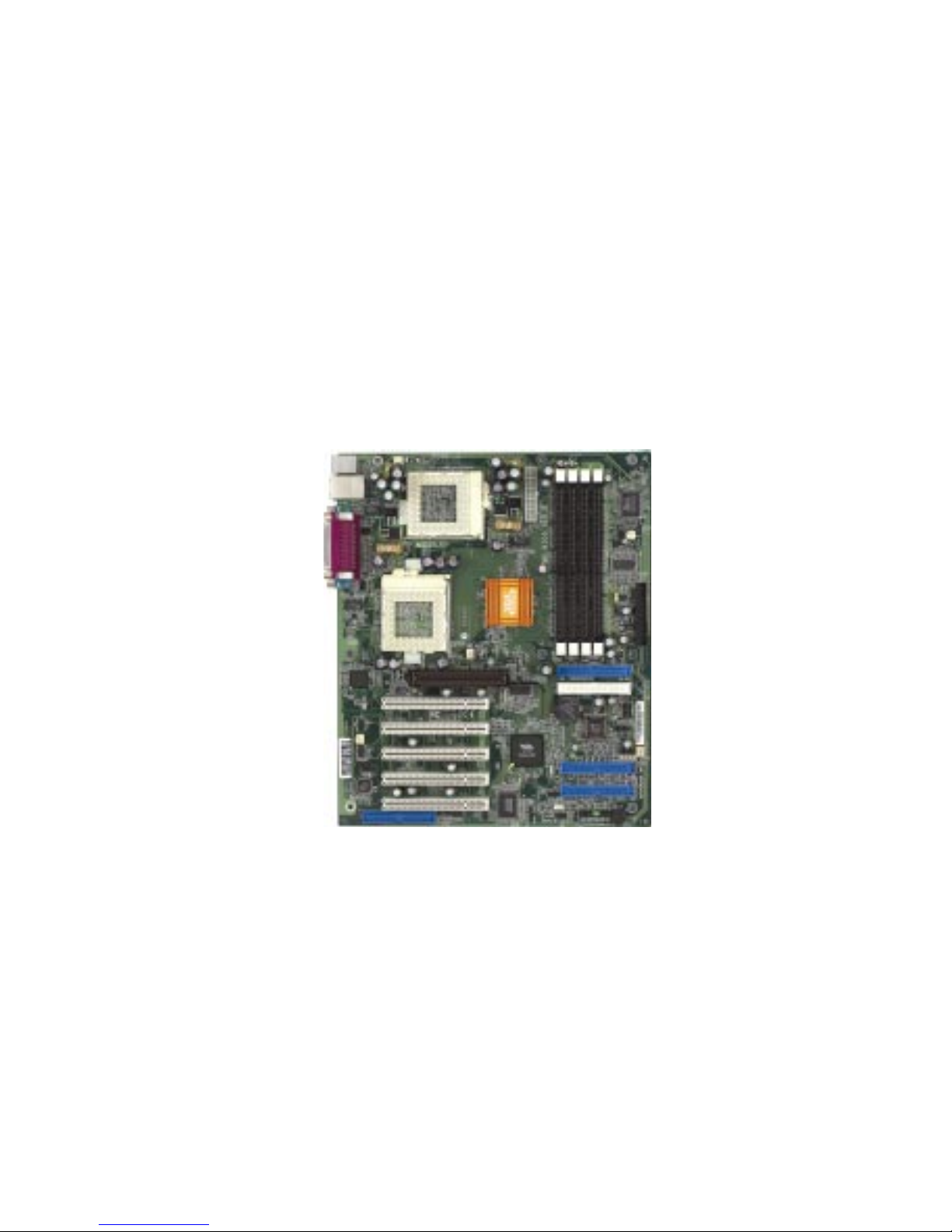
Thank you for purchasing the Pro266TD Master series (MS-9105)
ATX motherboard. Based on Apollo Pro266T (VT8653+VT8233) chipset,
the motherboard supports SINGLE/DUAL Intel® Pentium® III processors
(FC-PGA/FC-PGA2) and is designed for inexpensive workstation and entrylevel server markets.
There are two models for Pro266TD Master series: Pro266TD Master
and Pro266TD Master-LR. Pro266TD Master is the standard version. As
for Pro266TD Master-IR, it integrates both LAN and IDE RAID technology
on the board in addition to standard functions.
This chapter includes the following topics:
Mainboard Specification 1 -2
Mainboard Layout 1-4
Quick Components Guide 1 - 6
Key Features 1-7
MSI Special Features 1 -8
1
Chapter 1
1-2
CPU
z Supports Single/Dual Intel® Pentium® III processors
z Supports Coppermine up to 1.1GHz @ 133MHz FSB
z Supports Tualatin up to 1.26GHz or higher @ 133MHz FSB
Chipset
z VIA® VT8653 chipset (552 BGA)
- 100/133MHz FSB settings
- AGP 4x and PCI Advanced high performance memory controller
z VIA® VT8233 chipset (376 BGA)
- High Bandwidth Vlink Client controller
- Integrated Fast Ethernet LPC
- Ultra DMA 33/66/100 master mode PCI EIDE controller
- ACPI
z 266MB/sec high bandwidth North/South Bridge V-Link Bus
Clock Generator
z 100MHz/133MHz clocks are supported.
Main Memory
z Supports eight memory banks using four184-pin DDR DIMM
z Supports up to 4GB ECC registered DDR200/266 SDRAM
z Supports 2.5v DDR SDRAM
Slots
z One (Accelerated Graphics Port) AGP slot
- AGP specification compliant
- Supports AGP 2.0 4x
z Five 32-bit Master PCI Bus slots
z Supports 3.3v/5v PCI bus Interface
Mainboard Specification
Note: Both Tualatin with 256K L2 cache and Tualatin with
512K L2 cache are able to be used on the motherboard. But
Tualatin with 256K L2 cache can be used only when you
install SINGLE CPU on the board.

Introduction
1-3
On-Board IDE
z An IDE controller on the VIA® VT8233 chipset provides IDE HDD/CD-
ROM with PIO, Bus Master and Ultra DMA 33/66/100 operation modes.
z Can connect up to four IDE devices
Promise 20265R On-Board (Pro266TD Master-LR only)
z Supports IDE RAID 0, 1
z Can connect up to four IDE devices
On-Board Peripherals
z On-Board Peripherals include:
- 1 floppy port supports 2 FDDs with 360K, 720K, 1.2M, 1.44M and
2.88Mbytes.
- 2 serial ports (COMA + COM B)
- 1 parallel port supports SPP/EPP/ECP mode
- 6 USB 1.1 ports (2 Rear Connectors/ 4 from USB Front Pin Headers)
- 1 IrDA connector for SIR/CIR/ASKIR/HPSIR.
Network (Pro266TD Master-LR only)
z Intel 82559 Lan controller
- Integrated IEEE 802.3 10BASE-T and 100BASE-TX compatible PHY
- Wake-On-LAN and WFM 2.0 support
- ACPI and PCI Power Management
BIOS
z The mainboard BIOS provides “Plug & Play” BIOS which detects the
peripheral devices and expansion cards of the board automatically.
z The mainboard provides a Desktop Management Interface (DMI) func-
tion which records your mainboard specifications.
Dimension
z A TX Form Factor: 30.4cm x 25.4cm
Mounting
z 9 mounting holes, 6 Layers
Chapter 1
1-4
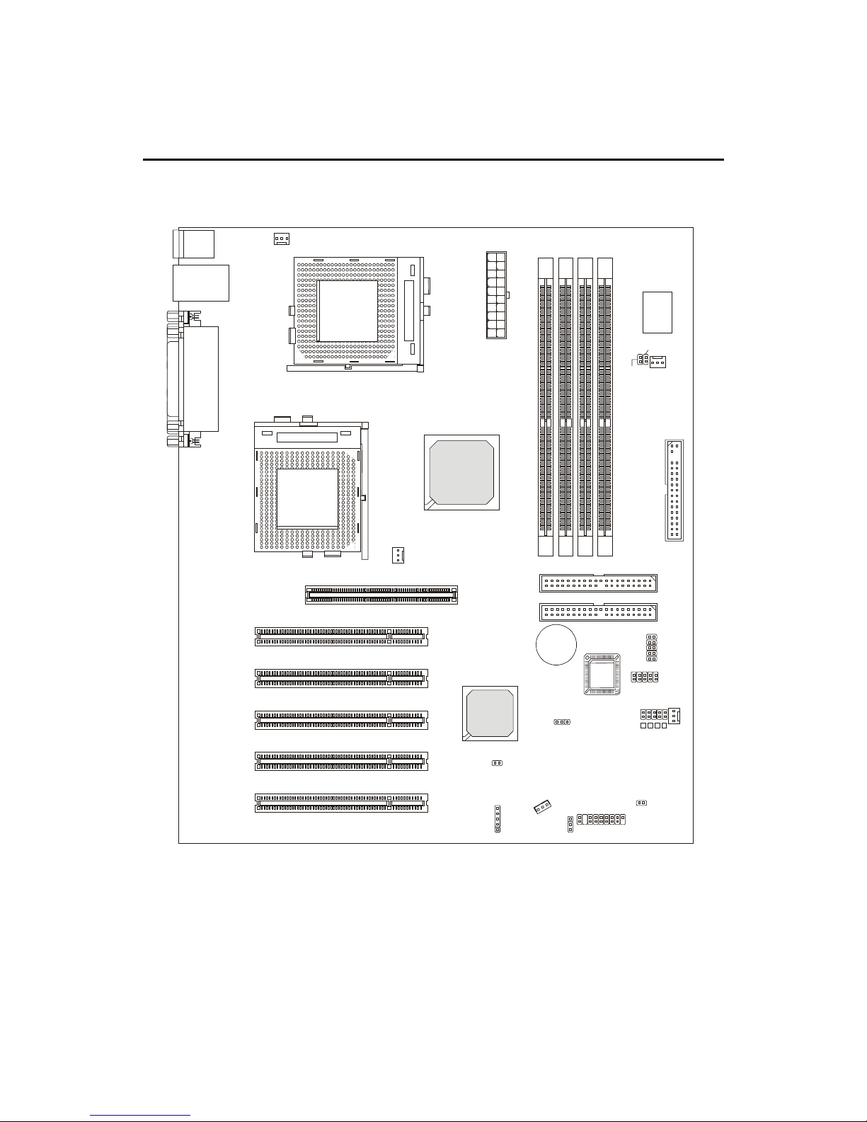
Mainboard Layout
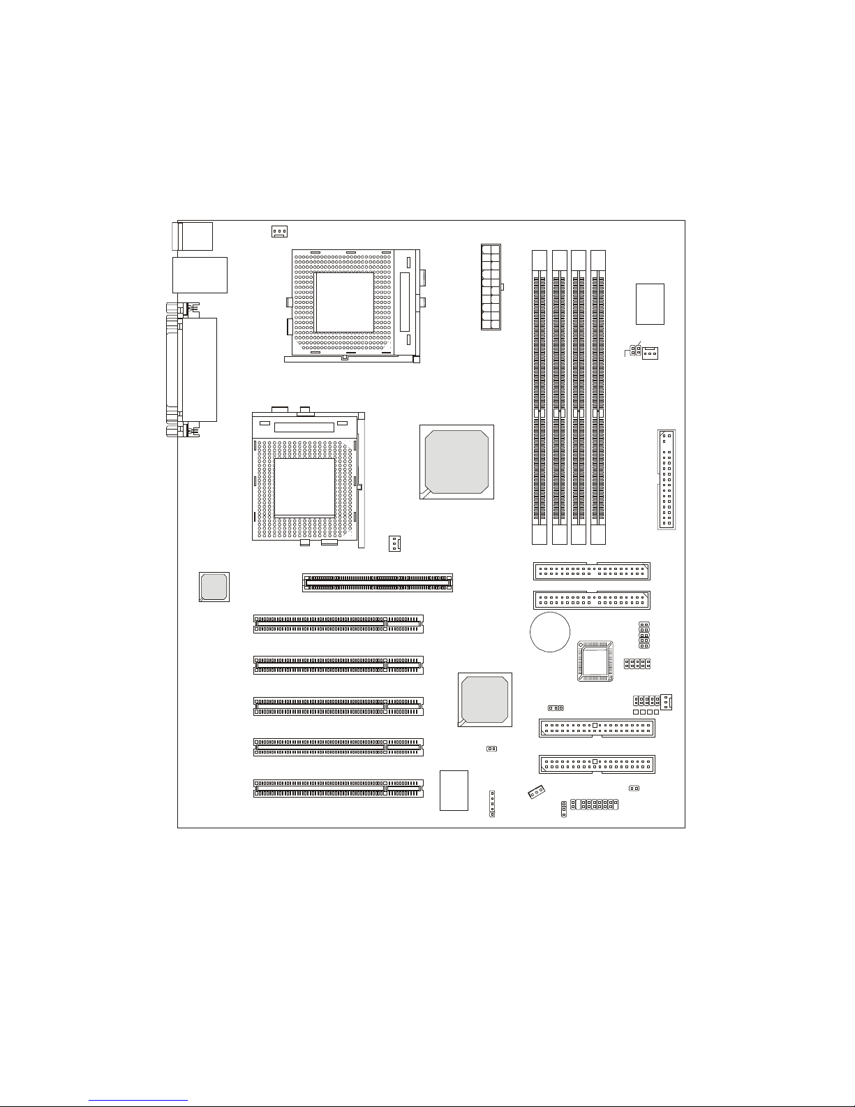
Pro266TD Master (MS-9105) A TX Mainboard
AGP Slot
BATT
+
VT82 33
VT8653
D
D
R
1
D
D
R
2
D
D
R
3
D
D
R
4
USB3
USB2
LED 2- 5
J14
JRMS1
JTECH1
JCASE1
A
T
X
P
o
w
e
r
S
u
p
p
l
y
JFP1
CPUFN2
CPUFN1
SYSFN1
S
Y
S
F
N
2
JGL1
JMDM1
JGS1
BIOS
PCI Slot 1
PCI Slot 2
PCI Slot 3
PCI Slot 4
PCI Slot 5
JBAT1
JWOL1
T op : Parallel Port
Bottom:
COM A
COM B
Top : mouse
Bottom: keyboard
USB ports
S
O
C
K
E
T
3
7
0
S
O
C
K
E
T
3
7
0
Winbond
W83627HF-AW
FDD 1
IDE 1
IDE 2
Introduction
1-5
Pro266TD Master-LR (MS-9105) A TX Mainboard
AGP Slot
BATT
+
Intel
Gd82559
VT82 33
VT8653
D
D
R
1
D
D
R
2
D
D
R
3
D
D
R
4
USB3
USB2
LED 2- 5
J14
JRMS1
JTECH1
JCASE1
A
T
X
P
o
w
e
r
S
u
p
p
l
y
JFP1
CPUFN2
CPUFN1
SYSFN1
S
Y
S
F
N
2
JGL1
JMDM1
JGS1
BIOS
PCI Slot 1
PCI Slot 2
PCI Slot 3
PCI Slot 4
PCI Slot 5
JBAT1
JWOL1
T op : Parallel Port
Bottom:
COM A
COM B
Top : mouse
Bottom: keyboard
Top: LAN Jack
Bottom: USB ports
S
O
C
K
E
T
3
7
0
S
O
C
K
E
T
3
7
0
Winbond
W83627HF-AW
PROMISE
PDC20265R
FDD 1
IDE 1
IDE 2
IDE 3
IDE 4

Chapter 1
1-6
Quick Components Guide
Component Function Reference
DIMM1~4 Installing DDR DIMM modules See p. 2-5~2-6
Socket 370 Installing Single/Dual CPUs See p. 2-2~2-4
CPUFN1/2 Connecting to CPU FAN See p. 2-20
SYSFN1/2 Connect ing to SYSTEM FAN See p. 2-20
ATX Power Supply Installing power supply See p. 2-7
IDE1& IDE2 Connecting to IDE hard disk drives See p. 2-13
IDE3& IDE4 Connecting to IDE RAID hard disk drives See p. 2-14
FDD1 Connecting to floppy disk drive See p. 2-12
USB2/3 Connecting to USB interfaces See p. 2-22
PCI Slot 1~5 Installing PCI expansion cards See p. 2-25
AGP Slot Installing AGP cards See p. 2-25
JMDM1 Connecting to modem module See p. 2-19
JWOL1 Connecting to LAN module See p. 2-23
JBAT1 Clearing CMOS data See p. 2-24
JFP1 Connecting to case See p. 2-15
JGS1 Connecting to power saving switch See p. 2-18
JGL1 Connecting to power saving LED See p. 2-17
J14 Connecting to IR modules See p. 2-19
JCASE1 Connecting to chassis intrusion switch See p. 2-18
JRMS1 Connecting to power switch See p. 2-21
JTECH1 Connecting to 20cm thermistor See p. 2-21

Introduction
1-7
z ATX Form Factor
z CPU: Socket 370 for Single/Dual Intel
®
Pentium® III (FC-PGA/FC-PGA2)
Processors
z Memory: 4 DDR DIMMs
z Slot: 1 AGP slot, 5 PCI slots
z I/O: 2 serial ports, 1 parallel port, 6 USB 1.1 ports, 1 floppy port, 1 IrDA
connector, 2 IDE RAID connectors (Pro266TD Master-LR only), 1 LAN
jack (Pro266TD Master-LR only)
z D-LED™ -- 4 Diagnostics LEDs embedded on the mainboard
z LAN Wake up Function
z Modem (External/Internal) Ring Wake up Function
z Promise 20265R Onboard with support for IDE RAID 0, 1 (Pro266TD
Master-LR only)
Key Features
Chapter 1
1-8
MSI Special Features
The MSI special features are designed by MSI R&D which are only available in
MSI mainboards. The mainboard is equipped with D-LED™.
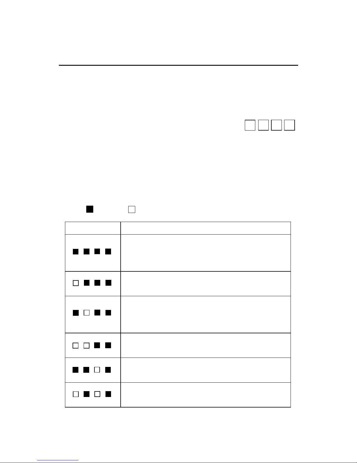
D-LED™
The D-LED™ uses graphic signal display to help
users understand their system. Four LEDs embedded on
the mainboard provide up to 16 combinations of signals
to debug the system. The 4 LEDs can debug all problems
that fail the system, such as VGA, RAM or other failures. This special
feature is very useful for the overclocking users. These users can use the
feature to detect if there are any problems or failures. The definitions of LED
signal combinations are listed below:
Diagnostic LED
2
3
4 5
D-LED Description
System Power ON
- The D-LED will hang here if the processor is damaged or not installed
properly.
Early Chipset Initialization
Memory Detection Test
- Testing onboard memory size. The D-LED will hang if the memory
module is damaged or not installed properly.
Decompressing BIOS image to RAM for fast booting.
Initializing Keyboard Controller.
Testing VGA BIOS
- This will start writing VGA sign-on message to the screen.
Red
Green
2345
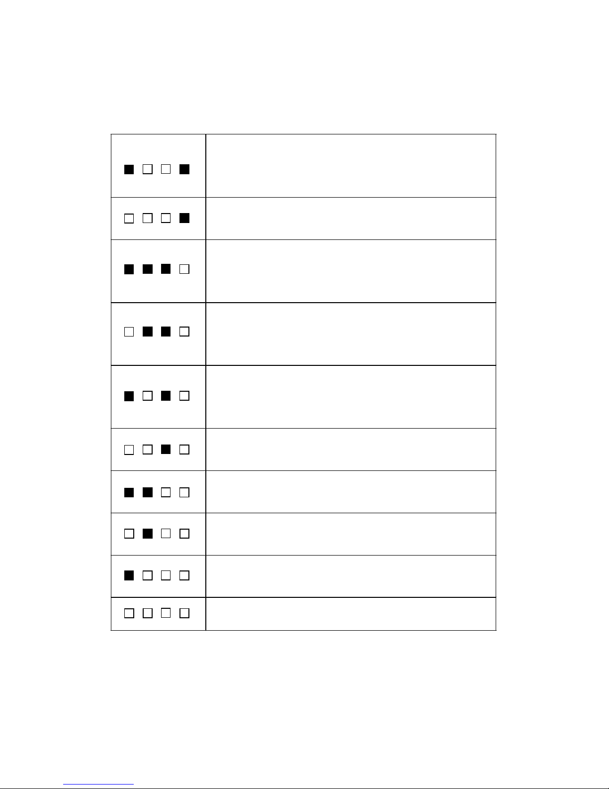
Introduction
1-9
Processor Initialization
- This will show information regarding the processor (like brand name,
system bus, etc…)
Testing RTC (Real Time Clock)
Initializing Video Interface
- This will start detecting CPU clock, checking type of video onboard.
Then, detect and initialize the video adapter.
BIOS Sign On
- This will start showing information about logo, processor brand name,
etc….
Testing Base and Extended Memory
- Testing base memory from 240K to 640K and extended memory
above 1MB using various patterns.
Assign Resources to all ISA.
Initializing Hard Drive Controller
- This will initialize IDE drive and controller.
Initializing Floppy Drive Controller
- This will initializing Floppy Drive and controller.
Boot Attempt
- This will set low stack and boot via INT 19h.
Operating System Booting

Hardware Setup
2-1
Hardware Setup
This chapter provides you with the information about hardware setup
procedures. While doing the installation, be careful in holding the components and follow the installation procedures. For some components, if you
install in the wrong orientation, the components will not work properly.
Use a grounded wrist strap before handling computer components.
Static electricity may damage the components.
This chapter contains the following topics:
Central Processing Unit (CPU) 2- 2
Memory 2 -5
Power Supply 2 - 7
Back Panel 2 -8
Connectors 2-12
Jumpers 2-24
Slots 2-25
2
Chapter 2. Hardware Setup
Chapter 2
2-2
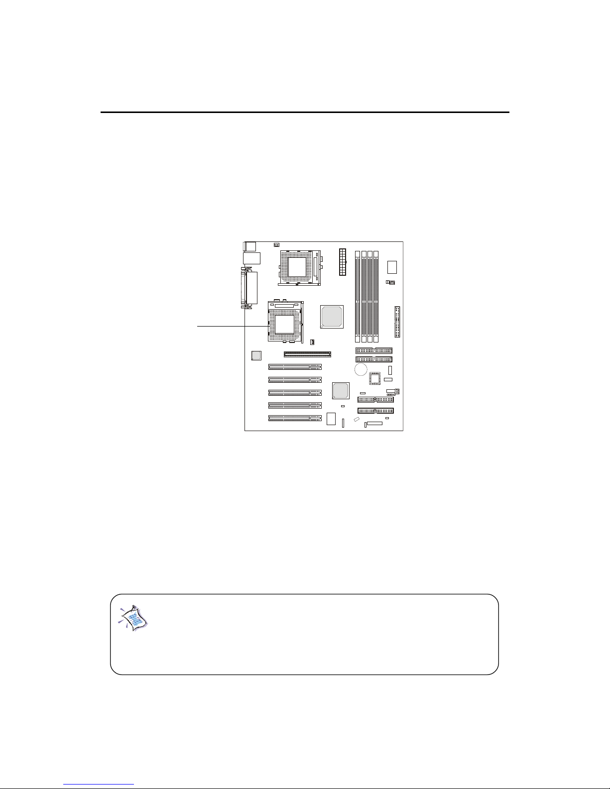
Central Processing Unit: CPU
The mainboard supports Single/Dual Intel® Pentium III processors.
The mainboard uses two CPU sockets called Socket 370 for easy CPU
installation. You can install SINGLE or DUAL CPUs on the board to meet
your own needs. Keep the following points in mind before installing CPU(s):
z If SINGLE CPU is intended, always install the CPU on the CPU1
socket.
z T o install DUAL CPUs on the board, you must use the same type
of CPUs running at the same FSB frequency.
When you are installing the CPU, make sure the CPU has a Heat
Sink and a cooling fan attached on the top to prevent overheating. If you do
not find the Heat Sink and cooling fan, contact your dealer to purchase and
install them before turning on the computer.
CPU1
Note: Both Tualatin with 256K L2 cache and Tualatin with
512K L2 cache are able to be used on the motherboard. But
Tualatin with 256K L2 cache can be used only when you
install SINGLE CPU on the board.
Hardware Setup
2-3
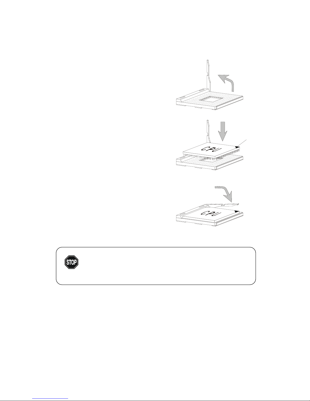
1.
Pull the lever sideways away
from the socket. Then, raise
the lever up to a 90-degree
angle.
CPU Installation Procedures
2. Look for the gold arrow.
The gold arrow should point
towards the end of lever.
The CPU will only fit in the
correct orientation.
3. Hold the CPU down firmly,
and then close the lever to
complete the installation.
Open Lever
Gold Arrow
Sliding
Plate
Close
Lever
Overheating will seriously damage the CPU
and system, always make sure the cooling fan can work
properly to protect the CPU from overheating.
WARNING!

Chapter 2
2-4
CPU Core Speed Derivation Procedure
If CPU Clock = 100MHz
Core/Bus ratio = 7
then CPU core speed = Host Clock x Core/Bus ratio
= 100MHz x 7
= 700MHz
Overclocking
This motherboard is designed to support overclocking.
However, please make sure your components are able to
tolerate such abnormal setting, while doing overclocking.
Any attempt to operate beyond product specifications is
not recommended. We do not guarantee the damages or
risks caused by inadequate operation or beyond product
specifications.
WARNING!

Hardware Setup
2-5
The mainboard provides 4 sockets for 184-pin DDR DIMM (Double In-
Line Memory Module) modules and supports a maximum memory size of 4GB.
Memory
DDR DIMM Slots
(DIMM 1~4)
Introduction to DDR SDRAM
You can install PC1600/PC2100 DDR SDRAM modules on the DDR
DIMM slots (DIMM 1~4).
DDR (Double Data Rate) SDRAM is similar to conventional SDRAM,
but doubles the rate by transfering data twice per cycle. It transfers data on
both the rising and falling edges of the clock. Conventional SDRAM only
uses the rising edge of the clock to transfer data. Therefore, conventional
SDRAM is called SDR (Single Data Rate) SDRAM.
DDR SDRAM uses 2.5 volts as opposed to 3.3 volts used in SDR
SDRAM, and requires 184-pin DIMM modules rather than 168-pin DIMM
modules used by SDR SDRAM. DDR SDRAM is also known as SDRAM-II,
DDR DRAM and DSDRAM (Double-Speed DRAM).
T wo types of DDR are available at the time of writing: PC1600 & PC2100.
PC1600 DDR SDRAM running at 100MHz will produce about 1.6GB/s memory
bandwidth. PC2100 running at 133MHz will produce 2.1GB/s memory
bandwidth. High memory bandwidth makes DDR an ideal solution for high
performance PC, workstations and servers.
Chapter 2
2-6
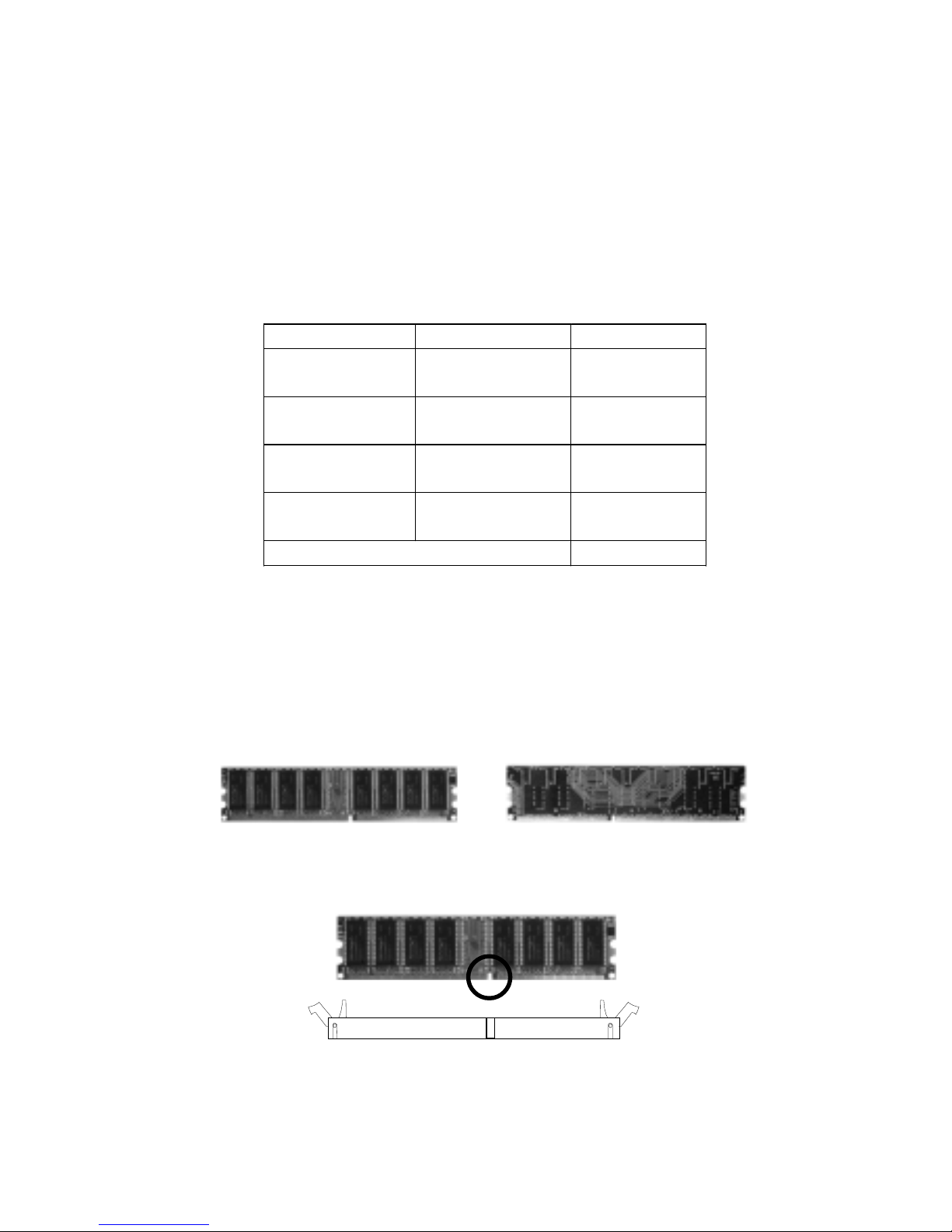
DIMM Modules Combination
At least one DIMM module should be installed on the motherboard.
Memory modules can be installed on the slots in any order. The single-/
double-sided memory modules that each DIMM slot supports are listed as
below:
S: Single Side D: Double Side
Socket Memory Module Total Memory
DIMM 1
(Bank0 & Bank1)
S/D 64MB ~ 1GB
DIMM 2
(Bank2 & Bank3)
S/D 64MB ~ 1GB
DIMM 3
(Bank4 & Bank5)
S/D 64MB ~ 1GB
DIMM 4
(Bank6 & Bank7)
S/D 64MB ~ 1GB
Maximum System Memory Supported 64MB ~ 4GB
1. The DDR DIMM has only one notch on the center of module. The
module will only fit in the right orientation.
2. Insert the DIMM memory module vertically into the DIMM slot.
Then push it in.
3. The plastic clip at each side of the DIMM slot will automatically
close.
Volt
Front Side
Rear Side
Installing DIMM Modules
Hardware Setup
2-7
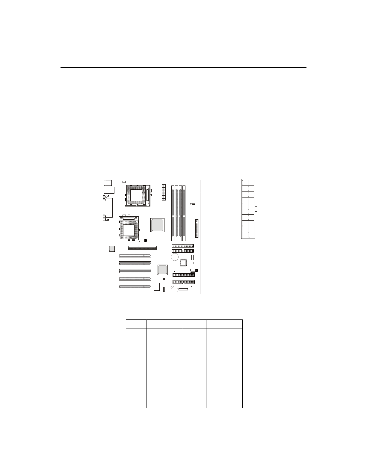
Power Supply
A TX 20-Pin Power Supply
This connector allows you to connect to an ATX power supply. To
connect to the ATX power supply, make sure the plug of the power supply is
inserted in the proper orientation and the pins are aligned. Then push down
the power supply firmly into the connector.
ATX
Power Connector
The mainboard supports ATX power supply for the power system.
Before inserting the power supply connector, always make sure that all components are installed properly to ensure that no damage will be caused.
10
1
20
11
PIN SIGNAL
11 3.3V
12 -12V
13 GND
14 PS_ON
15 GND
16 GND
17 GND
18 -5V
19 5 V
20 5 V
PIN SIGNAL
1 3.3V
2 3.3V
3 GND
45V
5 GND
65V
7 GND
8 PW_OK
9 5V_SB
10 12V
Chapter 2
2-8
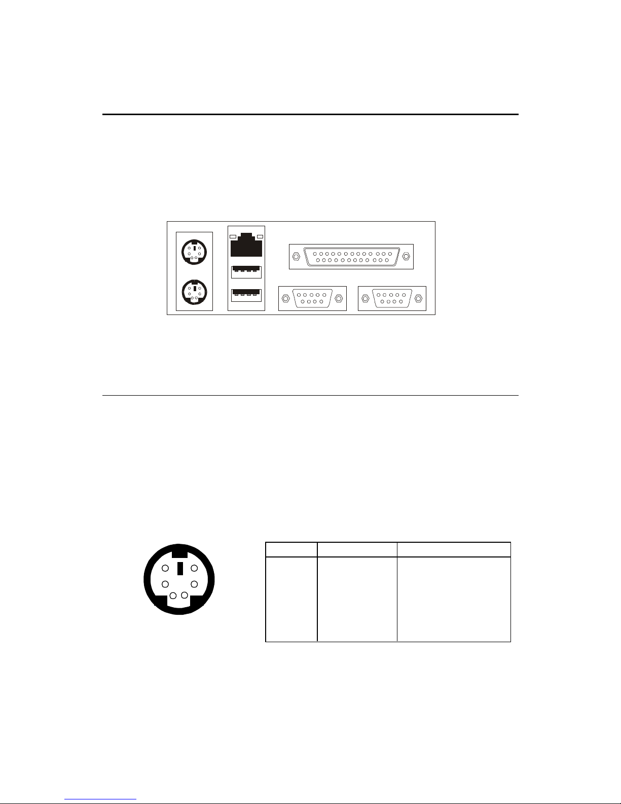
The Back Panel provides the following connectors:
Mouse
Keyboard
USB
Parallel
COM A COM B
Mouse Connector
The mainboard provides a standard PS/2® mouse mini DIN connector
for attaching a PS/2® mouse. You can plug a PS/2® mouse directly into this
connector.
Back Panel
PS/2 Mouse (6-pin Female)
2
1
3
4
5
6
PIN SIGNAL DESCRIPTION
1 Mouse DATA Mouse DATA
2 NC No connection
3 GND Ground
4 VCC +5V
5 Mouse Clock Mouse clock
6 NC No connection
Pin Definition
LAN
(Pro266TD Master-LR only)
Hardware Setup
2-9
Keyboard Connector
The mainboard provides a standard PS/2® keyboard mini DIN connector for attaching a PS/2® keyboard. You can plug a PS/2® keyboard directly into
this connector.
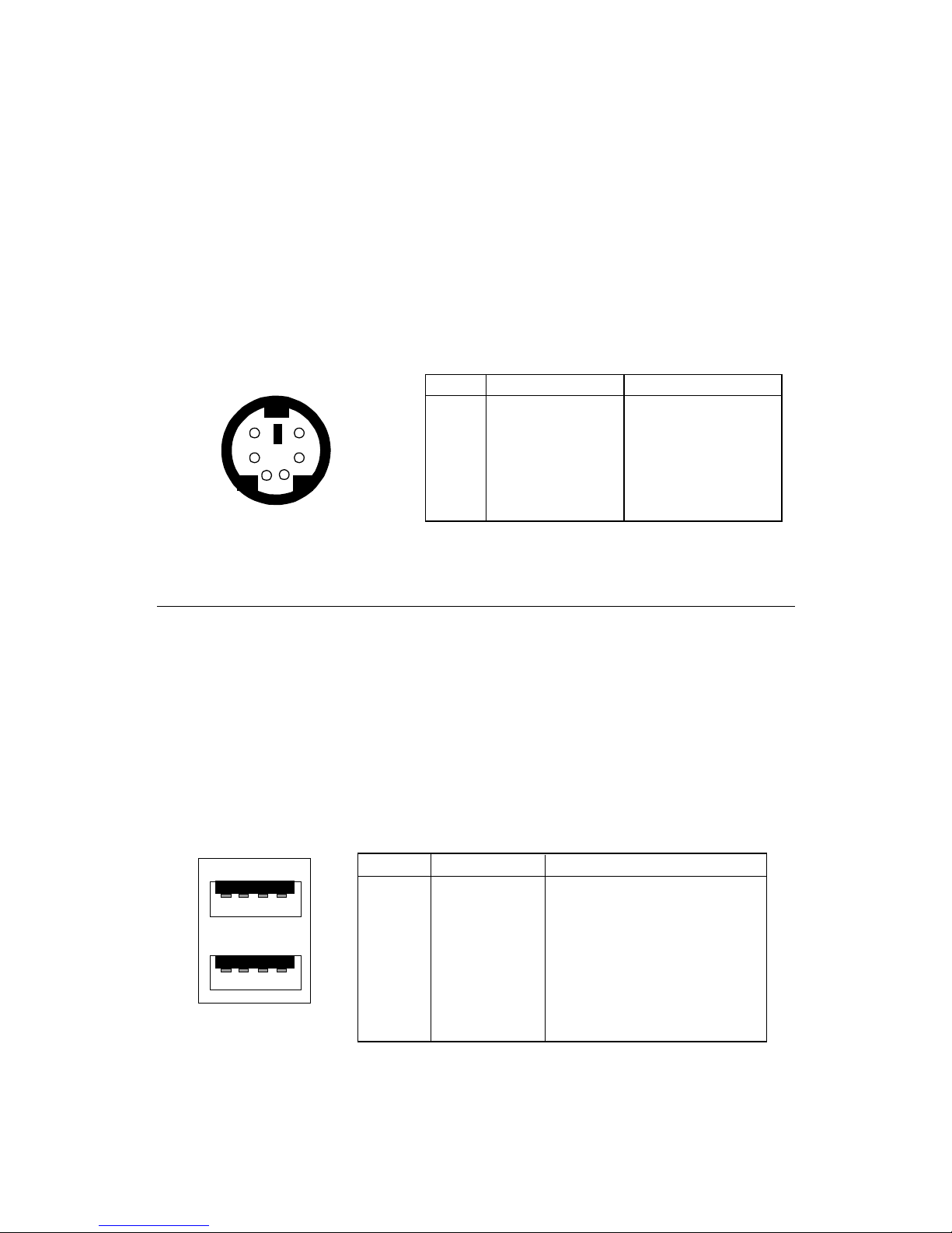
USB Connectors
The mainboard provides a UHCI (Universal Host Controller Interface)
Universal Serial Bus root for attaching USB devices such as keyboard, mouse
or other USB-compatible devices. You can plug the USB device directly into
ths connector.
21
34
5
6
PS/2 Keyboard (6-pin Female)
PIN SIGNAL DESCRIPTION
1 Keyboard DATA Keyboard DATA
2 NC No connection
3 GND Ground
4 VCC +5V
5 Keyboard Clock Keyboard clock
6 NC No connection
Pin Definition
USB Ports
1 2 3 4
5 6 7 8
PIN SIGNAL DESCRIPTION
1 VCC +5V
2 -Data 0 Negative Data Channel 0
3 +Data0 Positive Data Channel 0
4 GND Ground
5 VCC +5V
6 -Data 1 Negative Data Channel 1
7 +Data 1 Positive Data Channel 1
8 GND Ground
USB Port Description
 Loading...