

Page 1

MSI-8000
RF Remote Display
Operator’s Manual
133063 Rev C
Page 2

Page 3

Contents
1.0 Introduction ............................................................................1
1.1 Safety Section ....................................................................... 2
1.2 Key Descriptions ................................................................. 4
1.2.1 MSI-8000 Annunciators .............................................................5
1.3 Specifications ....................................................................... 6
1.4 Features ................................................................................ 7
1.5 FCC Statement ..................................................................... 7
1.6 International RF Certs .......................................................... 7
1.7 Getting Started ..................................................................... 8
1.8 Options .................................................................................. 8
1.9 Unpacking ............................................................................. 8
1.10 Battery Charging ................................................................... 9
1.11 Charger LED Modes ............................................................. 9
1.12 Battery Longevity ................................................................. 9
2.0 Operation ..............................................................................10
2.1 Power .................................................................................. 10
2.2 Zero ..................................................................................... 10
2.3 Tare ..................................................................................... 10
3.0 User Defined Function Keys .................................................12
4.0 Set Up ...................................................................................16
4.1 Menu Map ........................................................................... 16
4.2 Function Keys ..................................................................... 17
4.3 Auto-Off ............................................................................... 18
5.0 COMM Set Up .......................................................................19
5.1 RF Setup ............................................................................. 21
5.2 RF Set Up, Dyna-Link And MSI Crane Scales ................... 23
5.3 MSI8000 With Multiple Sensors ......................................... 23
5.4 Summing Modes ................................................................. 24
5.4.1 Modes .....................................................................................24
5.5 Behavior Of Zero And Tare In Multiple Channel Systems 25
5.6 Printer Set Up ..................................................................... 25
5.7 Control Modes .................................................................... 26
5.8 Standard Print Strings ........................................................ 26
5.9 COMM Port Hardware ........................................................ 28
5.10 Service Counters ................................................................ 29
Technical training seminars are available through Rice Lake Weighing Systems.
Course descriptions and dates can be viewed at www.ricelake.com/training
or obtained by calling 715-234-9171 and asking for the training department.
© Rice Lake Weighing Systems. All rights reserved. Printed in the United States of America.
Specifications subject to change without notice.
Rice Lake Weighing Systems is an ISO 9001 registered company.
December 2, 2013
Page 4

ii MSI8000 Operator’s Manual
6.0 Appendix ..............................................................................31
6.1 Troubleshooting .................................................................. 31
6.2 Error Codes ......................................................................... 34
6.3 Mechanical Dimensions ..................................................... 35
6.4 Firmware Update Procedure .............................................. 36
The MSI Limited Warranty ............................................................38
Rice Lake continually offers web-based video training on a growing selection
of product-related topics at no cost. Visit www.ricelake.com/webinars.
Page 5

Introduction 1
1.0 Introduction
The MSI-8000 RF Remote Display is a wireless remote display for viewing weight from
several compatible MSI Crane Scales and Dyna-Links. It is fully sealed for outdoor use in
most ambient conditions. Using a Remote Display enhances the safety and usability of the
MSI’s Dyna-Link and Crane Scale systems. The RF Remote Indicator allows tension
monitoring from a distance and adds the ability to print and store data. The MSI-8000 uses
a rechargeable Lithium Polymer battery providing up to 36 hours (typical) of continuous
use between charges.
If you have any questions or comments please contact
Measurement Systems International:
Phone (toll free): 1-800-874-4320
Authorized distributors and their employees can view or download this manual
from the Measurement Systems International distributor site at:
www.msiscales.com.
Page 6
2 MSI-8000 Operator’s Manual
1.1 Safety Section
Safety Symbol Definitions:
Important
WARNING
Indicates a potentially hazardous situation that, if not avoided could
result in death or serious injury, and includes hazards that are exposed
when guards are removed.
Indicates information about procedures that, if not observed, could
result in damage to equipment or corruption to
and loss of data.
General Safety
WARNING
Do not operate or work on this equipment unless you have read and
understand the instructions and warnings in the this Manual. Contact
any Measurement Systems International dealer for replacement
manuals. Proper care is your responsibility.
Failure to heed may result in serious injury of death.
DO NOT allow minors (children) or inexperienced persons to operate this unit.
DO NOT stand near the load being lifted as it is a potential
falling hazard. Keep a safe
distance.
DO NOT use for purposes other then weigh
t taking or dynamic load monitoring.
DO NOT use any load bearing component that is worn beyond 5% of the original
dimension.
DO NOT use any associated lifting product if any of the components of the load t
rain
are cracked, deformed, or show signs of fatigue.
DO NOT exceed the rated load limit of the associated Scale/Dynamometer unit,
riggi
ng elements, or the lifting structure.
DO NOT allow multi-point contact with the hook, shackle, or lifting eye of the
associated Scale/Dynamometer unit.
DO NOT allow high torque on the Scale/Dynamometer
unless it is specifically designed
for high torque.
DO NOT make alterations or modifications t
o the unit or associated load bearing
devices.
DO NOT remove or obscure warning labels.
For guidelines on the safe rigging and loadi
ng of overhead scales and dynamometers,
read the "MSI Crane Scale Safety and Periodic Maintenance Manual" (available at
www.msiscales.com).
Keep hands, feet and loose clothing
away from moving parts.
There are no user serviceable parts within the MSI-8000. Any repairs are to be
p
erformed by qualified service personnel only.
Page 7
Introduction 3
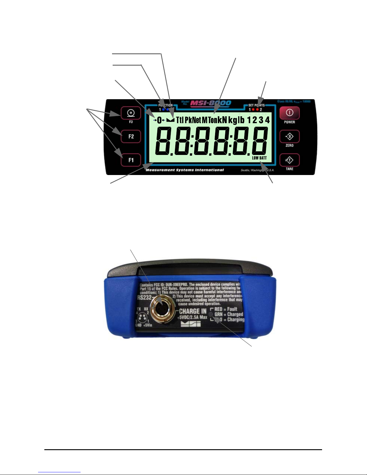
Battery Low
Stable Indicator
Center of Zero
Function Key LEDs
User Programmable
Function Keys
Units & Tension
Mode Annunciators
Set Point
Alarm LEDs
6 Digit 1 in (26 mm)
Sunlight visible LCD
Tension Display
Figure 1-1. MSI-8000 Front Panel
Charger Port/RS-232 I/O
Charge Status LED
Figure 1-2. MSI-8000 Side Panel, Charging and RS-232 Port
Page 8
4 MSI-8000 Operator’s Manual
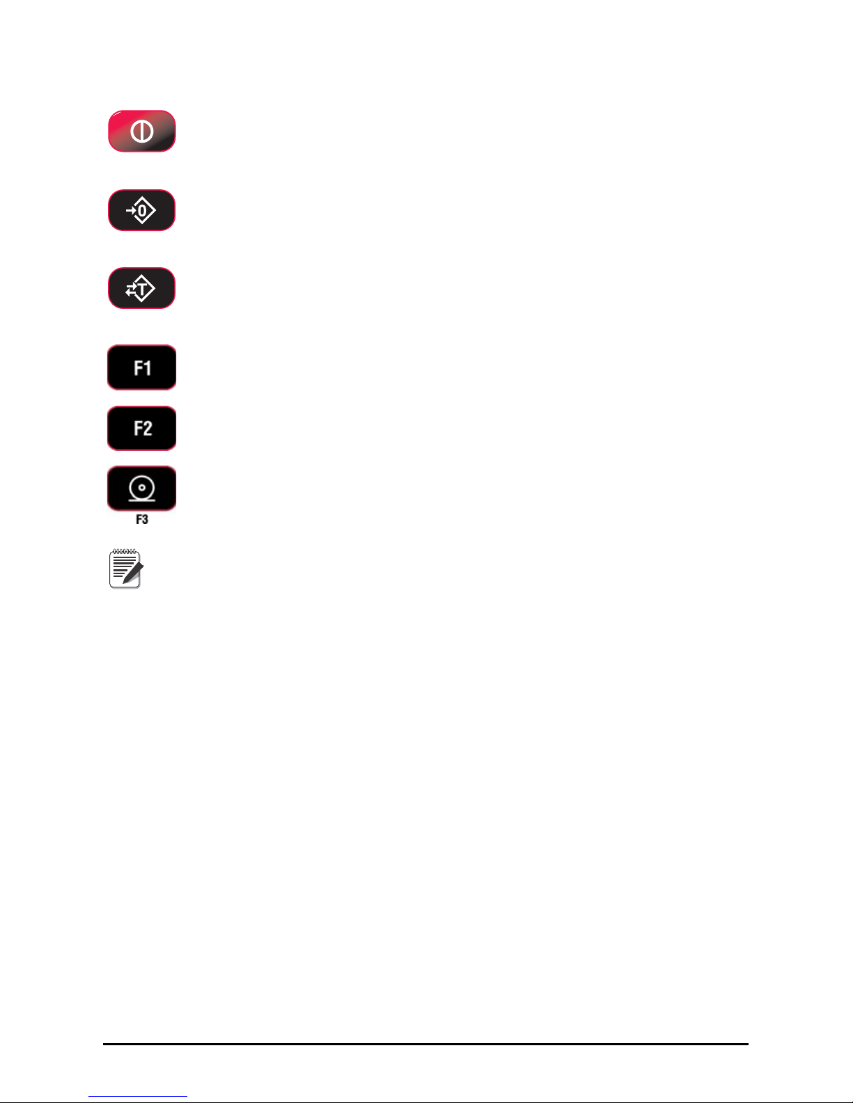
1.2 Key Descriptions
POWER
Tur ns the MSI-8000 ON and OFF.
When in setup mode, returns to the normal weight/tension display
without
storing the changes.
ZERO
Used to zero out residual tension on the link.
When in the setup mode, drops back one menu level.
At the root menu level, stores the changes and returns to tension mode.
TARE
Removes the current load and puts the system in to the NET weight mode.
Programmable to user selectable functions, see Section 3.0.
Default – Peak Hold.
Functions as the ENTER/SELECT key when in setup menus
Programmable to user selectable functions, see Section 3.0.
Default – Display & Function Test
Functions as the scroll
key in setup menus
PRINT Key - Defaulted to the Print function.
Note
If the text is discussing a function key, the function key will be displayed
as Fx-YYYYY with the programmed User Key function in italics. F1 and F2
can both be programmed to all available user functions.
If a function key does not work, it is probably because the connected Scal
e/Dyna-Link
is not setup to support the key. For example, if the Function key is set for TOTAL, you
must also setup the TOTAL mode in the Setup Menu of the target scale.
Page 9
Introduction 5
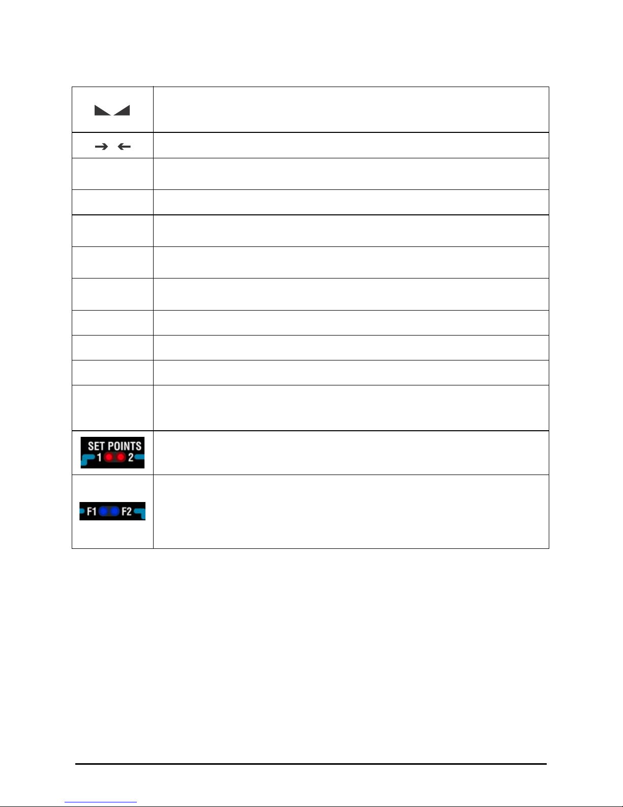
1.2.1 MSI-8000 Annunciators
The MSI-8000 uses LCD annunciators to indicate tension mode and other information.
Table 1-1. MS I-8000 Annunciators
The stable annunciator indicates that the tension force has settled within the
motion window (usually ±1d).
When this symbol is off, the Scale / Dyna-L
ink will not zero, tare, or totalize.
Center-of-Zero- Indicates the tension is within 1/4d of zero.
BT
LOW BATTERY- Appears when approximately 10% of battery life remains.
The BT symbol blinks when automatic shutdown is eminent.
Pk
PEAK- Indicates the RF Linked Device is in the Peak Hold mode.
Ttl
TOTAL – Indicates the RF Linked Device is displaying the Total accumulated
weight. This is a temporary display lasting less than 5 seconds.
Net
NET – Indicates the RF Linked Device is in the Net tension mode. A Tare weight
is subtracted from the gross tension.
M
M – In conjunction with the Ton annunciator, indicates the RF Linked Device is
displaying Metric Tons.
kg
kg – Indicates tension display is in kilograms.
kN
kN – Indicates tension display is in kiloNewtons.
lb
lb – Indicates tension display is in pounds.
Ton
Ton – Illuminated alone, indicates the RF Linked Device is displaying in US Short
Tons (1 ton = 2000 lb.). When illuminated along with the ‘M’ the RF Linked
Device is displaying in Metric Tons (1 metric ton = 1000 kg)
SET POINTS – User programmable set points for overload warnings. Set Points
1 and 2 are high brightness Red LEDs
F1 F2 – These Blue LEDs are used to indicate various operational features of
functions programmed into the F1 and F2 keys.
Example:
In Peak Hold mode the associated LED wi
ll blink whenever a new peak reading
is captured.
0
Page 10

6 MSI-8000 Operator’s Manual
1.3 Specifications
Table 1-2. Specifi cati ons
Accuracy
Power
Display
Operating Temp
Operating Time
Enclosure
F1, F2, and F3
Calibration
Auto-Off Mode
Units
Totalization
Set Points
Weight accuracy is dependent on the li
nked Tension unit, a Dyna-Link or
MSI Crane scale. Refer to the appropriate User Guide for accuracy
specifications. The MSI-8000 mirrors the display of the connected
device.
Battery operated by a custom Li
thium Polymer cell. Not user
replaceable. Estimated number of charges is >300. Life is prolonged
with frequent recharging and not allowing the deep discharging of the
battery.
6 large, 1 in (26 mm) numeric digits
- 40°F to +122°F (-40°C to +50°C), Rated accuracy range -10°C to
+40°C.
>24 hours typical.
NEMA 4/IP65 with charger port plug installed.
Programmable multifunction buttons for use as TEST, TOTAL, Total
Remot
e Devices, PEAK, TARE, NET/GROSS, VIEW TOTAL, PRINT and
High Res mode
No Calibration parameters are stored in the
MSI-8000. However, it can
be used to calibrate an RF connected scale
Prolongs battery life by turning the power off after 15, 30, 45, or 60
min
utes (operator determined) of no weight activity
kg, lb., Tons (US short ton), Metric Tons, kiloNewtons (other Units
available with custom calibrations). Available units are determined by the
RF Linked Scale/Dyna-Link
Standard: Press button or Automatic; TOTAL weight up to 999999 X
100
0 units
Two internal Set Points with open drain ou
tputs, and two ultrabright
LEDs on indicator panel.
Page 11

Introduction 7
1.4 Features
• Designed to meet or exceed all US and International safety and environmental
standards.
• Reliable and easy to use wireless remote display
• No License required. Meets US and International RF Transmission Laws.
• Greater than 24 hours operation.
• Automatic Power Off conserves battery life by sensing no activity after 15, 30, 45 or
60 minutes, determined by operator, and turns Power off.
• Rugged construction throughout. IP65 / NEMA 4 for outdoor use. Shock cushioning
on the corners.
• Six large, 1 in (26 mm) LCD digits for clear tension readings.
• Selectable for kg / lb. / Tons (US Short) / Metric Tons / kiloNewtons.
• Automatic or manual weight totalization for loading operations.
• Two Set Points can be set for any in-range tension / weight value for operator alerts or
process control.
• ScaleCore Technology providing quick and easy firmware updates and calibration /
setup backup.
• Optional Hard-wired link for applications where RF is not allowed.
1.5 FCC Statement
Contains FCC ID: OUR-XBEEPRO
The MSI-8000 complies with Part 15 of the FCC Rules. Operation is subject to the
following conditions:
i This device may not cause harmful interference.
ii This device must accept any interference received, including interference that may
cause undesired operation.
1.6 International RF Certs
Canada Radio Cert. No.: IC: 4214A-XBEEPRO
Australia & New Zealand: AS4268:3000
Japan: Certificate of Radio Equipment in Japan No.: 08215111/AA/02
Europe and much of Asia:
The product is compliant with the following standards and/or other normative documents:
Safety (article 3.1A) EN60950-1:2001
EMC (article 3.1b) ETSI EN 301 489-1 v1.7.1 (2007-04) In accordance with the specific
requirements of ETSI EN 301 489-17 v1.2.1 (2002-08)
Spectrum (article 3.2) ETSI EN 300 328 v1.7.1 (2006-10)
Page 12

8 MSI-8000 Operator’s Manual
1.7 Getting Started
The MSI-8000 is usually shipped along with a compatible sensor unit such as an MSI-7300
Dyna-Link 2, or one of MSI’s advanced Crane Scales. MSI always ships these systems
pre-configured. If the MSI-8000 is purchased separately, or is to be used with a different
system, then the RF Transceivers will have to be mated. Follow the RF Setup Procedure in
Section 5.1.
Fully charge the battery by plugging the charger into the Charge Port. Depending on the
dischar
ge level of the battery this can take up to 6 hours.
Once the RF Setup is complete for the MSI-8000, the sy
stem will instantly connect with
the Scale / Dyna-Link. It is advised to do a site survey to identify operating range and
usability of the RF Link. The easiest way to accomplish this is to position the Scale /
Dyna-Link at an average operational height, and then try the link at various positions and
distances. Range may vary by the rotation of the Scale / Dyna-Link. The RF Transceivers
used in the MSI-8000 are capable of much further range than the 100’ typical spec, but
range is dependent on site and installation variables.
1.8 Options
Available options for your MSI-8000 include the following:
• Serial I/O cable (RS-232) MSI PN 503489-000
1 DCE Configuration, 503489-0002
DTE Configuration
• Serial I/O cable (RS-232) with charger pigtail MSI PN 503490-0001 DCE, 503489000
2 DTE
Note
Allows serial output while being powered with Charger.
• Serial I/O cable (RS-232), 4m TPU Jacket, un-terminated. MSI PN 14359
• 26’ (8m) Hardwired cable for RF free Remote D
isplay. Connects 8000 to 7300 Dyna-
Link. MSI PN 14052
• RF Remote Modem, RS-232, PN 14401, for direct connection to Computers,
S
coreboards, or serial printers.
• RF Remote Modem, RS-485, PN 14402, for direct connection to 485 Serial Devices.
• RF Remote Modem, USB, PN 14403, for direct connection to Computers USB ports.
• RF Remote Gateway for direct connection to an Ethernet LAN, PN 14404. For use
with MSI’
s SCCMP program.
• RF or Hardwired Scoreboard Display. Various digit sizes from 1.2” to 8”. Contact
MSI
for models available.
1.9 Unpacking
When unpacking the MSI-8000, ensure that all parts are accounted for. Check the MSI8000 for any visible damage and immediately report any damage to your shipper. It is
advisable to use the original shipping container when shipping or transporting the
MSI-8000. A
standard MSI-8000 is shipped with a battery charger. The charger is
universal and will work on AC supplies from 100VAC to 240VAC.
Page 13
Introduction 9
1.10 Battery Charging
Each MSI-8000 is shipped with a charged battery. However, before using the MSI-8000, it
is advised to charge the battery until the Green light shows it is fully charged. When the
BT annunciator first appears, you have approximately two hours of continued operation
remaining. When the BT annunciator starts to blink the batteries are nearly completely
drained. For maximum battery life, MSI recommends recharging the battery as soon as
possible after the BT annunciator turns on. It is safe to charge the battery at any point in its
discharge curve.
If the blue LED is on, the charger is in fast
charge mode when first applied and puts 80%
of the charge into the battery within two hours. So even without the top-off Green LED
indicator, a useful charge is available with only a two hour delay. This is assuming that the
battery was not deep discharged or the charger detects a fault.
The Charge Connector is waterproof when connected and screwed in. To maintain IP65 /
NEMA4 rating
s, use the supplied plug cover when the connector is not plugged in.
Note
T
he AC end of the charger is not waterproof.
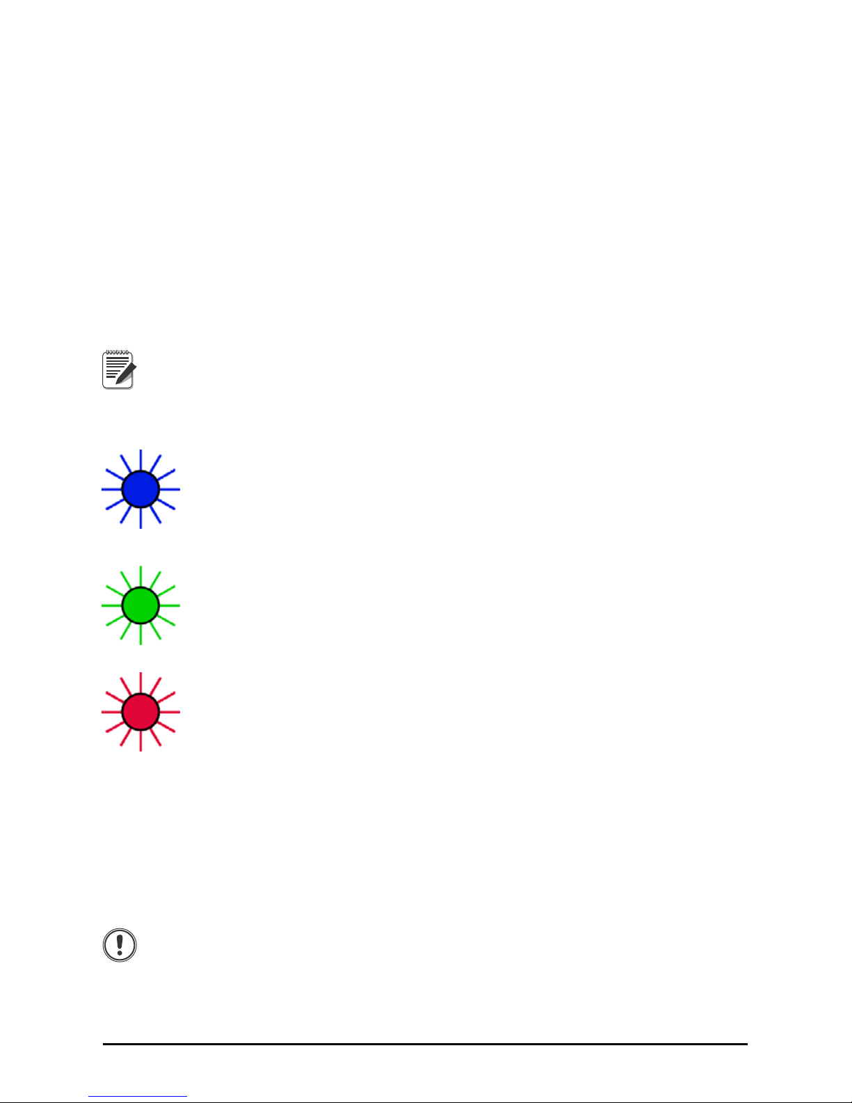
1.11 Charger LED Modes
Blue light - indicates that a charge is in progress. Charging time varies from
one hour to six hours depending on the charge level of the battery when the
charger is first applied. If the charger is attached as soon as the BT
annunciator lights, then charge time will average three hours. It is OK to
remove the battery charger while the blue light is on, but a complete charge
will not be applied.
Green light - indicates the battery is fully charged. The powered charger can
be left connected to the MSI-8000 continuously. MSI recommends leaving
the MSI-8000 on the charger when not in use.
Red light - indicates a fault. Faults include over temperature, under
temperature (the battery must be warmer th
an 14°F (-10°C)), a severely
depleted cell or charge time-out. When the charge times out a trickle charge is
applied to the battery. To clear a time-out fault, unplug the charger and then
plug it back in. A severely discharged cell may take days on the charger to
recover.
1.12 Battery Longevity
The Lithium Polymer Single Cell Battery used in the MSI-8000 has a rated number of
charges of ≥300 before capacity starts to degrade. The charging life can be greatly
increased by charging the battery more often, and not let it reach the battery cutoff voltage
of 3.0V. The battery voltage can be seen by pressing a Function key programmed as
“Test”, the battery must be replaced by an MSI certified technician.
Important
If the MSI-8000 is not in use, it is recommended that the charger is left
attached to keep a charge. The MSI-8000 uses a small current when
powered off which has the potential to deep discharge the batteries.
Never store the MSI-8000 with a depleted battery. This can cause
permanent damage to the battery and require factory replacement.
Shelf life with a fully charged battery is approximately three months.
Page 14

10 MSI-8000 Operator’s Manual
2.0 Operation
2.1 Power
To turn on the power.
1. Press
POWER
, the LCD will show all segments for a display text and the software
Version number will display.
2. The M
SI-8000 is ready for use.
2.2 Zero
Sets the zero reading of the Scale/Dyna-Link. Take out small deviations in zero when the
Scale/Dyna-Link is unloaded. (See Section 2.3 for zeroing (Taring) package or pallet
weights)
1. Press
ZERO
.
2. The tension reading must be stable within the motion window for the zero function
to work.
3. The M
SI-8000 stores the zero reading, and can restore it even if power fails.
Zero - Rules for Use:
1. Works in GROSS mode or NET mode. Zeroing while in Net mode will zero the
gross ten
sion causing the display to show the negative Tare value.
2. The Scale/Dyna-Link must be stable with
in the Motion window. The Scale/DynaLink will not zero until the Stable annunciator is on. The Scale/Dyna-Link will
“remember” that it has a zero request for two seconds. If motion clears in that time,
the Scale/Dyna-Link will zero.
3. The Scale/Dyna-Link will accept a zero setting
over the full Range of the Scale/
Dyna-Link. Zero settings above 4% of full Scale/Dyna-Link will subtract from the
overall capacity of the Scale/Dyna-Link. For example, if you zero out 100 lb, on a
1000 lb Scale/Dyna-Link, the overall capacity of the Scale/Dyna-Link will reduce to
900 lb plus the allowed over-range amount.
2.3 Tare
In force measurement applications, tare is a useful way to display differential force. By
“Taring Out” a known force, only positive or negative deviations from the tared force are
displayed. This can also increase accuracy as any initial error is removed leaving only
slope error. In scale applications, tare is typically used to zero out a known weight such as
rigging, a container, or pallet and display the load in NET tension/weight. The TARE
function in the MSI-8000 is defined as a Tare-In, Tare-Out operation. The first press of the
TAR E key stores the current tension/weight as a tare value and then the Scale/Dyna-Link
subtracts the tare value from the gross tension and changes the display to NET mode. The
next press of the
TAR E key will clear the Tare value and revert the display to GROSS
mode. The optional RF Remote Display has a TARE key permanently available.
Page 15

Operation 11
To Tare and display the NET tension
1. Press
TARE
, the tension reading must be stable within the motion window for the
tare function to work.
2. The Dyna-Link digits display - and the tension mode changes to NET.
3. The backup memory in the MSI-
8000 stores the tare reading, and can restore it even
if power fails.
To Clear the Tare and revert to Gross Tension
1. Press
TARE
, the NET annunciator turns off.
2. Absence of the NET annunciator is the only indication that you are in Gross Tension
mo
de.
Note
To view the Gross tension without clearing the Tare Value, program a
function key to the function “NET/GROSS.”
Tare- Rules for Use:
• Only positive gross tension readings can be tared.
• The stable annunciator must be on. The tension/force reading must be stable.
• Setting or changing the tare has no effect on the Gross zero setting.
• Taring will reduce the apparent over range of the sc
ale. For example, taring 100
pounds of rigging on a 1000 lb scale, the scale will overload at a net tension of 900 lb
(1000-100) plus any additional allowed overload (usually ~4% or 9d).
Page 16

12 MSI-8000 Operator’s Manual
3.0 User Defined Function Keys
The following function descriptions are for optional user defined functions that are
programmed on the three front panel USER keys (F1,F2 & F3). To enable the USER key
functions, you must set up the USER keys following the procedures in Section 4.0. Note
that Function Key setup on the MSI-8000
is independent of the Function Keys of the
connected Scale/Dyna-Link.
Note
In software release 1-XX, F3 is dedicated to the print function and cannot
be changed. The functions PRINT (F3) and
TARE are available full-time on
the MSI-8000 so, although possible, you do not need to program a
Function key for those functions.
Off
No USER Key Function assigned. The F-Key is disabled.
Test
The
TEST function provides an LCD test that lights all LCD segments and the LEDs, then
the model number (8000), the software version number, the battery level, and then a
display test counting from 00000 to 99999. Other internal tests are performed and if any
test fails an error code will display. See Section 6.2 for a description of all error codes. The
TEST can be aborted anytime by pushing ZERO. The test can also be single stepped by
pushing F2 and then using the F1 key to step from display to display.
Total
Note
The Total Mode must be programmed from the Setup Menus before the
USER key will function. See Section 4.1. This feature should not be
confused with the ttl.rd (Total Remote Devices) function, which will add
weight from two or more load sensors.
For accumulation of multiple weighments, the accumulator uses the displayed tension, so
GROSS and NET readings can be added into the same TOTAL.
There are four modes of totalizing: Manual and three Auto Modes.
The Manual Mode requires the TOTAL button to be pressed with
the tension on the scale.
The tension will be added to the previously accumulated value. This assures that a weight/
tension on the scale is only added to the total once. Both the manual and three auto total
modes require that the tension on the scale return below 0.5% (relative to full scale) of
GROSS ZERO or NET ZERO before the next weighment can be added. Applied tension
must be
>1% of capacity above GROSS ZERO or NET ZERO before it can be totaled.
Manual Total
The
Fx-TOTAL key under the MANUAL TOTAL mode functions in this manner:
Tension is > 1% of capacity and has not been totaled - Pushing the
Fx-TOTAL key will add
the current tension to the TOTAL weight. The Fx LED blinks to indicate the tension value
was accepted. The TOTAL LCD annunciator and the Total weight is displayed for ~5
seconds and then the number of samples are displayed for ~2 seconds.
Current Tension has been Totaled - Pushing the
Fx-TOTAL key functions as “View Total”
only and functions as View Total until the 1% threshold is exceeded to allow the next
addition to the total value.
Page 17

User Defined Function Keys 13
Auto Total
The Fx-TOTAL key under the AUTO TOTAL mode functions as Auto Total On/ Auto
Total Off.
The Auto Mode has three variations which are programmed in the SETUP menu:
• AutoLoad - Any settled tension above the ‘Rise above’ threshold will be
automatically totaled. Then the scale must fall below the ‘Drop below’ threshold
before another total is allowed.
• AutoNorm - This mode takes the last settled tension to auto total with. The total
occurs only once the Scale goes below the threshold. This allows the load to be
adjusted without a total occurring. Once load is removed, the Scale uses the last
settled reading for total.
• AutoHigh - Similar to the AutoNorm mode except the Scale uses the highest settled
reading. Useful for loads that can’t be removed all at once.
View Total
The Fx-VIEW TOTAL key activates the Total weight display followed by the number of
samples. While the display is showing the Total, Total is cleared by pressing ZERO.
Net/Gross
Switches the display between Net and Gross modes. Net Tension is defined as Gross
Tension minus a Tare Weight. To switch between Net Mode and Gross Mode press the
Fx-
NetGross
key (setup to the Net/Gross function).
The Fx-NetGross key will only function if a Tare value has been established.
Switching back to Gross mode from Net mode will not clear the Tare value. This allows
the operator to use the Gross Mode temporarily without having to reestablish the Tare
value. Only clearing the Tare or setting a new Tare will change the tare value held before
switching into Gross Mode.
Peak Hold
Peak Hold automatically updates the display when a higher peak tension reading is
established. The Peak Hold function uses a high speed mode of the A/D converter (220
samples) allowing it to capture transient tensions at a far higher rate than typical
Dynamometers. Peak hold is cleared and re-enabled with the
Fx-Peak Hold Key. When a
new peak is detected, the Fx LED will flash three times. The accuracy of the system in
Peak Hold mode is slightly reduced to .2% of Capacity + 5d. The Filter setting is turned
off while in Peak Hold mode to ensure the fastest acquisition rate.
Example Peak Hold Application-
The Peak Hold function is useful in “Dynamic” and “Fall” tests. Common tests for fiber
rope include “Overall Breaking Strain” (OB€), Breaking Force, and Cycled Breaking
Strain. The MSI-8000 combined with a force test stand, meets the speed and accuracy
requirements to properly conduct these tests.
Page 18

1) Program a function key to Peak
Hold (P-Hld)
In this example we’ll use F1 for Peak
Hold.
2) Prepare the test stand and test
sample.
3) Press ZERO to zero out any
residual strain on the link.
4) Press F1 PkHold Confirm that
the “Pk” annunciator is on.
A small jump in the reading may occur
depending on the stability of your test
stand.
5) Apply the test force. The F1 LED
will blink three times for every
new peak it detects.
6) When the test force is removed,
the Peak value can be recorded.
7) To run a new test, press
F1 PkHold to clear the Peak
Value. Confirm the “Pk”
annunciator is off. Then repeat
steps 3-6.
Peak Hold
kg
lb
M
kN
Ton
kg
lb
M
kN
Ton
Pk
kg
lb
M
kN
Ton
kg
lb
M
kN
Ton
Pk
Example Peak Captured Value
Peak Hold
kg
lb
M
kN
Ton
kg
lb
M
kN
Ton
kg
lb
M
kN
Ton
kg
lb
M
kN
Ton
Peak Cleared Value
Capture Peak Force
F1
F1
0
ZERO
See Function Key
Setup on Section 4.2
14 MSI-8000 Operator’s Manual
Figure 3-1. Capture Peak Force
2-Units/ 5-Units
The
Fx-2.Unit key will switch the force units between pounds force and kilograms force.
Selecting the
Fx-5.Unit setting will scroll through all available units: lb, kg, Tons (US
Short), Metric Tons, and kiloNewtons.
Page 19

User Defined Function Keys 15
Hi-Res
Only available with the MSI-7300 Dyna-Link (refer to the Dyna-Link manual PN 152160)
Pressing the Fx-HiRes key puts the display into a temporary high resolution mode. The
high resolution mode continues until the
Fx-HiRes key is pressed again, or power is
cycled. While in the Hi-Res mode the appropriate
Fx LED will blink continuously at a
slow rate.
Hi-Res mode does not increase the accuracy, but allows for smaller weight incrementation
to be displayed. Use Tare or the
ZERO key to zero out any initial error.
Hi-Res Mode will make the MSI-8000 more sensitive to motion and movement resulting
in a less stable display. When Hi-Res is on, the filter is automatically set to the Hi-1 setting
(if Hi-2 is already set, then the filter is not changed). This will have a small effect on
settling time. When Hi-Res is turned off, the filter setting resets to the previous filter
setting.
Print
Pressing the F3-Print key outputs a configured text string to the RS-232 port on the base of
the Dyna-Link. If an F-Key is programmed as Print and the Print Setup is configured as
continuous, then the
F3-Print key is used for Start Print/Stop Print. See Section 5.6 for
more details on data output. The Print function is always available on the MSI-8000, so it
is not necessary to program an F1 or F2 to “Print” then pushing F1 or F2 on the scale will
cause the Comm Port on the Remote to output the selected data string.
Scan
Pressing the Fx-Scan key displays RF connected channels in order.
Total Remote Devices
Pressing the Fx-ttL.rd key displays the summed weight of RF connected sensors. Sensor
summing must be enabled in the COMM Setup Menu. If the “Pairs” or “Both” modes are
enabled in the COMM Setup menu, then pressing the
Fx-ttL.rd key will scroll through the
available combinations.
It is a common setup to program F1 for SCAN and F2 for “ttl.rd” (Total Remote Devices)
to allow quick switching between individual channel displays (with ) or the summed
weight (with “ttL.rd”).
Tare
The Fx-Tare key is redundant in the MSI-8000 since it has a permanent TAR E key. This
was done for consistency across the ScaleCore based product line. There is no need to
program a function key to “TARE.”
Page 20

16 MSI-8000 Operator’s Manual
4.0 Set Up
4.1 Menu Map
)YQF
)YQF
$2))
2))
Off
Test Display
Total
View Total
Net/Gross
Peak Hold
2 Units
5 Units
Hi Res
Print
Tare
Scan
Total Remote
Devices
F1 & F2 KEY
FUNCTIONS
F2 Key F1
F2 Key F2
Auto Off Time
SETUP MENU
Disabled (default)
15 minutes
30 minutes
45 minutes
1 hour
AUTO OFF TIME
With the Power On, press the F2
key and Power key simultaneously
F2
2))
W(6W
WRW$O
YWWO
Q(W*U
3+/G
8QLW
8QLW
+LU(6
3ULQW
W$UH
6F$Q
WWOUG
Figure 4-1. Menu Map
Page 21

Set Up 17
4.2 Function Keys
The MSI-8000 has 2 user definable function keys on the Front Panel that can be
programmed to any of several functions. F1 is defaulted to Peak Hold and F2 is
defaulted to Test. F3 is currently fixed to the Print function. For operational details of
each function, refer to the Scale/Dyna-Link Operator’s Manual. Function keys on the
MSI-8000 are independent of any Function Key setup on the Scale/Dyna-Link.
)YQF
SCROLL
SCROLL
SCROLL
SCROLL
SCROLL
ENTER/SELECT
ENTER/SELECT
WRWD/
blinking
QHW*U
blinking
3+OG
blinking
2II
blinking
2II
blinking
1)
With the MSI-8000 on, press the
F2 key and the POWER key
simultaneously.
2)
The first item of the Setup Menu
is “Func1”.
To setup F2 instead of F1, scroll to the
next menu item by pressing F2.
3)
To setup the F1 key press F1.
The current F1 key function is
displayed.
4)
Select the F1 key function by
scrolling through the choices with
theF2 key. See the list of
available functions on the Setup
Menu Map.
This procedure scrolls through all
available choices for illustration
purposes only.
In this example, we’ll set F1 to the TEST
function.
5)
When the desired F1 Key
function is displayed, press F1
.
The next item in the Setup Menu
appears.
6)
Either press ZERO to exit Setup
and store all changes, or
continue to another Setup Menu
item using the F2 Key.
Function Key Setup
)YQF
Next Setup Menu Item
Store and return to
weight display
6WRUH
SCROLL
SCROLL
SCROLL
SCROLL
SCROLL
SCROLL
7HVW
blinking
6FDQ
blinking
XQLW
blinking
WDUH
blinking
YWWO
blinking
EXIT/SAVE
ZERO
0
Press Simultaneously
SCROLL
XQLW
blinking
SCROLL
+LUHV
blinking
3ULQW
blinking
WWOUG
blinking
SCROLL
SCROLL
WHVW
blinking
0
F1
F2
Exit and Cancel Changes
Exit and Save/Back 1 Level
Enter / Select
Scroll
In Menu Key Functions
Figure 4-2. Function Keys
Page 22

18 MSI-8000 Operator’s Manual
4.3 Auto-Off
The A-OFF feature, when enabled, prolongs the battery life by turning POWER off
when the scale is not in use. Any time any button is pressed, or the detected tension is
in Motion exceeding 10d, the time limit is reset. Therefore, the MSI-8000 will stay on
indefinitely if the tension is changing or any button is pressed at least once. With AOFF disabled, it will remain on; only pressing POWER will turn it off (or when the
battery is depleted).
1)
With the MSI-8000 on, press the
POWER and the F2 keys
simultaneously.
2)
The first item of the Setup Menu
is “Func1”. Scroll to “A-OFF” with
the F2 key.
3)
To setup the A-Off timing, press
F1. The current Auto-Off time is
displayed.
4)
Select the Auto Off time by
scrolling through the choices with
the F2 key.
In this example, we’ll set 60 minutes as
the Auto-Off time.
5)
When the desired time is
displayed, press F1. The next
item in the Setup Menu appears.
6)
Either press ZERO to exit Setup
and store all changes, or
continue to another Setup Menu
item using the F2 Key.
Auto-Off Setup
)YQF $2))
Press Simultaneously
SCROLL
SCROLL
SCROLL
SCROLL
SCROLL
ENTER/SELECT
EXIT/SAVE
ZERO
0
ENTER/SELECT
2II
blinking
blinking
blinking
)YQF
Next Setup Menu Item
Store and return to
weight display
6WRUH
blinking
blinking
SCROLL
Figure 4-3. Auto-Off
Page 23

COMM Set Up 19
5.0 COMM Set Up
The MSI-8000 uses 802.15.4 transceivers to communicate between MSI’s Dyna-Links and
Crane Scales.
802.15.4 operates in the 2.4GHz systems if:
• Caution is taken to isolate antennas at least 10 feet (3 meters) from the MSI-8000
equipment.
• MSI-8000 based RF systems are peer to peer. For multiple scale connections, the MSI-
8000 acts as the network coordinator.
The MSI-8000 uses three numbers to establish a piconet:
• ScaleCore ID - This number is used to uniquely identify each device in a Piconet. It
has a range of 0-254 and must not be duplicated within the same RF Channel. For the
MSI-8000 as network coordinator, MSI recommends a number from 20-30.
• RF Channel - Establishes the base network that all interconnected devices must
match. This number must be in the range of 12-23.
• Network ID - This is a 64 bit number that all interconnected devices must match. The
MSI-8000 limits this number to a max of 6 digits for a range of 0-99999. Do not use a
small number here to help avoid other 802.15.4 networks that default to a Network ID
of 0.
For all devices that must interconnect, the RF Channel and Network ID must match. The
ScaleCore ID must be unique. The Dyna-Link or Crane Scale that is the weight source
should be set to a ScaleCoreID of 0. Then if other slave devices are added, they can be
added in sequence. The MSI-8000 ID is recommended to be in the range of 20-30.
Page 24

0
F1
F2
Exit and Cancel Changes
Exit and Save/Back 1 Level
Enter / Select
Scroll
In Menu Key Functions
PRINT STRINGS
6WUQ*
&QWUO
5DWH
2II
8VHU
/RDG
&RQW
Off(default)
F key
On Stable Load
Continuous
PRINT
CONTROL
Print String Output Rate
Number entry screen
(0-65535 seconds)
Print String Format
Number entry screen
1= Current Wt (Wt-Unit-Mode )
2= Net Wt (Wt-Unit-Net )
3= Gross Wt (Wt-Unit-Grs )
4= Tare Wt (Wt-Unit-Tare
)
5= Total Wt (Wt-Unit-Total )
6= Total Count (#Samples-TCNT
)
7= Current Wt (no units or mode )
8=
(Reserved)
9= CR-LF (
)
Affects continuous mode
only
3ULQW
U)
F)QHW
Print
RF
Configure
Network
2Q2II
FLG
&KQO
QHWLG
Enable RF
ScaleCore ID
RF Channel
Network ID
RF
SETUP
Setup Strings
Print Control
Output Rate
Network ID
2Q
2II
Range 1-254, (20-30)
Range 12-23
Range 0 to 999999
RF Network
Number entr
y
screens
W0RUG
WWOUG
Total # of RD’s
Total RD’s
(Remote Sensor
Devices)
CONFIGURE
NETWORK
Range 1-4
(default 1)
$OO
3ULUV
ERWK
2II
Sum all Remote Devices
Sum in Pairs
(requires 4 Remotes)
Sum in Pairs + Grand Total
Off, summing disabled
SUM REMOTE SENSOR DEVICES SETUP
F2
Press Simultaneously
6WU(Q
Transmission
Strength
Range 0 to 4
.
20 MSI-8000 Operator’s Manual
Figure 5-1. COMM Set Up Menu
Note
Transmission Strength should be set to the lowest setting possible to
achieve the transmission required. Both the scale/Dyna-Link and the 8000
should be set at the same transmission strength setting.
Table 5-1. Transmission Strength Settings
Setting
RF Power
Level
Tra nsm it
Current
Note
0 10dBm 137mA Lowest Transmission Power
1 12dBm 155mA (default on 7300s and 8000s)
2 14dBm 170mA
3 16dBm 188mA
4 18dBm 215mA
Page 25

COMM Set Up 21
5.1 RF Setup
2Q2II
2Q
1) With the power on, open the
Comm Setup Menu by
pressing the F1 and F3 keys
simultaneously.
The COMM Setup Menu
appears. The first menu
choice is “Print”.
2) Press F2 to scroll to the RF
Setup menus.
3) Press F1 to enter the RF
setup menu.
4) The display reads “OnOff”
Confirm the 8000 RF is on
by pressing F1. If it is off,
use the F2 key to change it
to on. Then push F1.
Off is only used when the 8000 is
hardwired to a Dyna-Link.
5) Press F1. Next the “Scid”
(ScaleCore ID) screen is
shown
6) Press F1. The current Scid
number is shown.
If the offered Scid value is correct,
push F1 and jump to step 10.
In this example we’ll enter 28 as an
SCID number. Any value from 1-254
is acceptable. However, MSI
recommends a value from 20 – 30.
7) To input the SCID value,
press F2 to start the number
entry process.
8) Use F2 to change the
number, and F1 to enter
the number. Add the next
digit by pushing F2 and
scrolling as required.
Repeat this sequence
until the entire SCID
number is entered.
9) Once the entire SCID
value is entered, press F1
to finalize the number.
10) The next RF Setup
parameter is “ChnL”
(Channel). Press F1 to start
the number entry process.
3ULQW
RF Setup Procedure
VFLG
ENTER/SELECT
ENTER/SELECT
SCROLL
U)
example ScID Value
ENTER/SELECT
8 times
fixed
blinking blinking
blinking
blinking
SCROLL
SCROLL
SCROLL
F2
ENTER/SELECT
Error Correction: If you input a wrong value, press ZERO to step
back one digit and reenter.
ENTER/SELECT
fixed
ENTER/SELECT
&KQ/
ENTER/SELECT
Press Simultaneously
SCROLL
ENTER/SELECT
0
F1
F2
Exit and Cancel Changes
Exit and Save/Back 1 Level
Enter / Select
Scroll
In Menu Key Functions
Figure 5-2. RF Set Up
Page 26

11) The current RF Channel
number is displayed.
If the offered RF Channel value is
correct, push F1 and jump to step
14.
12) Press F2 and using the
previous process, enter
the RF Channel number.
Recommended RF Channel numbers
range from 12 to 23. In this example
we’ll use 21 as the RF Channel.
13) When the desired RF
Channel number is
shown and fixed, press
F1.
14) The next RF Setup Menu
item is the “nEtid”
(Network ID). Press
F1
to see the current Net ID
number.
If the offered Network ID value is
correct, push F1 and jump to step
17.
15) Using the numeric entry
process as before, input
a network ID number.
Press F2 to start a new
number.
Allowed Network ID numbers range
from 0 to 99999.
MSI recommends
a random number of at least four
digits to ensure that the 8000
system won’t conflict with any
other 802.15.4 networks.
QHWLG
blinking
blinking
fixed
SCROLL
ENTER/SELECT
ENTER/SELECT
blinking
SCROLL
SCROLL
blinking
blinking
fixed
ENTER/SELECT
ENTER/SELECT
current Net ID blinking
SCROLL
blinking
example value only
SCROLL
Repeat number
entry procedure
16) When the final number is
shown and fixed, press
F1 to store the network
ID.
20) The RF setup menu goes
to the first menu, OnOff.
Press the ZERO key to
exit out of the RF setup
menus.
21) Press ZERO again to exit
the COMM setup menu
and store the new RF
network numbers.
6WU(Q
ENTER/SELECT
F1
3ULQW
6WRUH
2Q2II
ENTER/SELECT
F1
0
EXIT/SAVE
ZERO
0
EXIT/SAVE
ZERO
blinking
ENTER/SELECT
F1
17)
The menu displays StrEn.
Pr
ess the F1 to enter.
Press F2, using the
numeric entry process,
input
a
transmission
strength number
.
19) When the desired number
i
s displayed, press F1 to
store the number.
18)
22 MSI-8000 Operator’s Manual
Figure 5-3. RF Set Up (Continued)
Page 27

COMM Set Up 23
5.2 RF Set Up, Dyna-Link And MSI Crane Scales
Setting up the MSI-7300 Dyna-Link and other 802.15.4 linked MSI Crane Scales is the
same procedure except for the two button entry method.
MSI-7300 Dyna-Link 2 - P
ress F1 and F2 simultaneously.
MSI-3460 Challenger 3 - Press
TAR E and USER simultaneously.
The 3460 does not have a Print Function. Printing is only available on the linked
MSI-8000.
MSI-4260 Port-A-Weigh -
Press TAR E and USER simultaneously.
Note
The 4260 does not have a Print Function when the Radio Link is installed.
Printing is only available on the linked
MSI-8000
.
The Net ID and RF Channel must exactly match the MSI-8000. The ScaleCoreID (SCID)
must be unique. The first Scale/Dyna-Link must have a SCID of 0. In multiple link
systems, setup sequential SCIDS starting at 0.
5.3 MSI8000 With Multiple Sensors
The MSI-8000 can monitor up to four load sensors (MSI-7300 Dyna-Links are shown, but
MSI-3460s and MSI-4260s can also be used). The sensors are readable individually, in
pairs or summed.
5000 lbs / 2500 KG
MAXIMUM CAPACITY
7300
lb
5000 lbs / 2500 KG
MAXIMUM CAPACITY
7300
lb
SC 0
SC 1
Pair1
(Sum) All
5000 lbs / 2500 KG
MAXIMUM CAPACITY
7300
lb
5000 lbs / 2500 KG
MAXIMUM CAPACITY
7300
lb
SC 0
SC 1
Pair1
5000 lbs / 2500 KG
MAXIMUM CAPACITY
7300
lb
SC 2
(Sum) All
5000 lbs / 2500 KG
MAXIMUM CAPACITY
7300
lb
5000 lbs / 2500 KG
MAXIMUM CAPACITY
7300
lb
SC 0
SC 1
Pair1
5000 lbs / 2500 KG
MAXIMUM CAPACITY
7300
lb
5000 lbs / 2500 KG
MAXIMUM CAPACITY
7300
lb
SC 2
SC 3
Pair2
(Sum) All
Setting up a multiple sensor network requires the following:
1. Each sensor has a unique SCID. The IDs must be co
nsecutive, starting with 0. This is
set in the sensor setup, not in the 8000. See the appropriate User Guide.
2. Using the “Configure Network Menu” [arrow] “T
otal Number of RDs,” set the
number of remote sensor devices (RD). This number does not include the MSI-8000
or any modems. So the range is 2-4.
3. Setup the desired summing mode using the “Total RDs” menu.
4. Program F1 to the “Scan” function, and F2 to the “ttl.rd” function if summed sensor
readings are needed.
Monitoring of more than 4 sensors is possible
with modified software. Contact MSI for
information.
Page 28

lbkN
MTon
1) Program a function key to Scan.
In this example we’ll use F1 for Scan.
2) The current channel is displayed.
Press F1 Scan to change the
display to the next channel.
3) The display briefly displays the
scan channel number. Then the
scan channel weight is
displayed.
4) Press F1 Scan. In a two sensor
system the scan returns to the
first channel, 0.
SCAN
See Function Key setup
on page 15.
lb
MkNTon
6F
Scan Weight Inputs
6F
SCAN
MOMENTARY
MOMENTARY
kg
lb
M
kN
Ton
F1
F1
kg
24 MSI-8000 Operator’s Manual
Figure 5-4. Scan Weight Inputs
5.4 Summing Modes
The summing modes are straight forward and useful for the majority of overhead lifting
applications.
5.4.1 Modes
ALL
All channels are added together. Using the
Fx ttl.rd function key, the sum of all connected
sensors are displayed. Pressing the Fx ttl.rd again will confirm that you are observing the
summed channels by briefly displaying “ttl.rd” (total remote sensor devices).
Note
If the sum is the only thing the user wants to observe, disable the Scan
function key using the function key setup menu.
PAIRS
Primarily intended for 4 sensor systems. When scrolling through the channels with an Fx
ttl.rd
, the channels will be presented as separate weights first and then as pairs. This
display is proceeded by the LCD message “Pair1” and “Pair2.”
BOTH
This mode shows both the pair totals and the overall total. Each press of the
Fx ttl.rd key
will scroll through the summed combinations. First “Pair1,” next “Pair2,” then the sum of
all connected sensors is displayed.
OFF
Sensor summing disabled. Even if a function key is set to “ttl.rd” nothing will happen.
Page 29

1)
Program a function key to “ttl.rd”
(Total Remote Devices).
In this
example we’ll use F2 for “ttl.rd”.
2)
The current channel is displayed.
Press F2 ttl.rd to change the
display to the summed total.
3)
The display briefly displays
“AddAll”. Then summed total
weight is displayed.
4)
Subsequent presses of the
F2 ttl.rd key will show all enabled
sum types.
TOTAL REM
DEVICES
See Function Key setup
on page 15.
kg
lb
M
kN
Ton
$GG$O
View Summed Channels
MOMENTARY
TOTAL REM
DEVICES
3DLU
TOTAL REM
DEVICES
3DLU
MOMENTARY
MOMENTARY
kg
lb
M
kN
Ton
kg
lb
M
kN
Ton
kg
lb
M
kN
Ton
F2
F2
F2
COMM Set Up 25
Figure 5-5. View Summed Channels
5.5 Behavior Of Zero And Tare In Multiple Channel Systems
Whatever channel that is displayed is considered the “Focus Channel.” Pressing the ZERO
or TA RE keys will only affect the displayed channel. When displaying summed channels,
zero and TARE commands will be sent to all devices that contribute to the displayed
weight. For example, if in the “BOTH” mode, and you are displaying Pair 1 (the sum of
SC0 and SC1), pressing
ZERO will zero only SC0 and SC1. If displaying the grand total
using the ALL mode, then pressing ZERO will zero all connected sensors.
Using the TARE function: If one device is
tared in the individual display mode, the
summed weight will be the sum of a Net weight and a Gross weight. If the TARE key is
pressed when displaying any of the summed modes, all devices that add to form the
current display are Tared and placed in Net mode.
5.6 Printer Set Up
The RS 232 Comm Port is capable of outputting tension data. All the weight modes the RF
linked weight device can measure are available in user formatted form. The control Mode
programs are what cause the MSI-8000 to print.
The modes are:
1. Assigned F-Key is pressed, one transmission of the selected string type is output.
2. On Load - When the tension on the link is stable, one transmission will output. Then
the ten
sion must return to zero to enable another print output.
3. Continuous - Program the interval in seconds up to 65,535 seconds. Setting the
in
terval to 0 will set an interval as fast as the system can go. To disable printing set
the control mode to “OFF.”
The Comm Port settings are indep
endent of any print settings in connected scales. They
reside only in the MSI-8000.
Page 30

26 MSI-8000 Operator’s Manual
5.7 Control Modes
The user can select four control modes:
• User
- Printing is controlled by the operator pushing the PRINT key (usually F3).
• Load - One print
output when a stable load is reached. The scale must return to near
zero before another print will occur. Other configurations of “On Load” are available
using the SCCMP program (ScaleCore Configuration Management Program).
• Cont
inuous - The MSI-8000 will continuously output the data at a rate controlled by
the “rAtE” (RATE) menu.
• Off - Prin
ting is disabled. Power consumption is lower with print off.
5.8 Standard Print Strings
Figure 5-6. Standard Print Strings
1 Current
Te ns io n
Fixed output length: 16. Leading zeros suppressed except for the LSD.
TTTTTTTspUUspMMMMMcrlf
Where TTTTTTT is tension data with -sign if necessary. UU is the
units, MMMMM is the tension mode which for “1” is either NET or
GROSS
2 Net Tension Fixed output length:16. Leading zer
os suppressed except for the LSD.
TTTTTTTspUUspNETspspcrlf
3 Gross
Te ns i on
Fixed output length: 16. Leading zeros suppressed except for the LSD.
TTTTTTTspUUspGROSScrlf
4 Tar e W ei gh t Fixed output length:16. Leading zer
os suppressed except for the LSD.
TTTTTTTspUUspTA REcrlf
5 To ta l
We
ight
Fixed output length: 16. Leading zeros suppressed except for the LSD.
TTTTTTTTTspUUspTTLcrlf
6 Number of
Samples
To
ta l ed
Fixed output length: 16. Leading zeros suppressed except for the LSD.
spspspspspsp
SSSSSSSspT- C N Tspcrlf
7 Current
Weight
Mode
Net, Gross, Peak, etc
sp
MMMMMcrlf
8/9 Carriage
Retur
n/
Line Feed.
Used to add a space between print records.
crlf
In the string number entry screen, you can enter combinations of the standard print strings.
For example, to get a NET GROSS TARE printout with a space between records, simply
enter “2349.”
Using SCCMP application, custom output strings are possible. See the SCCMP
programm
ing guide for details.
The serial output is configured as 9600 baud, Xon/Xoff handshaking, no hardware
hand
shaking, 1 stop bit, no parity. Other baud rates are possible by special order only.
Page 31

1) With the MSI-8000 on, press the
F1 key and the F3 keys
simultaneously.
2) The LCD shows “Print”. Press
F1.
3) The sub-menu item “StrnG”
(String) appears. Press F1
.
4) The current Print Mode format
number is displayed.
5) Setup a print format with one or
more digits representing the data
type required for the print output.
In this example, we’ll set the Print format
for a Net, Gross, Tare output with a
carriage return/line feed between each
print output. The number entry required
will be 2349. The 2 is for Net weight,
the 3 for Gross weight, the 4 for Tare
weight, and the 9 inserts a space before
the next print output.
6) Using the F2 Key, scroll through
the digits until the desired digit
is shown, then press F1 to enter
the digit value. Repeat for the
remaining digits.
7) When the entire number is
displayed press F1. The next
item in the Print menu appears,
“Cntrl”.
8) Press F1 to enter the Print
Control Menu. The last set control
mode will appear.
9) To change the print control mode,
press F2.
In this example, we’ll set the Print Control
Mode to Continuous.
10) Press F2 key until the desired
print control mode is shown.
11) When the desired print mode is
shown, push F1 to save. The
next Print setup item, “rAte”
appears. If you have set
Continuous (Cont) as your print
control, proceed to step 12). For
any other Control mode jump to
step 15
Printer / Output Setup
blinking
blinking
fixed
fixed
fixed
&QWUO
ENTER/SELECT
ENTER/SELECT
ENTER/SELECT
Next Print Menu Item
3ULQW
6WUQ
ENTER/SELECT
ENTER/SELECT
blinking
SCROLL
SCROLL
ENTER/SELECT
ENTER/SELECT
xed
blinking
SCROLL
SCROLL
Example Value
blinking
SCROLL
blinking
ENTER/SELECT
2))
SCROLL
2))
SCROLL
8V(U
Function Key PrintsPrint is disabled
SCROLL
/R$G
SCROLL
&RQW
Function Key PrintsPrint is disabled
UDWH
Next Print Menu Item
ENTER/SELECT
1= Current Wt (Wt-Unit-Mode )
2= Net Wt (Wt-Unit-Net
)
3= Gross Wt (Wt-Unit-Grs )
4= Tare Wt (Wt-Unit-Tare
)
5= Total Wt (Wt-Unit-Total )
6= Total Count
(#Samples-TCNT
)
7= Current Wt
(no units or mode
)
8= (Reserved)
9= CR-LF ( )
Press Simultaneously
0
F1
F2
Exit and Cancel Changes
Exit and Save/Back 1 Level
Enter / Select
Scroll
In Menu Key Functions
COMM Set Up 27
Figure 5-7. Printer/Output Set Up
Page 32

12) Press F1 to enter the Print rate
number entry screen. The current
print rate appears on the LCD.
In this example, we’ll set the Print Rate
to an output rate of once every 2
seconds.
13) PressF2 to change the Print rate.
Use F2 to scroll the number,
enter each number with the F1
key.
14) When the entire number is
displayed, press F1 again to
finalize the seconds entry. The
next Print Menu Item appears,
“String”.
15) Exit the Print Setup Menu by
pressing ZERO twice. The
message “Store” appears briefly
then normal system operation
starts.
ENTER/SELECT
blinking
Example Value
blinking
SCROLL
blinking
fixed
ENTER/SELECT
SCROLL
ENTER/SELECT
6WUQ
EXIT/SAVE
ZERO
0
EXIT/SAVE
ZERO
0
3ULQW 6WRUH
The number represents the print
interval rate in seconds. Use 0 for the
fastest the MSI-8000 can go (~5 times
per second). To set a once a minute
transmission, set the rate to 60. To
set once per hour, set the rate to 3600, etc. Largest possible
entry is 65535 which is >18 hours.
28 MSI-8000 Operator’s Manual
Figure 5.6 Printer/Output Set Up (continued)
5.9 COMM Port Hardware
The MSI-8000 RS-232 Comm Port is used for software updates, connecting to a remote
display and for connecting to any RS-232 device.
Connector:
M12 industrial IP67 rated. An adapter cable (MSI P/N 503489) is required to
connect the MSI-8000 to a computer. This adapter cable converts the 8000 connector to a
standard D9 serial connector. The 503489 cable can be converted to DTE by using a Null
Modem adaptor.
Data Configuration: T
he data output is fixed at 8-1-N.
Baud Rate: Pro
grammable for 300 to 230.4<baud in 8 steps. The bootloader for updating
software is always 38.4k baud
Handshaking: No
hardware handshaking is supported. Xon/Xoff software handshaking is
always on.
It may be necessary to disconnect the shield drain wire at the D-9 connector frame to
prev
ent ground loops. Ground loops can cause unstable readings. In extreme cases it may
be necessary to use an isolated RS-232 interface.
Serial Cable Schematic, DCE Configuration for connecting
to a computer (503489-0001
schematic).
Page 33

COMM Set Up 29
Serial Cable Schematic, DTE Configuration for connecting directly to a DCE printer or
other DCE devices (503489-0002 schematic).
5.10 Service Counters
All MSI’s RF Linked Scales and Dyna-Links maintain two service counters for safety. The
first counter (LFCnt) counts lifts above 25% of capacity. The second counter (OLCnt)
counts the number of times the RF Linked Scale has been overloaded. These counters
serve to warn the user to inspect the load train after a number of overloads or a long term
frequency of high capacity lifts. Service counters can only be reset by the factory. The
power up routine will be interrupted when the lift counter exceeds 16383 lifts or the
overload counter exceeds 1023 overloads. Push any key to continue operation.
Feature only available on MSI-
8000 Software release 2.00 and above. Service counters are
available on the Scale/Dyna-Link front panel Test function.
Page 34

30 MSI-8000 Operator’s Manual
1) Program a User Function key to
be TEST (see function key setup).
For this example, F1 is
programmed as TEST.
2) Press F1- TEST .
3) Within 2 seconds of pressing the
F1– TEST key, press F1 again
(must be F1 regardless of which key is
programmed as TEST).
The test will sequence through steps 4
to 7 automatically unless you stop it by
pressing F2 immediately. Then using
F1 and F2 each parameter can be
observed statically.
4) The display flashes “LFCnt” (for
Lift Counter) followed by the
number of times the weight has
exceeded 25% of capacity.
5) Next, the display flashes “OLCnt”
(for Overload Counter) followed
by the number of times the
weight has exceeded capacity.
6) Next,the display flashes the CCal value.
7) The Dynalink / Scale returns to
standard weighing mode. If you
interrupted the auto sequence,
press ZERO to return to tension
link mode.
/)&QW
2/&QW
Return to standard weight display
ENTER/SELECT
Number of Lifts above 25% of Capacity
Number of Lifts that exceeded Capacity
example value
example value
Start of Test Sequence
All segments on
&&D/
blinking
blinking
example C-Cal value
Access the Service Counters
Fx
Figure 5-8. Access the Service Counters
Only a MSI factory representative can reset the s
ervice counters, as these are an important
safety warning feature. Depending on the circumstances, a thorough load train inspection
might be necessary to ensure product safety.
Reference MSI’s “Crane Scale Safety and Periodic Maintenance Manual” for proper
load
ing techniques to improve the safety and longevity of your Crane Scale or Dyna-Link.
This publication is available at www.msiscales.com and is included in the CD shipped
with your MSI-8000.
Page 35

Appendix 31
6.0 Appendix
6.1 Troubleshooting
Problem Possible Cause Solution
Display is blank
when POWER
button is pressed
Discharged battery Recharge
Defective battery Replace (factory replacement only
Defective switch or
circuit board
Requires Authorized Service
Display does not
function properly/
Front panel
buttons do not
function normally/
Scale/Dyna-Link
will not turn off.
Improperly loaded
software
Reinstall software
Faulty Circuit Board Requires Authorized Service
Loose Connectors Requires Authorized Service
Scale/Dyna-Link
does not respond
to tension
changes
Out of calibration Calibrate
Faulty load cell Replace
Load cell connector Check connector and wires
Display over
ranges below
100% of capacity
Tar ed Te ns i on is
added to load to
determine overload
point
Return to gross tension mode
Zero requires
adjustment
Rezero the scale
Too much tension/
load has been zeroed
Rezero the scale
Display drifts AZM (Auto0) is turned
off
Tur n AZ M on
Rapid temperature
changes such as
moving the scale from
indoors to outdoors
Wait until the scale temperature has stabilized
Displayed tension
shows large error
Scale not zeroed
before load is lifted
Zero the scale with no load attached
lb/kg units causing
confusion
Select proper units
Requires recalibration Recalibrate
Table 6-1. Troubleshooting
Page 36

32 MSI-8000 Operator’s Manual
Display reading
not stable
Excessive vibration in
crane system
Increase filtering or increase ‘d’ in Cal
Excessive side
loadi
ng
Improve load train symmetry
Load cell faulty Check LC connections
Display toggles
between “Er
ror”
and “Load”
Tension exceeds
capacity
Reduce tension immediately
Faulty Load cell or
wiring
Check LC and LC wiring
Display toggles
between “Error”
and “buttn”
A key is stuck or is
being held down
Check switches for damage
Weight is on the
Scale/Dyna-Link,
RF Remote
Display does not
match
Units not mated See setting the RF Network address
procedures
Lo Batt is blinking Battery is low Recharge Battery
Unit turns on,
then immediately
off
Battery is low Recharge Battery
Tension will not
zero
System not stable
Wait for stable symbol
to turn on
Increase filtering for more stability
Zero out of range Zero range might be limited. Reduce the
tensi
on or use Tare instead
Tension will not
Tare or Total
System not Stable
Wait for the stable symbol
to turn on,
or if in a mechanically noisy crane,
increase the
filtering or reduce the size of the Scale
increment “d.” It is also possible to increase the
motion window. Contact MSI if you have a
problem getting the 8000 to zero, tare, or total
due to stability issues
Set point lights
blin
k
Set point is enabled
and the trigger point
has been reached
Disable set points if they are not needed
Manual Total does
not work
A function key is not
set to “total”
Set up Func1 or Func2 for “total”
Ten s io n m u st be
stable
Increase filtering for more stability
Problem Possible Cause Solution
Table 6-1. Troubleshooting
Page 37

Appendix 33
Auto Total does
not work
Ten s io n m u st be
stable
Wait for stable symbol
to turn on or
increase filtering for mor
e stability
Ten s io n t h re sh o ld s
not r
eached
You must exceed 1% of capacity for autototal
to work. Then you must drop below 0.5% of
capacity for additional weighments to register.
Charger RED light
is on
Battery deep
discharged
Disconnect charger, reconnect. If still red,
charge for 24 hours to see if it recovers.
Disconnect the charger. Open the case and
disc
onnect the cord from the internal charger
board to the display board. Charge for 24
hours. If the charger LED is still RED, the
battery will need replacement. This procedure
is only recommended for experienced
technicians.
Ambient temperature
is t
oo high
The battery charger won’t fast charge in high
ambient temperatures. Place the system in a
cooler environment.
Ambient temperature
is too low (<-20°C,
14°F)
The battery charger won’t fast charge in low
ambient temperatures. Place the system in a
warmer environment
Charger LED
remains blue and
never turns green
The
MSI-8000 is on. Turn off the MSI-8000. While power is being
drawn front the battery, it won’t top off the
battery.
The battery condition
is poor.
Replace the Battery.
Problem Possible Cause Solution
Table 6-1. Troubleshooting
Page 38

34 MSI-8000 Operator’s Manual
6.2 Error Codes
The ScaleCore Processor that is the heart of the MSI-8000 detects errors and generates
error codes to aid in troubleshooting.
Table 6-2. Error Codes
Error Code Definition Comment
LcOFF LC Disabled A Load cell was not enabled
2CAL In Cal The system is in calibration mode. Do not
send
commands unrelated to calibration
unCAL Not Calibrated System has not been calibrated
Error
LoAd
Overload Tension/Weight exceeds Set capacity
+9d, or load cell is damaged or
disconnected.
Error
UndLd
Underloaded Tension/weight is more than 20%
negative, or load cell is damaged or
disconnected.
Page 39

Appendix 35
6.3 Mechanical Dimensions
8.0”
203.2mm
Figure 6-1. Mechanical Dimensions Front View
3.85”
98mm
1.37”
34.8mm
Figure 6-2. Mechanical Dimensions Back View
Page 40

36 MSI-8000 Operator’s Manual
6.4 Firmware Update Procedure
Updating firmware in the MSI-8000 requires the following: a DCE serial cable (MSI
503489-0001, or build per DCE cable schematic on page 28), a PC with a terminal
program (“Teraterm Pro” recommended), and if the PC does not have standard RS-232
serial ports, then a USB to serial converter. Make sure the driver for the USB converter is
properly installed, and that the Terminal program is set up for the proper comm port.
The latest firmware code is available from the MSI Service Department and can be
emailed on request. Your firmware version is displayed when the MSI-8000 is turned on in
form “01-04” (your version will vary). MSI-8000 firmware updates do not require a
recalibration of the connected scale. Consult the version release notes for information
regarding the updated code.
1. Setup the terminal serial port to 8 data bits, No Parity, 1 stop bit, 9600 BAUD, XON/
XOFF (flow control).
2. Connect to the Dyna-Link serial port using the DCE cable. Connect the D9
connector to your PC or USB adapter.
3. (Optional) Test that you have a connection by typing {00FF01?}. If the connection is
good the MSI-8000 will respond with {000001r2;0;01E02;2011-07-08;11:05} or
something similar.
4. On the terminal keyboard, type {ffff09=0199}
5. Change the terminal serial port to 38400 BAUD. Hit the ‘r’ key to refresh the
display. The following menu should appear
MSI-8000 SCALECORE2 BOOT LOADER Ver. 00-05 (c) 2012-05-02 10:55
(u) Download and program application code
(your bootloader version may vary)
(q) query app code info
(g) execute app code
(r) refresh
Your bootloader version may vary
6. Type u
Terminal should display:
Send File NOW, or press ^ to abort:
7. Send the .prg file using the file send feature of your terminal program. The character
“#” will tick away as the ScaleCore programs.
Send File NOW, or press ^to abort:#####################################
##################################################################
##################################################################
##################################################################
###########################################################
Completed
Note
Page 41

Appendix 37
8. After file is received terminal should display “Completed.” Then the boot menu
appears again.
MSI-8000 SCALECORE2 BOOT LOADER Ver. 00-05 (c) 2012-05-02 17:06
(u) Download and program application code
(your bootloader version may vary)
(q) query app code info
(g) execute app code
(r) refresh
9. Optional step: send q to check the program. The ScaleCore will respond with a
message that details the 32b checksum, the product ID and version, and the
Application Code version number in the following form:
Computed Signature 76F481D8
Received Signature 76F481D8
Product ID 07 MSI-8000 product family
Product Version ID 00 Optional features code
App Code Version 01-04 Firmware version number
If the CRC Signature does not match, go back to step 4 and try again.
10.Send an “r” to restore the boot menu.
MSI-8000 SCALECORE2 BOOT LOADER Ver. 00-05 (c) 2012-05-02 10:55
(u) Download and program application code
(your bootloader version may vary)
(q) query app code info
(g) execute app code
(r) refresh
11.Send a “g.” The MSI-8000 should start.
32b CRC must match (76F481D8 is an
example only)
Page 42

38 MSI-8000 Operator’s Manual
The MSI Limited Warranty
MEASUREMENT SYSTEMS INTERNATIONAL, INC., WARRANTS load sensing
elements and meters against defects in workmanship and materials for a period of one year
from date of purchase and warrants electrical cables and batteries against the same defects
for a period of ninety (90) days from date of purchase.
Any device which proves defective during the warranty period will be replaced or repaired
at no charge; provided that the defective device is returned to the Company freight prepaid.
In no event shall the Company be liable for the cost of any repairs or alterations made by
others except those repairs or alterations made with its specific written consent, nor shall
the Company be liable for any damages or delays whether caused by defective
workmanship, materials or otherwise.
The Company shall not be liable for any personal injury or property damage resulting
from the handling, possession or use of the equipment by the customer.
The warranty set forth herein is exclusive and is expressly in lieu of all other warranties,
express or implied, including without limitation any implied warranties of merchantability
or fitness, or of any other obligations or liability on the part of the Company.
The liability of the Company under this warranty is limited solely to repairing or replacing
its products during the warranty periods; and the final judgment and disposition of all
claims will be made by MEASUREMENT SYSTEMS INTERNATIONAL, INC.
Page 43

Page 44

A RICE LAKE WEIGHING SYSTEMS COMPANY
Measurement Systems
International
TM
14240 Interurban Avenue South Suite 200 Ɣ Seattle, WA 98168-4661 Ɣ USA
Phone: 206-433-0199 Ɣ Fax: 206-244-8470
www.ricelake.com www.ricelake.mx www.ricelake.eu www.ricelake.co.in m.ricelake.com
© Rice Lake Weighing Systems 12/2013 133063 Rev C
 Loading...