

MSI MS - 9211 User Manual

1U Rackmount Server
MS - 9211
User’s Guide
Version 1.0
G52-S9211X1
ii
Manual Rev: 1.0
Release Date: December 2002
FCC-B Radio Frequency Interference Statement
This equipment has been tested and found to comply with the limits for a class
B digital device, pursuant to part 15 of the FCC rules. These limits are designed
to provide reasonable protection against harmful interference when the equipment is operated in a commercial environment. This equipment generates, uses
and can radiate radio frequency energy and, if not installed and used in accordance with the instruction manual, may cause harmful interference to radio
communications. Operation of this equipment in a residential area is likely to
cause harmful interference, in which case the user will be required to correct
the interference at his own expense.
Notice 1
The changes or modifications not expressly approved by the party responsible for compliance could void the user’s authority to operate the equipment.
Notice 2
Shielded interface cables and A.C. power cord, if any, must be used in order to
comply with the emission limits.
VOIR LA NOTICE D’INSTALLATION AVANT DE RACCORDER AU
RESEAU.
Micro-Star International MS-9211
Tested to comply
with FCC Standard
For Home or Office Use

iii
Copyright Notice
The material in this document is the intellectual property of MICRO-STAR
INTERNATIONAL. We take every care in the preparation of this document,
but no guarantee is given as to the correctness of its contents. Our products
are under continual improvement and we reserve the right to make changes
without notice.
Trademarks
All trademarks are the properties of their respective owners.
AMD, Athlon™, Athlon™ XP, Thoroughbred™, and Duron™ are registered
trademarks of AMD Corporation.
Intel® and Pentium® are registered trademarks of Intel Corporation.
PS/2 and OS®/2 are registered trademarks of International Business Machines
Corporation.
Microsoft is a registered trademark of Microsoft Corporation. Windows® 98/
2000/NT/XP are registered trademarks of Microsoft Corporation.
Netware® is a registered trademark of Novell, Inc.
Award® is a registered trademark of Phoenix Technologies Ltd.
AMI® is a registered trademark of American Megatrends Inc.
Revision History
Revision Revision History Date
V1.0 First release December 2002
Technical Support
If a problem arises with your system and no solution can be obtained from the
user’s manual, please contact your place of purchase or local distributor.
Alternatively, please try the following help resources for further guidance.
Visit the MSI website for FAQ, technical guide, BIOS updates, driver
updates, and other information: http://www.msi.com.tw/
Contact our technical staff at: support@msi.com.tw

iv
1. Always read the safety instructions carefully.
2. Keep this User’s Manual for future reference.
3. Keep this equipment away from humidity.
4. Lay this equipment on a reliable flat surface before setting it up.
5. The openings on the enclosure are for air convection hence protects the
equipment from overheating. DO NOT COVER THE OPENINGS.
6. Make sure the voltage of the power source and adjust properly 110/220V
before connecting the equipment to the power inlet.
7. Place the power cord such a way that people can not step on it. Do not
place anything over the power cord.
8. Always Unplug the Power Cord before inserting any add-on card or module.
9. All cautions and warnings on the equipment should be noted.
10. Never pour any liquid into the opening that could damage or cause electrical shock.
11. If any of the following situations arises, get the equipment checked by a
service personnel:
z The power cord or plug is damaged.
z Liquid has penetrated into the equipment.
z The equipment has been exposed to moisture.
z The equipment has not work well or you can not get it work according
to User’s Manual.
z The equipment has dropped and damaged.
z The equipment has obvious sign of breakage.
12. DO NOT LEAVE THIS EQUIPMENT IN AN ENVIRONMENT
UNCONDITIONED, STORAGE TEMPERATURE ABOVE 600 C (1400F), IT
MAY DAMAGE THE EQUIPMENT.
Safety Instructions
CAUTION: Danger of explosion if battery is incorrectly replaced.
Replace only with the same or equivalent type recommended by the
manufacturer.

v
CONTENTS
FCC-B Radio Frequency Interference Statement ........................................... ii
Copyright Notice .......................................................................................... iii
Revision History ........................................................................................... iii
Technical Support ......................................................................................... iii
Safety Instructions .......................................................................................iv
Chapter 1. Introduction ............................................................................. 1-1
Mainboard Specifications .................................................................... 1-2
Mainboard Layout ............................................................................... 1-4
Special Features ................................................................................... 1-5
PC Alert™ III ................................................................................. 1-5
D-LED™ (optional) ........................................................................ 1-6
LCD Front Panel Control ............................................................... 1-8
System Configuration ........................................................................ 1-18
Front View ................................................................................... 1-18
Rear View ..................................................................................... 1-20
Top View ...................................................................................... 1-21
Packing Checklist ............................................................................... 1-22
Chapter 2. Hardware Setup ....................................................................... 2-1
Central Processing Unit: CPU .............................................................. 2-2
CPU Core Speed Derivation Procedure ......................................... 2-2
Memory ................................................................................................ 2-3
Introduction to DDR SDRAM ....................................................... 2-3
DIMM Module Combination ......................................................... 2-4
Power Supply ....................................................................................... 2-5
ATX 20-Pin Power Connector: JWR1 ............................................ 2-5
ATX 12V Power Connector: JPW1 ................................................ 2-5
Back Panel ............................................................................................ 2-6
Mouse Connector ......................................................................... 2-6
Keyboard Connector ..................................................................... 2-7

vi
USB Connector .............................................................................. 2-7
Serial Port Connectors: COM1 & COM2 ....................................... 2-8
VGA DB 15 Pin Connector: VGA1 ................................................. 2-8
RJ-45 Lan Jacks: 10/100 LAN or Giga-bit LAN .............................. 2-9
Connectors ......................................................................................... 2-10
Floppy Disk Drive Connector: FDD1 ........................................... 2-10
Hard Disk Connectors: IDE1 & IDE2 ........................................... 2-11
ATA133 RAID Connectors: IDE3 & IDE4 (optional) ................... 2-12
Fan Power Connectors: CFAN1/SFAN1/PSFAN1 ....................... 2-13
Front Panel Connector: JFP1 ....................................................... 2-14
Front USB Connectors: JUSB2 & JUSB3 ..................................... 2-15
IrDA Infrared Module Header: IR2 .............................................. 2-17
Event Input Connector: J14 ......................................................... 2-17
LAN LED Connectors: JACT1 & JACT2 ..................................... 2-18
LCD Panel Connector: JLCD1 ...................................................... 2-18
Diagnostic LEDs: LED1, LED2, LED3, LED4 (optional) ............... 2-19
Server Management LEDs: LED5, LED6 ...................................... 2-19
Jumpers .............................................................................................. 2-20
Clear CMOS Jumper: JBAT1 ........................................................ 2-20
Slots ................................................................................................... 2-21
PCI Slot ........................................................................................ 2-21
PCI Interrupt Request Routing .................................................... 2-21
Chapter 3. BIOS Setup .............................................................................. 3-1
Entering Setup ...................................................................................... 3-2
Control Keys ................................................................................. 3-2
Getting Help .................................................................................. 3-3
The Main Menu ................................................................................... 3-4
Standard CMOS Features .................................................................... 3-6
IPMI V1.5 BIOS Features ..................................................................... 3-8
Advanced BIOS Features .................................................................. 3-10

vii
Advanced Chipset Features............................................................... 3-14
Integrated Peripherals ........................................................................ 3-18
Power Management Setup ................................................................. 3-21
PnP/PCI Configurations ..................................................................... 3-24
PC Health Status ................................................................................ 3-26
Frequency/Voltage Control ................................................................ 3-27
Load Fail-Safe/Optimized Defaults ..................................................... 3-28
Set Supervisor/User Password ........................................................... 3-29
Chapter 4. Chassis Installation ................................................................ 4-1
System Assembly Flowchart ................................................................ 4-2
System Assembly ................................................................................ 4-4
Chassis Cover ............................................................................... 4-4
CPU, Heatsink and Fan Duct ......................................................... 4-5
DIMM ........................................................................................... 4-8
Hard Disk Drives ........................................................................... 4-9
Riser Card .................................................................................... 4-11
Rack Mounting .................................................................................. 4-13
Chassis Rails and Ears ................................................................ 4-13
Chassis into the Rack .................................................................. 4-14
Locking Tab ................................................................................. 4-15

1-1
Getting Started
Chapter 1. Getting
Started
Getting Started
Congratulations on your purchase of the MS-9211 1U
Rackmount Server. This high-performance barebone system
supports the powerful Intel® Pentium® 4 processor and the
industry-leading hardwares and provides the most efficient
and professional solution to meet your needs.

1-2
MS-9211 1U Rackmount Server
Mainboard Specifications
CPU
h Supports Intel® P4 Northwood processor in 478-pin package
h Supports 1.5GHz~2.8GHz and up
Chipset
h Intel® 845E chipset
- Support 100MHz/133MHz system clock
- Intel® NetBurst micro-architecture supports 400MHz/533MHz system bus
h Intel® ICH4 chipset
- Hi-Speed USB (USB2.0) controller, 480Mb/sec
- PCI Master 2.2
- I/O APIC
- 3 UHCI Host controllers and 1 EHCI Host controller
Main Memory
h Supports four memory banks using two 184-pin DDR DIMMs
h Supports up to 2GB PC2100/PC1600 DDR SDRAMs
h Supports 2.5v DDR SDRAM
Slots
h One 32-bit Master PCI bus slot (support 3.3v/5v PCI bus interface)
On-Board IDE
h An IDE controller on the ICH4 chipset provides IDE HDD/CD-ROM with
PIO, Bus Master and Ultra DMA100/66/33 operation modes
h ATA133 RAID supported by Promise PDC20276 controller
On-Board Peripherals
h On-Board Peripherals include:
- 1 serial port (COM 1 rear port)
- T wo RJ-45 LAN ports
- 1 VGA port
- 1 IrDA connector for SIR/ASKIR/HPSIR
- Four USB 2.0 ports (Rear * 2/ Front * 2)
Video
h ATI Rage™ XL graphics controller
- Built-in DVD decoding.

1-3
Getting Started
- Onboard 8MB video SDRAM.
LAN
h Option 1: Dual Intel® 82551 10/100Mbps LAN controllers.
h Option 2: One Intel® 82551 10/100Mbps LAN controller & One Intel® 82540
1Gbps LAN controller.
Server Management (optional)
h National Semiconductor® PC87431HM mBMC (mini-Baseboard Manage-
ment Controller)
- Incorporates an embedded microcontroller, three System Management
Bus (SMBus®) interfaces, a Chassis Management interface, Bi-color LED
control, an integrated EEPROM, Fan control, 12 ADC channels, and Digital Input Event and General-Purpose Output pins.
- Interfaces with the host via a slave SMBus interface; it interfaces with the
LAN On Motherboard (LOM) and with peripherals via two independent
master SMBus interfaces.
BIOS
h The mainboard BIOS provides “Plug & Play” BIOS which detects the pe-
ripheral devices and expansion cards of the board automatically.
h The mainboard provides a Desktop Management Interface (DMI) function
which records your mainboard specifications.
Mounting
h 9 mounting holes.
Others
h Support LAN wake-up function
h Support Modem card wake-up function (external modem not supported)
h Support IDE RAID (Ultra DMA/ATA133)
Devices
h 2 35” IDE HDD cages
h 1 Slim CD-ROM drive (optional)
h 1 6x2 LCD Display Panel
Power Supply
h 200W Max. output
h Active PFC
h Full range 100~240V
1-4
MS-9211 1U Rackmount Server
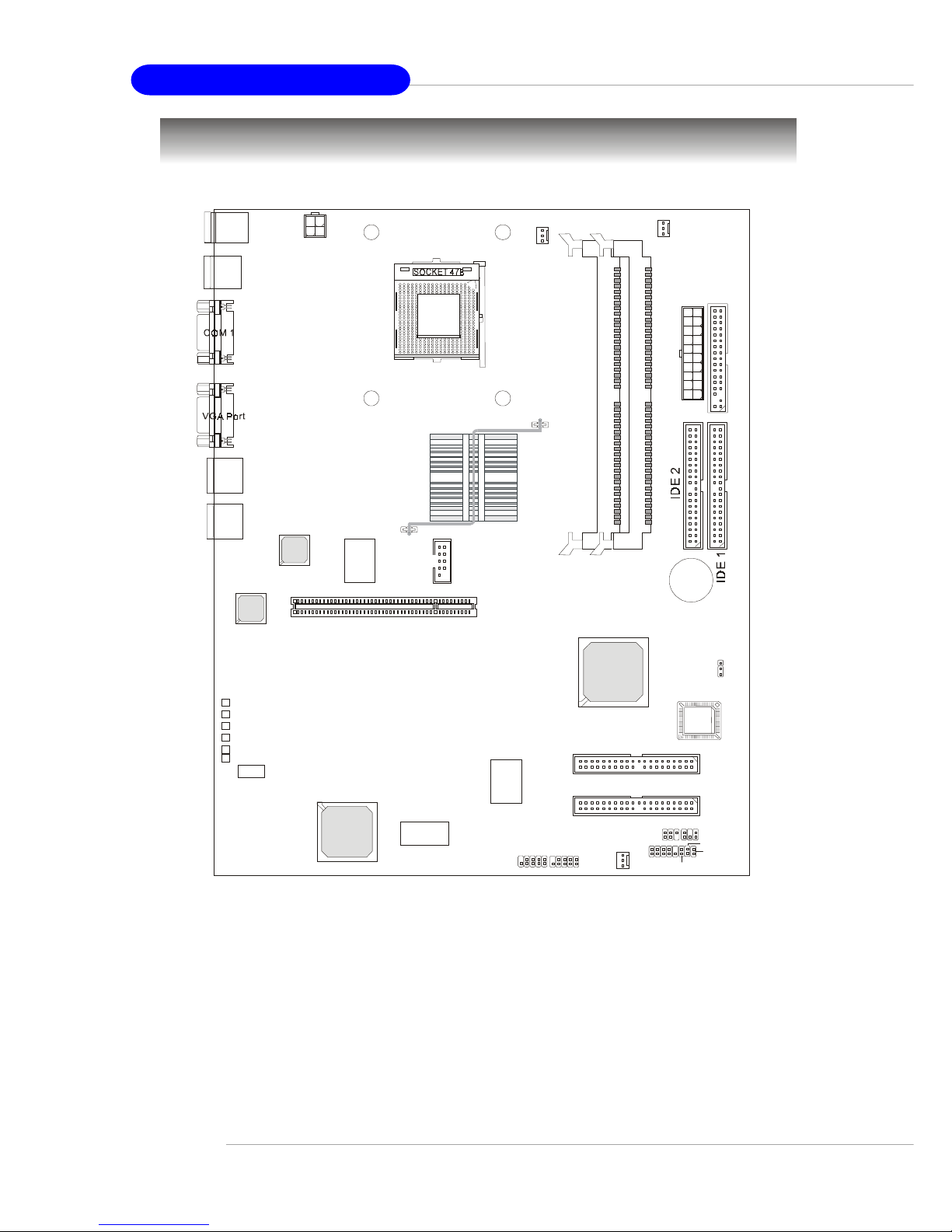
Mainboard Layout
845E Master-LR (MS-9129 v1.X) A TX Mainboard
PSFAN1
CFAN1
+BATT
ICH 4
A
T
X
P
o
w
e
r
S
u
p
p
l
y
JFP1
JLCD1
IR2
JACT2
JACT1
J14
FWH
ATI
RageXL
Intel
LAN Chip
PCI 1
IDE 4
IDE 3
Promise
PDC20276
Winbond
PC87431HM
W
i
n
b
o
n
d
W
8
3
6
2
7
H
F
-
A
W
USB
ports
JPW1
LAN 1
LAN 2
Top : mouse
Bottom: keyboard
JBAT1
LED4
LED5
LED6
LED2
LED3
LED1
JUSB2 JUSB3
COM 2
SFAN1
D
I
M
M
1
D
I
M
M
2
I
n
t
e
l
8
4
5
c
h
i
p
s
e
t
Intel
LAN Chip
Intel
845E
Chipset
F
D
D
1

1-5
Getting Started
MSI Special Features
PC Alert™ III
The PC AlertTM III is a utility you can find in the CD-ROM disk. The
utility is just like your PC doctor that can detect the following PC hardware status during
real time operation:
Ø monitor CPU & system temperatures
Ø monitor fan speed(s)
Ø monitor system voltage
Ø monitor chassis intrusion
If one of the items above is abnormal,
the program main screen will be immediately
shown on the screen, with the abnormal item
highlighted in red. This will continue to be
shown until user disables the warning.
MSI Reminds Y ou...
1. Items shown on PC Alert™ III vary depending on your system
status.
2. The mainboard bound with mBMC chip (Server Management
Features) won’t support PC Alert™ III.
1-6
MS-9211 1U Rackmount Server
D-LED™ (Optional)
The D-LED™ (Diagnostic LED) uses graphic signal display to help users
understand their system. Four LEDs (LED1 ~ LED4) embedded on the mainboard provide up to 16 combinations of signals to debug the system. The 4
LEDs can debug all problems that fail the system, such as VGA, RAM or other
failures. This special feature is very useful for the overclocking users. These
users can use the feature to detect if there are any problems or failures. The
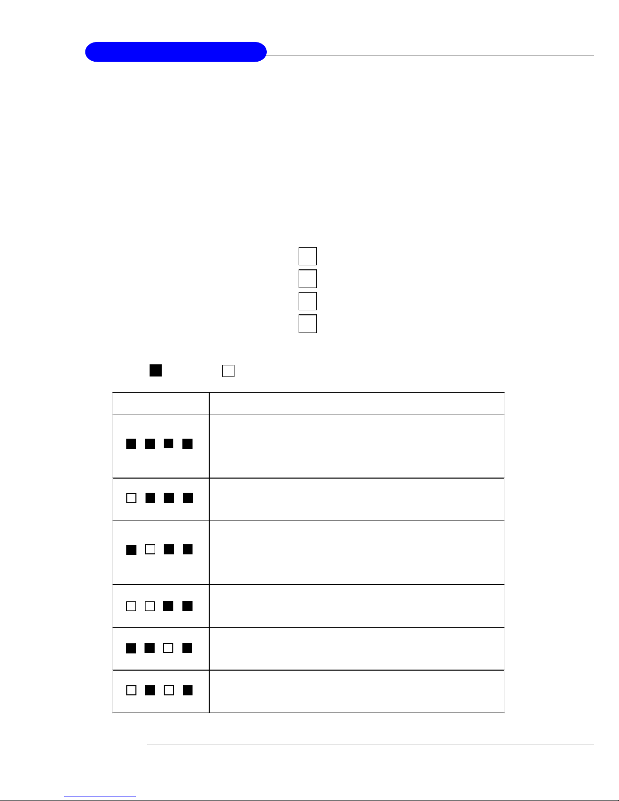
definitions of LED signal combinations are listed below:
D-LED Description
System Power ON
- The D-LED will hang here if the processor is damaged or not installed
properly.
Early Chipset Initialization
Memory Detection Test
- Testing onboard memory size. The D-LED will hang if the memory
module is damaged or not installed properly.
Decompressing BIOS image to RAM for fast booting.
Initializing Keyboard Controller.
Testing VGA BIOS
- This will start writing VGA sign-on message to the screen.
Red
Green
1234
Diagnostic LED
1
2
3
4
1-7
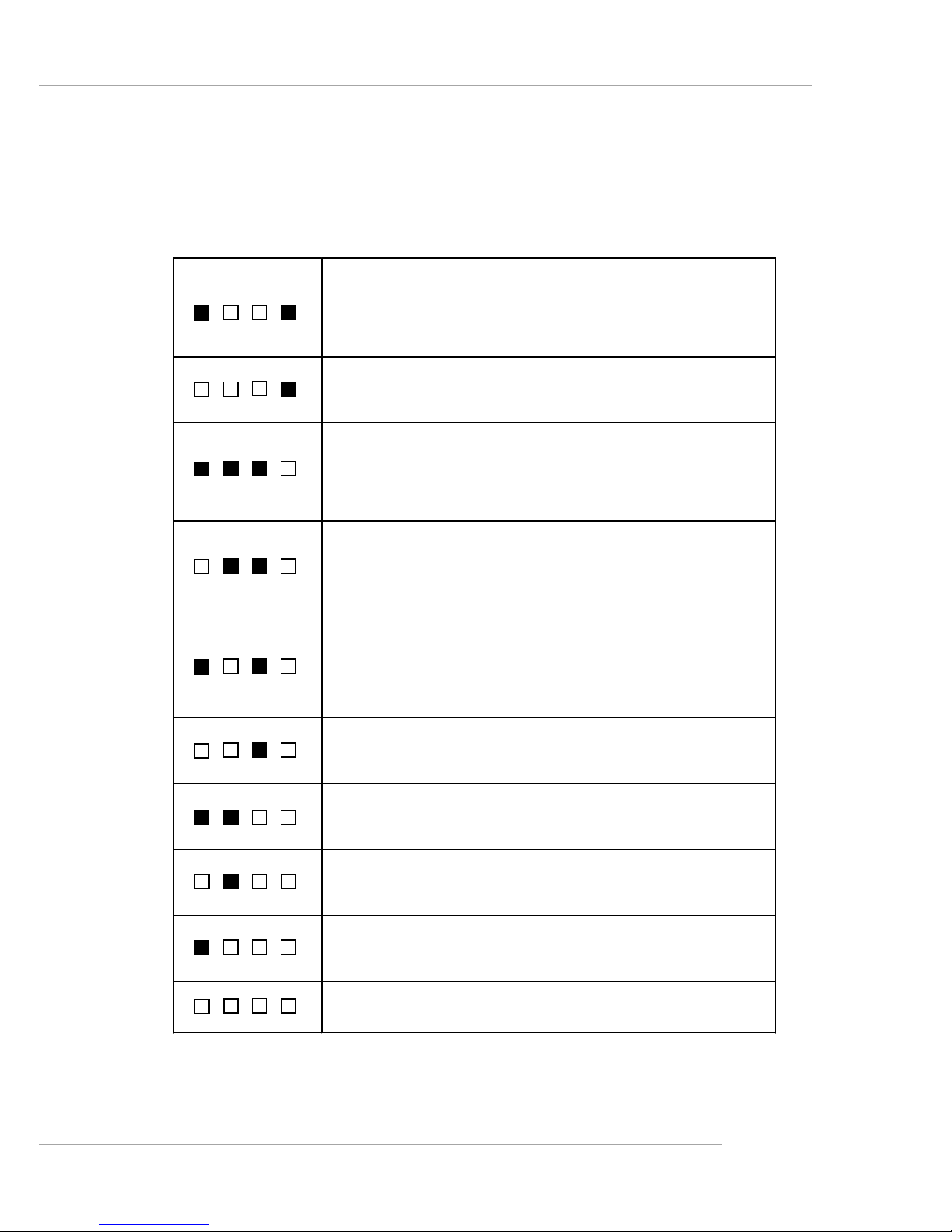
Getting Started
Processor Initialization
- This will show information regarding the processor (like brand name,
system bus, etc…)
Testing RTC (Real Time Clock)
Initializing Video Interface
- This will start detecting CPU clock, checking type of video onboard.
Then, detect and initialize the video adapter.
BIOS Sign On
- This will start showing information about logo, processor brand name,
etc….
Testing Base and Extended Memory
- Testing base memory from 240K to 640K and extended memory
above 1MB using various patterns.
Assign Resources to all ISA.
Initializing Hard Drive Controller
- This will initialize IDE drive and controller.
Initializing Floppy Drive Controller
- This will initializing Floppy Drive and controller.
Boot Attempt
- This will set low st ack and boot via INT 19h.
Operating System Booting
1-8
MS-9211 1U Rackmount Server
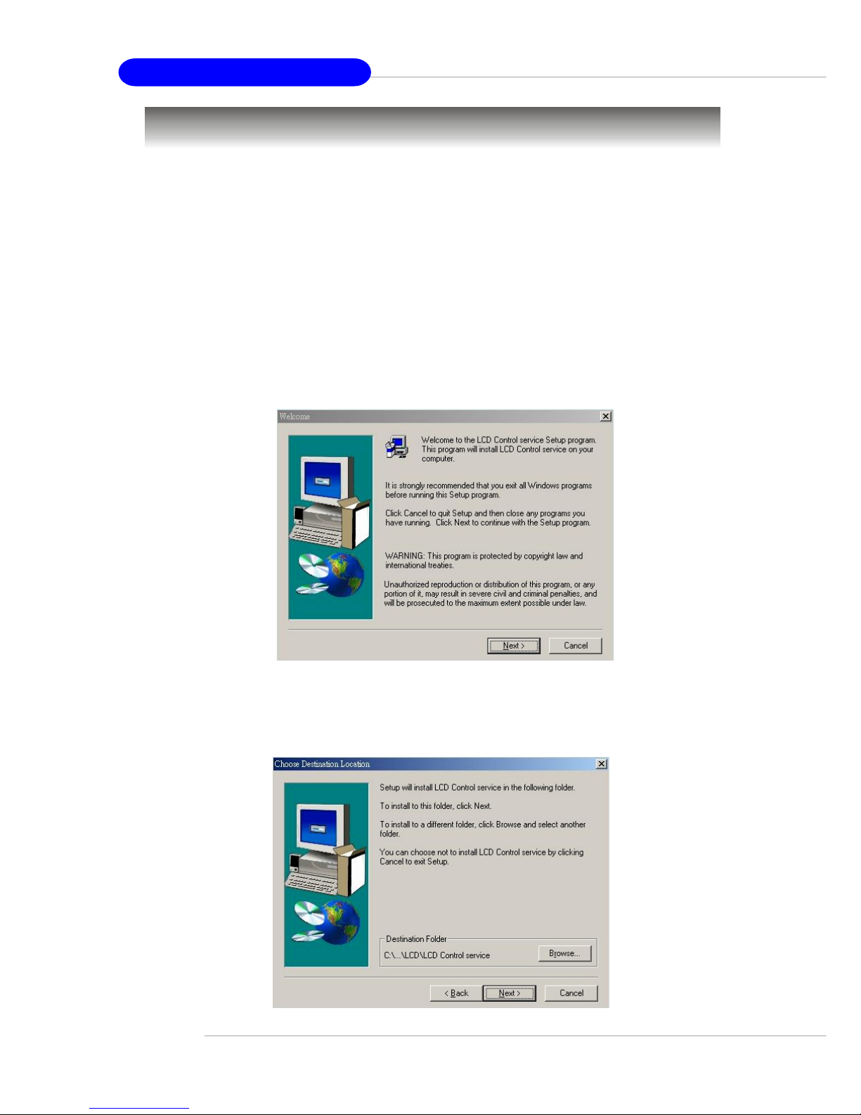
Step 3: T o install the LCD Control Service, click Next to use the default folder
or Browse to install to another designated folder. Click Cancel to exit
the Setup program.
Installing the LCD Control Service
V ersion: V2.2
OS supported: Windows NT 4 with Service Pack 4 or latest version
Windows 2000, W indows XP
Step 1: Insert the installation CD into the CD-ROM drive. Browse to the CD-
ROM drive and double-click the executable file “setup.exe” to start
the Setup program.
Step 2: The screen will show the W elcome dialog box as shown below. Click
Next to continue.
LCD Front Panel Control
1-9
Getting Started
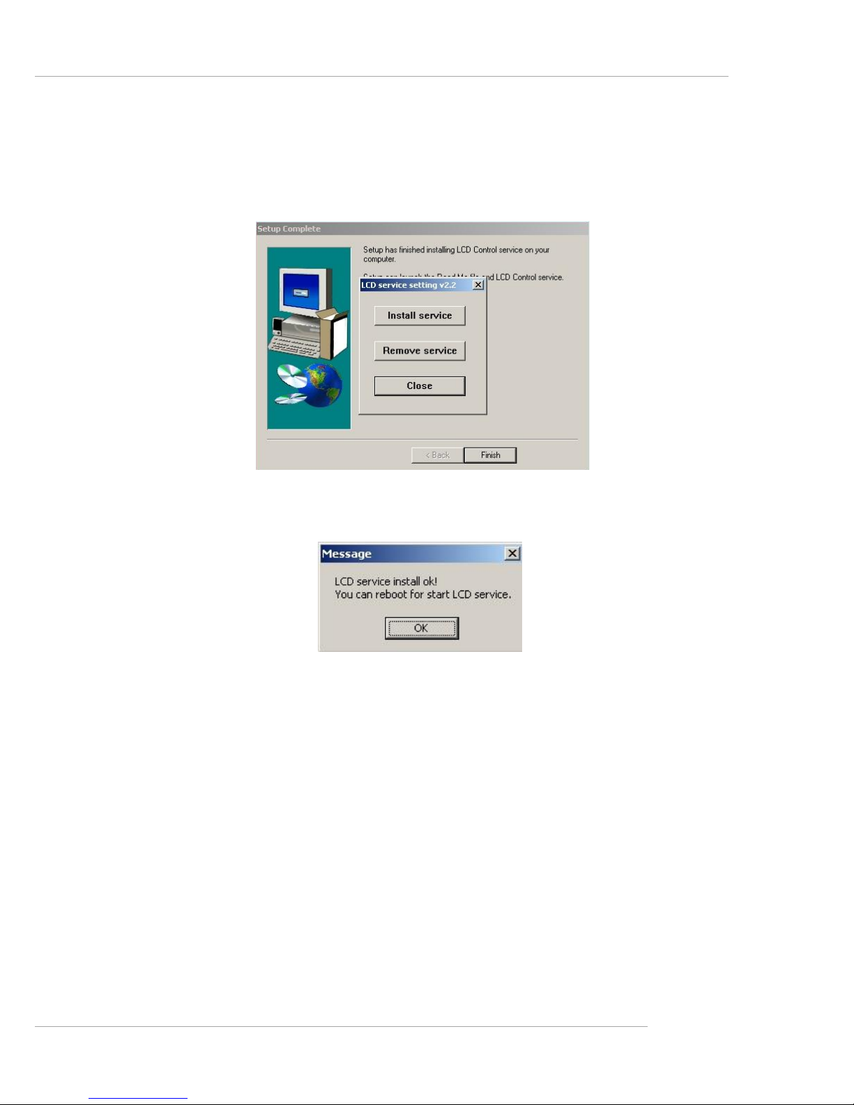
Step 4: Setup has finished installing the LCD Control service on your computer.
Click Install service to enable the LCD Control service.
Step 5: Click OK to continue. You can restart the computer now .
1-10
MS-9211 1U Rackmount Server
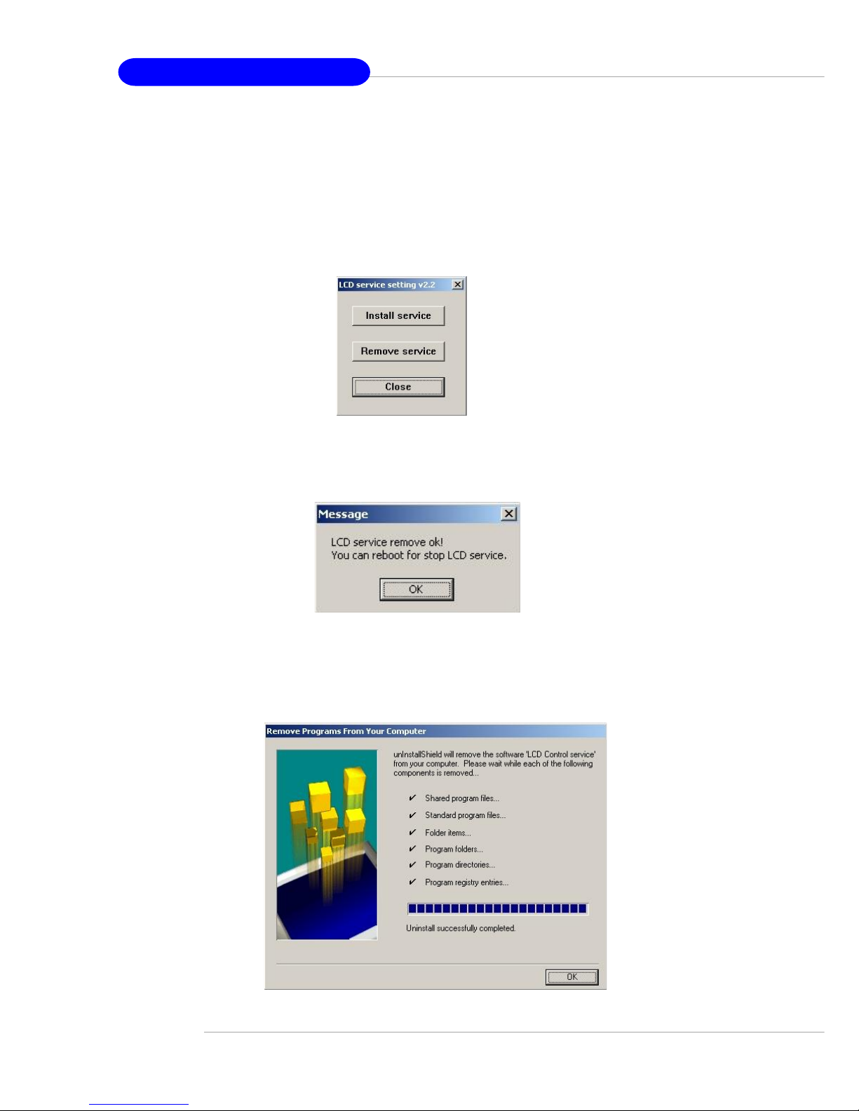
Un-installing the LCD Control Service
Step 1: Click Start, and then point to Programs.
Under Programs, Click LCD Control Panel and the following screen
will pop up. Click Remove service to disable the LCD Control service.
Step 3: Under Control Panel, click Add/Remove Programs. Follow the on-
screen instructions to complete the un-installation process.
Step 2: Click OK to continue.
1-11
Getting Started
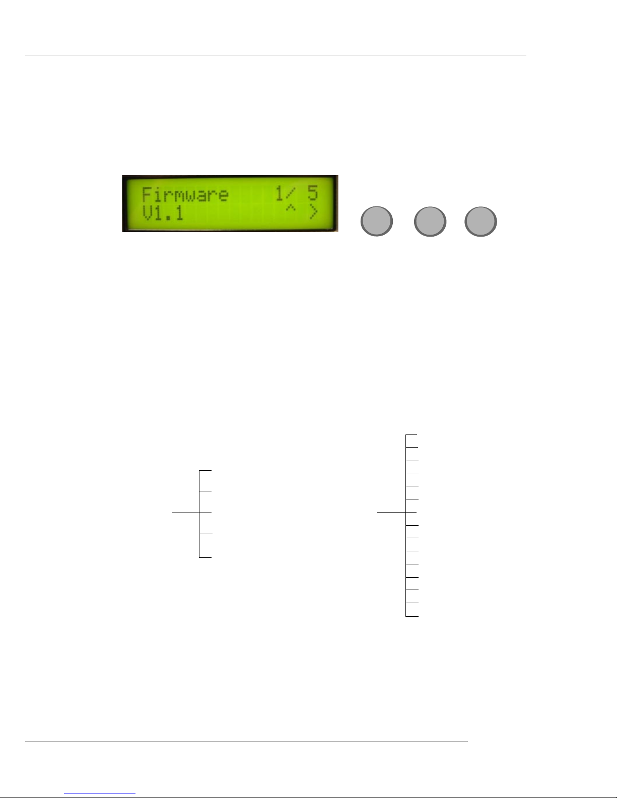
Here shows the LCD Front Panel and its three control buttons.
Up Go to the previous selection.
Enter Execute the command.
Next Go to the next selection.
Up
Enter
Next
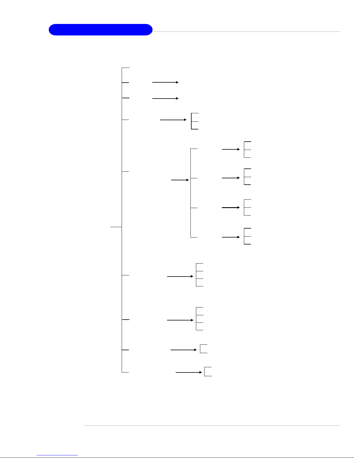
LCD Function Menu
After you have installed the LCD Control Panel Service, you can simply use
the LCD Front Panel Control buttons to get access to the information under
LCD Info, H/W Monitor and System Conf menus.
CPU (temp.)
Chassis (temp.)
System FAN
Power FA N
CPU FAN
V core
I/O Voltage
3.3V
5V
12V
-12V
-5V
5V Standby
Battery
chassis int
H/W Monitor
Build Date
Mode
Firmware
LCD Info
Character
Baud Rate
1-12
MS-9211 1U Rackmount Server
System Conf
Host name
Date
Time
Memory
Hard Disk
Information
LAN1
LAN2
Restart OS
Shutdown OS
Set Date
Set Time
IP
Net Mask
Set IP
Set Net Mask
IP
Net Mask
Set IP
Set Net Mask
Yes
No
Yes
No
Disk C
Disk D
Disk E
Disk F
Size
Usage
Available
Size
Usage
Available
Size
Usage
Available
Size
Usage
Available
Size
Usage
Available

1-13
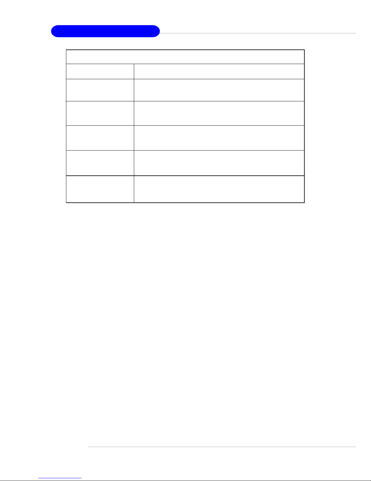
Getting Started
Function Description
LCD Panel v1.1 Show product information and version
Initialize OK
BIOS POST: C1 If the system has memory issues, it will stop at C1.
Msg: Mem Sizing
BIOS POST: C3 If the system has BIOS issues, it will stop at C3.
Msg: BIOS chsum
BIOS POST: 18 If the system has CPU issues, it will stop at 18.
Msg: CPU Init.
BIOS POST: 2B If the system has VGA issues, it will stop at 2B.
Msg: VGA Init.
BIOS POST: 2D It shows information about logo processor brand name.
Msg: Sign-on Msg.
BIOS POST: 52 If the system has memory issues, it will stop at 52.
Msg: Ext. Mem Test
BIOS POST: 75 If the system has IDE issues, it will stop at 75.
Msg: IDE Init.
BIOS POST: 8B If the system has PCI issues, it will stop at 8B.
Msg: PCI ROM Init.
BIOS POST: 94
Msg: disp summary
<Boot to OS> If the system is problem free, it will boot to OS.
Before Boot to OS (Debug Function)
1-14
MS-9211 1U Rackmount Server
Function Description
Firmware 1/5 Show LCD Firmware version
V1.1
Mode 2/5 Show LCD working mode
Communication
Build date 3/5 Show LCD Firmware build date
2002/03/25
Baud Rate 4/5 Show LCD communication speed with COM port
9600 For PC and LCD link
Character 5/5 Show LCD characters
16X2
LCD Info

1-15
Getting Started
Function Description
CPU 1/15 Show CPU temperature information
42C
Chassis 2/15 Show chassis temperature information
28C
System FAN 3/15 Show System FAN speed information
0 RPM
Power FAN 4/15 Show Power FAN speed information
4219 RPM
CPU FAN 5/15 Show CPU FAN speed information
0 RPM
V core 6/15 Show V core voltage information
1.46V
I/O Voltage 7/15 Show I/O voltage information
1.08V
3.3V 8/15 Show 3.3V voltage information
3.26V
+5V 9/15 Show +5V voltage information
5.07V
+12V 10/15 Show +12V voltage information
12.02V
-12V 11/15 Show -12V voltage information
-11.98V
-5V 12/15 Show -5V voltage information
-5.09V
5V Standby 13/15 Show 5V voltage information
4.94V
Battery 14/15 Show battery information
3.04V
Chassis int 15/15 Show chassis intrusion detect information
OFF
H/W Monitor

1-16
MS-9211 1U Rackmount Server
Function Description
Host name 1/9 Show system’s host name
Date 2/9 Set Date 1/1 Show the date and allow to set the date
2002.8.21
Time 3/9 Set Time 1.1 Show the time and allow to set the time
13:24:50
Memory 4/9 Size 1/3 Show memory’s size
511MB
Usage 2/3 Unable to show used memory size
153MB
A vailable 3/3 Unable to show available memory size
358MB
Hard Disk 5/9 It can detect 4 disks on this system.
Information
Disk C 1/4 Size 1/3 Show this partition’s size
3698MB 3698MB
Usage 2/3 Unable to show the used size
1485MB
A vailable 3/3 Unable to show the available size
2213MB
Disk D 2/4 Size 1/3 Show this partition’s size
15393MB 15393MB
Usage 2/3 Unable to show the used size
494MB
A vailable 3/3 Unable to show the available size
14899MB
Disk E 3/4 Size 1/3 Show this partition’s size
0MB 0MB
Usage 2/3 Unable to show the used size
0MB
System Conf

1-17
Getting Started
Function Description
A vailable 3/3 Unable to show the available size
0MB
Disk F 4/4 Size 1/3 Show this partition’s size
0MB 0MB
Usage 2/3 Unable to show the used size
0MB
A vailable 3/3 Unable to show the available size
0MB
LAN1 6/9 IP 1/4 Show the system IP information
100.100.100.101 100.100.100.101
Netmask 2/4 Show the system Net Mask information
255.255.255.0
Set IP Allow users to set the system’s IP
000.000.000.000
Setmask Allow users to set the system’s Net Mask
000.000.000.000
LAN2 7/9 IP 1/4 Show the system IP information
100.100.100.101 100.100.100.101
Netmask 2/4 Show the system Net Mask information
255.255.255.0
Set IP Allow users to set the system’s IP
000.000.000.000
Setmask Allow users to set the system’s Net Mask
000.000.000.000
Restart 8/9 Yes/No Restart your Windows OS
Restart OS
Shutdown 9/9 Yes/No Shut down your Windows OS
Shutdown OS
System Conf (continued)
1-18
MS-9211 1U Rackmount Server
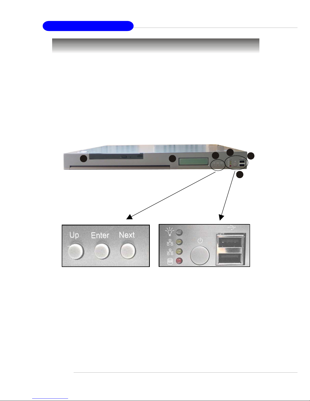
Front View
This section shows the configuration of the MS-9211 from different
angles, and the connectors and buttons on the front and back panel.
1. LCD Front Panel
2. Slim CD-ROM Drive (optional)
3. LED Indicators
4. Power Button
5. USB Ports
6. LCD Control Buttons
5
after enlargement
1
2
3
4
6
System Configuration
1-19
Getting Started
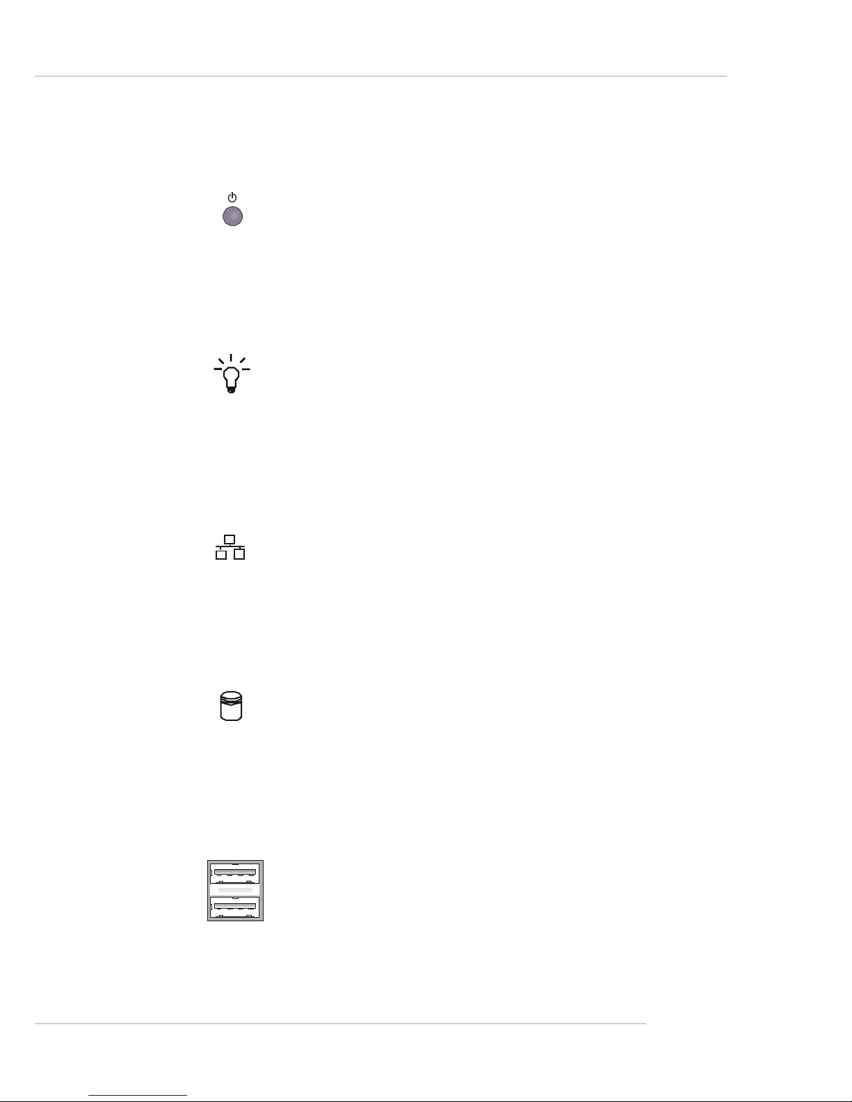
USB Ports
With the four USB port (2 in the front, 2 in the rear) design, you can easily add
new capacities to your PC like never before.
Power Button
This main power button is used to turn on or off the system.
Power Indicator
This indicator shows the power status of the system. It glows when the
main power is turned on.
LAN Status Indicators
These two LED indicators flash to show the activity status on LAN1 and
LAN2.
Hard Disk Drive In-use Indicator
This indicator shows the activity status of the hard disk drive. It flashes
when the system is accessing data on the hard disk.
1-20
MS-9211 1U Rackmount Server
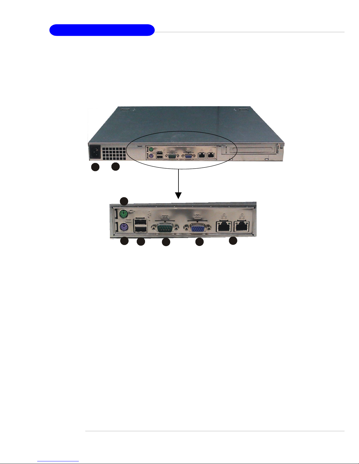
Rear View
1. Power Connector
2. Heat Dissipation Opening
3. PS/2 Keyboard Connector
4. PS/2 Mouse Connector
5. Serial Port COM A
6. VGA Port
7. LAN Jacks 1 & 2
8. USB Ports 1 & 2
1
2
after enlargement
3
4
5
6
7
8
1-21
Getting Started
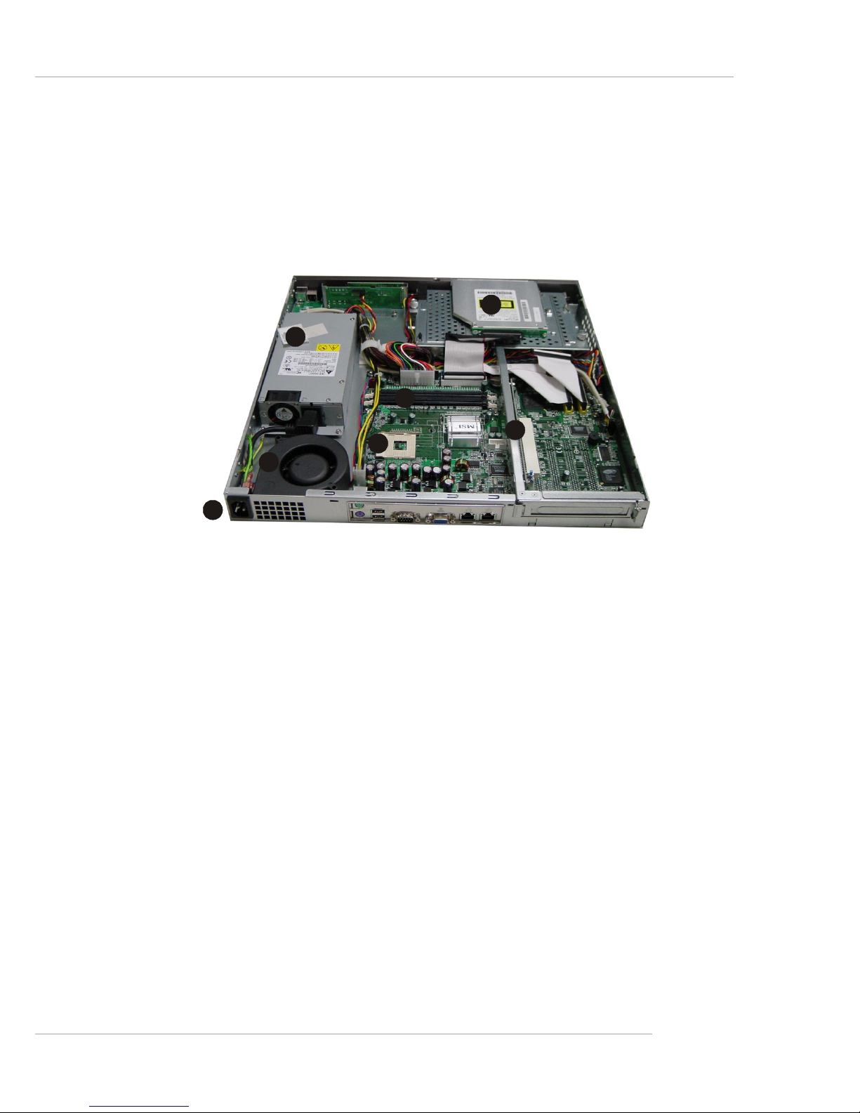
T op View
1. ATX Power Supply
2. Slim CD-ROM Drive (optional)
3. DIMM Slots
4. Riser Card Bracket
5. CPU Socket
6. Blower
7. AC Power Connector
7
6
1
2
3
5
4
1-22
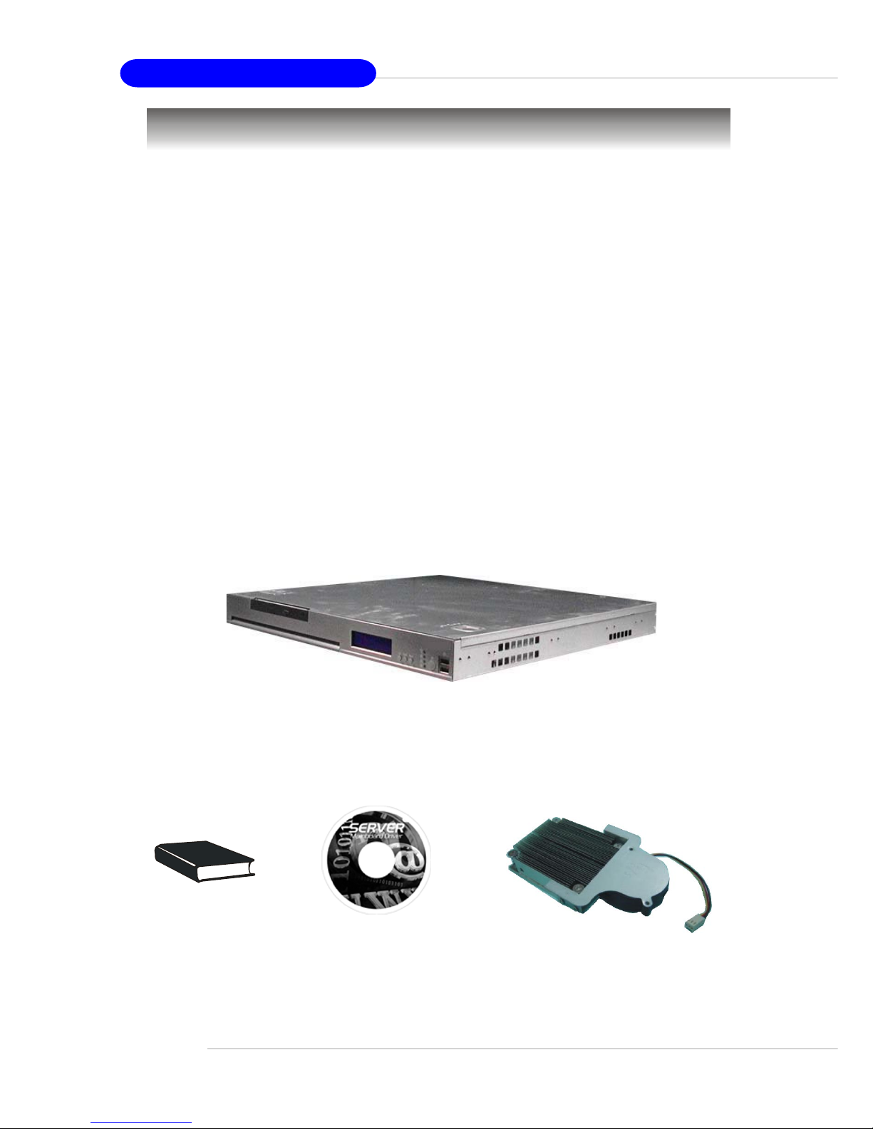
MS-9211 1U Rackmount Server
MS-921 1 1U Rackmount Server
(includes a mainboard, a A TX Power
Supply and a Fan Duct )
Unpack the package and check if all items listed below are present. If
any item contained in the package is damaged or missing, please contact your
local dealer for replacement. In addition, keep the box and packing materials for
possible future use.
Your MS-9211 1U Rackmount Server Barebone package should contain
the following items:
User’s Guide Server Driver CD
Heat Sink
Packing Checklist
 Loading...