

Page 1
FCC-B Radio Frequency Interference Statement
This equipment has been tested and found to comply with the lim its for a class B digital devic e, pur su ant to
part 15 of the FCC rules. These limits are designed t o provi de re aso na bl e pr ot ectio n against harmful
interference when the equipment is operated in a commercial environment. This equipment generates, uses
and can radiate radio frequency energy and, if not installed and used in accordance with the instruction
manual, may cause harmful interference to radio communications. Operation of this equipment in a
residential area is likely to cause harmful interference, in which case the user will be required to correct the
interference at his own e xpens e.
Notice 1
The changes or modifications not expressly approved by the party responsible for compliance could void the
user’s authority to operate the equipment.
Notice 2
Shielded interface cables and A.C. power cord, if any, must be used in order to comply with the emission
limits.
VOIR LA NOTICE D’NSTALLATION AVANT DE RACCORDER AU RESEAU.
Micro-Star International
MS-7154
This device complies with Part 15 of the FCC Rules. Operation is subject to the following two conditions:
(1) this device may not cause harmful interference, and
(2) this device must accept any interference received, including interference that may cause undesired
operation
G52-M7154X1
i
Page 2

Copyright Notice
The material in this document is the intellectual property of MICRO-STAR INTERNATIONAL. We take every
care in the preparation of this document, but no guarantee is given as to the correctness of its contents. Our
products are under continual improvement and we reserve the right to make changes without notice.
Trademarks
All trademarks are the properties of their respective owners.
AMD, Athlon™ Athlon™XP, Thoroughbred™ and Duron™ are registered trademarks of AMD Corporation.
Intel® and Pentium® ar e regi st er ed tra dem ark s of Intel Cor po ration.
PS/2 and OS® 2 are registered trademarks of International Business Machines Corporation.
Microsoft® is a registered trademark of Microsoft Corporation. Windows® 98/2000/NT/XP are registered
trademarks of Microsoft Corporation.
NVIDIA, the NVIDIA logo, DualNet, and nForce are registered trademarks or trademarks of NVIDIA
Corporation in the United States and/or other countries.
Netware® is a registered trademark of Novell, Inc.
Award® is a registered trademark of Phoenix Technologies Ltd.
AMI® is a registered trademark of American Megatrends Inc.
Kensington and MicroSaver are registered trademarks of the Kensington Te chnology Group.
PCMCIA and CardBus are registered trademarks of the Personal Computer Memory Card International
Association.
Revision History
Revision Revision History Date
V1.0 First release December 2004
ii
Page 3

Safety Instructions
1. Always read the safety instructions carefully.
2. Keep this User Manual for futur e ref ere nce.
3. Keep this equipment a way from humidi t y.
4. Lay this equipment on a reliable flat surface before setting it up.
5. The openings on the enclosure are for air convection hence protects the equipment from overheating.
Do not cover the openings.
6. Make sure the voltage of the power source and adjust properly 110/220V before connecting the
equipment to the power inlet.
7. Place the power cord such a way that people can not step on it. Do not place anything over the power
cord.
8. Always Unplug the Power Cord before inserting any add-on card or module.
9. All cautions and warnings on the equipment should be noted.
10. Never pour any liquid into the opening that could damage or cause electrical shock.
11. If any of the following situations arises, get the equipment checked by a service personnel:
- The power cord or plug is damaged .
- Liquid has penetrated into the equipment.
- The equipment has been expose d to m oistur e.
- The equipment does not work well or you can not get it work according to the User’ Manual.
- The equipment has dropped and damaged.
- The equipment has obvious sign of breakage.
12. Do not leave this equipment in an environment unconditioned, storage temperature above 60° C (140°F),
it may damage the equipment.
iii
Page 4

Table of Contents
ENGLISH..................................................................1
简体中文...................................................................17
iv
Page 5

1
BATT+ICH4
D
D
R 2
D
D
R 1
JCD1
JFP2
JFP1
JBAT1
JPUSB1
JUSB1
JAUD1
JCI1
PWR1
SYS_FAN1
CPUFAN1
PCI Slot 2
PCI Slot 1
PCI Slot 3
PCI Slot 4
I
D
E
1
I
DE
2
Top: Parallel Port
Bottom:
COM A
Top: Mouse
Bottom: Keyboard
Top: LAN Jack
Bottom: USB
Ports
USB
Ports
Codec
JPW1
T: Line-In
M:
B: Mic
Line-Out
FDD 1
Winbond
W83627THF
Broadcom
BCM4401KQL
AGP Slot
Intel 845PE
BIOS
Introduction
Thank you for purchasing 845PE-V2 Series (MS-7154) v1.X Micro ATX mainboard. The 845PE-V2
Series is based on Intel ® 845PE & Intel ® ICH4 chipsets and provides 6 USB 2.0 ports for high-speed
data transmission. With all these special designs, the 845PE-V2 Series delivers a high performance
and professional desktop platform solution.
Layout
Page 6

2
Specifications
CPU
l Socket 478 for P4 processors (Northwood/Prescott) at 400MHz/533MHz/800MHz (800MHz for
overclocking)
l Supports up to 3.4GHz or faster.
(For the latest information about CPU, please visit
http://www.msi.com.tw/program/products/mainboard/mbd/pro_mbd_cpu_support.php )
Chipset
l Intel ® 845PE
- Supports FSB 400MHz/533MHz/800MHz (800MHz for overclocking)
- Supports DDR266/333/400 (DDR400 for overclocking) technology.
l Intel ® ICH4
- AC97 Controller Integrated.
- 6 ports Hi-Speed USB 2.0 controller, 480Mb/sec.
- Supports both ACPI and legacy APM power management.
- Legacy free support.
Main Memory
l Supports 2 memory banks using two 184-pin unbuffered DDR 266/333/400 (DDR400 for
overclocking) DIMMs.
l Supports up to 2GB memory size without ECC.
(For the updated supporting memory modules, please visit
http://www.msi.com.tw/program/products/mainboard/mbd/pro_mbd_trp_list.php )
Slots
l One AGP (Accelerated Graphics Port) slot that supports AGP 2.0 4X/2X.
l Four PCI 2.2 32-bit Master PCI Bus slots (support 3.3V/5V PCI bus interface).
On-Board IDE
l Dual IDE controllers integrated in Intel ® ICH4.
l Supports Bus Master, Ultra DMA 33/66/100 operation modes.
l Can connect up to four IDE devices.
On-Board Peripherals
l On-Board Peripherals includes:
Page 7

3
- 1 floppy port supports 1 FDD with 360K, 720K, 1.2M, 1.44M and 2.88 Mbytes.
- 1 serial port (COMA)
- 1 parallel port supports SPP/EPP/ECP mode
- 6 USB 2.0/1.1 ports (Rear * 4 / Front * 2)
- 1 Line-In/Line-Out/Mic-In port
- 1 RJ-45 LAN connector
Audio
l AC97 link controller integrated in Intel ® ICH4.
l 6 channels S/W audio codec AD1888 codec
- Compliance with AC97 2.2 Spec
- Meets PC2001 audio performance requirement
LAN
l Broadcom 4401 PCI2.2 LAN
- Supports 10Mb/s and 100Mb/s auto-negotiation operations.
- Compliance with PCI 2.2 and PC99 standard.
BIOS
l 2MB Award BIOS with PNP BIOS, ACPI, SMBIOS 2.3, Green and Boot Block.
l Provides DMI 2.0, WFM 2.0, WOL, chassis intrusion, and SMBus for system management.
Dimension
l ATX Form Factor: 30.5 cm (L) x 17.5 cm (W).
Mounting
l 6 mounting holes.
Page 8
4
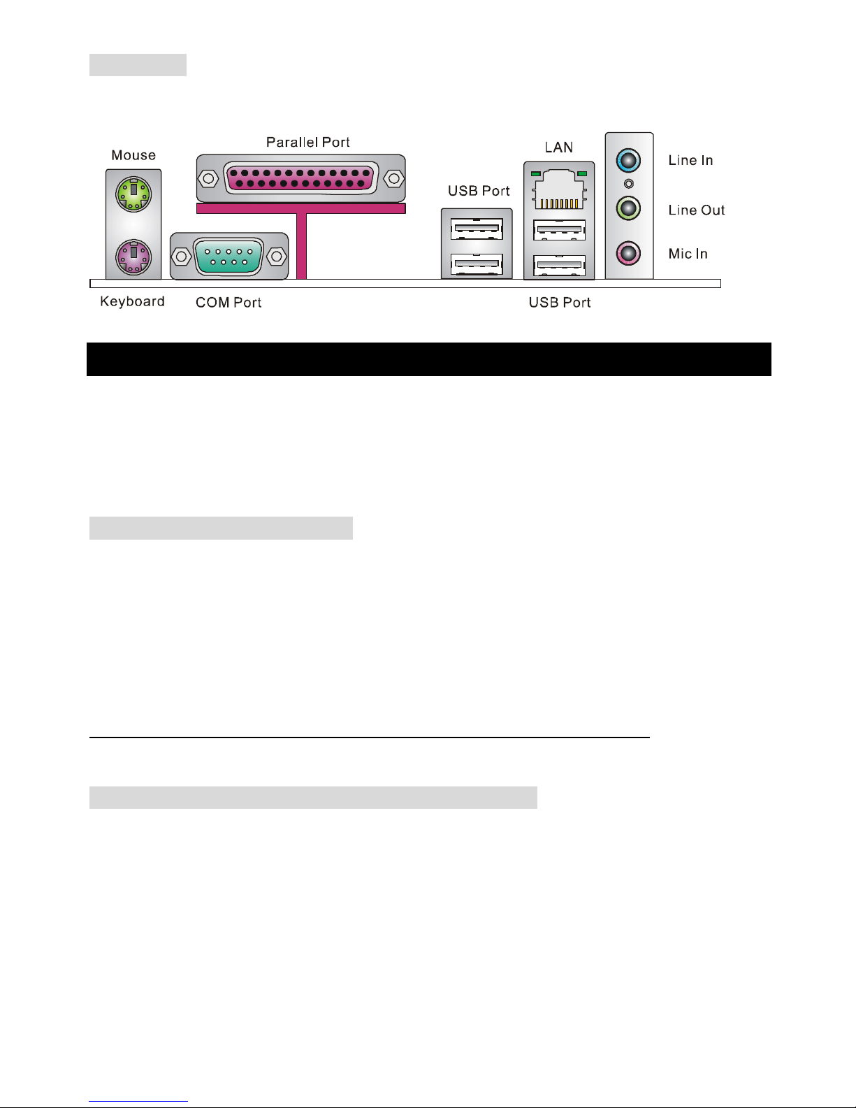
Rear Panel
The back panel provides the following connectors:
Hardware Setup
This chapter tells you how to install the CPU, memory modules, and expansion cards, as well as how to
setup the jumpers on the mainboard. It also provides the instructions on connecting the peripheral
devices, such as the mouse, keyboard, etc. While doing the installation, be careful in holding the
components and follow the installation procedures.
Central Processing Unit: CPU
The mainboard supports Intel Pentium 4 Northwood & Prescott Celeron processor in the 478 pin
package. The mainboard uses a CPU socket called PGA478 for easy CPU installation. When you are
installing the CPU, make sure the CPU has a heat sink and a cooling fan attached on the top to prevent
overheating. If you do not find the heat sink and cooling fan, contact your dealer to purchase and install
them before turning on the computer. (For the latest information about CPU, please visit
http://www.msi.com.tw/program/products/mainboard/mbd/pro_mbd_cpu_support.php )
Example of CPU Core Speed Derivation Procedure
If CPU Clock = 133MHz
Core/Bus ratio = 23
then CPU core speed = Host Clock x Core/Bus ratio
= 133MHz x 23
= 3.06 GHz
Page 9

5
Memory Speed/CPU FSB Support Matrix
Memory
FSB
DDR 266 DDR 333 DDR 400*
400 MHz OK OK OK
533 MHz OK OK OK
800 MHz* OK OK OK
* For overclocking only.
MSI Reminds You...
Overheating…
Overheating will seriously damage the CPU and system, always make sure the cooling fan can work
properly to protect the CPU from overheating.
Replacing the CPU…
While replacing the CPU, always turn off the ATX power supply or unplug the power supply’s power
cord from grounded outlet first to ensure the safety of CPU.
CPU Installation Procedures for Socket 478
1. Please turn off the power and unplug the power cord before installing the CPU.
2. Pull the lever sideways away from the socket. Make sure to raise the lever up to a 90-degree
angle.
3. Look for the gold arrow. The gold arrow should point towards the lever pivot. The CPU can only
fit in the correct orientation.
4. If the CPU is correctly installed, the pins should be completely embedded into the socket and
can not be seen. Please note that any violation of the correct installation procedures may cause
permanent damages to your mainboard.
5. Press the CPU down firmly into the socket and close the lever. As the CPU is likely to move
while the lever is being closed, always close the lever with your fingers pressing tightly on top of
the CPU to make sure the CPU is properly and completely embedded into the socket.
Page 10

6
Installing the CPU Fan
As processor technology pushes to faster speeds and higher performance, thermal management
becomes increasingly important. To dissipate heat, you need to attach the CPU cooling fan and
heatsink on top of the CPU. Follow the instructions below to install the Heatsink/Fan:
1. Locate the CPU and its retention mechanism on the motherboard.
2. Position the heatsink onto the retention mechanism.
3. Mount the fan on top of the heatsink. Press down the fan until its four clips get wedged in the
holes of the retention mechanism.
4. Press the two levers down to fasten the fan. Each lever can be pressed down in only ONE
direction.
5. Connect the fan power cable from the mounted fan to the 3-pin fan power connector on the
board.
Memory
The mainboard provides two 184-pin unbuffered DDR266/DDR333/DDR400 SDRAM, and supports the
memory size up to 2GB. To operate properly, at least one DIMM module must be installed. (For the
updated supporting memory modules, please visit
http://www.msi.com.tw/program/products/mainboard/mbd/pro_mbd_trp_list.php )
Install at least one DIMM module on the slots. Memory modules can be installed on the slots in any
order. You can install either single- or double-sided modules to meet your own needs.
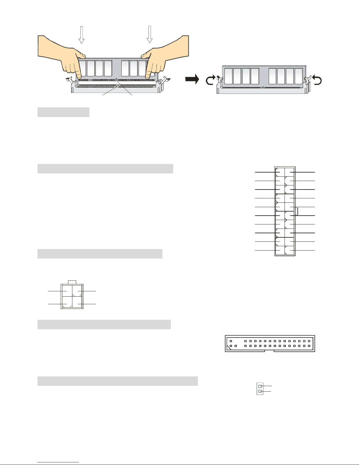
Installing DDR Modules
1. The DDR DIMM has only one notch on the center of module. The module will only fit in the right
orientation.
2. Insert the DIMM memory module vertically into the DIMM slot. Then push it in until the golden
finger on the memory module is deeply inserted in the socket.
3. The plastic clip at each side of the DIMM slot will automatically close.
Page 11
7
NotchVolt
Power Supply
The mainboard supports ATX power supply for the power system. Before inserting the power supply
connector, always make sure that all components are installed properly to ensure that no damage will
be caused. A 300W or above power supply is suggested.
ATX 20-Pin Power Connector: PWR1
This connector allows you to connect to an ATX power supply. To
connect to the ATX power supply, make sure the plug of the power
supply is inserted in the proper orientation and the pins are aligned.
Then push down the power supply firmly into the connector.
ATX 12V Power Connector: JPW1
This 12V power connector is used to provide power to the CPU.
132
4
GND
GND
12V
12V
Floppy Disk Drive Connector: FDD1
The mainboard provides a standard floppy disk drive connector
that supports 360K, 720K, 1.2M, 1.44M and 2.88M floppy disk
types.
Chassis Intrusion Switch Connector: JCI1
This connector is connected to 2-pin connector chassis switch. If the
Chassis is open, the switch will be short. The system will record this status. To clear the warning, you
3.3V
-12V
GND
GND
PW_OK
-5V
5V_SB
5V
12V
PS_ON
10
20
11
1
GND
GND
5V
GND
GND
GND
5V
5V
3.3V
3.3V
2
1
GND
CINTRO
Page 12

8
must enter the BIOS setting and clear the status.
CD-In Connector: JCD1
The connector is for CD-ROM audio connector.
Fan Power Connectors: CPUFAN1/SYS_FAN1
The CPUFAN1 (processor fan) and SYS_FAN1 (system fan) support system
cooling fan with +12V. They support three-pin head connector. When connecting
the wire to the connectors, always take note that the red wire is the positive and
should be connected to the +12V, the black wire is Ground and should be
connected to GND. If the mainboard has a System Hardware Monitor chipset on-board, you must use a
specially designed fan with speed sensor to take advantage of the CPU fan control.
MSI Reminds You...
1. Always consult the vendors for proper CPU cooling fan.
2. CPUFAN1 supports the fan control. You can install the PC Alert utility that will automatically control
the CPU fan speed according to the actual CPU temperature.
IDE Connectors: IDE1 & IDE2
The mainboard has a 32-bit Enhanced PCI IDE and Ultra DMA 33/66/100/133 controller that
provides PIO mode 0~4, Bus Master, and Ultra DMA 33/66/100/133 function. You can
connect up to four hard disk drives, CD-ROM, 120MB Floppy and other devices.
The first hard drive should always be connected to IDE1. IDE1 can connect a Master and a
Slave drive. You must configure second hard drive to Slave mode by setting the jumper
accordingly. IDE2 can also connect a Master and a Slave drive.
MSI Reminds You...
If you install two hard disks on cable, you must configure the second drive to Slave mode by setting its
jumper. Refer to the hard disk documentation supplied by hard disk vendors for jumper setting
instructions.
GND
L
R
Page 13

9
Front Panel Connectors: JFP1 & JFP2
The mainboard provides two front panel connectors for electrical
connection to the front panel switches and LEDs. JFP1 is compliant
with Intel Front Panel I/O Connectivity Design Guide.
Front Panel Audio Connector: JAUD1
The JAUD1 front panel audio connector allows you to connect to the
front panel audio and is compliant with Intel ® Front Panel I/O
Connectivity Design Guide.
MSI Reminds You...
If you do not want to connect to the front audio header, pins 5 & 6, 9 & 10 have to be jumpered in order
to have signal output directed to the rear audio ports. Otherwise, the Line-Out connector on the back
panel will not function.
1
2
9
10
Front USB Connector: JUSB1
The mainboard provides one standard USB 2.0 pin header JUSB1. USB
2.0 technology increases data transfer rate up to a maximum throughput
of 480Mbps, which is 40 times faster than USB 1.1, and is ideal for
connecting high-speed USB interface peripherals such as USB HDD, digital cameras, MP3 players,
printers, modems and the like.
MSI Reminds You...
Please note that the pins of VCC & GND must be connected correctly, or it may cause some damage
Keyboard/Mouse Voltage Jumper: JPUSB1
This jumper is used for setting the voltage of the keyboard/mouse. The default setting is VCC5 (1~2).
VCC5 5V Standby
Page 14

10
Clear CMOS Jumper: JBAT1
There is a CMOS RAM on board that has a power supply from external battery to keep the data of
system configuration. With the CMOS RAM, the system can automatically boot OS every time it is
turned on. If you want to clear the system configuration, use the JBAT1 (Clear CMOS Jumper) to clear
data. Follow the instructions below to clear the data:
1 1
3
Keep Data Clear Data
1
3
MSI Reminds You...
You can clear CMOS by shorting 2-3 pin while the system is off. Then return to 1-2 pin position. Avoid
clearing the CMOS while the system is on; it will damage the mainboard.
AGP (Accelerated Graphics Port) Slot
The AGP slot allows you to insert the AGP graphics card. AGP is an interface specification designed for
the throughput demands of 3D graphics. It introduces a 66MHz, 32-bit channel for the graphics
controller to directly access main memory. The mainboard supports 2x/4x 1.5V AGP card.
PCI (Peripheral Component Interconnect) Slots
The PCI slots allow you to insert the expansion cards to meet your needs. When adding or removing
expansion cards, make sure that you unplug the power supply first. Meanwhile, read the documentation
for the expansion card to make any necessary hardware or software settings for the expansion card,
such as jumpers, switches or BIOS configuration.
Page 15

11
PCI Interrupt Request Routing
The IRQ, abbreviation of interrupt request line and pronounced I-R-Q, are hardware lines over which
devices can send interrupt signals to the microprocessor. The PCI IRQ pins are typically connected to
the PCI bus INT A# ~ INT D# pins as follows:
Order1 Order2 Order3 Order4
PCI Slot 1 INT B# INT C# INT D# INT A#
PCI Slot 2 INT C# INT D# INT A# INT B#
PCI Slot 3 INT D# INT A# INT B# INT C#
PCI Slot 4 INT B# INT C# INT D# INT A#
Page 16
12
BIOS Setup
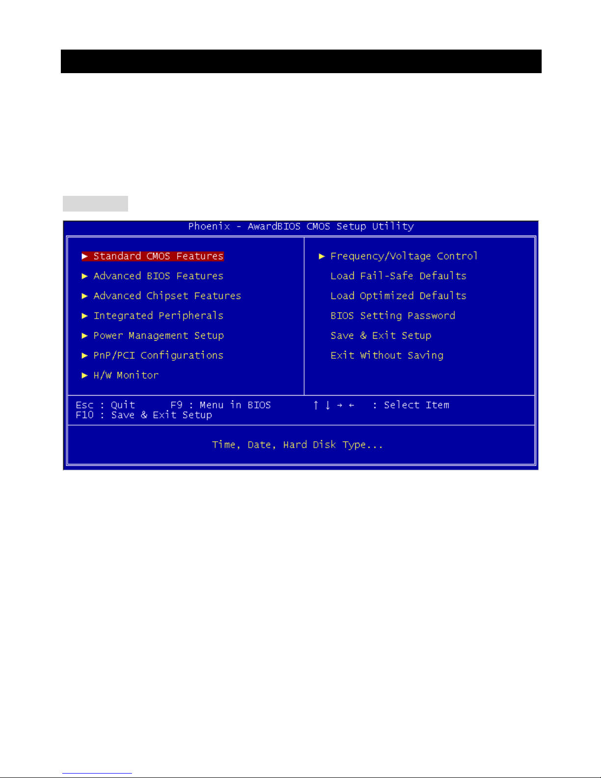
Power on the computer and the system will start POST (Power On Self Test) process. When the
message below appears on the screen, press <DEL> key to enter Setup.
DEL: Setup
If the message disappears before you respond and you still wish to enter Setup, restart the system by
turning it OFF and On or pressing the RESET button. You may also restart the system by
simultaneously pressing <Ctrl>, <Alt>, and <Delete> keys.
Main Page
Standard CMOS Features
Use this menu for basic system configurations, such as time, date etc.
Advanced BIOS Features
Use this menu to setup the items of Award special enhanced features.
Advanced Chipset Features
Use this menu to change the values in the chipset registers and optimize your system performance.
Integrated Peripherals
Use this menu to specify your settings for integrated peripherals.
Power Management Setup
Use this menu to specify your settings for power management.
PNP/PCI Configurations
This entry appears if your system supports PnP/PCI.
H/W Monitor
This entry shows your hardware & PC health status.
Page 17

13
Frequency/Voltage Control
Use this menu to specify your settings for frequency/voltage control.
Load Fail-Safe Defaults
Use this menu to load the BIOS values for the best system performance, but the system stability may
be affected.
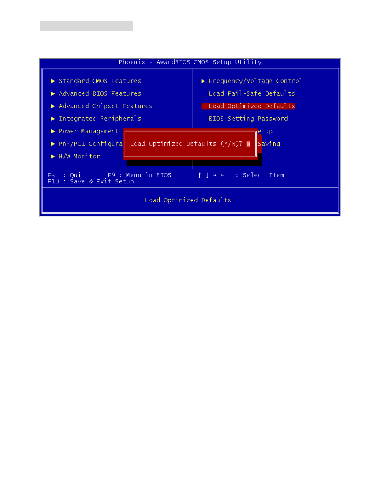
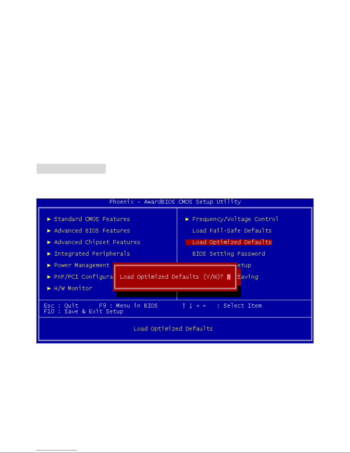
Load Optimized Defaults
Use this menu to load the default values set by the mainboard manufacturer specifically for optimal
performance of the mainboard.
BIOS Setting Password
Use this menu to set BIOS setting Password.
Save & Exit Setup
Save changes to CMOS and exit setup.
Exit Without Saving
Abandon all changes and exit setup.
Page 18

14
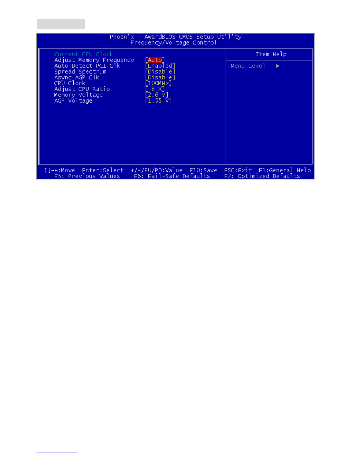
Frequency/Voltage Control
Current CPU Clock
It shows the current clock of CPU. Read-only.
Adjust Memory Frequency
When it is set to [Manual] in High Performance Mode, user can place an artificial memory clock limit on
the system. Please note that memory is prevented from running faster than this frequency. Setting
options: [PC100], [PC133], [Auto].
Auto Detect PCI Clk
This item is used to auto detect the PCI slots. When set to [Enabled], the system will remove (turn off)
clocks from empty PCI slots to minimize the electromagnetic interference (EMI). Settings: [Enabled],
[Disabled].
Spread Spectrum
When the motherboard’s clock generator pulses, the extreme values (spikes) of the pulses creates EMI
(Electromagnetic Interference). The Spread Spectrum function reduces the EMI generated by
modulating the pulses so that the spikes of the pulses are reduced to flatter curves. If you do not have
any EMI problem, leave the setting at [Disabled] for optimal system stability and performance. But if you
are plagued by EMI, select the desired range for EMI reduction. Remember to disable Spread
Spectrum function if you are overclocking, because even a slight jitter can introduce a temporary boost
in clock speed which may just cause your overclocked processor to lock up.
CPU Clock
This item allows you to select the CPU Front Side Bus clock frequency (in MHz) and overclock the
Page 19

15
processor by adjusting the FSB clock to a higher frequency.
Adjust CPU Ratio
This item allows you to adjust the CPU ratio. Setting range is from [8] to [50].
Memory Voltage
Adjusting the DDR voltage can increase the DDR speed. However, any changes made to this setting
may cause a stability issue, so changing the DDR voltage for long-term purpose is NOT
recommended.
AGP Voltage
AGP voltage is adjustable in the field, allowing you to increase the performance of your AGP display
card when overclocking, but the stability may be affected. Setting options: 1.5V to 1.8V at 0.1V
increment.
Page 20
16
Load Optimized Default
You can load the BIOS optimized default values provided by the mainboard manufacturer for the stable
performance.
Page 21
17
BATT+ICH4
D
D
R 2
D
D
R 1
JCD1
JFP2
JFP1
JBAT1
JPUSB1
JUSB1
JAUD1
JCI1
PWR1
SYS_FAN1
CPUFAN1
PCI Slot 2
PCI Slot 1
PCI Slot 3
PCI Slot 4
I
D
E
1
I
DE
2
Top: Parallel Port
Bottom:
COM A
Top: Mouse
Bottom: Keyboard
Top: LAN Jack
Bottom: USB
Ports
USB
Ports
Codec
JPW1
T: Line-In
M:
B: Mic
Line-Out
FDD 1
Winbond
W83627THF
Broadcom
BCM4401KQL
AGP Slot
Intel 845PE
BIOS
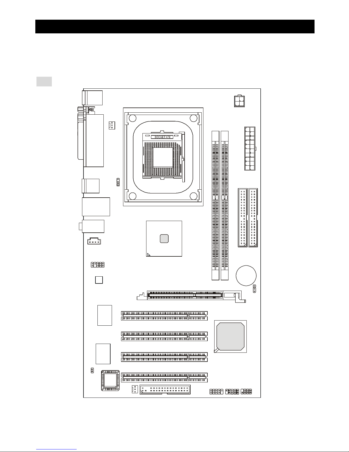
简介
感谢您购买 845PE –V2 Series(MS-7154)v1.X Micro ATX 主板。845PE –V2 Series是基于 Intel ® 845PE
& Intel ® ICH4芯片组,它提供了 6 个 USB 2.0 端口,可实现高速数据传输。845PE –V2 Series 提供了
高性能、专业化的桌面平台解决方案。
布局
Page 22

18
规格
CPU
l 支持 Socket 478 接口的 P4处理器( Northwood/Prescott核心)400MHz/533MHz/800MHz(超频支
持到 800MHz)
l 支持到 3.4GHz 或更高频率
(要了解关于 CPU 的最新信息,请访问
http://www.msi.com.tw/program/products/mainboard/mbd/pro_mbd_cpu_support.php )
芯片组
l Intel ® 845PE
- 支持 FSB 400MHz/533MHz/800MHz(超频支持到 800MHz)
- 支持 DDR266/333/400(超频支持到 DDR400)技术
l Intel ® ICH4
- 集成了 AC97 控制器
- 6个高速的 USB 2.0 端口,速度可达 480Mb/sec.
- 支持 ACPI 和传统 legacy APM 电源管理
- Legacy免支持
主内存
l 支持 2 条 184-pin 无缓冲的 DDR 266/333/400(超频支持到 DDR400)内存
l 支持无 ECC 内存,最高支持到 2GB
(要了解内存模组支持的更新详情,请访问
http://www.msi.com.tw/program/products/mainboard/mbd/pro_mbd_trp_list.php )
插槽
l 1条AGP(加速图形端口)插槽,支持 AGP 2.0 4X/2X
l 4条PCI 2.2 32-bit Master PCI总线插槽(支持 3.3V/5V PCI总线界面)
板载 IDE
l 2个IDE 控制器,集成于 Intel ® ICH4 中
l 支持 Bus Master、Ultra DMA 33/66/100工作模式
l 最多可连接 4 台 IDE 设备
板载周边
l 板载周边包括:
Page 23

19
- 1个软驱接口,支持 1台 360K, 720K, 1.2M, 1.44M 和 2.88 Mbytes 的软驱
- 1个串行端口(COMA)
- 1个并行端口,支持 SPP/EPP/ECP 模式
- 6个USB 2.0/1.1 端口(后置* 4 / 前置* 2)
- 1组Line-In/Line-Out/Mic-In 端口
- 1个RJ-45 LAN 接口
音频
l AC97连接控制器集成于 Intel ® ICH4 中
l 6 声道 S/W 音频编解码芯片 AD1888
- 符合 AC97 2.2规格
- 满足 PC2001音频性能要求
LAN
l Broadcom 4401 PCI2.2 LAN
- 支持 10Mb/s 和 100Mb/s 自适应模式
- 符合 PCI 2.2 和 PC99标准
BIOS
l 支持 PNP BIOS, ACPI, SMBIOS 2.3, Green 和 Boot Block 的 2MB Award BIOS
l 提供了 DMI 2.0, WFM 2.0, WOL,机箱入侵侦测和 SMBus,便于系统管理
规格
l ATX规格尺寸:30.5 cm (L) x 17.5 cm (W).
固定孔
l 6个固定孔
Page 24
20
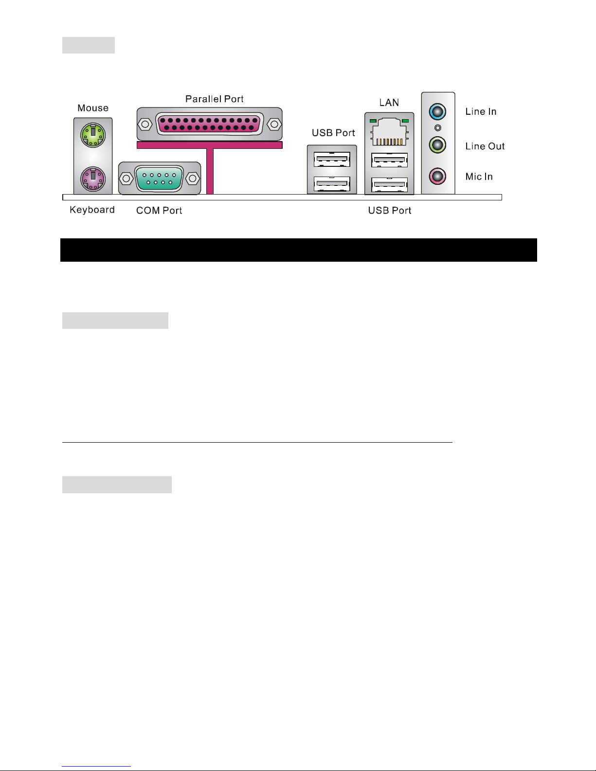
后置面板
后置面板提供了以下接口:
硬件安装
这一章主要告诉您如何安装 CPU、内存、扩展卡,也会告诉您怎样设置主板上的跳线,并提供连接外围
设备的指导,如鼠标,键盘等。安装时,请谨慎拿各零部件并且按照安装说明的步骤进行。
中央处理器:CPU
本主板支持 478 针脚封装的 Intel Pentium 4 Northwood 和 Prescott Celeron 处理器。主板使用的是
PGA478 的 CPU插槽,可使 CPU 安装过程简化。当您在安装 CPU 时,请务必确认您使用的 CPU 带有
防过热的散热片和降温风扇。如果您的 CPU没有散热片和降温风扇,请与销售商联系,购买或索取以上
设备,并在开机之前妥善安装。(要了解关于 CPU的最新信息,请访问
http://www.msi.com.tw/program/products/mainboard/mbd/pro_mbd_cpu_support.php )
CPU 核心速度推导
如果 CPU 时钟频率 = 133MHz
核心/总线倍频 = 23
那么 CPU 核心频率 = 主时钟频率 x 核心/总线倍频
= 133MHz x 23
= 3.06 GHz
Page 25
21
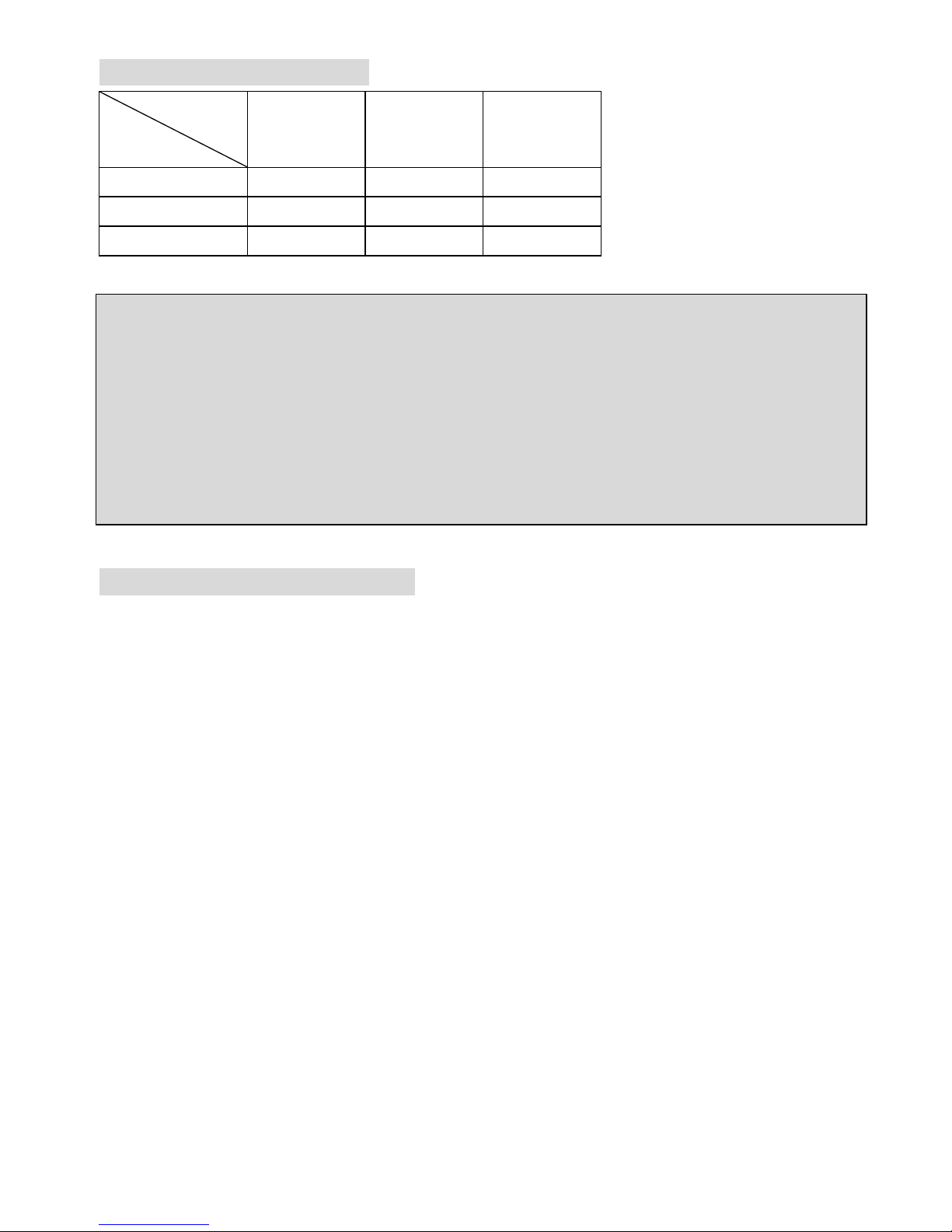
内存速度/CPU FSB 支持列表
内存
FSB
DDR 266 DDR 333 DDR 400*
400 MHz OK OK OK
533 MHz OK OK OK
800 MHz* OK OK OK
* 仅对于超频
微星提醒您...
温度过高
温度过高会严重损害 CPU 和系统,请务必确认所使用的降温风扇始终能够正常工作,保护 CPU 以免过
热烧毁。
更换 CPU
更换 CPU时,请先关闭 ATX电源供应或拔掉电源插头以确保 CPU 的安全。
Socket 478 针脚封装的 CPU 安装
1. 安装前请先关掉电源并且拔掉电源线。
2. 将拉杆从插槽上拉起,与插槽成 90 度角。
3. 寻找 CPU 上的圆点/切边。此圆点/切边应指向拉杆的旋轴,只有方向正确 CPU 才能插入。
4. 如果 CPU 是正确安装的,针脚应该完全嵌入进插座里并且不能被看到。请注意任何违反正确操作
的行为都可能导致主板的永久性破坏。
5. 稳固的将 CPU 插入到插座里并且关上拉杆。当拉上拉杆时 CPU 可能会移动,一般关上拉杆时用
手指按住 CPU 的上端,以确保 CPU 正确的而且是完全的嵌入进插座里了。
Page 26

22
安装 CPU风扇
在新技术的推动下,使处理器可以运行在更高的频率下,速度更快,效能更好,热量的控制也变得越来
越重要。为了驱散热量,您应 在 CPU 上方安装合适的散热片和降温风扇。请按照以下步骤完成散热片和
风扇的安装:
1. 在主板上找到 CPU 及其支架的位置。
2. 把散热片妥善定位在支撑机构上。
3. 将冷却风扇安装在散热片的顶部。下压风扇直到它的四个卡子嵌入支撑机构上对应的孔中。
4. 将两个压杆压下以固定风扇。每个压杆都只能沿一个方向压下。
5. 将风扇的电源线从安装好的风扇引出,接在主板上 3 针的 CPU 风扇电源接头上。
内存
主板提供了 2 个 184-pin 无缓冲的 DDR266/DDR333/DDR400 SDRAM,支持的最大容量为 2GB。您至
少要安装一条内存在插槽,以保证系统正常工作。
(要了解内存模组支持的更新,请访问
http://www.msi.com.tw/program/products/mainboard/mbd/pro_mbd_trp_list.php )
至少要安装一条内存模组在插槽。内存模组可以按任何次序被安装。您也可以根据自己的需要,来安装
单面或双面的内存模组。
安装 DDR 内存
1. DDR DIMM 内存条的中央仅有一个缺口。
2. 将 DDR 内存垂直插入 DDR 插槽中,并确保缺口的正确位置。
3. DIMM 插槽两边的塑料卡口会自动闭合。
NotchVolt
Page 27

23
电源适配器
主板使用 ATX 结构的电源适配器给主板供电。在连接电源适配器之前,请务必确认所有的组件都已正确
安装,并且不会造成损坏。建议您使用功率为 300W 或以上的电源。
ATX 20-Pin 电源接口:PWR1
此接口可连接 ATX电源适配器。在与 ATX电源适配器相连时,请务必确
认,电源适配器的接头安装方向正确,针脚对应顺序也准确无误。将电源
接头插入,并使其与主板电源接口稳固连接。
ATX 12V 电源接口:JPW1
此 12V 电源接口用于为 CPU 供电。
132
4
GND
GND
12V
12V
软盘驱动器接口:FDD1
主板提供了一个标准的软盘驱动器接口 FDD,支持 360K, 720K,
1.2M, 1.44M 和 2.88M 的软盘驱动器
机箱入侵开关接头:JCI1
此接头可与一个2-pin 机箱开关相连。如果机箱被打开,此接头会短接,系统会记
录此状态,并在屏幕上显示警告信息。要消除这一警告信息,您必须进入 BIOS 设定工具清除此记录。
CD-In 接口:JCD1
此接口为 CD-ROM 的音频接口。
风扇电源接口:CPUFAN1/SYS_FAN1
CPUFAN1(处理器风扇)、 SYS_FAN1(系统风扇)支持+12V的系统散热风扇,
使用 3 -pin 接头。当您将接线接到风扇接头时请注意红色线为正极,必须接到
+12V,而黑色线是接地,必须接到 GND 。如果您的主机板有系统硬件监控芯片,
您必须使用一个特别设计的支持速度侦测的风扇方可使用此功能。
3.3V
-12V
GND
GND
PW_OK
-5V
5V_SB
5V
12V
PS_ON
10
20
11
1
GND
GND
5V
GND
GND
GND
5V
5V
3.3V
3.3V
2
1
GND
CINTRO
GND
L
R
Page 28

24
微星提醒您...
1. 请询问厂商以使用适当的 CPU 降温风扇。
2. CPUFAN1支持风扇功能。您可以安装 PC Alert 工具,它可根据 CPU 实际温度,自动控制 CPU 风
扇速度。
IDE 接口:IDE1 & IDE2
主板有一个 32-bit增强 PCI IDE 和 Ultra DMA 33/66/100/133 控制器,提供 IDE 接口设备工
作于 PIO 模式 0-4,Bus Master 和 Ultra DMA 33/66/100/133 等功能。您共可使用四个 IDE
设备,如硬盘,CD-ROM、 120MB 软驱或其它 IDE 设备。
第一个硬盘必须与 IDE1 接口相连。您可以将一个主盘和一个从盘与 IDE1 相连接。您必须通
过硬盘的相应跳线把第二个硬盘设置为从盘模式。您可以将一个主盘和一个从盘与 IDE2 相连
接。
微星提醒您...
如果您打算在一条硬盘线上连接两个硬盘,您必须将第二个硬盘设为从盘。请参考硬盘所附的说明手册
设定主/从盘模式。
前置面板接口:JFP1 & JFP2
主板提供了 2组机箱面板和电源开关、指示灯的连接接口 JFP1和
JFP2。JFP1 是符合 Intel I/O 面板连接设计向导的。
前置音频接口:JAUD1
您可以在前置面板接口 JAUD1上连接一个音频接口,JAUDIO1是符
合 Intel® I/O 面板连接设计向导的。
微星提醒您...
如果您不想使用前置音频,针脚 5 & 6, 9 & 10 必须用跳线帽短接,这样输出信号才会转到后面的音频端
口。否则后面的 Line-Out 音频接口将不起作用。
1
2
9
10
Page 29

25
前置 USB接口:JUSB1
主板提供 1个标准的 USB2.0 接口 JUSB1。USB 2.0 技术提高数据传输的
速率达到 480Mbps,是 USB1.1 的 40倍。它可连接高速数据传输速率的
USB 界面周边设备,如 USB HDD、数码相机、MP3播放器、打印机、调
制解调器等。
微星提醒您...
请注意,VCC 和 GND 的针脚必须安插正确,否则会引起主板的损毁。
键盘/鼠标电压跳线:JPUSB1
此跳线是用于设置键盘/鼠标的电压。默认值为 VCC5(1~2)。
VCC5 5V 备用
清除 CMOS跳线:JBAT1
主板上建有一个 CMOS RAM,其中保存的系统配置数据需要通过一枚外置电池来维持。CMOS RAM 是
在每次启动计算机的时候引导操作系统的。若您想清除保存在 CMOS RAM 中的系统配置信息,可使用
JBAT1(清除 CMOS 跳线)清除数据。请按照以下方法清除数据:
1 1
3
Keep Data Clear Data
1
3
微星提醒您...
在系统关闭时,您可通过短接 2-3 针脚来清除 CMOS 数据。然后,返回到 1-2 针短接的状态。请避免在
系统开机时清除 CMOS,这样可能会对主板造成损害。
Page 30

26
AGP(高级图像端口)插槽
AGP 插槽可让您插入 AGP显卡,它是专为 3D 图形显示而设计的一种接口规范。它为图形 控制器对主内
存的直接访问提供一个 66MHz,32-bit 专用通道。本主板支持 2x/4x 1.5V 的 AGP卡。
PCI(周边设备连接)插槽
PCI 插槽可安装您所需要的扩展卡。当您在安装或拆卸扩展卡的时候,请务必确认已将电源插头拔除。
同时,请仔细阅读扩展卡的说明文件,安装和设置此扩展卡必须的硬件和软件,比如跳线或 BIOS 设置。
PCI 中断请求队列
IRQ 是中断请求队列和中断请求确认的缩写,将设备的中断信号送到微处理器的硬件列表。PCI 的 IRQ
针脚一般都是连接到如下表所示的 PCI 总线的 INT A# ~ INTD# 引脚:
Order1 Order2 Order3 Order4
PCI Slot 1 INT B# INT C# INT D# INT A#
PCI Slot 2 INT C# INT D# INT A# INT B#
PCI Slot 3 INT D# INT A# INT B# INT C#
PCI Slot 4 INT B# INT C# INT D# INT A#
Page 31

27
BIOS 设置
计算机加电后,系统将会开始 POST (加电自检)过程。当屏幕上出现以下信息时,按<DEL>键即可进
入设定程序。
DEL: Setup
如果信息在您做出反应前就消失了,而您仍需要进入 Setup,请关机后再开机或按机箱上的 Reset 键, 重
启您的系统。您也可以同时按下<Ctrl>、<Alt>和<Delete>键来重启系统。
主页面
Standard CMOS Features(标准 CMOS 特性设定)
使用此菜单可对基本的系统配置进行设定。如时间,日期等。
Advanced BIOS Features(高级 BIOS 特性设定)
使用此菜单可对 Award®系统的高级特性进行设定。
Advanced Chipset Features(高级芯片组特性设定)
使用此菜单可以修改芯片组寄存器的值,优化系统的性能表现。
Integrated Peripherals(整合周边设定)
使用此菜单可以对周边设备进行特别的设定。
Power Management Setup(电源管理特性设定)
使用此菜单可以对系统电源管理进行特别的设定。
PNP/PCI Configurations(PnP/PCI配置)
此项仅在您系统支持 PnP/PCI 时才有效。
Page 32

28
H/W Monitor(硬件监视)
此项显示了您 PC 硬件的当前状态,例如 CPU、风扇等。
Frequency/Voltage Control(频率/电压控制)
使用此菜单可以进行频率和电压的特别设定。
Load Fail-Safe Defaults(载入故障保护缺省值)
使用此菜单可以载入主板厂商设定的 BIOS设定值,以确保系统的稳定性。
Load Optimized Defaults(载入优化设置缺省值)
使用此菜单可以载入系统优化性能设置的 BIOS 值,但此缺省值可能会影响系统的稳定性。
BIOS Setting Password(BIOS 设置密码)
使用此项以设定 BIOS设置密码。
Save & Exit Setup(保存后退出)
保存对 CMOS的修改,然后退出 Setup 程序。
Exit Without Saving(不保存退出)
放弃对 CMOS的修改,然后退出 Setup 程序。
Page 33
29
频率/电压控制
Current CPU Clock(当前 CPU 时钟)
在此项中,显示了 CPU的当前频率,只读。
Adjust Memory Frequency(调整内存倍频)
当此项在高性能模式中设置为[Manual],您可人为地设置内存频率限制。请 注 意 ,要 避 免内存运行速度高
于此限值。设定值:[PC100], [PC133], [Auto]。
Auto Detect PCI Clk(自动侦测PCI 时钟)
此项用于自动侦测 PCI 插槽。当设置为[Enabled],系统将移除(关闭)闲置的 PCI 插槽时钟,以最小化
电池干扰(EMI)。 设定值有:[Enabled], [Disabled]。
Spread Spectrum(频展)
当主板上的时钟震荡发生器工作时,脉冲的极值(尖峰)会产生 EMI(电磁干扰)。频率范围设定功能可
以降低脉冲发生器所产生的电磁干扰,所以脉冲波的尖峰会衰减为较为平滑的曲线。如果您没有遇到电
磁干扰问题,将此项设定为[Disabled],这样可以优化系统的性能表现和稳定性。但是如果您被电磁干扰
问题困扰,请将此项设定为[Enabled] ,这样可以减少电磁干扰。注意,若您超频使用,必须将此项禁用。
因为即使是微小的峰值漂移(抖动)也会引入时钟速度的短暂突发,这样会导致您超频的处理器锁死。
CPU Clock(CPU时钟)
此项可让您选择 CPU 前端系统总线的频率(以 MHz 为单位), 通 过 调 整 FSB到更高频率对处理器进行
超频。
Adjust CPU Ratio(调整 CPU 倍频)
此项可让您调整 CPU 倍频。设定范围从[8]到[50]。
Page 34
30
Memory Voltage(内存电压)
调整 DDR 电压可以提高 DDR 速度。但这样的调整会影响系统的稳定性,所以建议您不要改变默认设置
作为长期使用。
AGP Voltage(AGP电压)
AGP 电压可在此项做调整,可让您在超频时提高 AGP 卡的性能,但这样会影响系统的稳定性。所以建
议您不要改变默认设置作为长期使用。 设定值从 1.5V 到 1.8V,以 0.1V 为单位。
载入优化设置缺省值
您可载入主板制造商提供的 BIOS 优化设置缺省值,以优化系统性能。
 Loading...