

Page 1

CHAPTER 1 INTRODUCTION
Chapter 1
INTRODUCTION
The MS-6312 Flex A TX WH11 mainboard is a high-performance computer
mainboard based on Intel® 810 (810/810 DC100/810e) chipset. The MS-6312
is designed for the Intel® Pentium III(FC-PGA) or CeleronTM processor for
inexpensive business/personal desktop markets.
The Intel® 810 chipset is the first generation Integrated Graphics chipset for
the Intel® CeleronTM processor. The graphics accelerator architecture
consists of dedicated multi-media engines executing in parallel to deliver
high performance 3D, 2D, and motion compensation video capabilities. An
integrated centralized memory arbiter allocates memory bandwidth to
multiple system agents to optimize system memory utilization. A new
chipset component interconnect, the hub interface, is designed into the Intel
810 chipset to provide an efficient communication channel between the
memory controller hub and I/O hub controller.
The series of Intel® 810 chipset contains three core components: the
Graphics and Memory Controller Hub (GMCH), the I/O Controller Hub (ICH)
and the Firmware Hub (FWH). The GMCH integrates a 66/100MHz for 810
and 810 DC100 and 66/100/133 MHz for 810e, P6 family system bus controller, 2D/3D graphics accelerator , 100MHz SDRAM controller and high-speed
hub interface for communication with the ICH. The ICH integrates an Ultra
A T A 33(ICHO)/66(ICH) controller , USB host controller, LPC interface
controller, FWH interface conroller , PCI interface controller, AC’97 digital
controller and a hub interface for communication.
The Intel® 82802 Firmware Hub (FWH) component is part of the series of
Intel® 810 chipset. The FWH is key to enabling future security and manage-
ability infrastructure for the PC platform.
1-1
Page 2

CHAPTER 1 INTRODUCTION
1.1 Mainboard Features
CPU
l Support Socket370 for Intel® Celeron
TM
and Pentium III(FC-PGA) proces-
sor.
l Support 366MHz, 400MHz, 433MHz, 466MHz, 500MHz, 550MHz,667Mhz
or higher
Chipset
l Support the series of Intel® 810 (810/810DC100/810E) chipset.
l Intel® GMCH chipset. (421 BGA)
- Integrated Graphics Controller
- Intel DDM+ Architecture
- SDRAM memory Independent of System Bus
l Intel® ICH chipset. (241 BGA)
- AC’97 Controller Integrated
- 2 full IDE channels, up to A TA66
- Low pin count interface for SIO
Front Side Bus (FSB)
l 66/100/133MHz clocks are supported.
Main Memory
l Support two 168-pin DIMM sockets.
l Support a maximum memory size of 256MB(64Mbit technology) or
512MB(128Mbit technology) SDRAM.
Slots
l T wo 32-bit Master PCI Bus slots.
l Support 3.3v/5v PCI bus Interface.
On-Board IDE
l An IDE controller on the ICH chipset provides IDE HDD/CD-ROM with
PIO, Bus Master and Ultra DMA/66 operation modes.
l Can connect up to four IDE devices.
1-2
Page 3

CHAPTER 1 INTRODUCTION
On-Board Peripherals
l On-Board Peripherals include:
- 1 floppy port supports 2 FDD with 360K, 720K, 1.2M, 1.44M
and 2.88Mbytes.
- 1 serial header (optional)
- 1 parallel port supports SPP/EPP/ECP mode (optional)
- 5 USB ports(3 USB rear ports + 2 USB front headers--optional)
- 1 IrDA connector for SIR. (optional)
- 1 VGA port
- 1 DVI (optional)
- 3 Audio port (optional)
Video
l GMCH chip integrated
l 2D/3D Graphics
l Onboard 4MB SDRAM Display Cache (optional)
l Silicon Image Sil164 support Digital Output (optional)
Audio
l ICH chip integrated
l AC’97 2.1 Compliant
l Auto Sensing SPDIF Support
Modem
l Conexant Smart MCII & SmartDAA
TM
V .90 (optional)
- Based on the company’s patented DIB (Digital Isolation Barrier)
technology which provides an error free and reliable digital communication channel.
- Provides better performance with an isolation barrier while
mimimizing signal distortion.
an isolation barrier while minimizing
BIOS
l The mainboard BIOS provides “Plug & Play” BIOS which detects the
peripheral devices and expansion cards of the board automatically .
l The mainboard provides a Desktop Management Interface(DMI) function
1-3
Page 4

CHAPTER 1 INTRODUCTION
which records your mainboard specifications.
Dimension
l Flex A TX Form Factor: 7.5” x 9” inches
Mounting
l 6 mounting holes.
Warning: According to Intel 810 chipset specification: 810E chipset sup-
ports 66/100/133 MHz FSB processor and 810/810DC100 chipset
supports 66/ 100 FSB processor. Please do not use 133MHz FSB
processor on motherboards which use 810/810DC100 chipset.
Note: T o be able to identify the chipset used onboard. During POST
(Power on Self T est), you can determine the chipset, which will
appear briefly at the bottom left of the POST screen.
1-4
Page 5
Socket
CHAPTER 1 INTRODUCTION
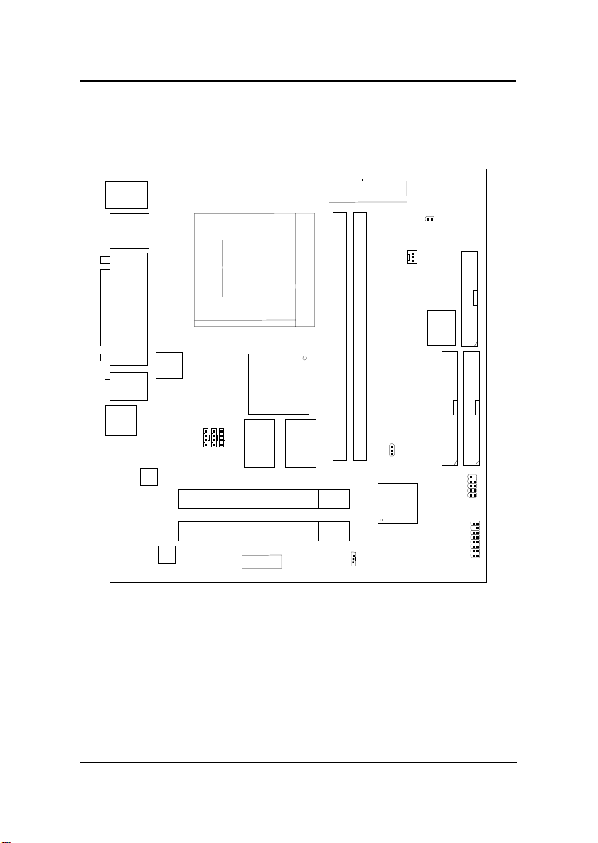
1.2 Mainboard Layout
Top: mouse
Bottom:
keyboard
USB
Ports
Top: LPT
Bottom:
VGA Port
DVI Port
Line-Out
Line-In
Mic
RJ-11
CODEC
SIlicon
Image
Sil164CT
Conexant
SmartMCII
JTAD1
VIDEO
CD_IN
PCI SLOT 1
Intel
GMCH
Chipset
(810/810DC100/810e)
SDRAM
PCI SLOT 2
BATT
+
SDRAM
ATX
Power Supply
DIMM 1
DIMM 2
JWOL1
JCMOS1
ICH
CPUFAN
JCASE1
FWH
IDE2
JGUSB1
FDD
IDE1
JFP2
MS-6312 Flex A TX WH1 1 Mainboard
1-5
Page 6
CHAPTER 2 HARDWARE INSTALLATION
Chapter 2
HARDWARE INSTALLATION
2.1 Central Processing Unit: CPU
The mainboard operates with Intel® Pentium III(FC-PGA)/Celeron
TM
processor . The mainboard uses a CPU socket called Socket 370 for easy
CPU installation. The CPU should always have a Heat Sink and a cooling
fan attached to prevent overheating.
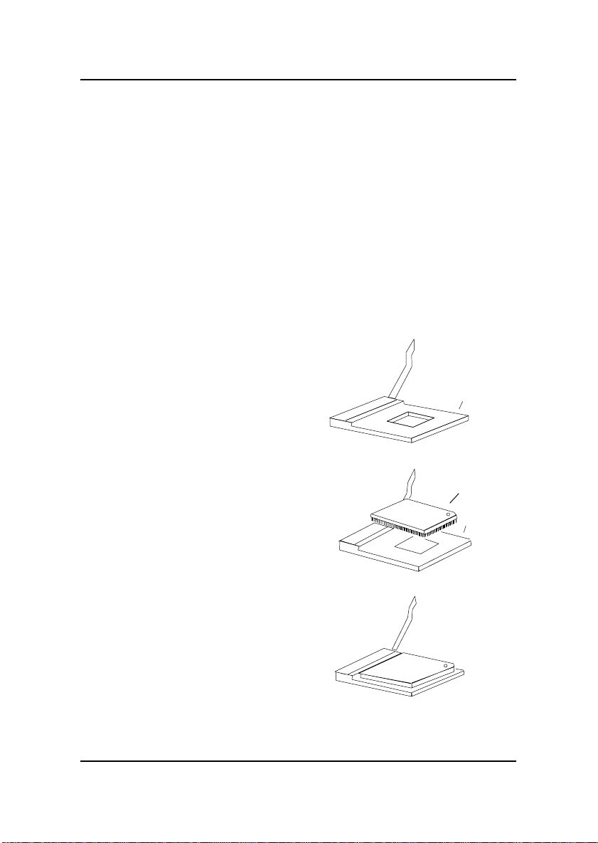
2.1-1 CPU Installation Procedures
1 . Pull the lever sideways away
from the socket. Then, raise
the lever up to a 90-degree
angle.
2 . Locate Pin 1 in the socket
and look for the white dot or
cut edge in the CPU. Match
Pin 1 with the white dot/cut
edge. Then, insert the CPU.
It should insert easily.
3. Press the lever down to
complete the installation.
Sliding
Plate
Open Lever
CPU
Close
Lever
Pin 1
White dot/
Cut edge
Pin 1
2-1
CPU
Page 7

CHAPTER 2 HARDWARE INSTALLATION
2.1-2 CPU Core Speed Derivation Procedure
The mainboard CPU Bus Frequency can be set through BIOS setup
If CPU Clock = 66MHz
Core/Bus ratio = 3. 5
then CPU core speed = Host Clock x Core/Bus ratio
= 66MHz x 3.5
= 233MHz
2-2
Page 8
CHAPTER 2 HARDWARE INSTALLATION
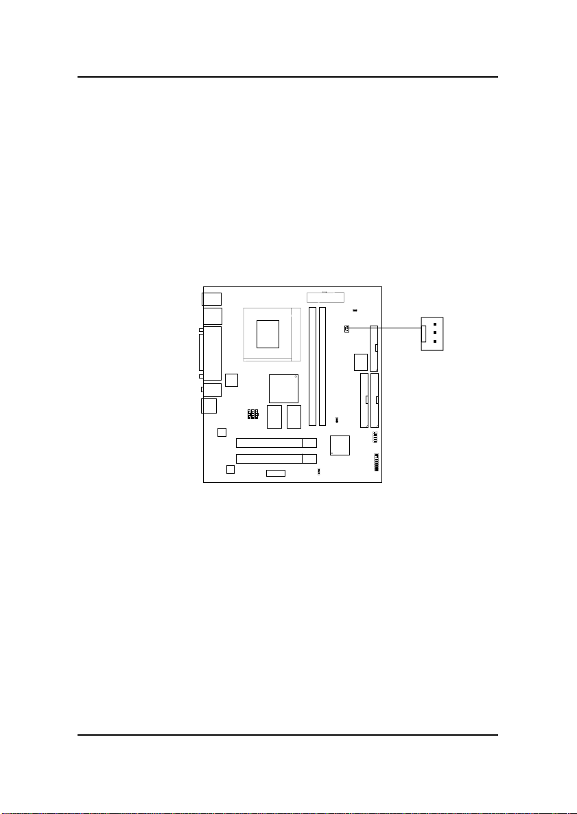
2.1-4 Fan Power Connector: CPUFAN
This connector support system cooling fan with + 12V. It supports three pin
head connector. When connecting the wire to the connector, always take
note that the red wire is the positive and should be connected to the +12V,
the black wire is Ground and should be connected to GND. If your
mainboard has System Hardware Monitor chipset on-board, you must use a
specially designed fan with speed sensor to take advantage of this function.
GND
+12V
SENSOR
CPUFAN
CPUFAN: Processor Fan
For fans with fan speed sensor, every rotation of the fan will send out 2
pulses. System Hardware Monitor will count and report the fan rotation
speed.
Note: 1. Always consult vendor for proper CPU cooling fan.
2. CPU F AN supports the FAN control. Y ou can install PC Alert
utility. This will automatically control the CPU FAN Speed according
to the actual CPU temperature.
2-3
Page 9
CHAPTER 2 HARDWARE INSTALLATION
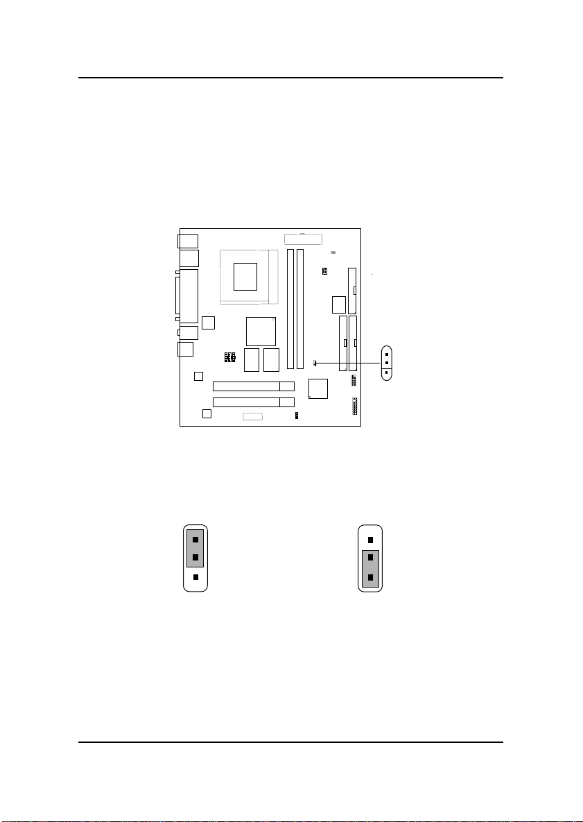
2.2 Clear CMOS Jumper: JCMOS1
A battery must be used to retain the mainboard configuration in CMOS
RAM. Short 1-2 pins of JCMOS1 to store the CMOS data.
3
1
JCMOS1
3
2
1
Clear Data
Keep Data
3
2
1
Note: Y ou can clear CMOS by shorting 2-3 pin, while the system is of f.
Then, return to 1-2 pin position. A void clearing the CMOS while
the system is on, it will damage the mainboard. Always unplug
the power cord from the wall socket.
2-4
Page 10
CHAPTER 2 HARDWARE INSTALLATION
2.3 Memory Installation
2.3-1 Memory Bank Configuration
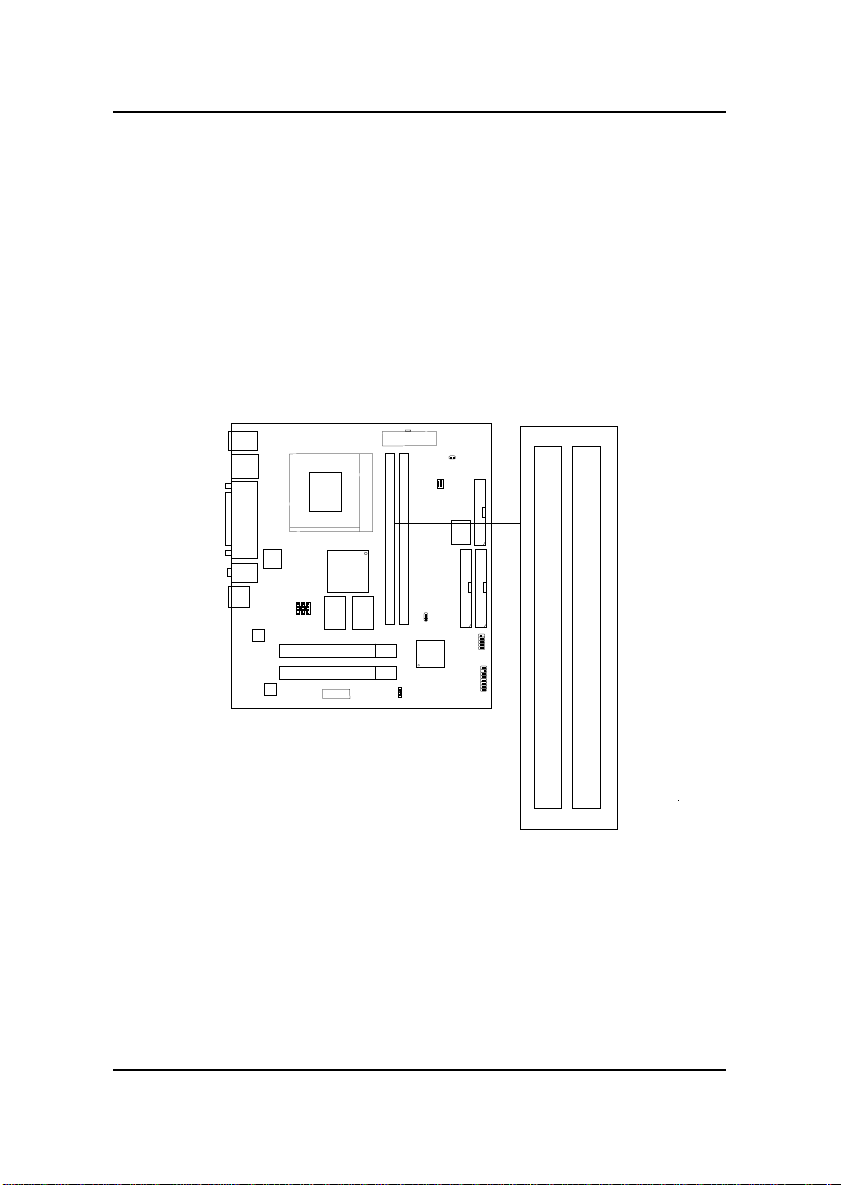
The mainboard supports a maximum memory size of 256MB(64-bit technology) or 512MB(128-bit technology for SDRAM: It provides two 168-pin
unbuffered DIMMs (Double In-Line Memory Module) sockets. It supports
8 MB to 128 Mbytes DIMM memory module.
2-5
DIMM1(Bank0 + Bank1)
DIMM2(Bank2+ Bank3)
Page 11
CHAPTER 2 HARDWARE INSTALLATION
2.3-2 Memory Installation Procedures
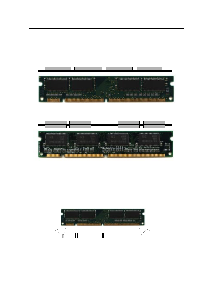
A. How to install a DIMM Module
Single Sided DIMM
Double Sided DIMM
1. The DIMM slot has 2 Notch Keys “VOL T and DRAM”, so the
DIMM memory module can only fit in one direction.
2. Insert the DIMM memory module vertically into the DIMM slot.
Then push it in.
VOLTDRAM
3. The plastic clip at the side of the DIMM slot will automatically
close.
2-6
Page 12

CHAPTER 2 HARDWARE INSTALLATION
2.3-3 Memory Population Rules
1 . Supports only SDRAM DIMM.
2 . To operate properly , at least one 168-pin DIMM module must be installed.
3. This mainboard supports Table Free memory, so memory can be installed
on DIMM1 or DIMM 2 in any order.
4. Supports 3.3 volt DIMM.
5. The DRAM addressing and the size supported by the mainboard is
shown below:
T able 2.3-1 SDRAM Memory Addressing
DRAM
Tech.
16M 1Mx16 ASYM 1 1 8 8MB x 4 16MBx8
64M 2Mx32 ASYM 1 1 9 32MBx2 64MBx4
64M 2Mx32 ASYM 1 1 8 16MB 32MB
DRAM
Density &
Width
2Mx8 ASYM 11 9 16MBx8 32MBx16
2Mx32 ASYM 12 8 16MBx2 32MBx4
4Mx16 ASYM 11 10 32MB 64MB
4Mx16 ASYM 13 8 32MB 64MB
8Mx8 ASYM 13 9 64MB 128MB
4Mx16 ASYM 12 8 --- ---
8Mx8 ASYM 12 9 --- ---
DRAM
Addressing
Address Size
Row
Column
MB/DIMM
Single
Side(S)
no.
pcs.
Double
Side(D)
2-7
no.
pcs.
Page 13
CHAPTER 2 HARDWARE INSTALLATION
2.4 Case Connector: JFP2
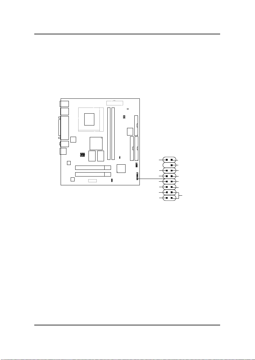
The Power Switch, Reset Switch, Power LED, IR, and HDD LED are all
connected to the JFP2 connector block.
VCC5
GND
NC
GND
PW-BTN
PLED2
PLED1
JFP2
IRTX
GND
IRRX
VCC5
Reset
GND
+
HDD
2-8
Page 14

CHAPTER 2 HARDWARE INSTALLATION
2.4-1 Power Switch
Connect to a 2-pin push button switch. This switch has the same feature
with JRMS1.
2.4-2 Reset Switch
Reset switch is used to reboot the system rather than turning the power ON/
OFF . A void rebooting while the HDD LED is lit. You can connect the Reset
switch from the system case to this pin.
2.4-3 Power LED
The Power LED is lit while the system power is on. Connect the Power LED
from the system case to this pin. The 2-pin dual color LED(ACPI request).
a. 2 pin dual color LED
GREEN Color: Indicate the system is in full on mode.
ORANGE Color: Indicate the system is in suspend mode.
2.4-4 InfraRed
The InfraRed or IR connector is a wireless transmitting and receiving
infrared.
2.4-5 HDD LED
HDD LED shows the activity of a hard disk drive. A void turning the power
off while the HDD led is lit. Y ou can connect the HDD LED from the system
case to this pin.
2-9
Page 15
CHAPTER 2 HARDWARE INSTALLATION
2.5 Floppy Disk Connector: FDD
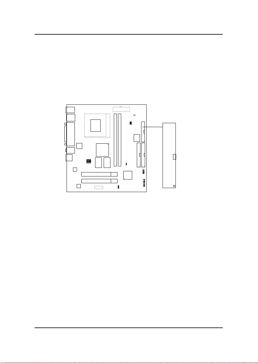
The mainboard also provides a standard floppy disk connector FDD that
supports 360K, 720K, 1.2M, 1.44M and 2.88M floppy disk types. This
connector supports the provided floppy drive ribbon cables.
FDD
1
2-10
Page 16
CHAPTER 2 HARDWARE INSTALLATION
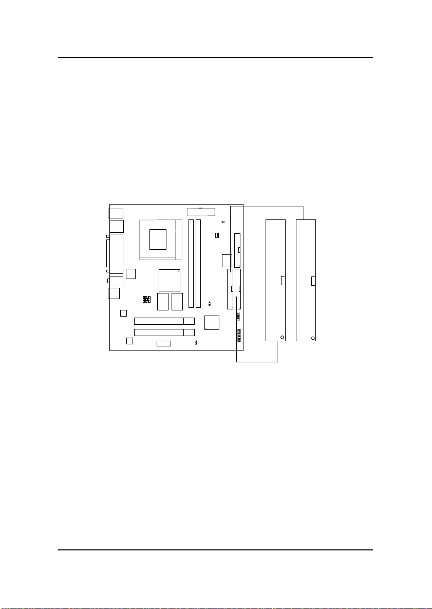
2.6 Hard Disk Connectors: IDE1 & IDE2
The mainboard has a 32-bit Enhanced PCI IDE and Ultra DMA/66 (ICH)/
Ultra DMA/33(ICH0) Controller that provides PIO mode 0~4, Bus Master,
and Ultra DMA/33 function. It has two HDD connectors IDE1 (primary) and
IDE2 (secondary). Y ou can connect up to four hard disk drives, CD-ROM,
120MB Floppy (reserved for future BIOS) and other devices to IDE1 and
IDE2. These connectors support the provided IDE hard disk cable.
Secondary IDE Connector
Primary IDE Connector
1
1
IDE1(Primary IDE Connector)
The first hard drive should always be connected to IDE1. IDE1 can
connect a Master and a Slave drive. You must configure second hard
drive to Slave mode by setting the jumper accordingly .
IDE2(Secondary IDE Connector)
IDE2 can also connect a Master and a Slave drive.
2-11
Page 17
CHAPTER 2 HARDWARE INSTALLATION
2.7 Power Supply
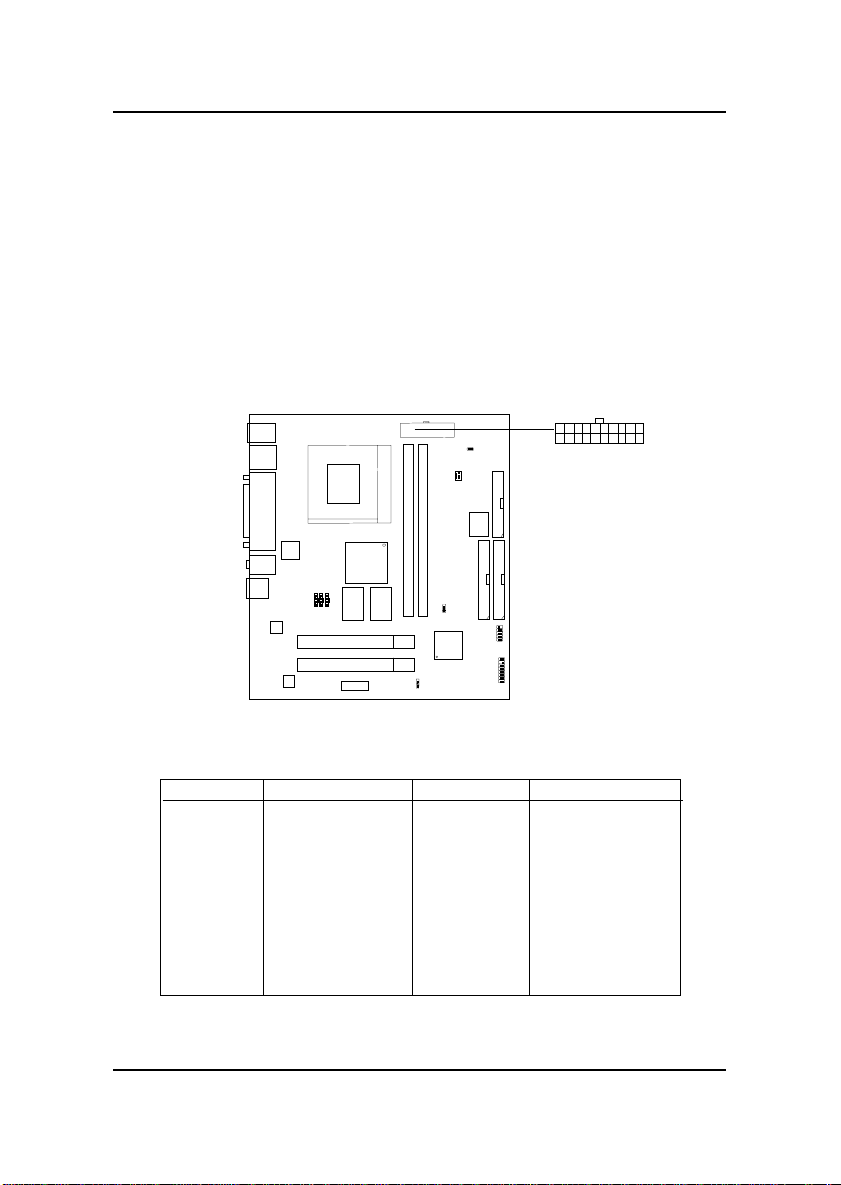
2.7-1 ATX 20-pin Power Connector: JWR1
This connector supports the power button on-board. Using the ATX power
supply, functions such as Modem Ring Wake-Up and Soft Power Off are
supported by this mainboard. This power connector supports instant power
on function which means that system will boot up instantly when the power
connector is inserted on the board.
20
10 1
Power Connector
11
ATX
PIN DEFINITION
PIN SIGNAL
1 3.3V
2 3.3V
3 GND
45V
5 GND
65V
7 GND
8 PW_OK
9 5V_SB
10 12V
Warning: Since the mainboard has the instant power on function, make
sure that all components are installed properly before inserting the power
connector to ensure that no damage will be done.
PIN SIGNAL
11 3.3V
12 -12V
13 GND
14 PS_ON
15 GND
16 GND
17 GND
18 -5V
19 5V
20 5V
2-12
Page 18
CHAPTER 2 HARDWARE INSTALLATION
2.8 Mouse Connector: JKBMS1
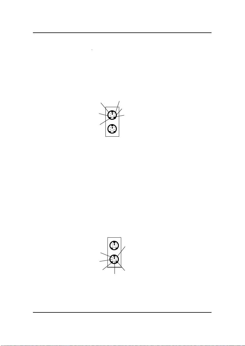
The mainboard provides a standard PS/2® mouse mini DIN connector for
attaching a PS/2® mouse. You can plug a PS/2® mouse directly into this
connector. The connector location and pin definition are shown below:
Pin5
Pin6
NC
Pin4
VCC
Pin2
NC
PS/2 Mouse (6-pin Female)
Mouse Clock
Pin3
GND
Mouse DATA
Pin1
2.9 Keyboard Connector: JKBMS1
The mainboard provides a standard PS/2® keyboard mini DIN connector for
attaching a keyboard. You can plug a keyboard cable directly to this
connector.
Pin5
KBD Clock
Pin6
NC
Pin4
VCC
Pin2
NC
KBD DATA
Pin1
Pin3
GND
PS/2 Keyboard (6-pin Female)
2-13
Page 19
CHAPTER 2 HARDWARE INSTALLATION
2.10 USB Connectors
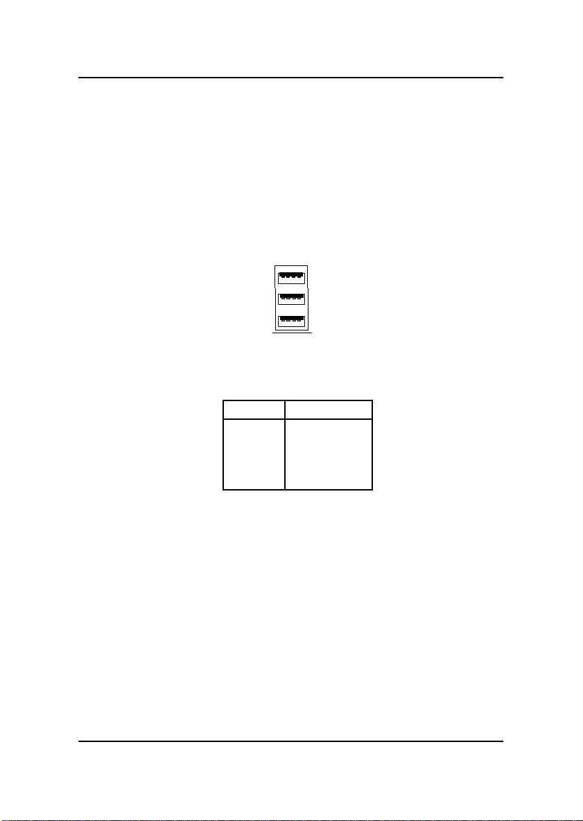
The mainboard provides a UHCI(Universal Host Controller Interface)
Universal Serial Bus root for attaching USB devices like: keyboard, mouse
and other USB devices. You can plug the USB device directly to this
connector.
1 2 3 4
USB Ports
PIN SIGNAL
1 VCC
2 -Data
3 +Data
4 GND
2-14
Page 20
CHAPTER 2 HARDWARE INSTALLATION
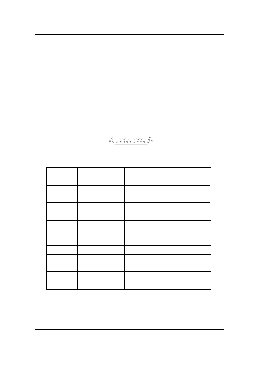
2.11 Parallel Port Connector: LPT1
The mainboard provides a 25 pin female centronic connector for LPT . A
parallel port is a standard printer port that also supports Enhanced Parallel
Port(EPP) and Extended capabilities Parallel Port(ECP). See connector and
pin definition below:
Parallel Port (25-pin Female)
LPT 1
13
1
25
14
PIN DEFINITION
PIN SIGNAL PIN SIGNAL
1 STROBE 14 AUTO FEED#
2 DAT A0 15 ERR#
3 DATA1 16 INIT#
4 DA TA2 17 SLIN#
5 DATA3 18 GND
6 DATA4 19 GND
7 DATA5 20 GND
8 DATA6 21 GND
9 DATA7 22 GND
10 ACK# 23 G ND
1 1 BUSY 24 GND
12 PE 25 GND
13 SELECT
2-15
Page 21
CHAPTER 2 HARDWARE INSTALLATION
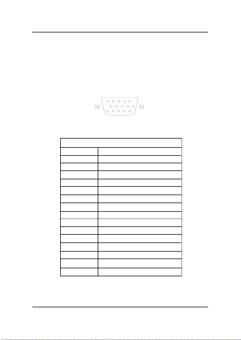
2.12 DB 15 Pin Connector
The mainboard provides a DB 15-pin connector to connect to a VGA
monitor.
5
10
15
1
6
11
Analog Video Display Connector(DB15-S)
Pin Signal Description
1 Red
2 Green
3 Blue
4 Not used
5 Ground
6 Ground
7 Ground
8 Ground
9 Not used
10 Ground
1 1 Not used
12 SDA
13 Horizontal Sync
1 4 Vertical Sync
15 SCL
2-16
Page 22
CHAPTER 2 HARDWARE INSTALLATION
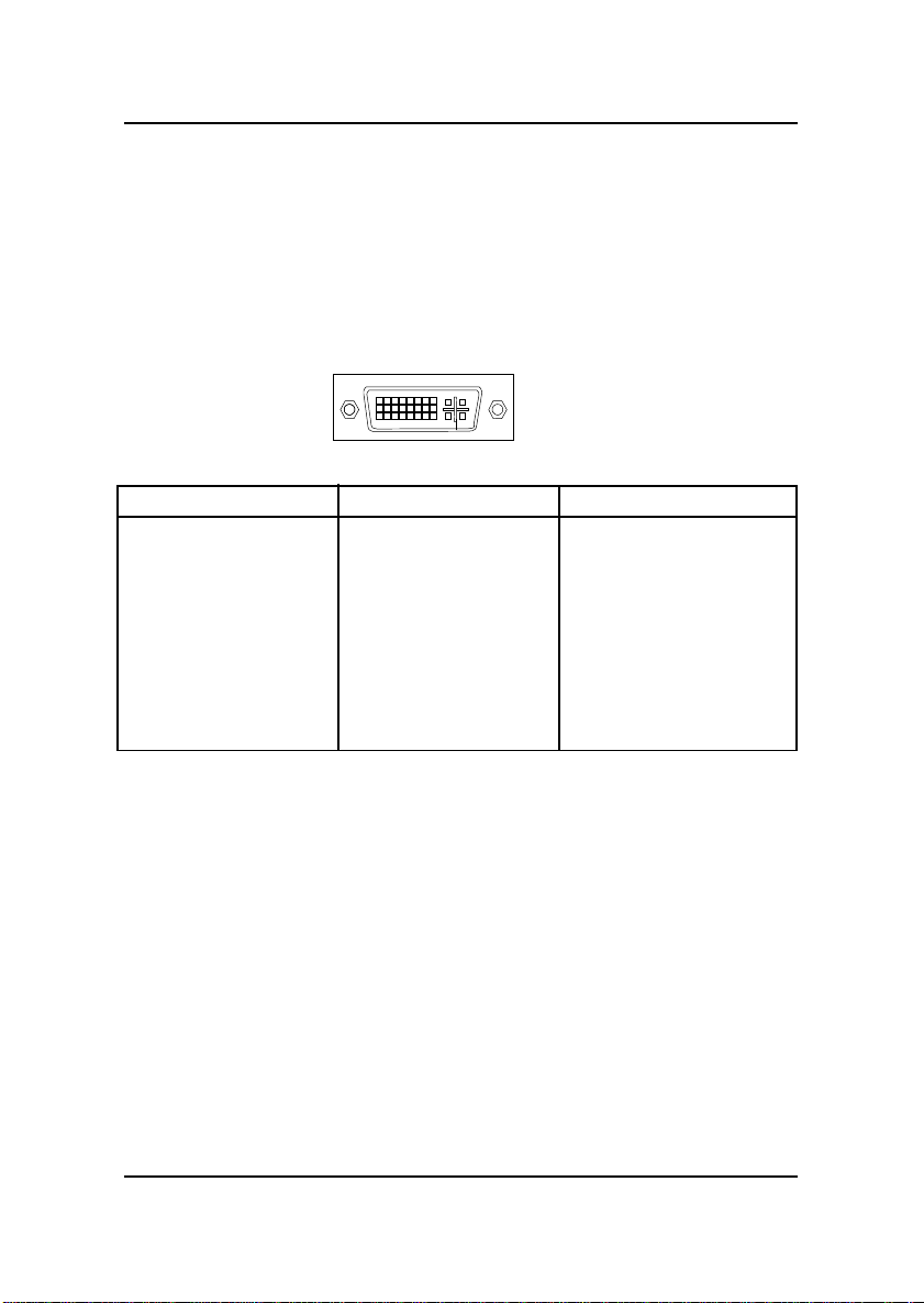
2.13 DVI Connector
The mechanical interconnect includes 29 signals contacts, which are divided
into two sections. The first section is organized as three rows of eight
contacts. The second section contains five signals that are designed
specifically for analog implementations.
18
9
Pin Signal Pin Signal Pin Signal
1 T.M.D.S. Data 2- 9 T.M.D.S. Data 1- 17 T.M.D.S. Data 02 T.M.D.S. Data 2+ 10 T.M.D.S. Data 1+ 18 T.M.D.S. Data 0+
3 T.M.D.S. Data 2/4 Shield 11 T.M.D.S. Data 1/3 Shield 19 T.M.D.S. Data 0/5 Shield
4 T.M.D.S. Data 4- 12 T.M.D.S. Data 3- 20 T.M.D.S. Data 55 T.M.D.S. Data 4+ 13 T.M.D.S. Data 3+ 21 T.M.D.S. Data 5+
6 DDC Clock 14 +5V Power 22 T.M.D.S. Data Clock Shield
7 DDC Data 15 Ground 23 T.M.D.S. Clock+
8 Analog Vertical Sync 16 Hot Plug Detect 24 T.M.D.S. ClockC1 Analog Red C2 Analog Green C3 Analog Blue
C4 Analog Horizontal Sync C5 Analog Ground
C1 C2
16
C3
17
C4
24
C5
2-17
Page 23
CHAPTER 2 HARDWARE INSTALLATION
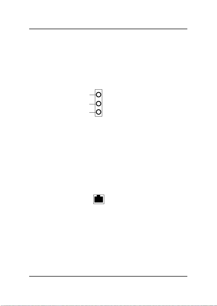
2.14 Audio Port Connectors
Line Out is a connector for Speakers or Headphones. Line In is used for
external CD player, T ape layer , or other audio devices. Mic is a connector for
the microphones.
Mic
Line In
Line Out
1/8” Stereo Audio Connectors
2.15 Modem Connector
The mainboard provides a RJ-11 connector for your modem need.
RJ-11
Connector
2-18
Page 24
CHAPTER 2 HARDWARE INSTALLATION
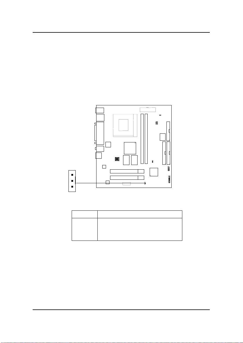
2.16 Wake-Up on LAN Connector: JWOL1
The JWOL1 connector is for use with LAN add-on cards that supports
Wake Up on LAN function. To use this function, you need to set the
“W ake-Up on LAN” to enable at the BIOS Power Management Setup.
3
1
JWOL1
PIN SIGNAL
1 5VSB
2 GND
3 MP_WAKEUP
Note: LAN wake-up signal is active “high”.
Note: To be able to use this function, you need a power supply that
provide enough power for this feature. (Power supply with 750ma
5V Stand-by)
2-19
Page 25
CHAPTER 2 HARDWARE INSTALLATION
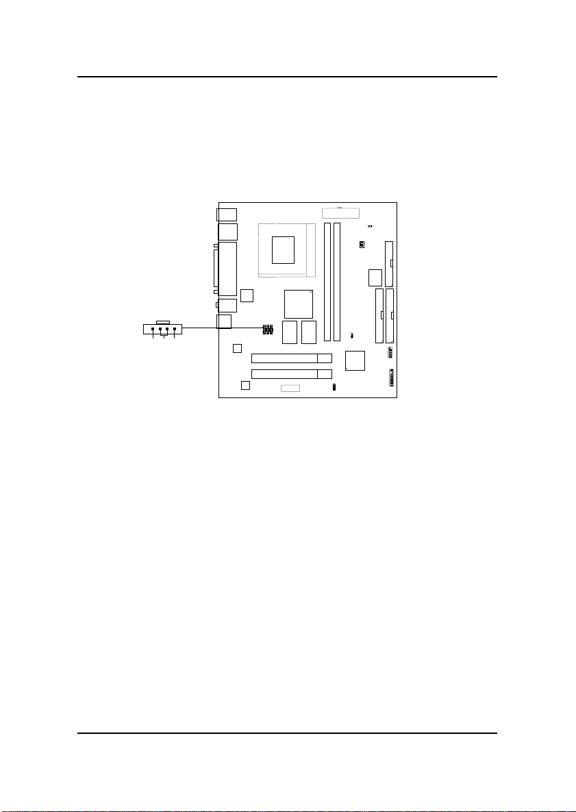
2.17 Modem-In: JTAD1
The connector is for Modem with internal voice connector.
Mono_Out
GND
Phone_In
JTAD1
Mono_Out is connected to the Modem Speaker Out connector.
Phone_In is connected to the Modem Microphone In connector.
2-20
Page 26
CHAPTER 2 HARDWARE INSTALLATION
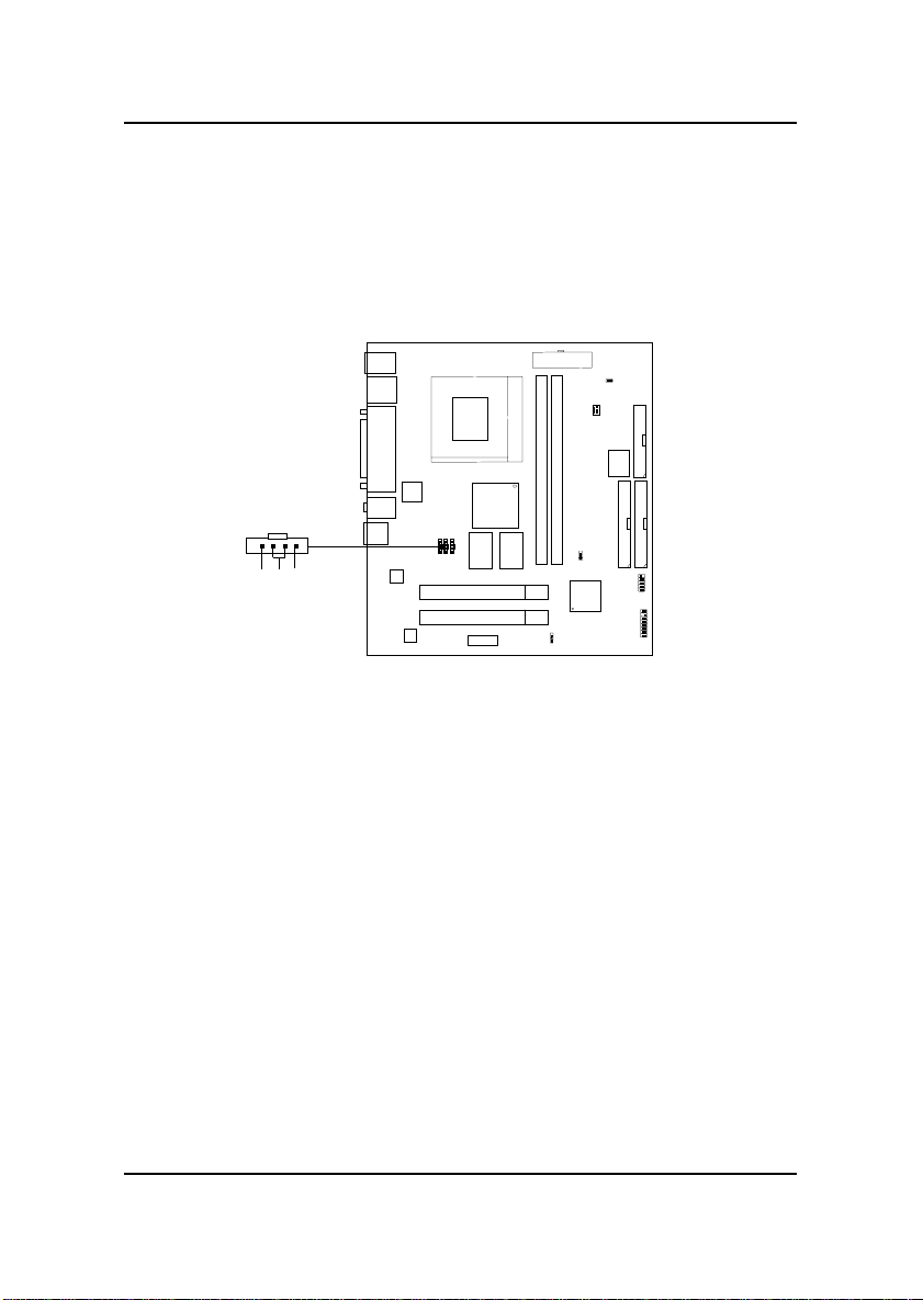
2.18 AUX Line In Connector: Video
This connector is used for DVD Add on Card with Line In connector.
R GND L
Video
2-21
Page 27
CHAPTER 2 HARDWARE INSTALLATION
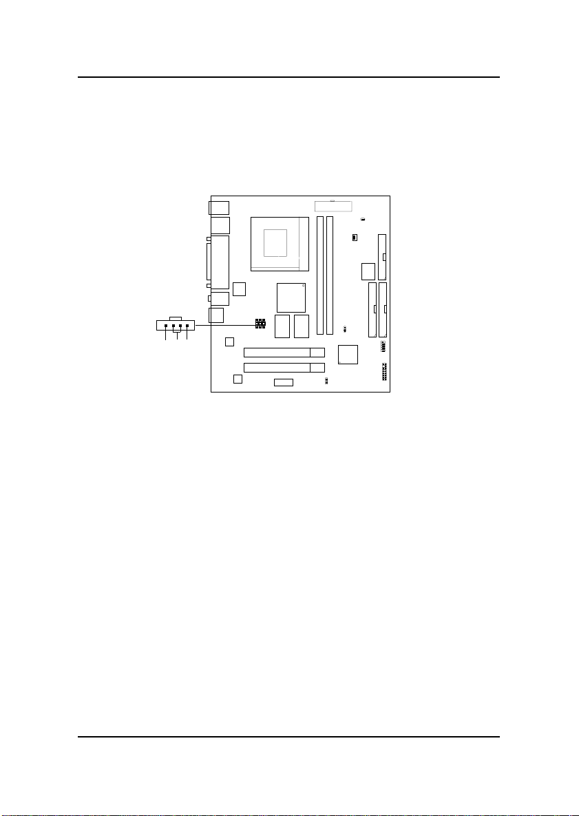
2.19 CD-In Connector: CD-IN
This connector is for CD-ROM audio connector.
LGNDR
CD_In
2-22
Page 28
CHAPTER 2 HARDWARE INSTALLATION
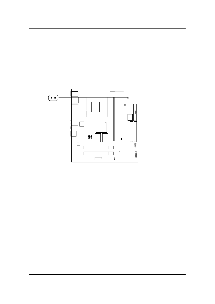
2.20 Chassis Intrusion Switch Case: JCASE
(optional)
This connector is connected to a 2-pin connector chassis switch. If the
Chassis is open, the switch will be open. The system will record this status.
T o clear the warning, you must enter the BIOS settting and clear the status.
JCASE
2-23
Page 29
CHAPTER 2 HARDWARE INSTALLATION
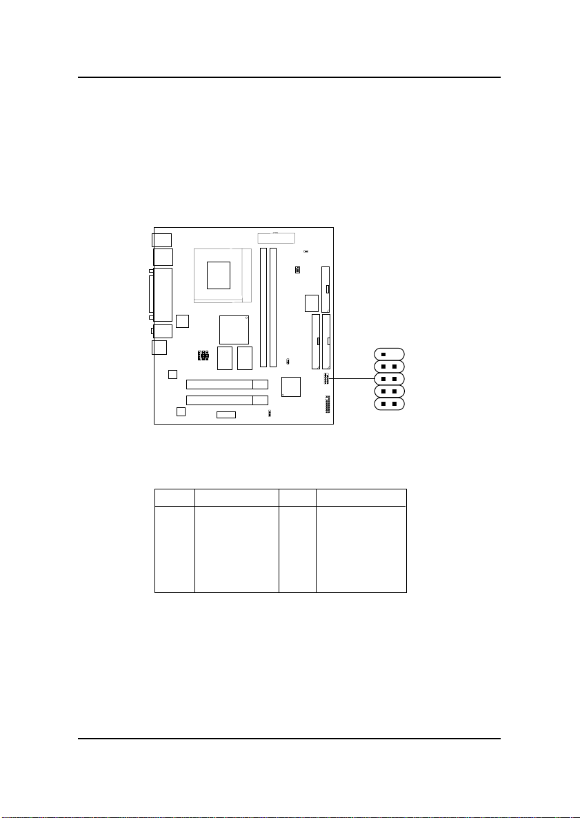
2.31 USB Front Connector: JGUSB1
The mainboard provides a front Universal Serial Bus connector. This is an
optional USB connector for Front Panel.
9
1
JGUSB1
Pin Description Pin Description
1 VCC 6 Data1+
2 VCC 7 GND
3 Data0- 8 GND
4 Data1- 9 GND
5 Data0+ 10 NC
10
2
2-24
 Loading...