

Page 1

CHAPTER 1 INTRODUCTION
1-1
The MS-6182 A TX WH8 mainboard is a high-performance
computer mainboard based on Intel® 810 chipset. The MS-6182 is designed
for the Intel® Pentium® II/III or CeleronTM processor for inexpensive
business/personal desktop markets.
The Intel® 810 chipset is the first generation Integrated Graphics
chipset for the Intel® Pentium® II/III CeleronTM processor . The graphics
accelerator architecture consists of dedicated multi-media engines executing
in parallel to deliver high performance 3D, 2D, and motion compensation
video capabilities. An integrated centralized memory arbiter allocates
memory bandwidth to multiple system agents to optimize system memory
utilization. A new chipset component interconnect, the hub interface, is
designed into the Intel® 810 chipset to provide an efficient communication
channel between the memory controller hub and I/O hub controller .
The Intel® 810 chipset contains three core components: the
Graphics and Memory Controller Hub (GMCH), the I/O Controller Hub
(ICHO/ICH) and the Firmware Hub (FWH). The GMCH integrates a 66/
100MHz, P6 family system bus controller, 2D/3D graphics accelerator ,
100MHz SDRAM controller and high-speed hub interface for communication
with the ICHO/ICH. The ICHO/ICH integrates an Ultra A T A/33(ICHO) or
Ultra A T A/66(ICH) controller , USB host controller , LPC interface controller,
FWH interface conroller, PCI interface controller , AC’97 digital controller and
a hub interface for communication with the GMCH.
The Intel® 82802 Firmware Hub (FWH) component is part of the
Intel® 810 chipset. The FWH is key to enabling future security and
manageability infrastructure for the PC platform.
Chapter 1
INTRODUCTION
Page 2

CHAPTER 1 INTRODUCTION
1-2
1.1 Mainboard Features
CPU
l Slot 1 for Intel® Pentium® II/Pentium® III/CeleronTM processor.
l Supports 233MHz, 266MHz, 300MHz, 333MHz, 350MHz, 400MHz,
450MHz, 500MHz and faster processor .
Chipset
l Intel® 810 (GMCH) chipset. (421 BGA)
- Integrated Graphics Controller
- Intel DDM Architecture
- SDRAM memory Independent of System Bus
l Intel® ICH/ICH0 chipset. (241 BGA)
- AC’97 Controller Integrated
- 2 full IDE channels, up to AT A66
- 2 full IDE channels, up to AT A33 (ICH0 only)
- Low pin count interface for SIO
Front Side Bus (FSB)
l 66/100MHz clocks are supported.
Main Memory
l Support three 168-pin DIMM sockets.
l Support a maximum memory size of 256MB(64-bit) or 512MB(128-bit)
SDRAM.
Slots
l One AMR(Audio Modem Riser) and one PTI(PanelLink TV-Out Interface)
l Six 32-bit PCI Bus slots and one 16-bit ISA slot (wherein one PCI/ISA slot
is shared).
l Support 3.3v/5v PCI bus Interface.
Page 3

CHAPTER 1 INTRODUCTION
1-3
On-Board IDE
l An IDE controller on the ICH chipset provides IDE HDD/CD-ROM with
PIO, Bus Master and Ultra DMA/66 operation modes.
l Can connect up to four IDE devices.
On-Board Peripherals
l On-Board Peripherals include:
- 1 floppy port supports 2 FDD with 360K, 720K, 1.2M, 1.44M and
2.88Mbytes.
- 2 serial port (COMA + COMB)
- 1 parallel port supports SPP/EPP/ECP mode
- 2 USB ports and 2 USB connectors
- 1 IrDA connector for SIR.
- 1 VGA port
Video
l GMCH chip integrated
l 2D/3D Graphics
l Onboard 4MB Display Cache (optional)
Audio
l ICH/ICH0 chip integrated
l Creative® ES1373 (optional)
- Running on PCI BUS.
- Support Direct Sound and Direct Sound 3D
- AC97’ Compliant
BIOS
l The mainboard BIOS provides “Plug & Play” BIOS which detects the
peripheral devices and expansion cards of the board automatically.
l The mainboard provides a Desktop Management Interface(DMI) function
which records your mainboard specifications.
l Adjustable FSB CPU core voltage.
Page 4

CHAPTER 1 INTRODUCTION
1-4
Dimension
l A TX Form Factor: 30.5(L)x19.2(W)x4 layers PCB
Mounting
l 8 mounting holes.
System Hardware Monitor
l CPU/Power Supply/Chassis Fan Revolution Detect
l CPU Fan Control (the fan will automatically stop when the system enters
suspend mode)
l System Voltage Detect
l CPU Overheat W arning.
l Display Actual Current Voltage
Other Features
l Keyboard Password Wake-Up (reserved)
l LAN W ake-Up
l Internal/External Modem W ake-Up
l Suspend to RAM (STR)
Page 5
CHAPTER 1 INTRODUCTION
1-5
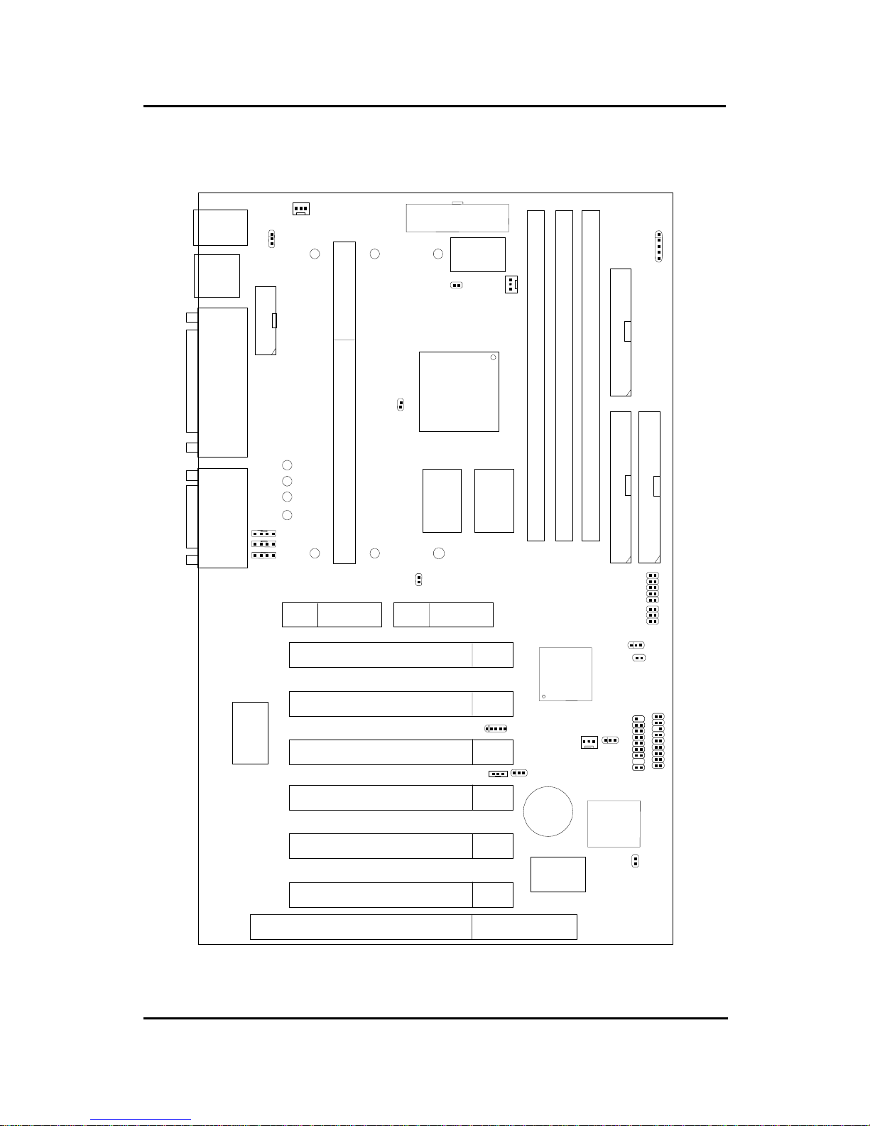
1.2 Mainboard Layout
MS-6182 A TX WH8 Mainboard
PCI SLOT 3
PCI SLOT 2
PCI SLOT 1
ATX
Power Supply
Intel
®
810
Chipset
(GMCH)
SLOT 1
DIMM 2
Top: mouse
Bottom:
keyboard
Top: Port 1
USB
DIMM 3
IDE2
Bottom:
Port 2
IDE1
FDD
Intel
®
ICH0/ICH
JMDM1
Creative
ES1373
JFP1
JGS1
JGL1
JBAT1
JWOL1
Diagnostic LED
MDM_IN
AUX_IN
COM B
CPUFAN
BATT
+
Top: LPT
Bottom:
COM A
VGA Port
Top: Midi/
Game Port
Bottom:
Line-Out
Line-In
Mic
CD_IN
SDRAM SDRAM
J2
J16
SYSFAN
J15
PCI SLOT 4
PCI SLOT 5
PCI SLOT 6
J17
USB2
AMR
PTI
IR
JKBV1
DIMM 1
FWH
JP3
ISA SLOT
J10
J3
PSFAN
W83627HF-AW
W83628F
 Loading...