

Page 1

CHAPTER 1 INTRODUCTION
1-1
The MS-6178 Micro A TX WH5 mainboard is a high-performance computer
mainboard based on Intel® 810 (810/810 DC100/810e) chipset. The MS-6178
is designed for the Intel® Pentium II/III or CeleronTM processor for inexpensive business/personal desktop markets.
The Intel® 810 chipset is the first generation Integrated Graphics chipset for
the Intel® CeleronTM processor . The graphics accelerator architecture
consists of dedicated multi-media engines executing in parallel to deliver
high performance 3D, 2D, and motion compensation video capabilities. An
integrated centralized memory arbiter allocates memory bandwidth to
multiple system agents to optimize system memory utilization. A new
chipset component interconnect, the hub interface, is designed into the Intel
810 chipset to provide an efficient communication channel between the
memory controller hub and I/O hub controller.
The series of Intel® 810 chipset contains three core components: the
Graphics and Memory Controller Hub (GMCH), the I/O Controller Hub (ICH)
and the Firmware Hub (FWH). The GMCH integrates a 66/100MHz for 810
and 810 DC100 and 66/100/133 MHz for 810e, P6 family system bus controller, 2D/3D graphics accelerator , 100MHz SDRAM controller and high-speed
hub interface for communication with the ICH. The ICH integrates an Ultra
A T A 33(ICHO)/66(ICH) controller , USB host controller, LPC interface
controller, FWH interface conroller , PCI interface controller, AC’97 digital
controller and a hub interface for communication.
The Intel® 82802 Firmware Hub (FWH) component is part of the seried of
Intel® 810 chipset. The FWH is key to enabling future security and manage-
ability infrastructure for the PC platform.
Chapter 1
INTRODUCTION
Page 2
CHAPTER 2 HARDWARE INSTALLATION
2-1
CPU
CPU
Chapter 2
HARDWARE INSTALLATION
2.1 Central Processing Unit: CPU
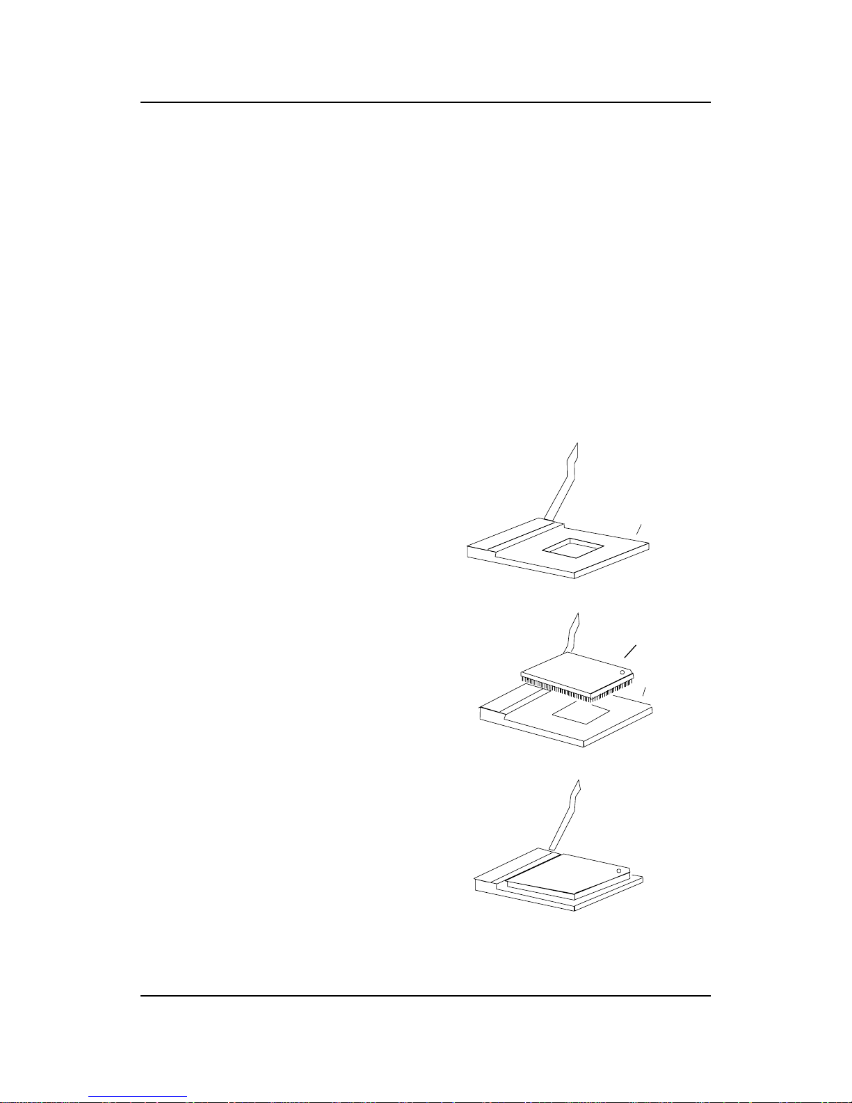
The mainboard operates with Intel® CeleronTM processor. The mainboard
uses a CPU socket called Socket 370 for easy CPU installation. The CPU
should always have a Heat Sink and a cooling fan attached to prevent
overheating.
3. Press the lever down to
complete the installation.
2 . Locate Pin 1 in the socket
and look for the white dot or
cut edge in the CPU. Match
Pin 1 with the white dot/cut
edge. Then, insert the CPU.
It should insert easily.
Open Lever
Pin 1
Sliding
Plate
White dot/
Cut edge
Close
Lever
1 . Pull the lever sideways away
from the socket. Then, raise
the lever up to a 90-degree
angle.
Pin 1
2.1-1 CPU Installation Procedures
Page 3

CHAPTER 3 AWARD® BIOS SETUP
3-1
Chapter 3
AWARD® BIOS SETUP
Award® BIOS ROM has a built-in Setup program that allows users to modify
the basic system configuration. This type of information is stored in
battery-backed RAM (CMOS RAM), so that it retains the Setup information
when the power is turned off.
Page 4

CHAPTER 4
AMI® BIOS USERS GUIDE
4-1
Chapter 4
AMI® BIOS USER’S GUIDE
The system configuration information and chipset register information is
stored in the CMOS RAM. This information is retained by a battery when
the power is off. Enter the BIOS setup (if needed) to modify this information.
The following pages will describe how to enter BIOS setup, and all about
options.
Page 5

CHAPTER 4
AMI® BIOS USERS GUIDE
4-2
2 . When the “Hit <DEL>” message appears, press <DEL> key to
enter the BIOS setup screen.
3 . After pressing <DEL> key, the BIOS setup screen will appear .
AMIBIOS (C) 1999 American Megatrends Inc.
AGIOMS VXXX XXXXXX
Hit <DEL> if you want to run setup
(C) American Megatrends Inc.
61-XXXX-001169-00111111-071592-i82440FX-H
4.1 Enter BIOS Setup
Enter the AMI® setup Program’s Main Menu as follows:
1. Turn on or reboot the system. The following screen appears with
a series of diagnostic check.
Note: If you don’t want to modify CMOS original setting, then don’t press any
key during the system boot.
Page 6

CHAPTER 4
AMI® BIOS USERS GUIDE
4-3
Standard CMOS Setup
Advanced CMOS Setup
Advanced Chipset Setup
Power Management Setup
PCI/Plug and Play Setup
Peripheral Setup
Hardware Monitor Setup
Auto-Detect Hard Disks
Change User Password
Change Supervisor Password
Change Language Setting
Auto Configuration with Optimal Settings
Auto Configuration with Fail Safe Settings
Save Settings and Exit
Exit without Saving
4 . Use the <Up> and <Down> key to move the highlight scroll up or
down.
5 . Use the <ENTER> key to select the option.
6 . T o exit, press <ESC>. T o save and exit, press <F10>.
7 . Section 3.2 to 3.7 will explain the option in more details.
AMIBIOS HIFLEX SETUP UTILITIES - VERSION 1.22
(C) 1999 American Megatrends, Inc. All Rights
Reserved
Standard CMOS setup for changing time, hard disk type, etc.
Page 7

CHAPTER 4
AMI® BIOS USERS GUIDE
4-4
2. Use <Up> and <Down> to choose the item and <PgUp> and
<PgDn> keys to modify the highlighted item.
3. After you have finished with the Standard CMOS Setup, press
<ESC> to go back to the main menu.
4.2 Standard CMOS Setup
1 . Press <ENTER> on “Standard CMOS Setup” of the main menu
screen .
AMIBIOS SETUP - STANDARD CMOS SETUP
(C)1999 American Megatrends,Inc.All Rights Reserved
Date (mm/dd/yyyy): Fri March 20, 1999
Time (hh/mm/ss): 17:09:25
Floppy Drive A: 1.44 MB 3 1/2
Floppy Drive B: Not Installed
LBA Blk PIO 32Bit
Type Size Cyln Head WPcom Sec Mode Mode Mode Mode
Pri Master :Auto ON ON AUTO ON
Pri Slave :Auto ON ON AUTO ON
Sec Master :Auto ON ON AUTO ON
Sec Slave :Auto ON ON AUTO ON
Boot Sector Virus Protection Disabled
ESC:Exit :Sel
PgUp/PgDn:Modify
F2/F3:Color
Month : Jan-Dec
Day : 01-31
Year : 1901-2099
Page 8

CHAPTER 4
AMI® BIOS USERS GUIDE
4-5
2. Use <Up> and <Down> to choose the item and <PgUp> and
<PgDn> keys to modify the highlighted item.
3. After you have finished with the Advanced CMOS Setup, press
<ESC> to go back to the main menu.
Quick Boot Enabled
Ist Boot Device Floppy
2nd Boot Device IDE 0
3rd Boot Device CD-ROM
Try Other Boot Devices Yes
Initial Display Mode BIOS
Display Mode at Add-On ROM Init Force-BIOS
Floppy Access Control Read-Write
S.M.A.R.T. For Hard Disk Disabled
BootUp Num-Lock On
Floppy Drive Swap Disabled
Floppy Drive Seek Disabled
PS/2 Mouse Support Enabled
Primary Display VGA/EGA
Password Check Setup
Boot to OS/2 > 64M No
CPU Serial Number Disabled
Cache Bus ECC Enabled
System BIOS Cacheable Disabled
C000, 64k Shadow Enabled
ESC:Exit :Sel
PgUp/PgDn:Modify
F2/F3:Color
4.3 Advanced CMOS Setup
1 . Press <ENTER> on “Advanced CMOS Setup” of the main menu
AMIBIOS SETUP - ADVANCED CMOS SETUP
(C) 1999 American Megatrends, Inc. All Rights Reserved
Available Options:
Disabled
Enabled
Page 9

CHAPTER 4
AMI® BIOS USERS GUIDE
4-6
Description of the item on screen follows:
Quick Boot
Set this option to Enabled to permit AMI® BIOS to boot within 5
seconds. This option replaces the old ABOVE 1 MB Memory T est option.
The Optimal default setting is Enabled. The Fail-Safe default setting is
Disabled.
1st Boot Device/2nd Boot Device/3rd Boot Device
This option sets the sequence of boot drives.
The settings are:
IDE0 The system will boot from the first HDD.
IDE1 The system will boot from the Second HDD.
IDE2 The system will boot from the Third HDD.
IDE3 The system will boot from the Fourth HDD.
F(optical) The system will boot from LS-120(120M Floppy).
SCSI The system will boot from the SCSI.
Network The system will boot from the Network drive.
CD-ROM The system will boot from the CD-ROM.
Disable Disable this sequence.
Try other Boot Devices
This option sets the device boot, if all the Four Boot Devices failed.
Initial Display Mode
This option sets the device boot, if all the Four Boot Devices failed.
Display Mode at Add-On ROM Init
This option sets the device boot, if all the Four Boot Devices failed.
Floppy Access Control
This option sets the Floppy to Read-only or Read-Write.
S.M.A.R.T. for Hard Disks
This option sets the SMART Function for the hard disk. The hard
disk need to have SMAR T function for this feature to work.
Page 10

CHAPTER 4
AMI® BIOS USERS GUIDE
4-7
Boot up Num Lock
When this option is set to Off, AMI® BIOS turns off the Num Lock
key when the system is powered on. The end user can then use the arrow
keys on both the numeric keypad and the keyboard. The settings are On or
Off. The optimal default and Fail-Safe default settings are On.
Floppy Drive Swap
Set this option to Enabled to specify that floppy drives A: and B: are
swapped. The setting are Enabled and Disabled. The Optimal and Fail-Safe
default settings are Disabled.
Floppy Drive Seek
When this option is set to Enabled, AMI® BIOS performs a Seek
command on floppy drive A: before booting the system. The settings are
Enabled and Disabled. The Optimal and Fail-Safe default settings are
Disabled.
PS/2® Mouse Support
When this option is set to Enabled, AMI® BIOS supports a PS/2
®
mouse. The settings are Enabled and Disabled. The Optimal and Fail-Safe
default settings are Enabled.
Primary Display
This option configures the primary display subsytem in the computer.
The settings are Mono(monochrome), 40CGA, 80CGA or VGA/EGA. The
optimal and Fail-Safe default settings are VGA/EGA.
Password Check
This option specifies the type of AMI® BIOS password protection
that is implemented. The Optimal and Fail-Safe default settings are Setup.
Boot To OS/2® > 64MB
Set this option to Enabled to permit the BIOS to run properly , if OS/
2® is to be used with > 64MB of DRAM. The settings are Enabled or
Disabled. The Optimal and Fail-safe default settings are Disabled.
Page 11

CHAPTER 4
AMI® BIOS USERS GUIDE
4-8
CPU Serial Number
This option is for Pentium III processor . During Enabled, this will
check the CPU Serial number. Disabled this option if you don’ t want the
system to know the Serial number.
Cache Bus ECC
This option is for Pentium® II processor . During Enabled, this will
affect the system performance. Disabled this option if you don’t want to
affect the system performance.
System BIOS Cacheable
AMI® BIOS always copies the system BIOS from ROM to RAM for
faster execution. Set this option to Enabled to permit the contents of the
F0000h RAM memory segment to be written to and read from cache memory .
The settings are Enabled or Disabled. The Optimal default setting is Enabled. The Fail-Safe default setting is Disabled.
C000, 64K Shadow
These options specify how the contents of the video ROM are
handled. The settings are:
Disabled -the V ideo ROM is not copied to RAM.
Cached - the contents of the video ROM from C0000h - C7FFFh are
not only copied from ROM to RAM; it can also be written
to or read from cache memory .
Shadow - the Contents of the video ROM from C0000h - C7FFFh are
copied(shadowed) from ROM to RAM for faster execution.
The Optimal and Fail-Safe default setting is Cached.
Page 12

CHAPTER 4
AMI® BIOS USERS GUIDE
4-9
4.4 Advanced Chipset Setup
1 . Press <ENTER> on “Advanced Chipset Setup” of the main menu
screen.
AMIBIOS SETUP - ADVANCED CHIPSET SETUP
(C) 1999 American Megatrends, Inc. All Rights Reserved
USB Function Enabled
USB Keyboard Legacy Support Disabled
CPU Latency Timer Disabled
DRAM Page Closing Policy Closed
CD Hole (DC000h - DFFFh) Disabled
Memory Hole Disabled
DRAM Tras/Trc Cycle Time(SCLKs) 6/8
Address Setup Time(SCLKs) 1
CAS# Latency(SCLKs) 3
SDRAM RAS# to CAS# Delay(SCLKs) 3
SDRAM RAS# Precharge 3
Graphics Mode Select UMA 1MB
Onboard Video Chip Enabled
CPU BIST Enable Disabled
ICH Delayed Transaction Disabled
ICH DCB Enable Disabled
****Display Cache Function****
Initialize Display Cache Memory Enabled
Paging Mode Control Closed
RAS-to-CAS Default
Available Options:
Disabled
Enabled
ESC:Exit :Sel
PgUp/PgDn:Modify
F2/F3:Color
2. Use <Up> and <Down> to choose the item and <PgUp> and
<PgDn> keys to modify the highlighted item.
3. After you have finished with the Advanced Chipset Setup, press
<ESC> to go back to the main menu.
CAS Latency Slow
RAS Timing Slow
RAS Precharge Timing Slow
Page 13

CHAPTER 4
AMI® BIOS USERS GUIDE
4-10
Description of the item on screen follows:
USB Function
Set this option to Enabled or Disabled the on-chip USB controller.
The Optional and Fail-Safe default settings are Disabled.
USB Keyboard Legacy Support
Set this option to Enabled or Disabled USB keyboard.
The Optional and Fail-Safe default settings are Disabled.
DRAM Page Closing Policy
This option controls whether the GMCH will precharge bank or
precharge all, during the service of a page miss.
Memory Hole
This option allows the end user to specify the location of a memory
hole. The cycle matching the selected memory hole will be passed to the
ISA bus. If Enabled, the selected hole is not remapped.
DRAM Tras/Trc Cycle Time (SCLKs)
This option controls the number of SCLKs for an access cycle.
CAS# Latency
This option determines the CAS latency time parameter of SDRAM.
The settings are 2 clks or 3 clks. Under 66MHz CPU bus, set this option to
either 2 or 3 but for 100MHz CPU, it is recommended that this be set to 3.
SDRAM RAS# to CAS# Delay
This operation decide the delay in assertion of CAS#(SCAS#) from
assertion of RAS#(SRAS#) in 66MHz. Under 66MHz CPU bus, set this
option to either 2 or 3 but for 100MHz CPU, it is recommended that this be
set to 3.
Page 14

CHAPTER 4
AMI® BIOS USERS GUIDE
4-11
SDRAM RAS Precharge
This option defines the RAS# precharge requirements for the
SDRAM memory type in 66MHz clocks. Under 66MHz CPU bus, set this
option to either 2 or 3 but for 100MHz CPU, it is recommended that this be
set to 3.
Graphics Mode Select
This option is used to enable/Disable the internal graphics device
and select the amount of system memory that is used to support the internal
graphics device.
Onboard Video Chip
This option is used to enable/disabled the video onboard the chip.
Initialize Display Cache Memory
This option will allow you to initialized the display cache memory .
Paging Mode Control
This option decide the GMCH memory controller tends to leave
pages open or closed.
RAS-to-CAS
This option determine the display cache RAS#-toCAS# delay .
CAS# Latency
This option decide the display cache CAS latency.
RAS# Timing
This option controls RAS# active to precharge, and refresh to RAS#
active delay .
RAS# Precharge Timing
This option controls RAS# precharge clocks.
Page 15

CHAPTER 4
AMI® BIOS USERS GUIDE
4-12
4.5 Power Management Setup
1 . Press <ENTER> on “Power Management Setup” of the main menu
screen.
2. Use <Up> and <Down> to choose the item and <PgUp> and
<PgDn> keys to modify the highlighted item.
3. After you have finished with the Power Management Setup, press
<ESC> to go back to the main menu.
ACPI Standby State S1
Power Management/APM Enabled
Green PC LED Status Blinking
Green PC Monitor Power State Stand By
Video Power Down Mode Suspend
Hard Disk power Down Mode Stand By
Standby Time Out (Minute) Disabled
Suspend Time Out (Minute) Disabled
Throttle Slow Clock Ratio 50.0%
Keyboard & PS/2 Mouse Access Monitor
FDC/LPT/COM Ports Access Monitor
SB & MSS Audio Ports Access Ignore
Midi Ports Access Ignore
ADLIB Ports Access Ignore
Primary Master IDE Access Monitor
Primary Slave IDE Access Ignore
Secondary Master IDE Access Monitor
Secondary Slave IDE Access Ignore
PIRQ[A] IRQ Active Ignore
PIRQ[B] IRQ Active Ignore
PIRQ[C] IRQ Active Ignore
PIRQ[D] IRQ Active Ignore
System Thermal Ignore
Thermal Slow Clock Ratio 50.0%
CPU Critical Temperature 650C/1490F
Power Button Function On/Off
Restore on AC/Power Loss Last State
Ring Resume from Soft Off Disabled
LAN Resume from Soft Off Disabled
PME Function Support Disabled
ESC:Exit :Sel
PgUp/PgDn:Modify
F2/F3:Color
AMIBIOS SETUP - POWER MANAGEMENT SETUP
(C) 1999 American Megatrends, Inc. All Rights Reserved
Available Options:
Disabled
Enabled
RTC Alarm Resume from Soft Off Disabled
RTC Alarm Date 15
RTC Alarm Hour 12
RTC ALarm Minute 30
RTC Alarm Second 30
Page 16

CHAPTER 4
AMI® BIOS USERS GUIDE
4-13
Description of the item on screen follows:
ACPI Standby State
This option sets the ACPI Power Management Standby State.
S1 Sleeping State
The S1 sleeping state is low wake-up latency sleeping state. In this
state, no system context is lost(CPU or chip set) and hardware
maintains all system context.
S3 Sleeping State
The S3 state is a low wake-up latency sleeping sate where all system
context is lost expect system memory . CPU, cache, and chipset
context are lost in this state. Hardware maintains memory context and
restores some CPU and L2 configuration context.
Power Management/APM
Set this option to Enabled to enable the chipset’s power management
features and APM(Advanced Power Management). The settings are
Enabled, Inst-On(instant-on) or Disabled. The Optimal and Fail-Safe default
settings are Disabled.
Green PC LED Status
This option specifies the power state that the green PC-compliant
video monitor enters when AMI® BIOS places it in a power savings state
after the specified period of display inactivity has expired. The settings are
Off, Standby , Suspend or Disabled. The Optimal and Fail-Safe default
settings are Standby.
Green PC Monitor Power State
This option specifies the power state that the green PC-compliant
video monitor enters when AMI® BIOS places it in a power savings state
after the specified period of display inactivity has expired. The settings are
Off, Standby , Suspend or Disabled. The Optimal and Fail-Safe default
settings are Standby.
Page 17

CHAPTER 4
AMI® BIOS USERS GUIDE
4-14
Video Power Down Mode
This option specifies the power conserving state that the VESA VGA
video subsystem enters after the specified period of display inactivity has
expired. The settings are Disabled, Standby or Suspend. The Optimal and
Fail-Safe default settings are Standby .
Hard Disk Power Down Mode
This option specifies the power conserving state that the hard disk
drive enters after the specified period of hard drive inactivity has expired.
The settings are Disabled, Standby or Suspend. The Optimal and Fail-Safe
default settings are Disabled.
Standby Time Out (Minute)
This option specifies the length of a period of system inactivity while
in Standby state. When this length of time expires, the computer enters
Suspend power state. The settings are Disabled, 1 min, 2 min, 3 min, 4 min, 5
min, 6 min, 7 min, 8 min, 9 min, 10 min, 11 min, 12 min, 13 min, 14 min or 15
min. The Optimal and Fail-Safe default settings are Disabled.
Suspend Time Out (Minute)
This option specifies the length of a period of system inactivity while
in Suspend state. When this length of time expires, the computer enters
Suspend power state. The settings are Disabled, 1 min, 2 min, 3 min, 4 min, 5
min, 6 min, 7 min, 8 min, 9 min, 10 min, 11 min, 12 min, 13 min, 14 min or 15
min. The Optimal and Fail-Safe default settings are Disabled.
Throttle Slow Clock Ratio
This option specifies the speed at which the system clock runs in
power saving states. The settings are expressed as a ratio between the
normal CPU clock speed and the CPU clock speed when the computer is in
the power-conserving state.
Thermal Slow Clock Ratio
When set to Monitor, then you can choose the throttle ratio. This
option is connected with the CPU Critical T emperature Option.
Page 18

CHAPTER 4
AMI® BIOS USERS GUIDE
4-15
CPU Critical Temperature
This option is for setting the CPU temperature that would be critical
enough, so that it would use the Thermal Slow Clock Ratio to cool down the
CPU.
Power Button Function
During Suspend, if you push the switch once, the system goes into
suspend mode and if you push it more than 4 seconds, the system will be
turned off. During On/Off, the system will turn off once you push the
switch.
Restore on AC/Power Loss
The settings are power on or last status. During power on, after
every AC power loss, the system will be turned on. During last status, after
every AC power loss, whatever the system status, it will be the same when
the AC power returns.
Note: a. If you set this option to last status, the Power Button Function
must be set to On/Off, or this function will not work.
b. Jumper JP1 must always be open, for this function to work properly .
Ring Resume from Soft-Off
During Disabled, the system will ignore any incoming call from the
modem. During Enabled, the system will boot up if there’s an incoming call
from the modem.
Note: If you have change the setting, you must let the system boot up until
it goes to the operating system. Then, power off the system. This
function will work the next time you power on.
Page 19

CHAPTER 4
AMI® BIOS USERS GUIDE
4-16
LAN Resume from Soft-Off
During Disabled, the system will ignore any incoming signal from the
LAN network card. During Enabled, the system will boot up if there’s an
incoming signal from the LAN network card.
Note: If you have change the setting, you must let the system boot up until
it goes to the operating system. Then, power off the system. This
function will work the next time you power on.
RTC Alarm Resume From Soft-Off
This function is for setting the Date, Hour, Minute, and Second for
your computer to boot up. During Disabled, you cannot use this function.
During Enabled, Choose the Date, Hour, Minute, and Second:
RTC Alarm Date Choose which day the system will boot up.
RTC Alarm Hour Choose which hour the system will boot up.
RTC Alarm Minute Choose which minute the system will boot up.
RTC Alarm Second Choose which second the system will boot up.
Note: If you have change the setting, you must let the system boot up until
it goes to the operating system. Then, power off the system. This
function will work the next time you power on.
Page 20

CHAPTER 4
AMI® BIOS USERS GUIDE
4-17
4.6 PCI/Plug and Play Setup
1 . Press <ENTER> on “PCI/Plug and Play Setup” of the main menu
screen.
2. Use <Up> and <Down> to choose the item and <PgUp> and
<PgDn> keys to modify the highlighted item.
3. After you have finished with the PCI/Plug and Play Setup, press
<ESC> to go back to the main menu.
Plug and Play Aware O/S No
Clear NVRAM No
PCI Latency Timer (PCI Clocks) 64
Primary Graphics Adapter Add-On VGA
PCI VGA Palette Snoop Disabled
DMA Channel 0 Pn P
DMA Channel 1 Pn P
DMA Channel 3 Pn P
DMA Channel 5 Pn P
DMA Channel 6 Pn P
DMA Channel 7 Pn P
IRQ3 PCI/PnP
IRQ4 PCI/PnP
IRQ5 PCI/PnP
IRQ7 PCI/PnP
IRQ9 PCI/PnP
IRQ10 PCI/PnP
IRQ11 PCI/PnP
IRQ14 PCI/PnP
IRQ15 PCI/PnP
ESC:Exit :Sel
PgUp/PgDn:Modify
F2/F3:Color
AMIBIOS SETUP - PCI/PLUG AND PLAY SETUP
(C) 1999 American Megatrends, Inc. All Rights Reserved
Available Options:
Enabled
Disabled
Page 21

CHAPTER 4
AMI® BIOS USERS GUIDE
4-18
Description of the item on screen follows:
Plug and Play Aware O/S
Set this option to Yes if the operating system in this computer is
aware of and follows the Plug and Play specification. Currently , only
Windows® 95 is PnP-aware. The settings are Yes or No. The Optimal and
Fail-Safe default settings No.
Clear NVRAM on Every Boot
During Y es, this will clear NVRAM data on every boot.
PCI Latency Timer (PCI Clocks)
This option specifies the latency timings (in PCI clocks) for all PCI
devices on the PCI bus. The settings are 32, 64, 96, 128, 160, 192, 224 or 248.
The Optimal and Fail-Safe default settings are 64.
Primary Graphics Adapter
This option is for selecting which VGA card is to be your primary
display graphics adapter.
PCI VGA Palette Snoop
When this option is set to Enabled, multiple VGA devices operating
on different buses can handle data from the CPU on each set of palette
registers on every video device. Bit 5 of the command register in the PCI
device configuration space is the VGA Palette Snoop bit (0 is disabled). For
example, if there are two VGA devices in the computer (one PCI and ISA)
and the Bit settings are:
Disabled - Data read and written by the CPU is only directed to the
PCI VGA device’ s palette registers.
Enabled - Data read and written by the CPU is directed to
both the PCI VGA device’ s palette registers and the
ISA VGA device palette registers, permitting the
palette registers of both devices to be identical.
This option must be set to Enabled if an ISA adapter card requires
VGA palette snooping. The settings are Enabled or Disabled. The Optimal
and Fail-Safe default settings are Disabled.
Page 22

CHAPTER 4
AMI® BIOS USERS GUIDE
4-19
DMA Channel 0/1/3/5/6/7
These options specify the bus that the specified DMA channel is
used. These options allow you to reserve DMAs for legacy ISA adapter
cards.
These options determine if AMI® BIOS should remove a DMA from
the available DMAs passed to devices that are configurable by the system
BIOS. The available DMA pool is determined by reading the ESCD
NVRAM. If more DMAs must be removed from the pool, the end user can
use these options to reserve the DMA by assigning an ISA/EISA setting to
it.
IRQ3/IRQ4/IRQ5/RQ7/IRQ9/IRQ10/IRQ11/IRQ14/IRQ15
These options specify the bus that the specified IRQ line is used on.
These options allow you to reserve IRQs for legacy ISA adapter cards.
These options determine if AMI® BIOS should remove an IRQ from
the pool of available IRQs passed to devices that are configurable by the
system BIOS. The available IRQ pool is determined by reading the ESCD
NVRAM. If more IRQs must be removed from the pool, the end user can use
these options to reserve the IRQ by assigning an ISA/EISA setting to it.
Onboard I/O is configured by AMI® BIOS. All IRQs used by onboard I/O
are configured as PCI/PnP . If all IRQs are set to ISA/EISA and IRQ14 and 15
are allocated to the onboard PCI IDE, IRQ9 will still be available for PCI and
PnP devices, because at least one IRQ must be available for PCI and PnP
devices. The settings are ISA/EISA or PCI/PnP . The Optimal and Fail-Safe
default settings are IRQ3 through 7 are ISA/EISA. The Optimal and Fail-Safe
default settings PCI/PnP.
Page 23

CHAPTER 4
AMI® BIOS USERS GUIDE
4-20
4.7 Peripheral Setup
1 . Press <ENTER> on “Peripheral Setup” of the main menu screen.
2. Use <up> and <down> to choose the item and <PgUp> and
<PgDn> keys to modify the highlighted item.
3 . After you have finished with the Peripheral Setup, press <ESC> to
go back to the main menu.
AMIBIOS SETUP - PERIPHERAL SETUP
(C) 1999 American Megatrends, Inc. All Rights Reserved
CLKGEN Spread Spectrum Enabled
CPU Ratio Selection 3.0x
CPU Host Clock (Mhz) Auto
Onboard Sound Enabled
Onboard AC’97 Audio Enabled
Onboard AC’97 Modem Disabled
Onboard IDE Both
Onboard FDC Auto
Onboard Serial Port A Auto
Onboard Serial Port B Auto
Serial Port B Mode Normal
IR Duplex Mode Half Duplex
IR Pin Select IRRX/IRTX
Onboard CIR Port Disabled
CIR IRQ Select 10
Onboard Parallel Port Auto
Parallel Port Mode ECP
EPP Version N/ A
Parallel Port IRQ Auto
Parallel Port DMA Channel Auto
Onboard Midi Port Disabled
Midi IRQ Select 9
Onboard Game Port Disabled
Mouse PowerOn Function Disabled
Keyboard PowerOn Function Disabled
Specific Key for Power On N/A
Available Options:
Auto
Disabled
Enabled
ESC:Exit :Sel
PgUp/PgDn:Modify
F2/F3:Color
Page 24

CHAPTER 4
AMI® BIOS USERS GUIDE
4-21
Description of the item on screen follows:
CLKGEN Spread Spectrum
This item allows you to set the CPU clock generator spread spectrum.
CPU Ratio Selection
This item allows you to set the CPU ratio.
CPU Host Clock (MHz)
This item allows you to set the CPU host clock.
Onboard Sound
This item allows you to enable/disable the onboard Aureal audio
chipset. The settings are Enabled, Disabled.
Onboard AC’97 Audio/Onboard AC’97 Modem
This item allows you to decide to enable/disable the 810 chipset
family to support AC97 Audio/Modem. The settings are Enabled, Disabled.
Onboard IDE
Set this option to enable or disable on board IDE controller .
Page 25
CHAPTER 4
AMI® BIOS USERS GUIDE
4-22
Onboard FDC
Choose Auto, for the BIOS to automatically detect the device
Choose Enabled, Enabling onboard FDC.
Choose Disabled, Disabling onboard FDC.
The Optimal and Fail-Safe default settings are Auto.
Onboard Serial Port A/Onboard Serial Port B
Choose 3F8, for the BIOS to automatically detect the device.
If the ISA add-on card has Onboard FDC to be set at
FDC exist
none FDC exist
Disabled
Enabled
üüüüDISABLED X DISABLED X
üüX X COM3 4 COM4 3
XXüü COM1 4 COM2 3
ü XXü COM2 3 COM3 4
X üüX COM1 4 COM4 3
üüüX COM4 3 DISABLED X
üüX ü COM3 4 DISABLED X
ü X üü COM2 3 DISABLED X
X üüüCOM1 4 DISABLED X
X X X X COM1 4 COM2 3
ü X X X COM2 3 COM3 4
X ü X X COM1 4 COM3 4
XXü X COM1 4 COM2 3
XXXü COM1 4 COM2 3
If the ISA add-on card has Onboard Serial port to be set at
COM1
(I/O:3F8H)
COM2
(I/O:3F8H)
COM3
(I/O:3E8H)
COM4
(I/O:2E8H)
PORT1
PORT2
IRQ
ASSIGNED
IRQ
ASSIGNED
Note: If the onboard serial port interrupt and ISA add-on card interrupt are in
conflict, the serial port will not work properly. Please disable one of the
devices.
Page 26

CHAPTER 4
AMI® BIOS USERS GUIDE
4-23
Serial PortB Mode
Choosing Normal will set the Serial Port B for normal use, not for IR
device. Choosing IrDA or Ask IR will set it for use with IR device using
these protocols.
IR Duplex Mode
Can be set as either Half or Full duplex.
IR Pin Select
Set this option to IRRX/IRTX when using an internal IR device
which is connected to IR1 connector.
Onboard Parallel Port
Choose Auto, the BIOS automatically assigned onboard parallel port
to the available parallel port or disabled.
If the ISA add-on card has Onboard parallel port to be set as
üüüDisabled X
üüX LPT3 5
ü X ü LPT2 5
X üü LPT1 7
ü X X LPT2 5
X ü X LPT1 7
XXü LPT1 7
X X X LPT1 7
LPT1
I/O:378H
LPT2
I/O:278H
LPT3
I/O:3BCH
POR T
ASSIGNED
IRQ
ASSIGNED
Note: If the onboard parallel port interrupt and ISA add-on card interrupt are
in conflict, the parallel port will not work properly. Please disable one of
the devices.
Page 27

CHAPTER 4
AMI® BIOS USERS GUIDE
4-24
Parallel Port Mode
This option allows user to choose the operating mode of the onbaord
parallel port. The settings are Normal, SPP/EPP or ECP mode.
EPP Version
This option is for setting which EPP version will be used. The
settings are 1.7 and 1.9.
Parallel Port IRQ
If the onboard parallel mode is not on auto mode, the user can select
the interrupt line for onboard parallel port. We suggest that the user select
the interrupt for the onboard parallel port as shown below:
Parallel Port DMA Channel
This option allows user to choose DMA channel 1 to 3 for the
onboard parallel port on ECP mode.
Onboard parallel port set at
Parallel Port IRQ
LPT1(378H)
LPT2(278H)
LPT3(3BCH)
7
5
5
Page 28

CHAPTER 4
AMI® BIOS USERS GUIDE
4-25
4.8 Hardware Monitor Setup (optional)
The Hardware Monitor Setup is used to set the CPU speed and
monitor the current CPU T emperature, CPU Fan speed, Chassis Fan
Speed, Power fan speed, Vcore, etc.
1 . Press <ENTER> on “Hardware Monitor Setup” of the main menu
screen.
AMIBIOS SETUP - HARDWARE MONITOR SETUP
(C) 1999 American Megatrends, Inc. All Rights Reserved
Chassis Intrusion Disabled
CPU Temperature Detected By CPU
CPU Temperature 460C/1140F
System Temperature 31oC/87oF
CPU Fan Speed 4560 RPM
CPU VID 2.00V
Vcore 1.936V
Vtt 2.480V
Vio 3.280V
+5,000V 5.113V
+12,000V 12.045V
-12,000V -11.763V
-5,000V -4.932V
Battery 3.00V
+5V SB 5.60V
Available Options:
Manual
Auto
ESC:Exit :Sel
PgUp/PgDn:Modify
F2/F3:Color
2. Use <Up> and <Down> to choose the item and <PgUp> and
<PgDn> keys to modify the highlighted item.
3. After you have finished with the PCI/Plug and Play Setup, press
<ESC> to go back to the main menu.
Page 29

CHAPTER 3 AWARD® BIOS SETUP
3-2
3.1 Entering Setup
Power on the computer and press <Del> immediately to allow you to
enter Setup. The other way to enter Setup is to power on the computer.
When the below message appears briefly at the bottom of the screen during
the POST (Power On Self T est), press <Del> key or simultaneously press
<Ctrl>, <Alt>, and <Esc> keys.
TO ENTER SETUP BEFORE BOOT , PRESS <CTRL-AL T-ESC>
OR <DEL> KEY
If the message disappears before you respond and you still wish to
enter Setup, restart the system to try again by turning it OFF then ON or
pressing the “RESET” button on the system case. You may also restart by
simultaneously pressing <Ctrl>, <Alt>, and <Delete> keys. If you do not
press the keys at the correct time and the system does not boot, an error
message will be displayed and you will again be asked to,
PRESS <F1> TO CONTINUE, <CTRL-AL T-ESC>
OR <DEL> TO ENTER SETUP
3.2 Getting Help
Main Menu
The on-line description of the highlighted setup function is displayed
at the bottom of the screen.
Status Page Setup Menu/Option Page Setup Menu
Press F1 to pop up a small help window that describes the appropri-
ate keys to use and the possible selections for the highlighted item. To exit
the Help Window, press <Esc>.
Page 30

CHAPTER 3 AWARD® BIOS SETUP
3-3
STANDARD CMOS Feature
Advanced BIOS Feature
Advanced Chipset Feature
Integrated Peripherals
Power Management Setup
PnP/PCI Configurations
PC Health Status
Frequency/Voltage Control
Load Fail-Safe Defaults
Load Optimized Defaults
Set Supervisor Password
Set User Password
Save & Exit Setup
Exit Without Saving
Esc : Quit
F10 : Save & Exit Setup
Time, Date, Hard Disk Type...
↑ ↓ → ← : Select Item
(Shift)F2 : Change Color
Standard CMOS Setup
Use this Menu for basic system configurations.
Advanced BIOS Features
Use this menu to set the Advanced Features available on your
system.
3.3 The Main Menu
Once you enter A ward® BIOS CMOS Setup Utility , the Main Menu (Figure 1)
will appear on the screen. The Main Menu allows you to select from twelve
setup functions and two exit choices. Use arrow keys to select among the
items and press <Enter> to accept or enter the sub-menu.
CMOS Setup Utility - Copyright(C) 1984-1999
Page 31

CHAPTER 3 AWARD® BIOS SETUP
3-4
Advanced Chipset Features
Use this menu to change the values in the chipset registers and
optimize your system’s performance.
Integrated Peripherals
Use this menu to specify your settings for integrated peripherals.
Power Management Setup
Use this menu to specify your settings for power management.
PnP/PCI Configuration
This entry appears if your system supports PnP/PCI.
PC Health Status (Optional)
This entry shows your PC health status.
Frequency/Voltage Control
Use this menu to specify your settings for frequency/voltage control.
Load Fail-Safe Defaults
Use this menu to load the BIOS default values for the minimal/stable
performance for your system to operate.
Load Optimized Defaults
Use this menu to load the BIOS default values that are factory
settings for optimal performance system operations.
Supervisor/User Password
Use this menu to set User and Supervisor Passwords.
Save & Exit Setup
Save CMOS value changes to CMOS and exit setup.
Exit Without Saving
Abandon all CMOS value changes and exit setup.
Page 32

CHAPTER 3 AWARD® BIOS SETUP
3-5
Date(mm:dd:yy): Fri, Feb 28,1999
Time(hh:mm:ss): 00:00:00
IDE Primary Master Press Enter 2557MB
IDE Primary Slave Press Enter None
IDE Secondary Master Press Enter None
IDE Secondary Slave Press Enter None
Drive A 1.44M, 3.5in.
Drive B None
Video EGA/VGA
Halt On All Errors
Based Memory 640K
Extended Memory 64512K
Total Memory 65536K
3.4 Standard CMOS Setup
The items in Standard CMOS Setup Menu are divided into 10 catego-
ries. Each category includes no, one or more than one setup items. Use the
arrow keys to highlight the item and then use the <PgUp> or <PgDn> keys
to select the value you want in each item.
Item Help
Menu Level >
↑ ↓ → ← Move Enter:Select +/-/PU/PD:Value F10:Save ESC:Exit F1:General Help
F5:Previous Values F6:Fail-safe defaults F7:Optimized Defaults
CMOS Setup Utility - Copyright(C) 1984-1999 Award Software
Standard CMOS Setup
Page 33

CHAPTER 3 AWARD® BIOS SETUP
3-6
Date
The date format is <day><month> <date> <year>.
Day Day of the week, from Sun to Sat, determined by
BIOS. Read-only .
month The month from Jan. through Dec.
date The date from 1 to 31 can be keyed by numeric
function keys.
year The year, depends on the year of the BIOS
Time
The time format is <hour> <minute> <second>.
PrimaryMaster/PrimarySlave
SecondaryMaster/Secondary Slave
Press PgUp/<+> or PgDn/<-> to select Manual, None, Auto type.
Note that the specifications of your drive must match with the drive table.
The hard disk will not work properly if you enter improper information for
this category. If your hard disk drive type is not matched or listed, you can
use Manual to define your own drive type manually .
If you select Manual, related information is asked to be entered to the
following items. Enter the information directly from the keyboard. This
information should be provided in the documentation from your hard disk
vendor or the system manufacturer.
Page 34

CHAPTER 3 AWARD® BIOS SETUP
3-7
If the controller of HDD interface is SCSI, the selection shall be
“None”.
If the controller of HDD interface is CD-ROM, the selection shall be
“None”.
Access Mode The settings are Auto, Normal, Large,LBA.
Cylinder number of cylinders
Head number of heads
Precomp write precom
Landing Zone landing zone
Sector number of sectors
Page 35

CHAPTER 3 AWARD® BIOS SETUP
3-8
Anti-Virus Protection
Allows you to choose the VIRUS W arning feature for IDE
Hard Disk boot sector protection. If this function is enabled and
someone attempt to write data into this area, BIOS will show a
warning message on screen and alarm beep.
Disable(default) No warning message to appear when
anything attempts to access the boot
sector or hard disk partition table.
Enable Activates automatically when the
system boots up causing a warning
message to appear when anything
attempts to access the boot sector of
hard disk partition table.
3.5 Advanced BIOS Features
Anti-Virus Protection Disabled
CPU Internal Cache Enabled
External Cache Enabled
CPU L2 Cache ECC Checking Enabled
Quick Power On Self Test Disabled
First Boot device Floppy
Second Boot device HDD-0
Third Boot device LS/Zip
Boot other device Enabled
Swap Floppy Drive Disabled
Boot Up Floppy Seek Disabled
Boot Up Numlock Status O ff
Gate A20 Option Fast
Typematic Rate Setting Disabled
Typematic Rate (Chars/Sec) 6
Typematic Delay (Msec) 250
Security Option Setup
OS Select for DRAM > 64MB Non-OS2
Report No FDD for Win 95 No
Item Help
Menu Level >
↑ ↓ → ← Move Enter:Select +/-/PU/PD:Value F10:Save ESC:Exit F1:General Help
F5:Previous Values F6:Fail-safe defaults F7:Optimized Defaults
CMOS Setup Utility - Copyright(C) 1984-1999 Award Software
Advanced BIOS Features
Page 36

CHAPTER 3 AWARD® BIOS SETUP
3-9
CPU Internal Cache
The default value is Enabled.
Enabled (default) Enable cache
Disabled Disable cache
Note: The internal cache is built in the processor .
External Cache
Choose Enabled or Disabled. This option enables the level 2 cache
memory .
CPU L2 Cache ECC Checking
Choose Enabled or Disabled. This option enables the level 2 cache
memory ECC(error check correction).
Quick Power On Self Test
This category speeds up Power On Self T est (POST) after you power
on the computer. If this is set to Enabled, BIOS will shorten or skip some
check items during POST .
Enabled Enable quick POST
Disabled (default) Normal POST
First/Second/Third/Other Boot Device
The BIOS attempts to load the operating system from the devices in
the sequence selected in these items. The settings are Floppy , LS/ZIP, HDD0/HDD-1/HDD-2/HDD-3, SCSI, CDROM, LAN, and Disabled.
Swap Floppy Drive
Switches the floppy disk drives between being designated as A and
B. Default is Disabled.
Boot Up Floppy Seek
During POST , BIOS will determine if the floppy disk drive installed is
40 or 80 tracks. 360K type is 40 tracks while 760K, 1.2M and 1.44M are all 80
tracks.
Page 37

CHAPTER 3 AWARD® BIOS SETUP
3-10
Boot Up NumLock Status
The default value is On.
On (default) Keypad is numeric keys.
Off Keypad is arrow keys.
Gate A20 Option
Normal The A20 signal is controlled by keyboard
controller or chipset hardware.
Fast(default) The A20 signal is controlled by port 92 or
chipset specific method.
Typematic Rate Setting
Key strokes repeat at a rate determined by the keyboard controller.
When enabled, the typematic rate and typematic delay can be selected.
The settings are: Enabled/Disabled.
Typematic Rate (Chars/Sec)
Sets the number of times a second to repeat a key stroke when you
hold the key down. The settings are: 6, 8, 10, 12, 15, 20, 24, 30.
Typematic Delay (Msec)
Sets the delay time after the key is held down before it begins to
repeat the keystroke The settings are: 250, 500, 750, 1000.
Security Option
This category allows you to limit access to the system and Setup, or
just to Setup.
System The system will not boot and access to Setup
will be denied if the correct password is not
entered at the prompt.
Setup(default)The system will boot, but access to Setup will
be denied if the correct password is not entered
at the prompt.
Page 38

CHAPTER 3 AWARD® BIOS SETUP
3-11
OS Selection for DRAM > 64MB
Allows OS2® to be used with > 64 MB of DRAM. Settings are NonOS/2 (default) and OS2. Set to OS/2 if using more than 64MB and running
OS/2®.
Report No FDD For Win 95
Whether report no FDD for Win 95 or not. The settings are: Yes, No.
Page 39

CHAPTER 3 AWARD® BIOS SETUP
3-12
Note: Change these settings only if you are familiar with the chipset.
3.6 Advanced Chipset Features
The Advanced Chipset Features Setup option is used to change the
values of the chipset registers. These registers control most of the system
options in the computer.
Choose the “ADV ANCED CHIPSET FEATURES” from the Main
Menu and the following screen will appear .
SDRAM CAS Latency Time 3
SDRAM Cycle Time Tras/Trc 6/8
SDRAM RAS-to-CAS Delay 1
SDRAM RAS Precharge Time 3
System BIOS Cacheable Disabled
Video BIOS Cacheable Disabled
Memory Hole at 15M-16M Disabled
CPU Latency Timer Disabled
Delayed Transaction Disabled
On-Chip Video Enabled
Local Memory Frequency 100MHz
*Onboard Display Cache Setting*
Initial Display Cache Enable
CAS# Latency 3
Paging Mode Control Open
RAS-to-CAS Override by CAS#LT
RAS# Timing Fast
RAS# Precharge Timing Fast
Item Help
Menu Level >
↑ ↓ → ← Move Enter:Select +/-/PU/PD:Value F10:Save ESC:Exit F1:General Help
F5:Previous Values F6:Fail-safe defaults F7:Optimized Defaults
CMOS Setup Utility - Copyright(C) 1984-1999 Award Software
Advanced Chipset Features
Page 40

CHAPTER 3 AWARD® BIOS SETUP
3-13
SDRAM CAS latency Time
When synchronous DRAM is installed, the number of clock cycles
of CAS latency depends on the DRAM timing. The settings are: 2 and 3.
SDRAM Cycle Time Tras/Trc
Select the number of SCLKs for an access cycle. The settings are: 5/7
and 6/8.
SDRAM RAS-to-CAS Delay
This field lets you insert a timing delay between the CAS and RAS
strobe signals, used when DRAM is written to, read from, or refreshed. Fast
gives faster performance; and Slow gives more stable performance. This
field applies only when synchronous DRAM is installed in the system.
The settings are: 2 and 3.
SDRAM RAS Precharge Time
If an insufficient number of cycles is allowed for the RAS to accumulate its charge before DRAM refresh, the refresh may be incomplete and the
DRAM may fail to retain data. Fast gives faster performance; and Slow
gives more stable performance. This field applies only when synchronous
DRAM is installed in the system. The settings are: 2 and 3.
System BIOS Cacheable
Selecting Enabled allows caching of the system BIOS ROM at
F0000h-FFFFFh, resulting in better system performance. However, if any
program writes to this memory area, a system error may result. The settings
are: Enabled and Disabled.
Page 41

CHAPTER 3 AWARD® BIOS SETUP
3-14
Video BIOS Cacheable
Select Enabled allows caching of the video BIOS , resulting in better
system performance. However, if any program writes to this memory area, a
system error may result. The settings are: Enabled and Disabled.
Memory Hole At 15M-16M
You can reserve this area of system memory for ISA adapter ROM.
When this area is reserved, it cannot be cached. The user information of
peripherals that need to use this area of system memory usually discusses
their memory requirements. The settings are: Enabled and Disabled.
CPU Latency Timer
During Enabled, A deferrable CPU cycle will only be Deferred after it
has been in a Snoop Stall for 31 clocks and another ADS# has arrived.
During Disabled, A deferrable CPU cycle will be Deferred immediately after
the GMCH receives another ADS#.
Delayed Transaction
The chipset has an embedded 32-bit posted write buffer to support
delay transactions cycles. Select Enabled to support compliance with PCI
specification version 2.1. The settings are: Enabled and Disabled.
On-Chip Video
This option enabled/disabled the on-chip video window size for VGA
driver use. The settings are: Enabled, Disabled.
Local Memory Frequency (For Intel 810E chipset only)
Select the Onboard Display Cache frequency . The settings are:
133MHz or 100MHz.
Page 42

CHAPTER 3 AWARD® BIOS SETUP
3-15
Onboard Display Cache Setting (optional)
Initial Display Cache
Enable and Disable Onboard Display Cache. The settings are:
Enable and Disable.
CAS# Latency
The number of clock cycles of CAS# Latency depends on the
Onboard Display cache timing. The settings are: 2 and 3.
Paging Mode Control
Select the paging mode control. The settings are:Open and Close.
RAS-to-CAS Override
This items allows you to insert a timing delay between the CAS and
RAS strobe signals, used when Onboard display cache is written to, read
from, or refreshed. During by CAS# LT, this will depend on the Onboard
Display Cache CAS# Latency setting. During Override (2), RAS-to-CAS
time= 2.
RAS# Timing
This option controls RAS# active to Precharge, and refresh to RAS#
active delay (in local memory clocks).
Slow RAS# to precharge (t
RAS
) =7, refresh to RAS# act (tRC) = 10
Fast RAS# to precharge (t
RAS
) =5, refresh to RAS# act (tRC) = 8
RAS# Precharge Timing
This item controls RAS# precharge (in local memory clocks)
Slow RAS# Precharge Time=3
Fast RAS# Precharge Time=2
Page 43

CHAPTER 3 AWARD® BIOS SETUP
3-16
3.7 Integrated Peripherals
OnChip Primary PCI IDE Enabled
OnChip Secondary PCI IDE Enabled
IDE Primary Master PIO Auto
IDE Primary Slave PIO Auto
IDE Secondary Master PIO Auto
IDE Secondary Slave PIO Auto
IDE Primary Master UDMA Auto
IDE Primary Slave UDMA Auto
IDE Secondary Master UDMA Auto
IDE Secondary Slave UDMA Auto
USB Controller Enabled
USB Keyboard Support Disabled
Init Display First PCI Slot
AC97 Audio Disabled
AC97 Modem Enabled
Onboard Audio Device Enabled
IDE HDD Block Mode Enabled
Power On Function
KB Power On Password
Hot Key Power On
Onboard FDC Controller Enabled
Onboard Serial Port 1 3F8/IRQ4
Onboard Serial Port 2 2F8/IRQ3
Item Help
Menu Level >
↑ ↓ → ← Move Enter:Select +/-/PU/PD:Value F10:Save ESC:Exit F1:General Help
F5:Previous Values F6:Fail-safe defaults F7:Optimized Defaults
CMOS Setup Utility - Copyright(C) 1984-1999 Award Software
Integrated Peripherals
UART Mode Select Normal
RxD, TxD Active Hi, Lo
IR Transmition Delay Enabled
UR2 Duplex Mode Half
USE IR Pins IR-Rx2Tx2
Onboard Parallel Port 378/IRQ7
Parallel Port Mode SPP
EPP Mode Select EPP 1.7
ECP Mode use UDMA 3
PWRON After PWR-Fail Off
Game Port Address Disabled
Midi Port Address Disabled
Midi Port IRQ 5
Power Status LED Blinking
OnChip Primary/Secondary PCI IDE
The integrated peripheral controller contains an IDE interface
with support for two IDE channels. Select Enabled to activate each
channel separately . The settings are: Enabled and Disabled.
Page 44

CHAPTER 3 AWARD® BIOS SETUP
3-17
IDE Primary/Secondary Master/Slave PIO
The four IDE PIO (Programmed Input/Output) fields let you set a PIO
mode (0-4) for each of the four IDE devices that the onboard IDE interface
supports. Modes 0 through 4 provide successively increased performance.
In Auto mode, the system automatically determines the best mode for each
device. The settings are: Auto, Mode 0, Mode 1, Mode 2, Mode 3, Mode 4.
IDE Primary/Secondary Master/Slave UDMA
Ultra DMA/33 implementation is possible only if your IDE hard drive
supports it and the operating environment includes a DMA driver (Windows
95 OSR2 or a third-party IDE bus master driver). If your hard drive and your
system software both support Ultra DMA/33 and Ultra DMA/66, select
Auto to enable BIOS support. The settings are: Auto, Disabled.
USB Controller
Select Enabled if your system contains a Universal Serial Bus (USB)
controller and you have USB peripherals. The settings are: Enabled,
Disabled.
USB Keyboard Support
Select Enabled if your system contains a Universal Serial Bus (USB)
controller and you have a USB keyboard. The settings are: Enabled,
Disabled.
Init Display First
This item allows you to decide to activate whether PCI Slot or onchip VGA first. The settings are: PCI Slot, Onboard.
AC97 Audio/Modem
This item allows you to decide to enable/disable the 810 chipset
family to support AC97 Audio/Modem. The settings are: Enabled, Disabled.
Onboard Audio Device (For Aureal Vortex 8810 onboard only)
This item allows you to enable/disable the Onboard Aureal audio
chipset. The settings are: Enabled, Disabled.
Page 45

CHAPTER 3 AWARD® BIOS SETUP
3-18
IDE HDD Block Mode
Block mode is also called block transfer, multiple commands, or
multiple sector read/write. If your IDE hard drive supports block mode (most
new drives do), select Enabled for automatic detection of the optimal number
of block read/writes per sector the drive can support. The settings are:
Enabled, Disabled.
Power On Function
This function allows you to select the item to power on the system.
The settings are : Button Only, Mouse Left, Mouse Right, Password,
Hotkey , keyboard 98.
Onboard FDC Controller
Select Enabled if your system has a floppy disk controller (FDD)
installed on the system board and you wish to use it. If you install add-on
FDC or the system has no floppy drive, select Disabled in this field.
The settings are: Enabled and Disabled.
Onboard Serial Port 1/Port 2
Select an address and corresponding interrupt for the first and
second serial ports. The settings are: 3F8/IRQ4, 2E8/IRQ3, 3E8/IRQ4, 2F8/
IRQ3, Disabled, Auto.
UART Mode Select
This item allows you to determine which InfraRed(IR) function of the
onboard I/O chip, this functions uses.
Page 46

CHAPTER 3 AWARD® BIOS SETUP
3-19
Onboard Parallel Port
Disabled There is a built-in parallel port on the
on-board Super I/O chipset that provides Standard, ECP, and EPP features.
It has the following options:
Disable
3BCH/IRQ7 Line Printer port 0
278H/IRQ5 Line Printer port 2
378H/IRQ7 Line Printer port 1
Onboard Parallel Mode
SPP : Standard Parallel Port
EPP : Enhanced Parallel Port
ECP : Extended Capability Port
To operate the onboard parallel port as
Standard Parallel Port only , choose
“SPP.” T o operate the onboard parallel
port in the EPP modes simultaneously ,
choose “EPP.” By choosing “ECP”, the
onboard parallel port will operate in ECP
mode only . Choosing “ECP + EPP” will
allow the onboard parallel port to
support both the ECP and EPP modes
simultaneously . The ECP mode has to
use the DMA channel, so choose the
onboard parallel port with the ECP
feature. After selecting it, the following
message will appear: “ECP Mode Use
DMA” At this time, the user can
choose between DMA
(3BCH/IRQ7)/
(278H/IRQ5)/
(378H/IRQ7)
SPP/EPP/ECP/
ECP+EPP
Page 47

CHAPTER 3 AWARD® BIOS SETUP
3-20
PWRON After PWR-FAIL
This option will determine how the system will power on after a
power failure.
Game Port Address/Midi Port Address
This will determine which Address the Game Port/Midi Port will use.
Power Status LED
This item determines which state the Power LED will use. The
settings are Blinking, Dual, and Single. During blinking, the power LED will
blink when the system enters the suspend mode. When the mode is in Dual,
the power LED will change its color. Choose the single and the power LED
will always remain lit.
channels 3 or 1. The onboard parallel
port is EPP Spec. compliant, so after the
user chooses the onboard parallel port
with the EPP function, the following
message will be displayed on the
screen: “EPP Mode Select.” At this
time either EPP 1.7 spec. or EPP 1.9 spec.
can be chosen.
Page 48

CHAPTER 3 AWARD® BIOS SETUP
3-21
3.8 Power Management Setup
The Power Management Setup allows you to configure you system
to most effectively save energy while operating in a manner consistent with
your own style of computer use.
ACPI Suspend Type S1(POS)
Power Management User Define
Video Off Method DPMS
Video Off In Suspend Y es
Suspend Type Stop Grant
Modem Use IRQ 3
Suspend Mode Disabled
HDD Power Down Disabled
Soft-Off by PWR-BTTN Instant-Off
Wake-Up by PCI Card Disabled
Power On by Ring Disabled
Wake-Up on LAN Disabled
USB KB Wake-Up from S3 Disabled
CPU Thermal-Throtting 62.57%
Resume By Alarm Disabled
Date(of Month) Alarm 0
Date(hh:mm:ss) 0 0 0
**Reload Global Timer Events**
Primary IDE 0 Disabled
Primary IDE 1 Disabled
Secondary IDE 0 Disabled
Secondary IDE 1 Disabled
FDD, COM, LPT Port Disabled
PCI PIRQ[A-D]# Disabled
Item Help
Menu Level >
↑ ↓ → ← Move Enter:Select +/-/PU/PD:Value F10:Save ESC:Exit F1:General Help
F5:Previous Values F6:Fail-safe defaults F7:Optimized Defaults
CMOS Setup Utility - Copyright(C) 1984-1999 Award Software
Power Management Setup
Page 49

CHAPTER 3 AWARD® BIOS SETUP
3-22
ACPI Suspend Type
This item will set which ACPI suspend type will be used.
S1 (POS)
The S1 sleeping state is low wake-up latency sleeping state. In this
state, no system context is lost(CPU or chip set) and hardware
maintains all system context.
S3 (STR)
The S3 state is a low wake-up latency sleeping sate where all system
context is lost expect system memory . CPU, cache, and chipset
context are lost in this state. Hardware maintains memory context and
restores some CPU and L2 configuration context.
Power Management
This category allows you to select the type (or degree) of power
saving and is directly related to the following modes:
1. Suspend Mode
2 . HDD Power Down
There are three selections for Power Management, two of which have fixed
mode settings.
Min. Power Saving Minimum power management. Suspend Mode = 1
hr ., and HDD Power Down = 15 min.
Max. Power Saving Maximum power management — Suspend
Mode = 1 min., and HDD Power Down = 1 min.
User Defined (default) Allows you to set each mode individually.
When not disabled, each of the ranges are from
1 min. to 1 hr. except for HDD Power Down
which ranges from 1 min. to 15 min. and disable.
Video Off Method
This determines the manner in which the monitor is blanked.
V/H SYNC+Blank This selection will cause the system to turn off
the vertical and horizontal synchronization
ports and write blanks to the video buffer.
Blank Screen This option only writes blanks to the video
buffer.
DPMS (default) Initial display power management signaling.
Page 50

CHAPTER 3 AWARD® BIOS SETUP
3-23
Video Off In Suspend
This determines the manner in which the monitor is blanked.
The settings are: Yes and No.
Suspend Type
Select the Suspend Type. The settings are: PWRON Suspend, Stop
Grant.
Modem Use IRQ
This determines the IRQ in which the MODEM can use.
The settings are: 3, 4, 5, 7, 9, 10, 11, NA.
Suspend Mode
When enabled and after the set time of system inactivity , all devices
except the CPU will be shut off. The settings are: 1/2/4/8/12/20/30/40 Min, 1
Hour, and Disabled.
HDD Power Down
When enabled and after the set time of system inactivity, the hard
disk drive will be powered down while all other devices remain active.
The settings are: 1/2/3/4/5/6/7/8/9/10/11/12/13/14/15Min and Disabled.
Soft-Off by PWR-BTTN
Pressing the power button for more than 4 seconds forces the system
to enter the Soft-Off state. The settings are: Delay 4 Sec, Instant-Off.
Wake-Up by PCI Card
This will enable the system to wake up through PCI Card peripheral.
The settings are : Enabled and Disabled.
Page 51

CHAPTER 3 AWARD® BIOS SETUP
3-24
Power On by Ring
During Disabled, the system will ignore any incoming call from the modem.
During Enabled, the system will boot up if there’ s an incoming call from the
modem.
Wake-Up on LAN
To use this function, you need a LAN add-on card which support power on
functions. It should also support the wake-up on LAN jumper (JWOL1).
Enabled Wake up on LAN supported.
Disabled Wake up on LAN not supported.
USB KB Wake-Up From S3
This option is used to Enabled/Disabled USB keyboard wake up with
suspend to RAM.
CPU Thermal-Throttling
Select the CPU THRM-Throttling rate. The settings are: 25.0%, 37.5%, 50.0%,
62.5%, 75.0%, 87.5%.
Resume by Alarm
This function is for setting date and time for your computer to boot
up. During Disabled, you cannot use this function. During Enabled, choose
the Date and Time Alarm:
Date(of month) Alarm You can choose which month the
system will boot up. Set to 0, to boot
every day.
Time(hh:mm:ss) Alarm You can choose what hour, minute and
second the system will boot up.
Note: If you have change the setting, you must let the system boot up
until it goes to the operating system, before this function will work.
Page 52

CHAPTER 3 AWARD® BIOS SETUP
3-25
Reload Global Timer Events
Reload Global Timer events are I/O events whose occurrence can prevent the
system from entering a power saving mode or can awaken the system from
such a mode. In effect, the system remains alert for anything which occurs to
a device which is configured as Enabled , even when the system is in a power
down mode.
Primary IDE 0
Primary IDE 1
Secondary IDE 0
Secondary IDE 1
FDD, COM, LPT Port
PCI PIRQ[A-D] #
Page 53

CHAPTER 3 AWARD® BIOS SETUP
3-26
3.9 PnP/PCI Configuration Setup
This section describes configuring the PCI bus system. PCI, or Personal
Computer Interconnect, is a system which allows I/O devices to operate at
speeds nearing the speed the CPU itself uses when communicating with its
own special components. This section covers some very technical items
and it is strongly recommended that only experienced users should make
any changes to the default settings.
Reset Configuration Data
Normally , you leave this field Disabled. Select Enabled to reset
Extended System Configuration Data (ESCD) when you exit Setup if you
have installed a new add-on and the system reconfiguration has caused
such a serious conflict that the operating system can not boot.
The settings are: Enabled and Disabled .
Reset Configuration Data Disabled
Resources Controlled By Auto
IRQ Resources Press Enter
DMA Resources Press Enter
PCI/VGA Palette Snoop Disabled
Item Help
Menu Level >
↑ ↓ → ← Move Enter:Select +/-/PU/PD:Value F10:Save ESC:Exit F1:General Help
F5:Previous Values F6:Fail-safe defaults F7:Optimized Defaults
CMOS Setup Utility - Copyright(C) 1984-1999 Award Software
PnP/PCI Configuration Setup
Page 54

CHAPTER 3 AWARD® BIOS SETUP
3-27
Resource Controlled By
The A ward Plug and Play BIOS has the capacity to automatically
configure all of the boot and Plug and Play compatible devices. However,
this capability means absolutely nothing unless you are using a Plug and
Play operating system such as Windows95/98. If you set this field to
“manual” choose specific resources by going into each of the sub menu that
follows this field (a sub menu is preceded by a “Ø”). The settings are:
Auto(ESCD), Manual.
IRQ Resources
When resources are controlled manually, assign each system interrupt a type, depending on the type of device using the interrupt.
DMA Resources
This sub menu can let you control the DMA resource.
PCI/VGA Palette Snoop
Leave this field at Disabled. The settings are Enabled, Disabled.
Page 55

CHAPTER 3 AWARD® BIOS SETUP
3-28
3.10 PC Health Status (optional)
This section shows the Status of you CPU, Fan, Warning for overall system
status.
CPU Warning Temperature
During Enabled, this will warn the user when the CPU temperature
reach a certain temperature.
CPU Warning Temperature Disabled
Current System Temp 390C/1020F
Current CPU Temperature 660C/1500C
Current System Fan 0RPM
Current Power Fan 0RPM
Current CPU FAN 5532RPM
Vcore 1.96V
VTT 1.48V
3.3V 3.24V
+5V 4.89V
+12V 11.79V
-12V -12.19V
-5V -4.53V
VBAT(V) 3.10V
5VSB(V) 5.37V
Chassis Intrusion Detect Disabled
Shutdown Temperature Disabled
Item Help
Menu Level >
↑ ↓ → ← Move Enter:Select +/-/PU/PD:Value F10:Save ESC:Exit F1:General Help
F5:Previous Values F6:Fail-safe defaults F7:Optimized Defaults
CMOS Setup Utility - Copyright(C) 1984-1999 Award Software
PC Health Status
Page 56

CHAPTER 3 AWARD® BIOS SETUP
3-29
Current System Temp/Current CPU Temperature/Current
System Fan (optional)/Power Fan (optional)/Cpu Fan/Vcore/
VTT/3.3V/+5V/+12V/-12V/-5V/VBAT(V)/5VSB(V)
This will show the CPU/F AN/System voltage chart and FAN Speed.
Chassis Intrusion Detect
Set this option to Enabled, Reset, or Disabled the chassis intrusion
detector. During Enabled, any intrusion on the system chassis will be
recorded. The next time you turn on the system, it will show a warning
message. To be able to clear those warning, choose reset. After clearing the
message it will go back to Enabled.
Shutdown Temperature
This option is for setting the Shutdown temperature level for the
processor. When the processor reach the temperature you set, this will
shutdown the system.
Page 57

CHAPTER 3 AWARD® BIOS SETUP
3-30
3.11 Frequency/Voltage Control
This section is for setting CPU Frequency/Voltage Control.
Auto Detect DIMM/PCI CLK
This item allows you to enable/disable auto detect DIMM/PCI Clock.
The settings are: Enabled, Disabled.
CPU Clock/Spread Spectrum
This item allows you to set the CPU Clock/Spread Spectrum.
CPU Ratio
This item allows you to select the CPU ratio.
Auto Detect DIMM/PCI Clk Enabled
CPU Clock/Spread Spectrum Default
CPU Ratio Auto
Item Help
Menu Level >
↑ ↓ → ← Move Enter:Select +/-/PU/PD:Value F10:Save ESC:Exit F1:General Help
F5:Previous Values F6:Fail-safe defaults F7:Optimized Defaults
CMOS Setup Utility - Copyright(C) 1984-1999 Award Software
Frequency/Voltage Control
Page 58

CHAPTER 3 AWARD® BIOS SETUP
3-31
3.12 Load Fail-Safe/Optimized Defaults
Load Fail-Safe Defaults
When you press <Enter> on this item, you get a confirmation dialog box
with a message similar to:
Load Fail-Safe Defaults (Y/N) ? N
Pressing ‘Y’ loads the BIOS default values for the most stable, minimalperformance system operations.
Load Optimized Defaults
When you press <Enter> on this item, you get a confirmation dialog box
with a message similar to:
Load Optimized Defaults (Y/N) ? N
Pressing ‘Y’ loads the default values that are factory settings for optimal
performance system operations.
Page 59

CHAPTER 3 AWARD® BIOS SETUP
3-32
3.13 Set Supervisor/User Password
You can set either supervisor or user password, or both of them. The
differences are:
Supervisor password : can enter and change the options of the setup
menus.
User password : Can only enter but do not have the right to change
the options of the setup menus. When you select
this function, the following message will appear at
the center of the screen to assist you in creating a
password.
ENTER P ASSWORD:
Type the password, up to eight characters in length, and press <Enter>. The
password typed now will clear any previously entered password from CMOS
memory . Y ou will be asked to confirm the password. T ype the password again
and press <Enter>. You may also press <Esc> to abort the selection and not
enter a password.
T o disable a password, just press <Enter> when you are prompted to enter the
password. A message will confirm the password will be disabled. Once the
password is disabled, the system will boot and you can enter Setup freely.
P ASSWORD DISABLED.
When a password has been enabled, you will be prompted to enter it every
time you try to enter Setup. This prevents an unauthorized person from changing any part of your system configuration.
Additionally, when a password is enabled, you can also require the BIOS to
request a password every time your system is rebooted. This would prevent
unauthorized use of your computer.
Page 60

CHAPTER 3 AWARD® BIOS SETUP
3-33
You determine when the password is required within the BIOS Features
Setup Menu and its Security option. If the Security option is set to “System”, the password will be required both at boot and at entry to Setup. If set
to “Setup”, prompting only occurs when trying to enter Setup.
Page 61
CHAPTER 2 HARDWARE INSTALLATION
2-2
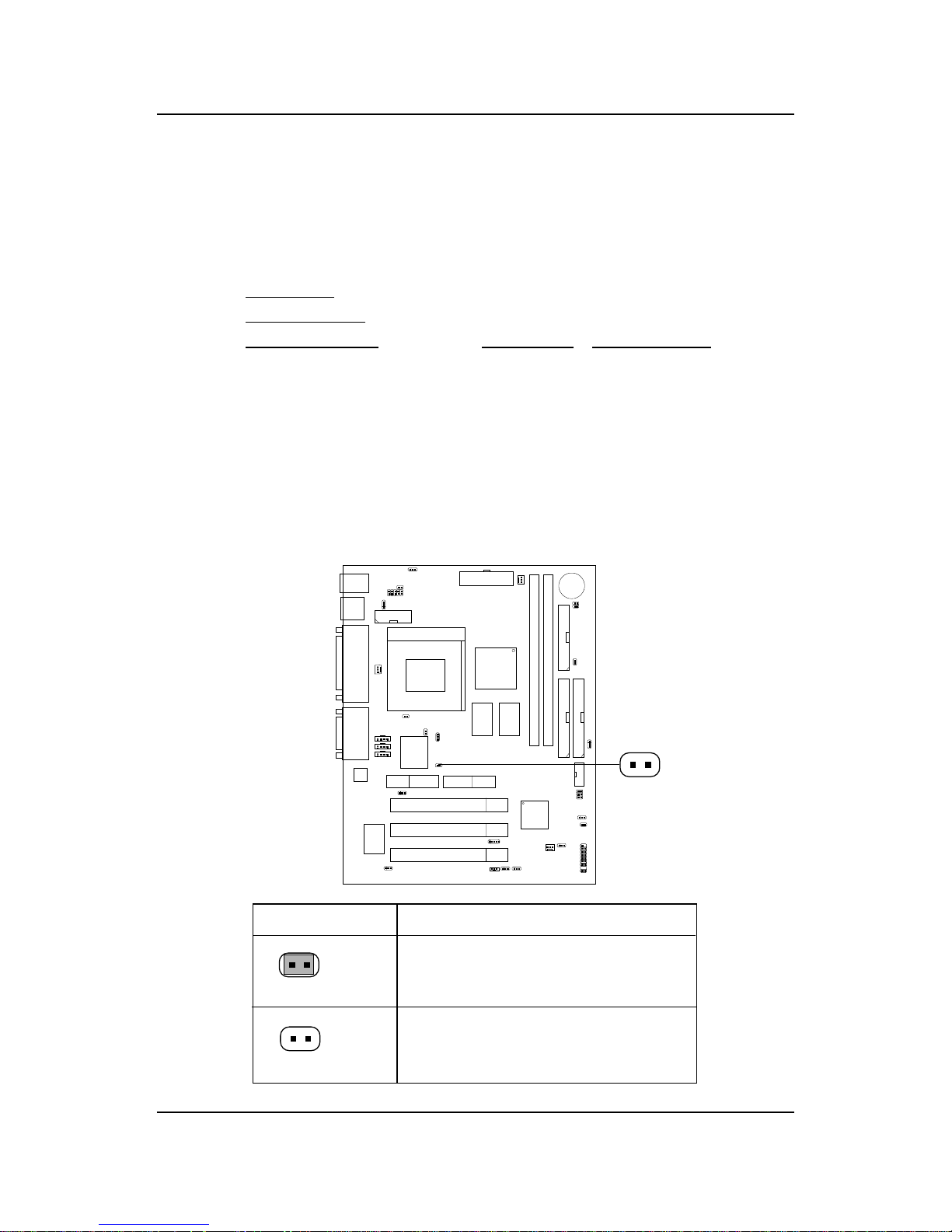
The mainboard CPU Bus Frequency can be set through BIOS setup
If CPU Clock = 66MHz
Core/Bus ratio = 3 . 5
then CPU core speed = Host Clock x Core/Bus ratio
= 66MHz x 3.5
= 233MHz
2.1-2 CPU Core Speed Derivation Procedure
J25
J25 Function
Short
Open
Automatically detect CPU
Bus Frequency
Allows CPU overclocking.
Set 66MHz to 150Mhz
2.1-3 Overclocking Jumper: J25
Overclocking is operating a CPU/Processor beyond its specified
frequency . J25 jumper is used for overclocking.
Page 62
CHAPTER 2 HARDWARE INSTALLATION
2-3
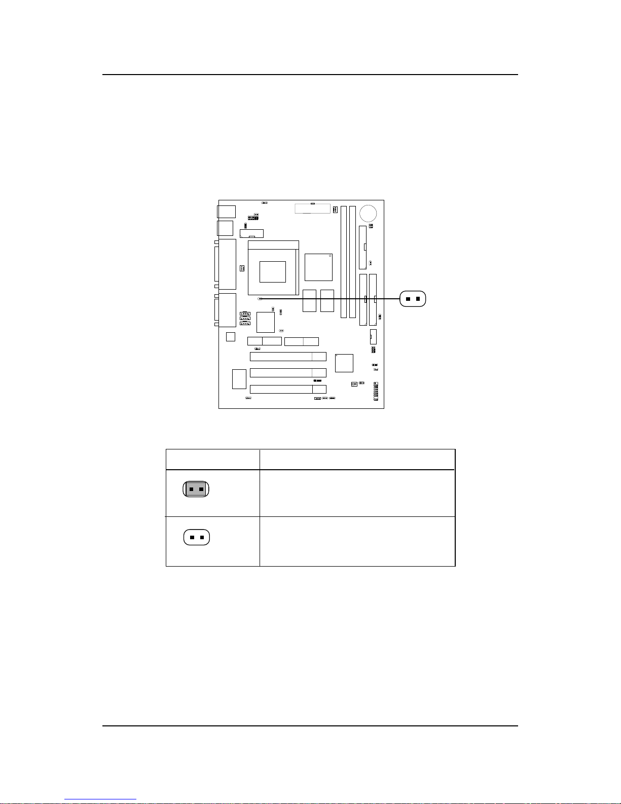
2.1-4 133Mhz for Cyrix processor: J23
This jumper is reserved for Cyrix processor that run at 133MHz.
J23 Function
Short
Open
Cyrix 133MHz processor
Default setting (100Mhz)
J23
Page 63
CHAPTER 2 HARDWARE INSTALLATION
2-4
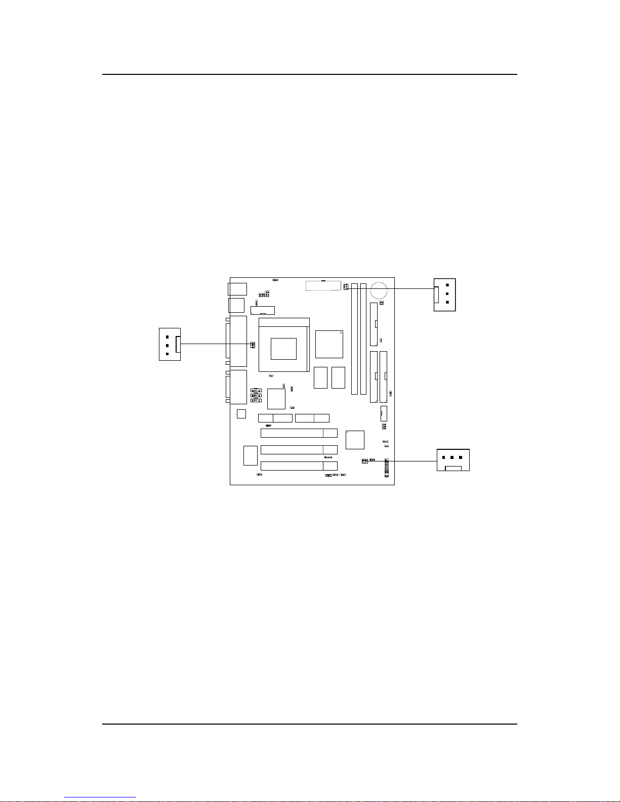
2.1-5 Fan Power Connectors: CPUFAN, PSFAN1, & SYSFAN
These connector support system cooling fan with + 12V. It supports three
pin head connector. When connecting the wire to the connector, always
take note that the red wire is the positive and should be connected to the
+12V, the black wire is Ground and should be connected to GND. If your
mainboard has System Hardware Monitor chipset on-board, you must use a
specially designed fan with speed sensor to take advantage of this function.
For fans with fan speed sensor, every rotation of the fan will send out 2
pulses. System Hardware Monitor will count and report the fan rotation
speed.
Note: 1. Always consult vendor for proper CPU cooling fan.
2. CPU F AN supports the FAN control. Y ou can install PC Alert
utility . This will automatically control the CPU F AN Speed according
to the actual CPU temperature.
CPUFAN
CPUF AN: Processor Fan
PSF AN1: Power Supply Fan (optional)
SYSF AN: System Fan (optional)
+12V
SENSOR
GND
PSFAN1
(optional)
+12V
GND
SENSOR
SYSFAN
(optional)
+12V
SENSOR
GND
Page 64
CHAPTER 2 HARDWARE INSTALLATION
2-5
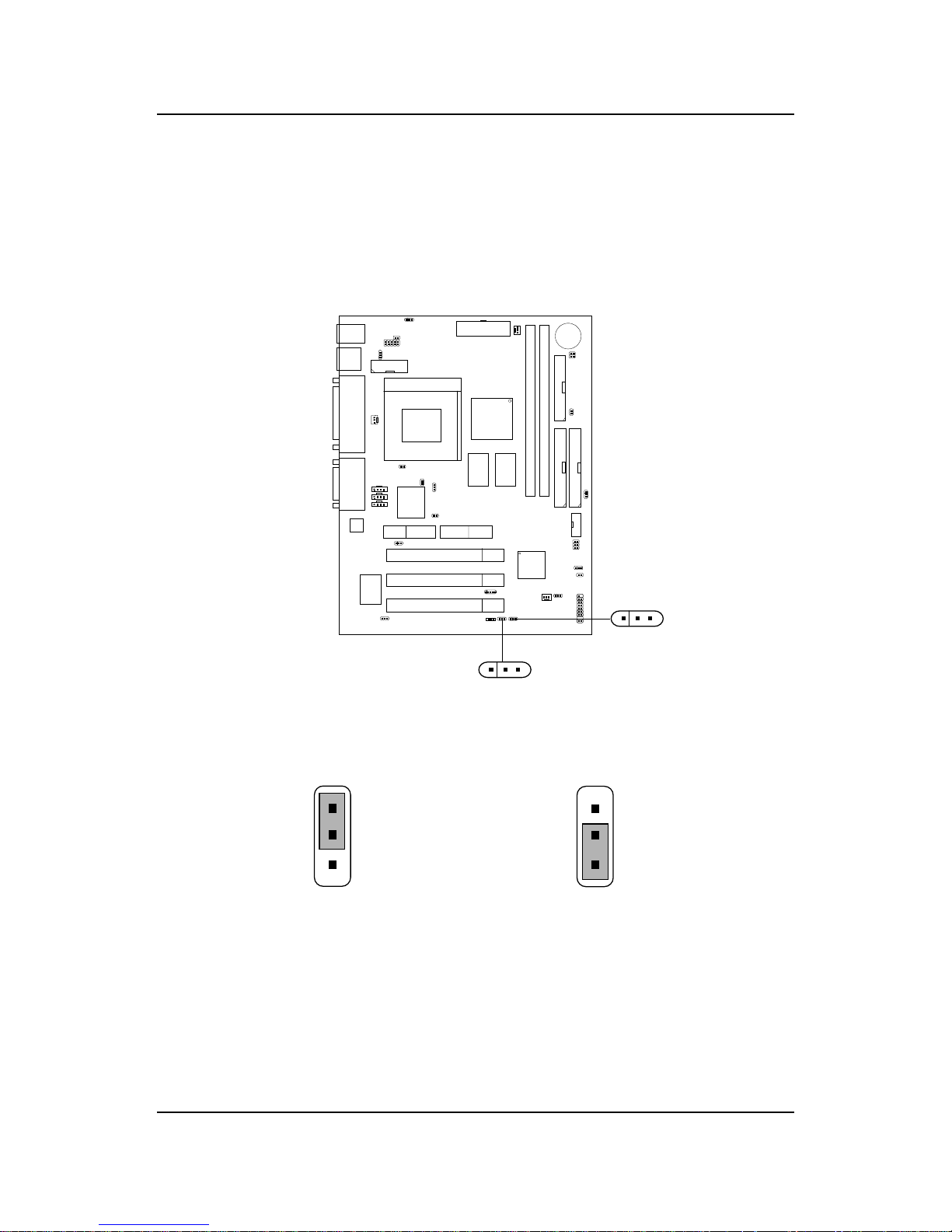
2.2 Clear CMOS Jumper: JBAT1/J26
A battery must be used to retain the mainboard configuration in CMOS
RAM. Short 1-2 pins of JBAT1/J26 to store the CMOS data.
Keep Data
Clear Data
1
1
3
3
Note: You can clear CMOS by shorting 2-3 pin, while the system is off.
Then, return to 1-2 pin position. A void clearing the CMOS while
the system is on, it will damage the mainboard. Always unplug
the power cord from the wall socket.
2
2
J26
1
3
JBAT1
1
3
Page 65
CHAPTER 2 HARDWARE INSTALLATION
2-6
2.3 Memory Installation
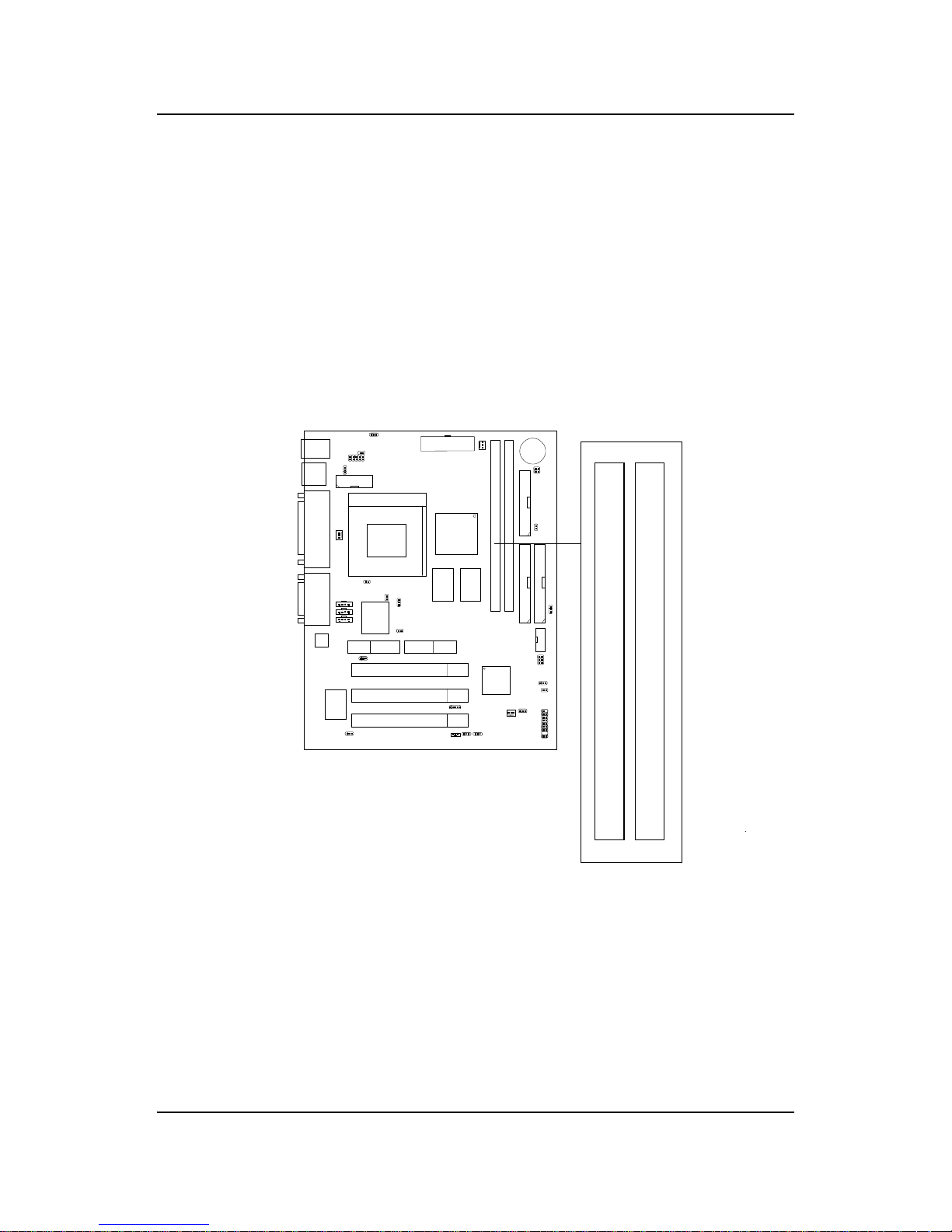
2.3-1 Memory Bank Configuration
The mainboard supports a maximum memory size of 256MB(64-bit technology) or 512MB(128-bit technology for SDRAM: It provides two 168-pin
unbuffered DIMMs (Double In-Line Memory Module) sockets. It supports
8 MB to 128 Mbytes DIMM memory module.
DIMM1(Bank0 + Bank1)
DIMM2(Bank2+ Bank3)
Page 66
CHAPTER 2 HARDWARE INSTALLATION
2-7
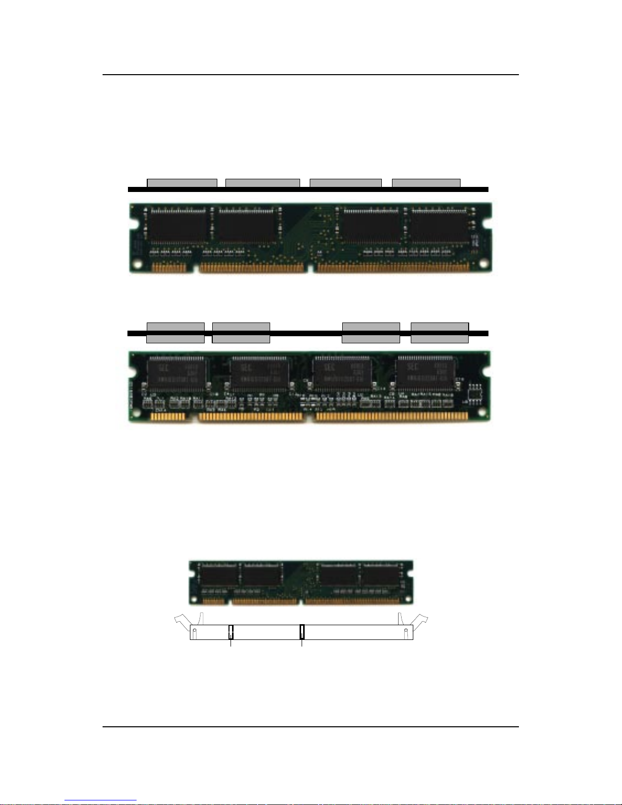
A. How to install a DIMM Module
1. The DIMM slot has 2 Notch Keys “VOLT and DRAM”, so the
DIMM memory module can only fit in one direction.
2. Insert the DIMM memory module vertically into the DIMM slot.
Then push it in.
3. The plastic clip at the side of the DIMM slot will automatically
close.
Single Sided DIMM
Double Sided DIMM
VOLTDRAM
2.3-2 Memory Installation Procedures
Page 67

CHAPTER 2 HARDWARE INSTALLATION
2-8
1 . Supports only SDRAM DIMM.
2 . To operate properly, at least one 168-pin DIMM module must be in-
stalled.
3. This mainboard supports T able Free memory , so memory can be installed
on DIMM1 or DIMM 2 in any order .
4. Supports 3.3 volt DIMM.
5. The DRAM addressing and the size supported by the mainboard is
shown below:
2.3-3 Memory Population Rules
T able 2.3-1 SDRAM Memory Addressing
16 M 1Mx16 ASYM 11 8 8 M B x 4 16MBx8
2Mx8 ASYM 1 1 9 16MBx8 32MBx16
64 M 2Mx32 ASYM 11 9 32MBx2 64MBx4
2Mx32 ASYM 12 8 16MBx2 32MBx4
4Mx16 ASYM 1 1 10 32MB 64MB
4Mx16 ASYM 13 8 32MB 64MB
8Mx8 ASYM 13 9 64MB 128MB
64 M 2Mx32 ASYM 11 8 16MB 32MB
4Mx16 ASYM 12 8 --- ---
8Mx8 ASYM 12 9 --- ---
DRAM
T ech.
DRAM
Density &
Width
DRAM
Addressing
Address Size
MB/DIMM
Row
Column
Single
Side(S)
Double
Side(D)
no.
pcs.
no.
pcs.
Page 68
CHAPTER 2 HARDWARE INSTALLATION
2-9
2.3-4 DIMM Source Voltage Setting: J27 (optional)
This jumper is used for setting DIMM source voltage setting. If J27
pin 1-3 and pin 2-4 is shorted, voltage source comes directly from the
power supply . If J27 pin 1-3 and pin 2-4 is open, voltage source
comes from the regulator.
J27 Voltage Source
Short
Open
Power Supply
Regulator
J27
1
3
2
4
Note: This jumper may not exist on some mainboard. Always leave
the jumper on factory default setting.
Page 69
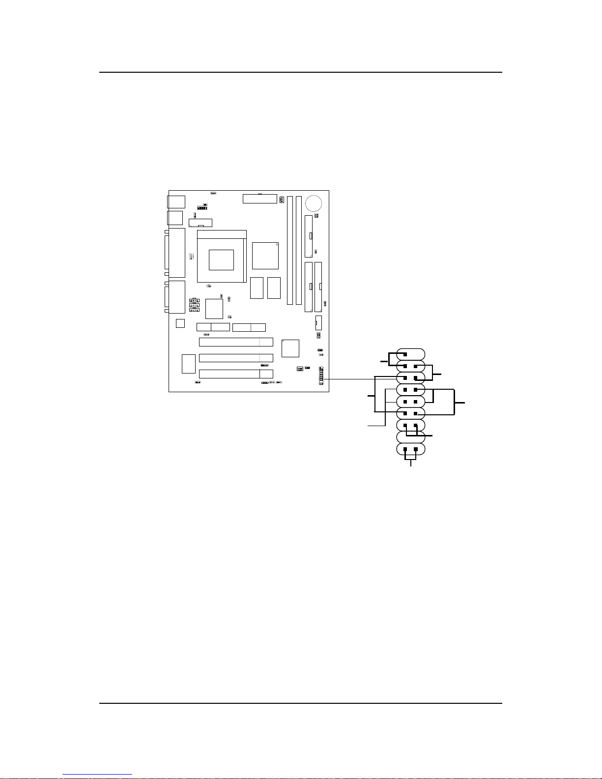
CHAPTER 2 HARDWARE INSTALLATION
2-10
2.4 Case Connector: JFP1
The Keylock, Power Switch, Reset Switch, Power LED, Speaker, and HDD
LED are all connected to the JFP1 connector block.
JFP1
Power
Switch
Power LED
+
Reset
Switch
HDD
LED
+
Speaker
Buzzer
(short
pin)
14
15
Keylock
Dual
Color
LED
Single
Color
LED
Page 70

CHAPTER 2 HARDWARE INSTALLATION
2-11
2.4-1 Power Switch
Connect to a 2-pin push button switch. This switch has the same feature
with JRMS1.
2.4-2 Reset Switch
Reset switch is used to reboot the system rather than turning the power ON/
OFF . Avoid rebooting while the HDD LED is lit. Y ou can connect the Reset
switch from the system case to this pin.
2.4-3 Power LED
The Power LED is lit while the system power is on. Connect the Power LED
from the system case to this pin. There are two types of LED that you can
use: 3-pin single color LED or 2-pin dual color LED(ACPI request).
a. 3 pin single color LED connect to pin 4, 5, & 6. This LED will lit
when the system is on.
b. 2 pin dual color LED connect to pin 5 & 6.
GREEN Color: Indicate the system is in full on mode.
ORANGE Color: Indicate the system is in suspend mode.
2.4-4 Speaker
Speaker from the system case is connected to this pin.
If on-board Buzzer is available:
Short pin 14-15: On-board Buzzer Enabled.
Open pin 14-15: On-board Buzzer Disabled.
2.4-5 HDD LED
HDD LED shows the activity of a hard disk drive. A void turning the power
off while the HDD led is lit. You can connect the HDD LED from the system
case to this pin.
2.4-6 Keylock
Keylock allows you to disable the keyboard for security purposes. You can
connect the keylock to this pin.
Page 71
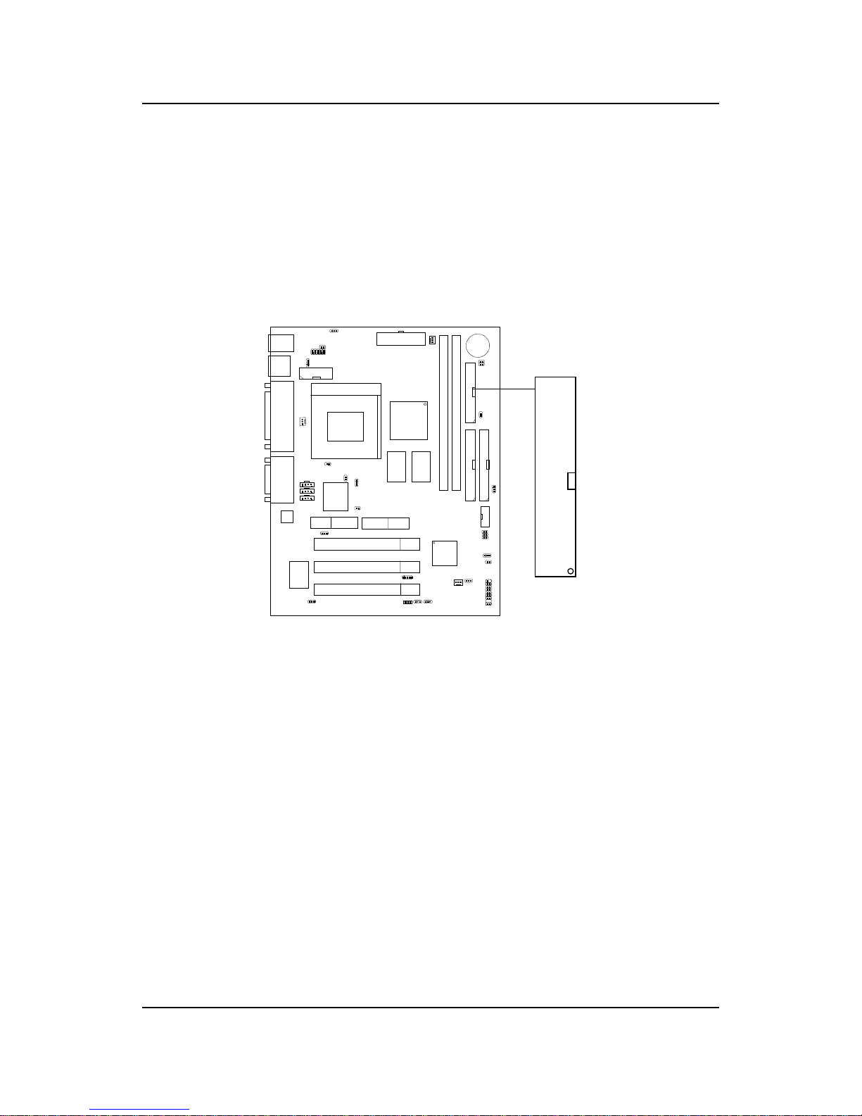
CHAPTER 2 HARDWARE INSTALLATION
2-12
2.5 Floppy Disk Connector: FDD
The mainboard also provides a standard floppy disk connector FDD that
supports 360K, 720K, 1.2M, 1.44M and 2.88M floppy disk types. This
connector supports the provided floppy drive ribbon cables.
FDD
1
Page 72
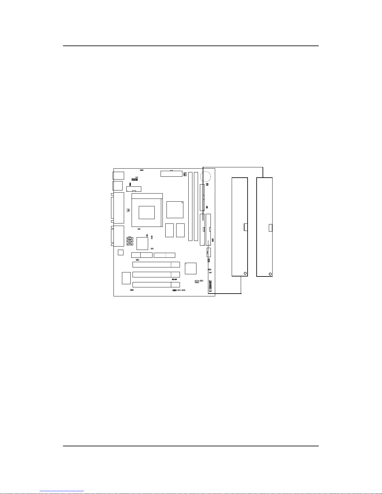
CHAPTER 2 HARDWARE INSTALLATION
2-13
2.6 Hard Disk Connectors: IDE1 & IDE2
The mainboard has a 32-bit Enhanced PCI IDE and Ultra DMA/66 (ICH)/
Ultra DMA/33(ICH0) Controller that provides PIO mode 0~4, Bus Master,
and Ultra DMA/33 function. It has two HDD connectors IDE1 (primary) and
IDE2 (secondary). You can connect up to four hard disk drives, CD-ROM,
120MB Floppy (reserved for future BIOS) and other devices to IDE1 and
IDE2. These connectors support the provided IDE hard disk cable.
IDE1(Primary IDE Connector)
The first hard drive should always be connected to IDE1. IDE1 can
connect a Master and a Slave drive. You must configure second hard
drive to Slave mode by setting the jumper accordingly .
IDE2(Secondary IDE Connector)
IDE2 can also connect a Master and a Slave drive.
Primary IDE Connector
Secondary IDE Connector
1
1
Page 73
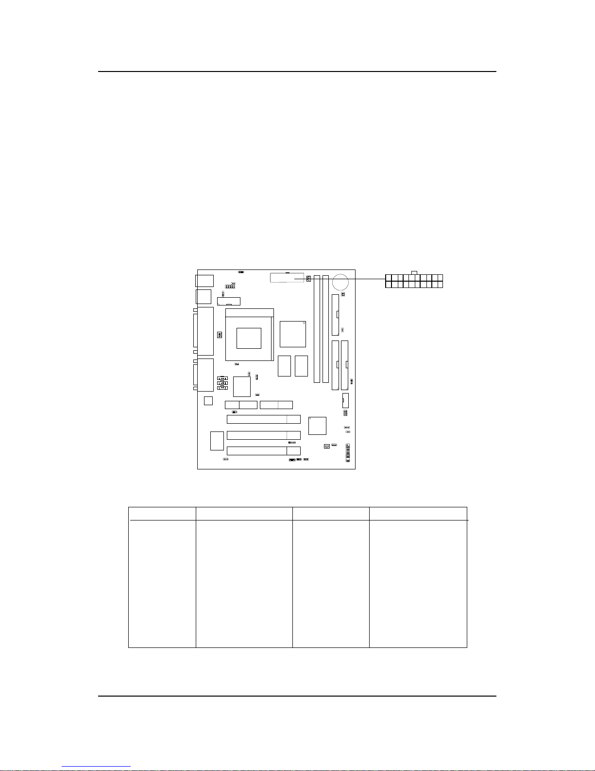
CHAPTER 2 HARDWARE INSTALLATION
2-14
2.7 Power Supply
2.7-1 ATX 20-pin Power Connector: JWR1
This connector supports the power button on-board. Using the ATX power
supply , functions such as Modem Ring Wake-Up and Soft Power Off are
supported by this mainboard. This power connector supports instant power
on function which means that system will boot up instantly when the power
connector is inserted on the board.
PIN SIGNAL
11 3.3V
12 -12V
13 GND
14 PS_ON
15 GND
16 GND
17 GND
18 -5V
19 5V
20 5V
PIN SIGNAL
1 3.3V
2 3.3V
3 GND
45V
5 GND
65V
7 GND
8 PW_OK
9 5V_SB
10 12V
PIN DEFINITION
Warning: Since the mainboard has the instant power on function, make
sure that all components are installed properly before inserting the power
connector to ensure that no damage will be done.
AT X
Power Connector
11
20
10 1
Page 74
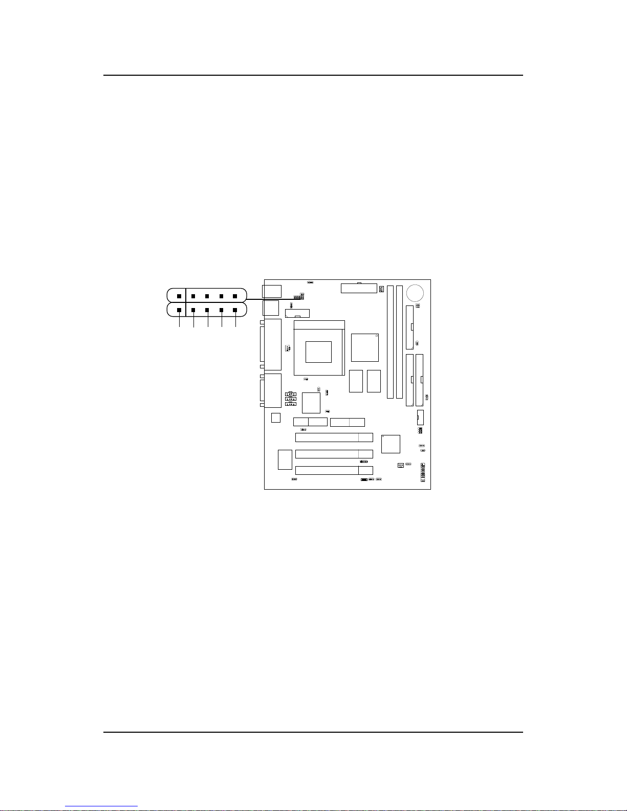
CHAPTER 2 HARDWARE INSTALLATION
2-15
2.8 IrDA Infrared Module Connector: J9
The mainboard provides one infrared (J9) connector for IR modules. This
connector is for optional wireless transmitting and receiving infrared module.
You must configure the setting through the BIOS setup to use the IR
function.
VCC
NC IRRX GND IRTX
1
J9
Page 75
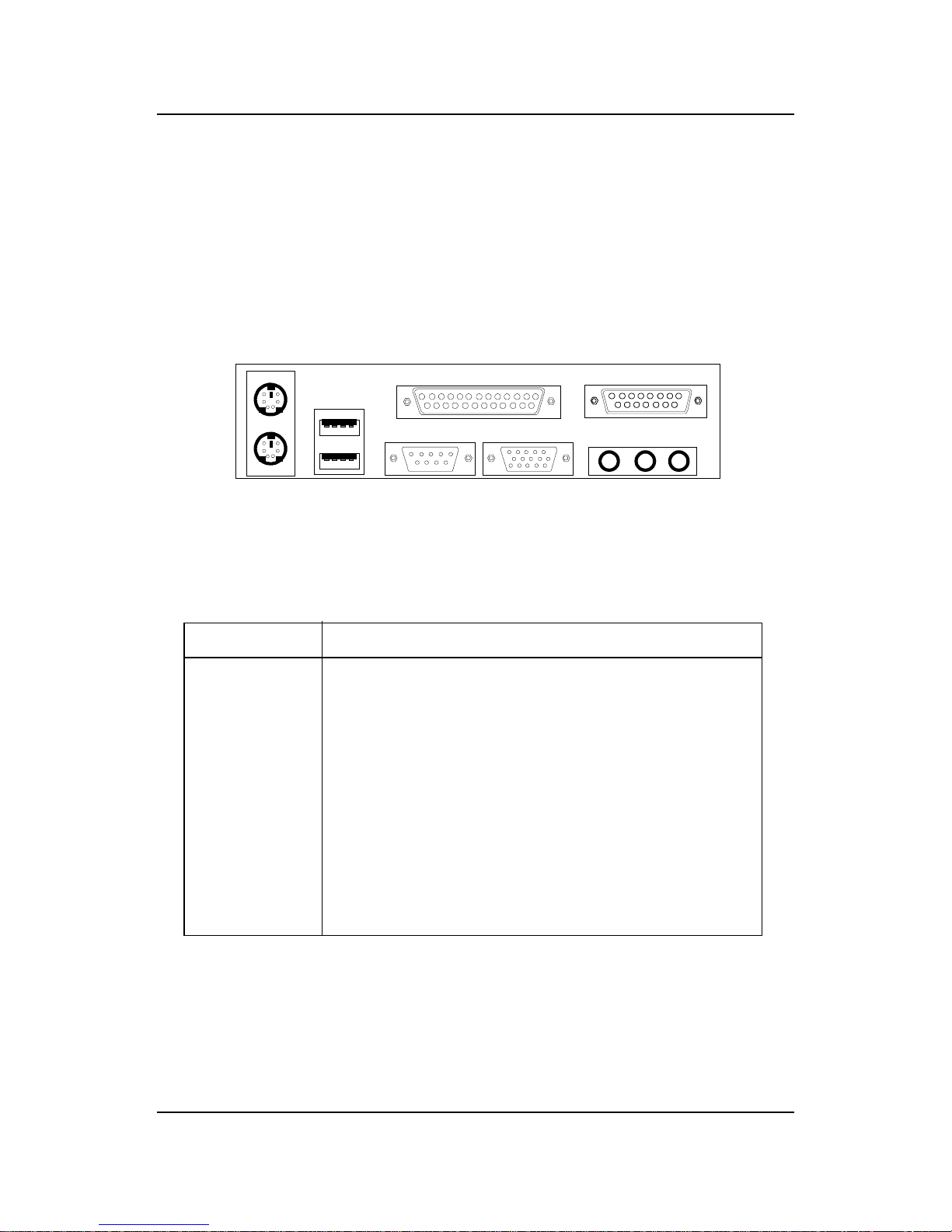
CHAPTER 2 HARDWARE INSTALLATION
2-16
2.9 Serial Port Connectors: COM A and COM B
The mainboard has a 9-pin male DIN connector for serial port COM A. This
port is a 16550A high speed communication port that send/receive 16 bytes
FIFOs. You can attach a mouse or a modem cable directly into this connector .
PIN SIGNAL
1 DCD(Data Carry Detect)
2 SIN(Serial In or Receive Data)
3 SOUT(Serial Out or Transmit Data)
4 DTR(Data T erminal Ready)
5 GND
6 DSR(Data Set Ready)
7 RTS(Request To Send)
8 CTS(Clear To Send)
9 RI(Ring Indicate)
PIN DEFINITION
1 2 3 4 5
6 7 8 9
COM 1
Serial Port (9-pin Male)
Note: There’ s another serial port connector (COM B), which is
located on the mainboard. Connect a serial port 9-pin male
port into this connector.
Page 76
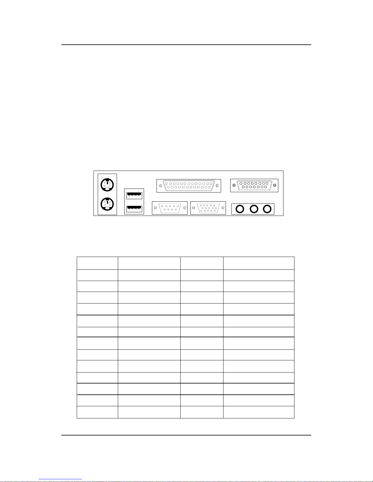
CHAPTER 2 HARDWARE INSTALLATION
2-17
2.10 Parallel Port Connector: LPT1
The mainboard provides a 25 pin female centronic connector for LPT . A
parallel port is a standard printer port that also supports Enhanced Parallel
Port(EPP) and Extended capabilities Parallel Port(ECP). See connector and
pin definition below:
PIN SIGNAL PIN SIGNAL
1 STROBE 1 4 AUTO FEED#
2 DAT A0 15 ERR#
3 DATA1 16 INIT#
4 DAT A2 17 SLIN#
5 DATA3 18 GND
6 DATA4 19 GND
7 DATA5 20 GND
8 DATA6 21 GND
9 DATA7 22 GND
10 ACK# 23 GN D
11 BUSY 24 G ND
12 PE 25 GND
13 SELECT
PIN DEFINITION
LPT 1
13
Parallel Port (25-pin Female)
1
25
14
Page 77
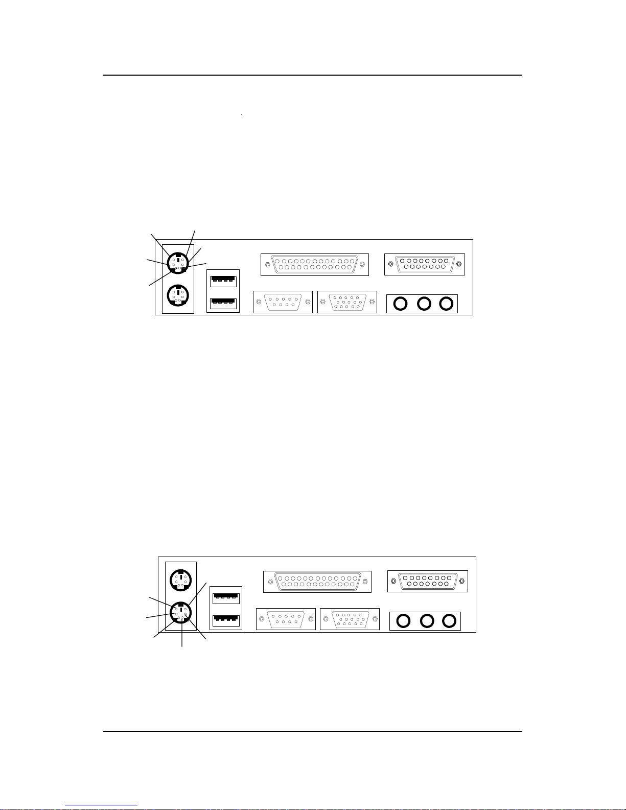
CHAPTER 2 HARDWARE INSTALLATION
2-18
2.11 Mouse Connector: JKBMS1
The mainboard provides a standard PS/2® mouse mini DIN connector for
attaching a PS/2® mouse. You can plug a PS/2® mouse directly into this
connector. The connector location and pin definition are shown below:
2.12 Keyboard Connector: JKBMS1
The mainboard provides a standard PS/2® keyboard mini DIN connector for
attaching a keyboard. You can plug a keyboard cable directly to this
connector .
PS/2 Mouse (6-pin Female)
PS/2 Keyboard (6-pin Female)
Pin1
Mouse DATA
Pin6
NC
Pin2
NC
Pin4
VCC
Pin3
GND
Pin5
Mouse Clock
Pin1
KBD DATA
Pin6
NC
Pin2
NC
Pin3
GND
Pin5
KBD Clock
Pin4
VCC
Page 78
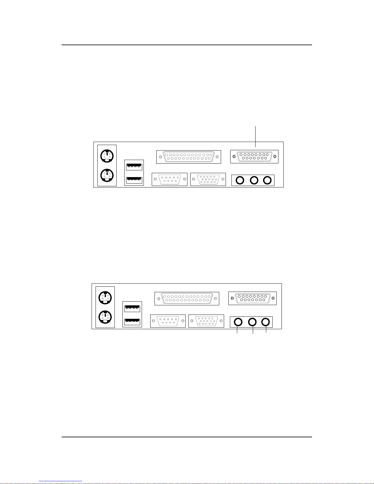
CHAPTER 2 HARDWARE INSTALLATION
2-19
2.14 Audio Port Connectors
Line Out is a connector for Speakers or Headphones. Line In is used for
external CD player, T ape layer , or other audio devices. Mic is a connector for
the microphones.
Line Out
Line In
Mic
1/8” Stereo Audio Connectors
2.13 Joystick/Midi Connectors
You can connect joystick or game pad to this connector.
Joystick/MIDI
Page 79
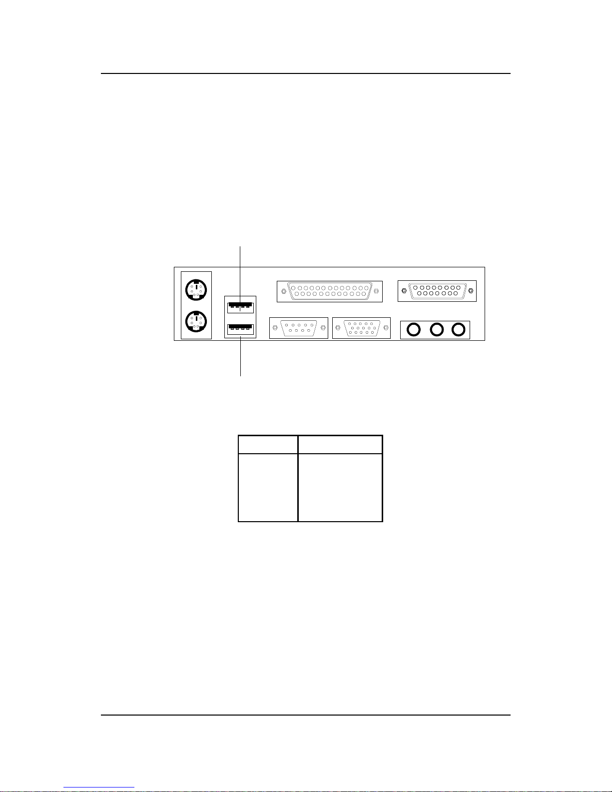
CHAPTER 2 HARDWARE INSTALLATION
2-20
2.15 USB Connectors
The mainboard provides a UHCI(Universal Host Controller Interface)
Universal Serial Bus root for attaching USB devices like: keyboard, mouse
and other USB devices. You can plug the USB device directly to this
connector .
USB Port 1
USB Port 2
PIN SIGNAL
1 VCC
2 -Data
3 +Data
4 GND
1 2 3 4
Page 80
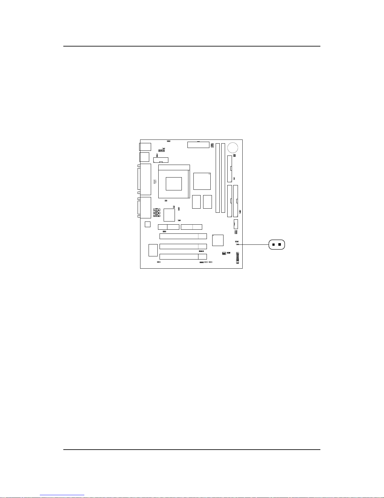
CHAPTER 2 HARDWARE INSTALLATION
2-21
2.16 Power Saving Switch Connector: JGS1
Attach a power saving switch to JGS1. When the switch is pressed, the
system immediately goes into suspend mode. Press any key and the system
wakes up.
JGS1
Page 81
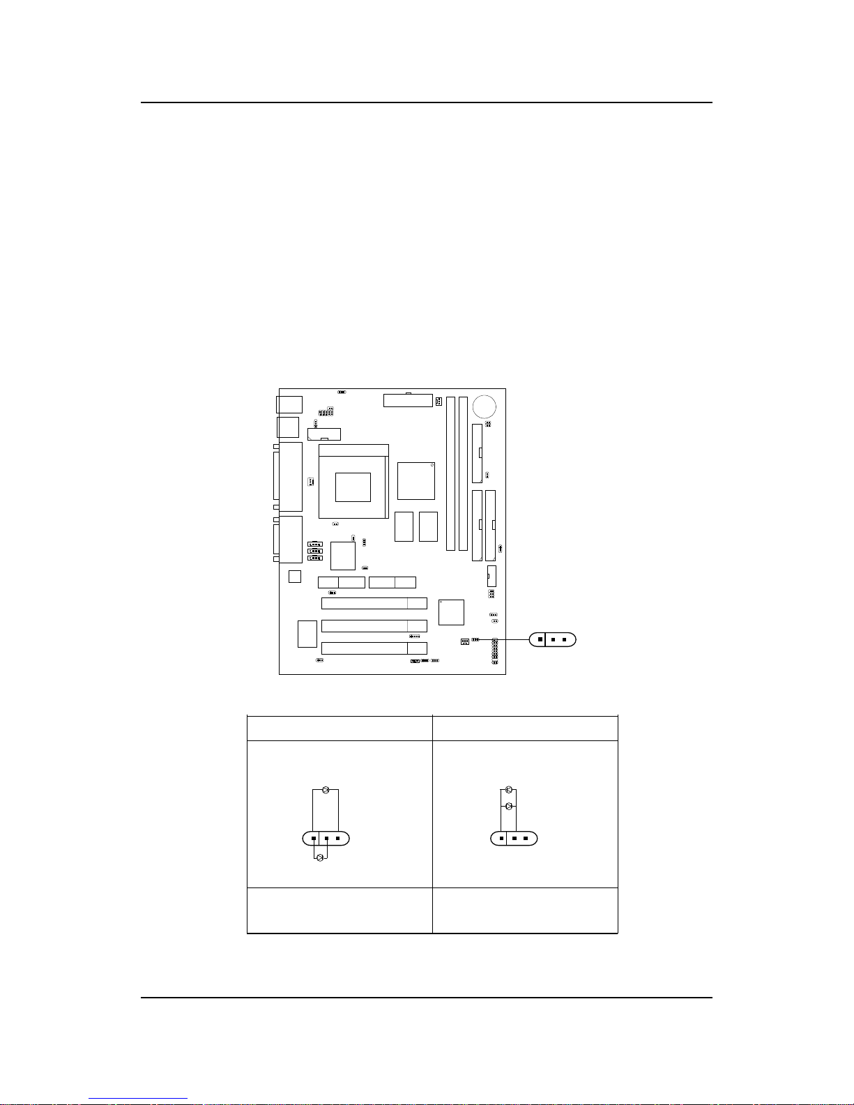
CHAPTER 2 HARDWARE INSTALLATION
2-22
2.17 Power Saving LED Connector: JGL1
JGL1 can be connected with an LED. There are two types of LED that you
can use: 3-pin LED or 2-pin LED(ACPI request). When the 2-pin LED is
connected to JGL1, the light will turn green, when system is On. During
sleep mode, the 2-pin LED will change color from Green to Orange. For 3-pin
LED, when LED is connected to JGL1, this will light when the system is On
and blinks when it is in suspend/sleep mode. See page 3-19 (Power status
LED) for further instruction.
3-pin LED 2-pin LED
1
3
Green Color
Orange
Color
1
3
Green Color
Orange
Color
1-2 Single Color 1-2 Dual Color
1-3 Blink
JGL1
+
1
3
Page 82
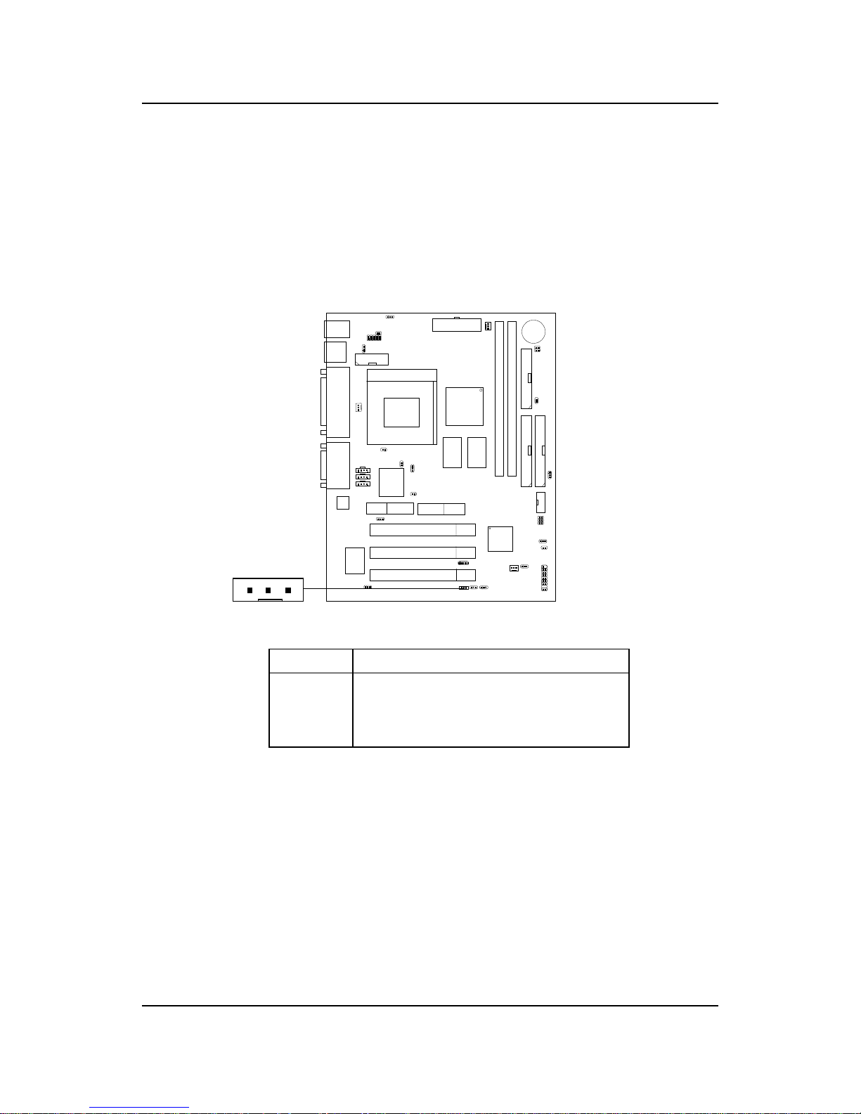
CHAPTER 2 HARDWARE INSTALLATION
2-23
2.18 Wake-Up on LAN Connector: JWOL1
The JWOL1 connector is for use with LAN add-on cards that supports
Wake Up on LAN function. To use this function, you need to set the
“W ake-Up on LAN” to enable at the BIOS Power Management Setup.
PIN SIGNAL
1 5VSB
2 GND
3 MP_WAKEUP
Note: LAN wake-up signal is active “high”.
Note: To be able to use this function, you need a power supply that
provide enough power for this feature. (Power supply with 750ma
5V Stand-by)
JWOL1
13
Page 83
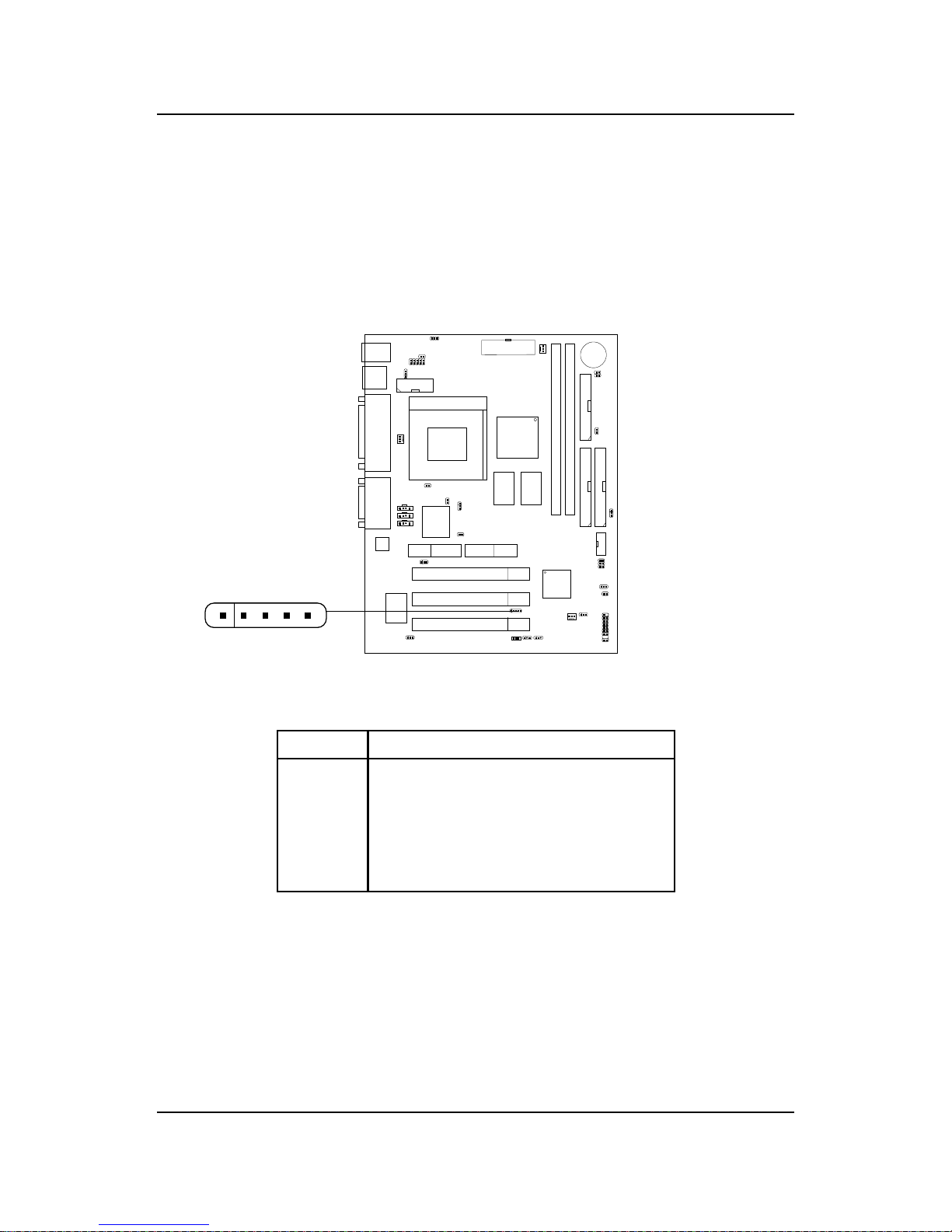
CHAPTER 2 HARDWARE INSTALLATION
2-24
2.19 Modem Wake Up Connector: JMDM1
The JMDM1 connector is for used with Modem add-on card that supports
the Modem Wake Up function.
Note: Modem wake-up signal is active “low”.
PIN SIGNAL
1NC
2 GND
3 MDM_WAKEUP
4NC
5 5VSB
Note: To be able to use this function, you need a power supply that
provide enough power for this feature. (Power supply with 750ma
5V Stand-by)
JMDM1
15
Page 84
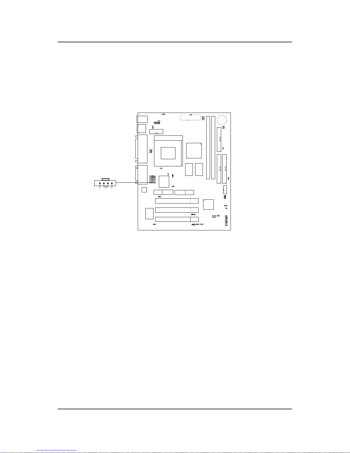
CHAPTER 2 HARDWARE INSTALLATION
2-25
2.20 Modem-In: J21
The connector is for Modem with internal voice connector .
Mono_Out is connected to the Modem Speaker Out connector.
Phone_In is connected to the Modem Microphone In connector.
Modem_In
Mono_Out
GND
Phone_In
Page 85
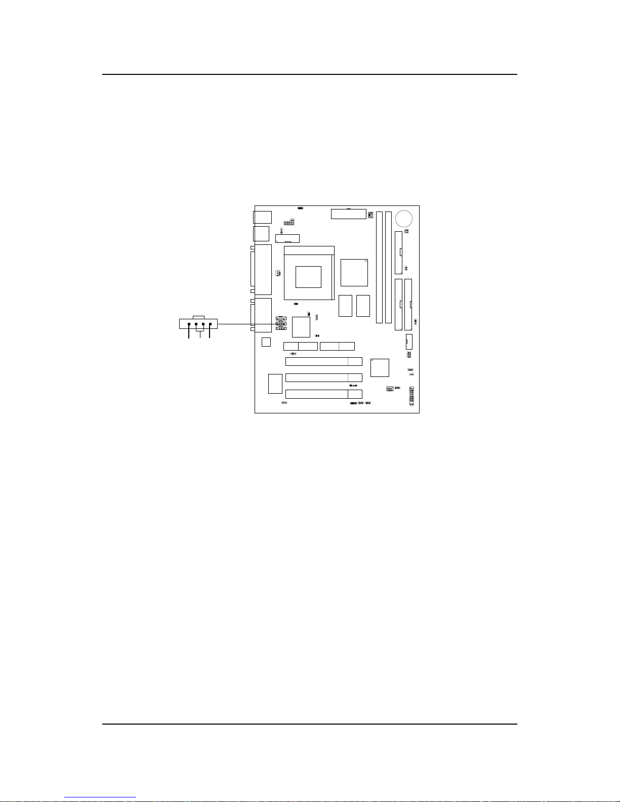
CHAPTER 2 HARDWARE INSTALLATION
2-26
2.21 AUX Line In Connector: J20
This connector is used for DVD Add on Card with Line In connector.
AUX_IN
R GND L
Page 86
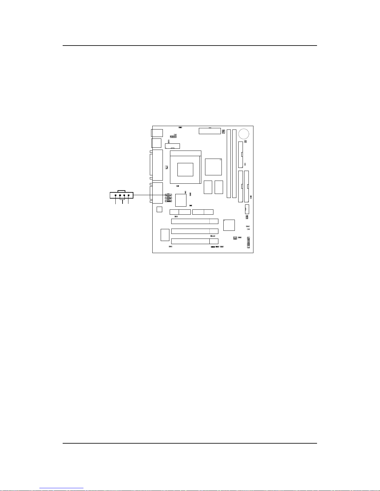
CHAPTER 2 HARDWARE INSTALLATION
2-27
2.22 CD-In Connector: J19
This connector is for CD-ROM audio connector .
CD_In
LGNDR
Page 87
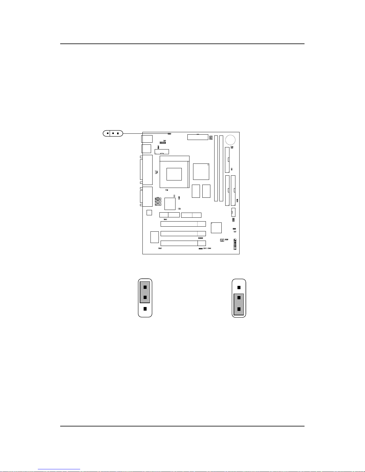
CHAPTER 2 HARDWARE INSTALLATION
2-28
2.23 Keyboard Power: JKBV1
The JKBV1 jumper is for setting keyboard power . This function should be
set in the BIOS for the keyboard W ake-up function.
JKBV1
1
3
5V (default)
Disable keyboard
power on function
5V Standby
Enable keyboard
power on function
1
3
1
3
Note: To be able to use this function, you need a power supply that
provide enough power for this feature. (750mA power
supply with 5V Stand-by)
Page 88
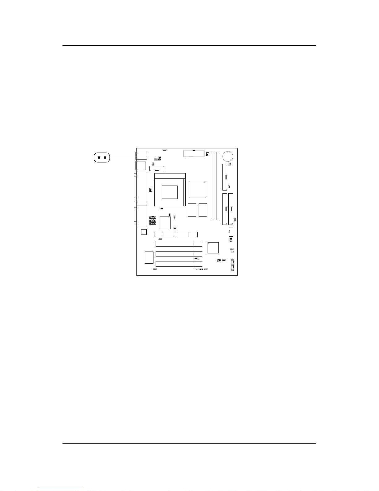
CHAPTER 2 HARDWARE INSTALLATION
2-29
2.24 Chassis Intrusion Switch Case: J10(optional)
This connector is connected to a 2-pin connector chassis switch. If the
Chassis is open, the switch will be open. The system will record this status.
To clear the warning, you must enter the BIOS settting and clear the status.
J10
Page 89
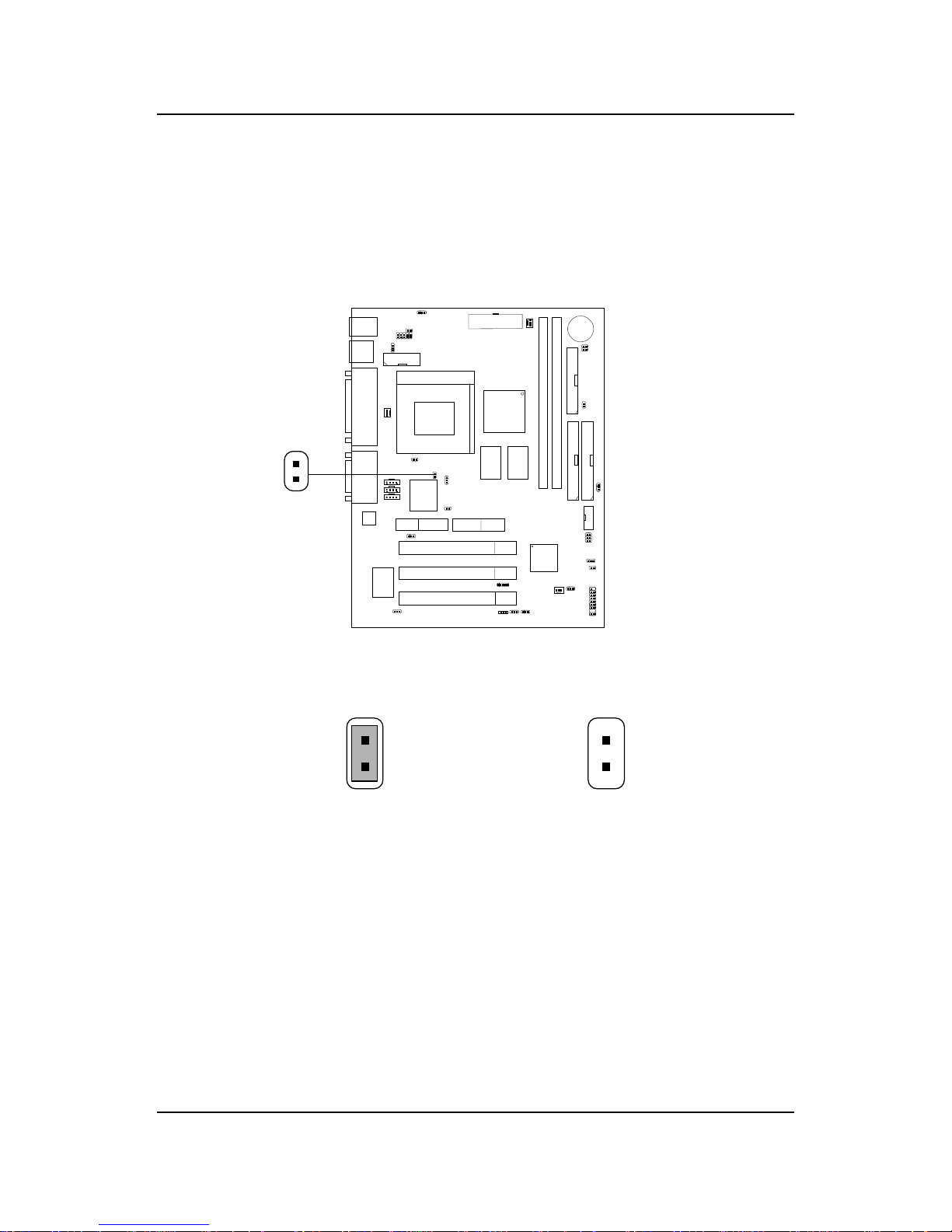
CHAPTER 2 HARDWARE INSTALLATION
2-30
2.25 BIOS Flash Jumper: JP3
This jumper is used to locked/unlocked BIOS Flash. This Jumper should be
unlock when flashing/programming the BIOS.
BIOS Flash
Unlocked
BIOS Flash
Locked
JP3
Page 90
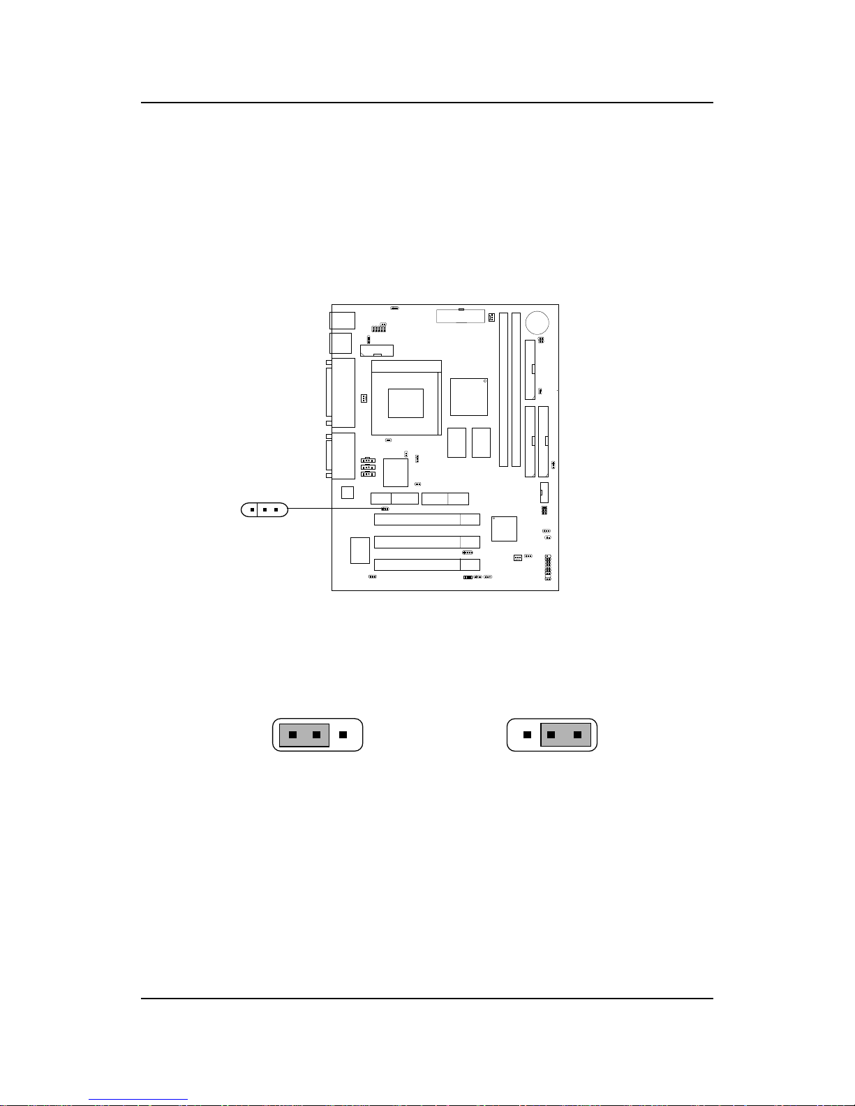
CHAPTER 2 HARDWARE INSTALLATION
2-31
2.26 Onboard Audio Enabled/Disabled
Jumper: JP4
This jumper is used to Enabled/Disabled the onboard Soft audio codec.
Enabled Disabled
1
13
3
JP4
1
3
Page 91
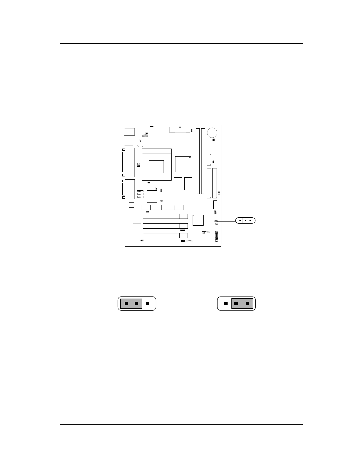
CHAPTER 2 HARDWARE INSTALLATION
2-32
2.27 Case Speaker to Audio Speaker Jumper:
J15
This jumper is used to Enabled the case speaker to be transfered to Audio
speaker.
To Audio
Speaker
Normal
1
13
3
J15
1
3
Page 92
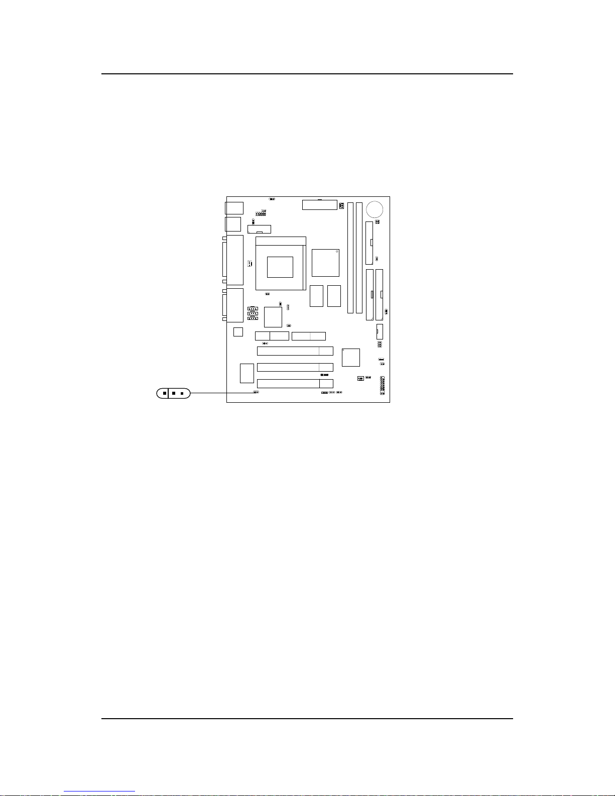
CHAPTER 2 HARDWARE INSTALLATION
2-33
2.28 SPDIF Connector: J22 (optional)
This item is for Sony & Philips Digital Interface for AC3 decoder.
1
3
VCC
SDPIF_Out
GND
J22
Page 93
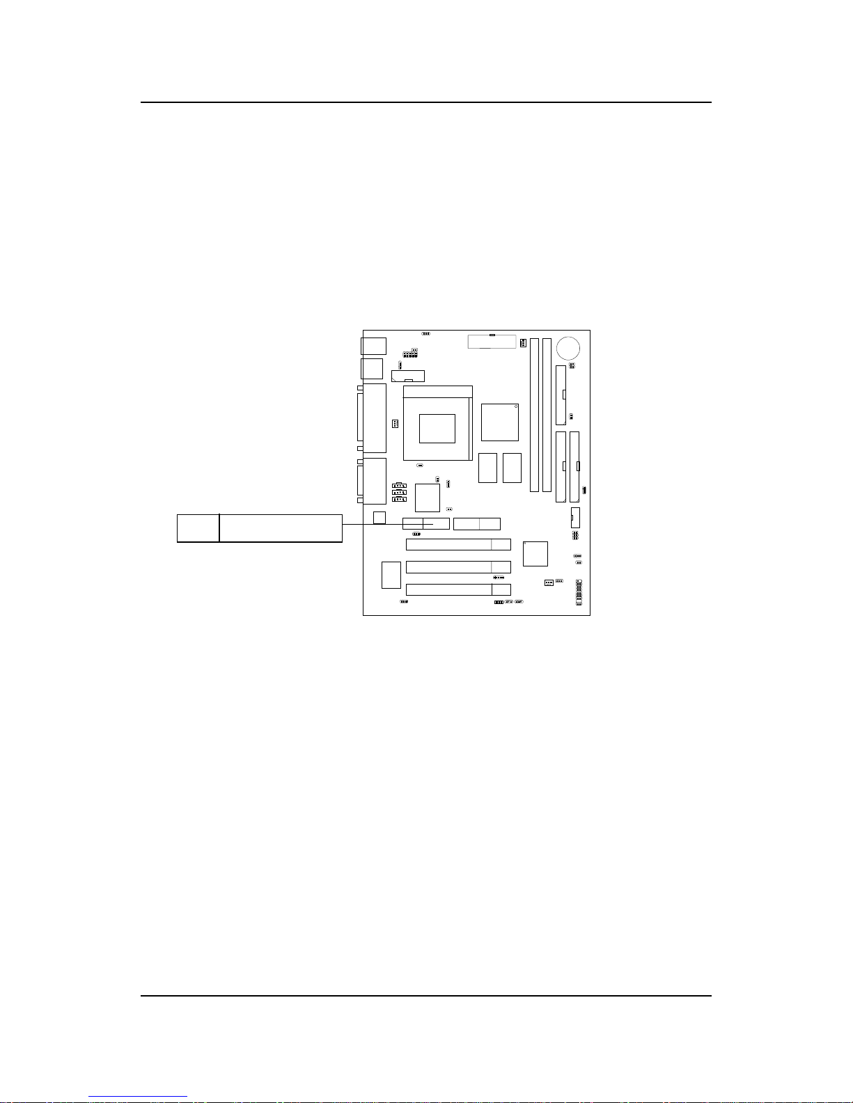
CHAPTER 2 HARDWARE INSTALLATION
2-34
2.29 AMR (Audio Modem Riser)
The Audio/Modem Riser specification is an open industry-standard
specification that defines a hardware scalable Original Equipmet
Manufacturer (OEM) mainboard riser board and interface, which supports
both audio and modem.
AMR
Page 94
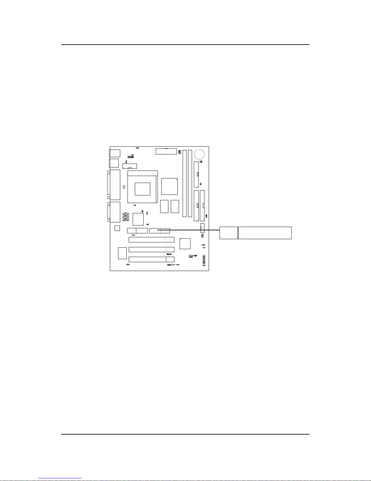
CHAPTER 2 HARDWARE INSTALLATION
2-35
2.30 PTI (PanelLink TV-Out Interface)
The Panel link/TV-Out Interface (PTI) is a MSI in-house designed which
supportd either Panel link or TV-out function. T o be able utilize both AMR
and PTI simultaneously you need to use MSI product like MS-5965 & MS5966 or MS-5964 & MS-5966.
PTI
Page 95
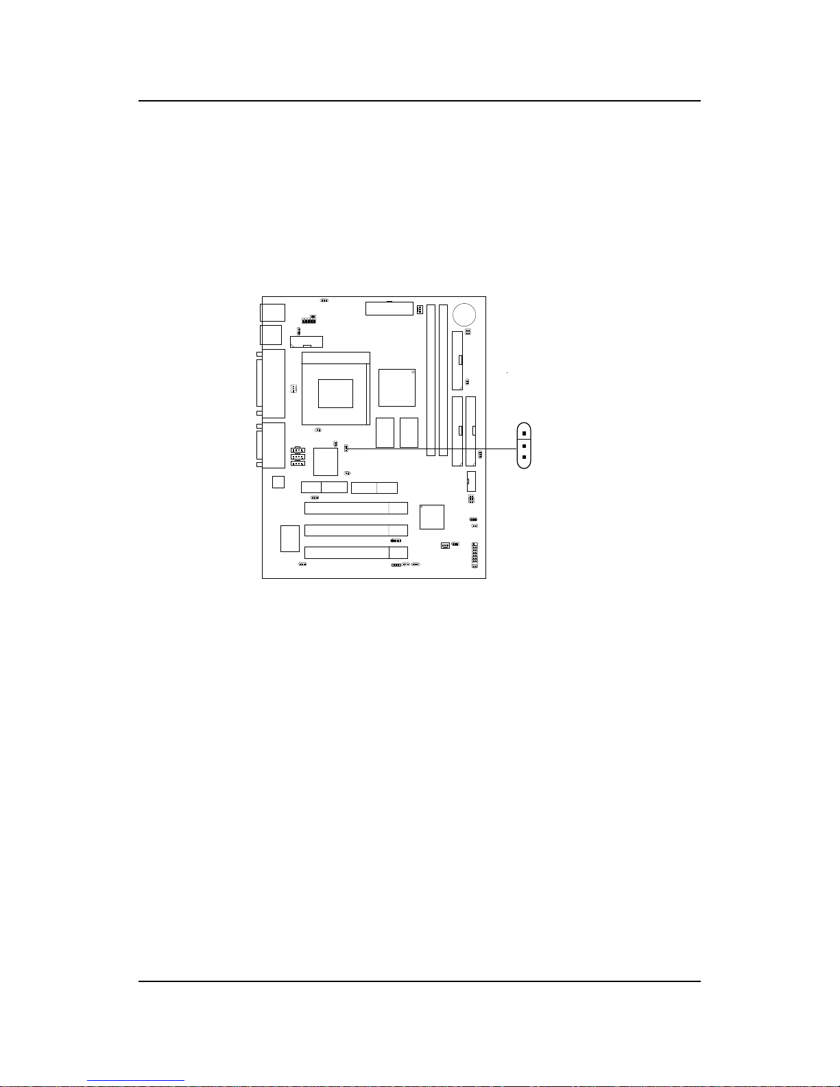
CHAPTER 2 HARDWARE INSTALLATION
2-36
2.31 STR (Suspend to RAM) Jumper: J24 (optional)
This mainboard may or may not support STR (Suspend to RAM). If J24 pin
2-3 is shorted, the system supports STR (Suspend to RAM). If J24 is open,
the system does not support STR (Suspend to RAM).
J24
1
3
NOTE: Do not try to alter or change the motherboard’ s default setting. The
default setting will depend on the motherboard manufacturer .
Page 96
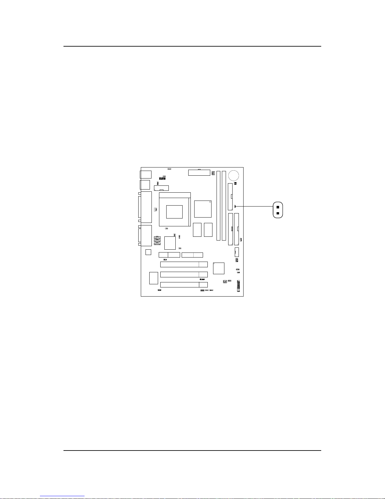
CHAPTER 2 HARDWARE INSTALLATION
2-37
2.32 STR (Suspend to RAM) Power Jumper: J28
(optional)
This jumper may depend on two conditions:
A. For motherboard which supports STR, Jumper J28 is reserved for some
power supply . If standby power is not enough (e.g. less than 750 mA), J28
should be open. The default setting is short.
B. For motherboard which do not support STR, J28 should always be open.
J28
Page 97
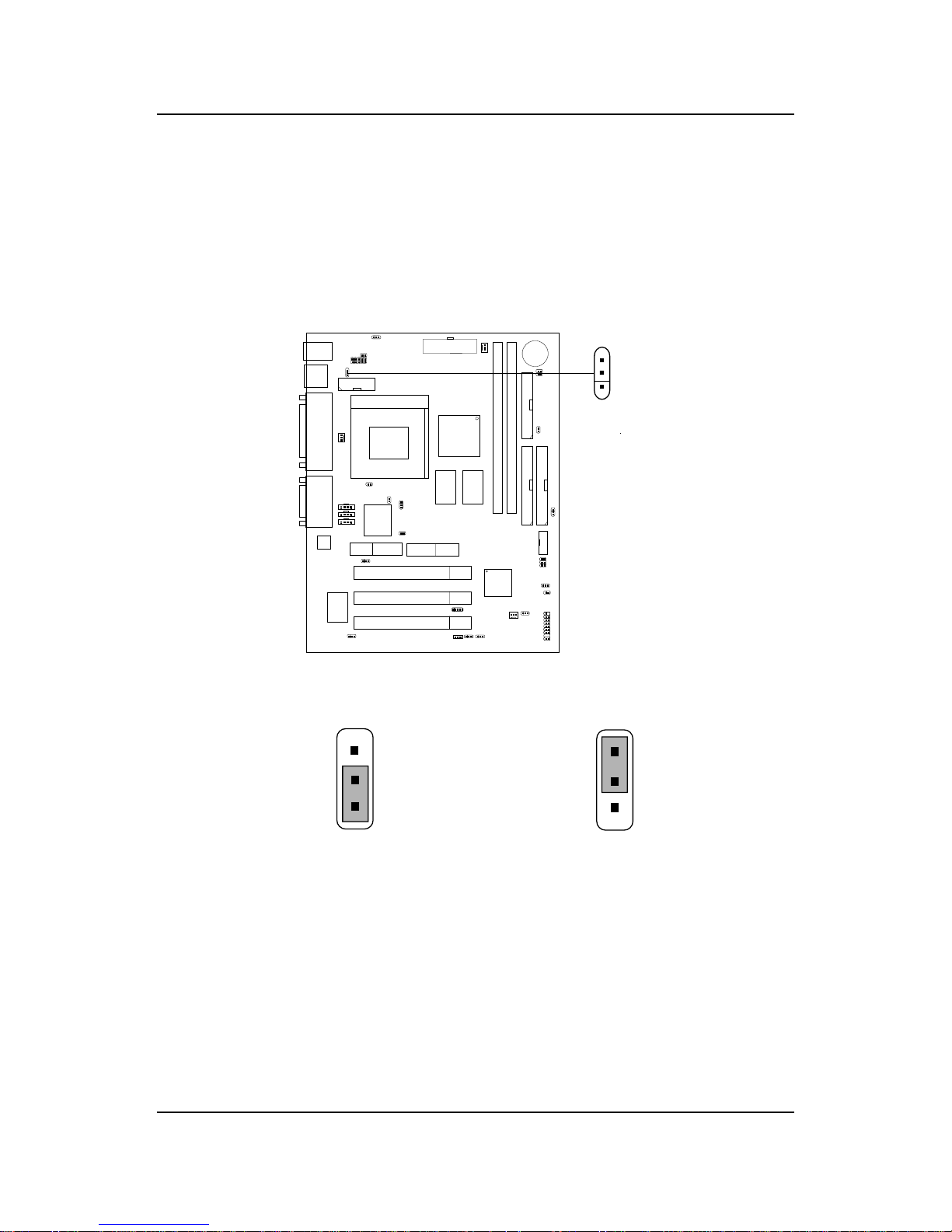
CHAPTER 2 HARDWARE INSTALLATION
2-38
2.33 USB Device Power Jumper: JUSBV1
(optional)
This jumper provides Vcc or 5V standby setting for USB Device Power.
Vcc (Default) USB Device Power
5V Standby
1
1
3
3
JUSBV1
1
3
Page 98
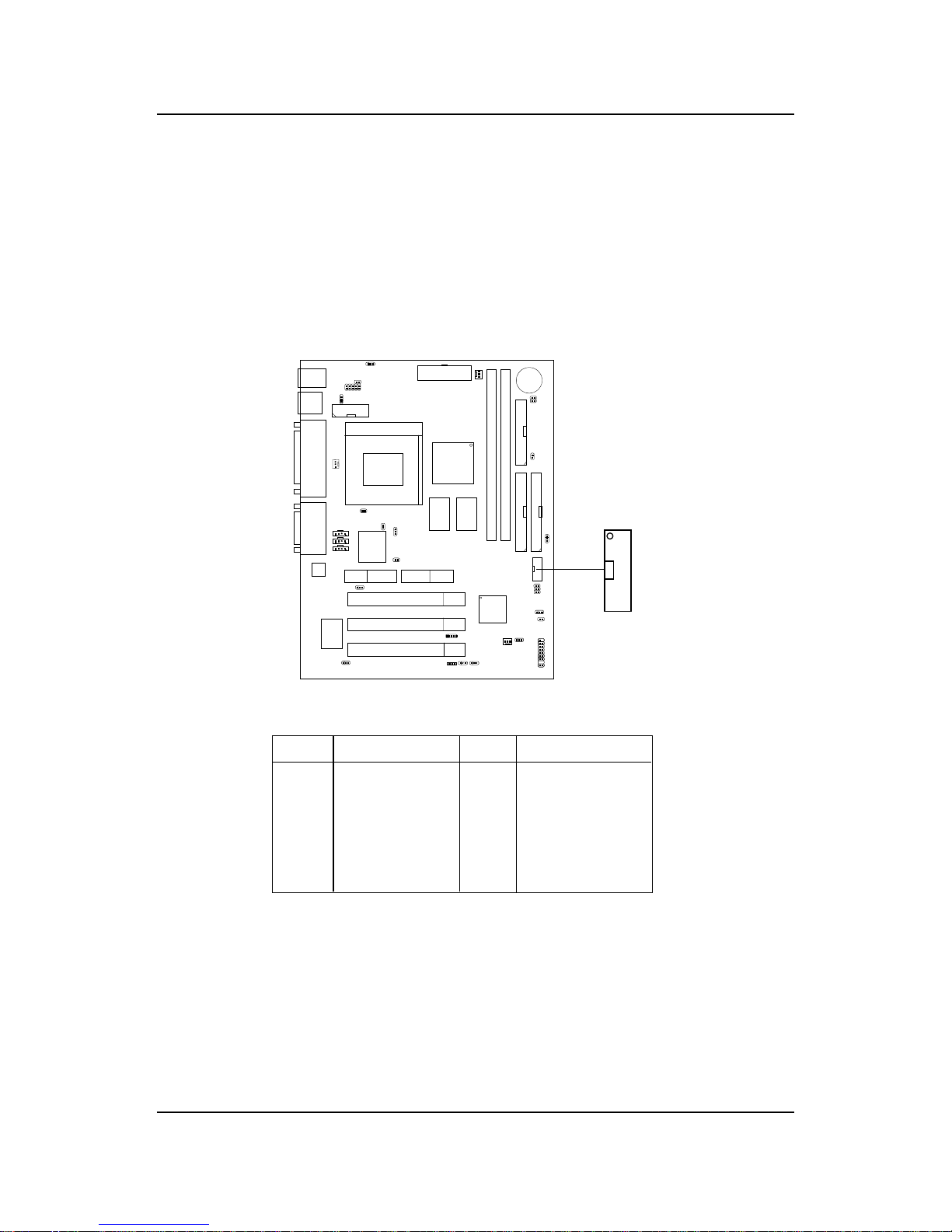
CHAPTER 2 HARDWARE INSTALLATION
2-39
2.34 USB Front Connector: USB2 (optional)
The mainboard provides a front Universal Serial Bus connector. This is an
optional USB connector for Front Panel.
USB2
1
2
9
10
Pin Description Pin Description
1 NC 6 +Data
2 VCC 7 GN D
3 G ND 8 -Data
4 NC 9 GND
5NC 10NC
Page 99
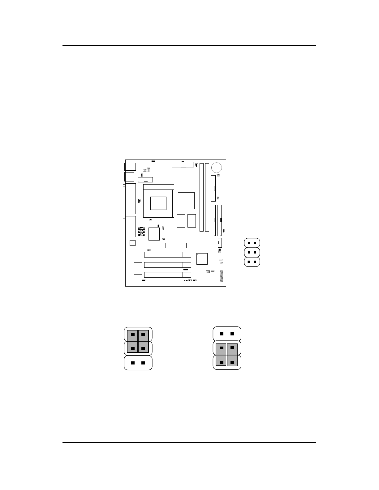
CHAPTER 2 HARDWARE INSTALLATION
2-40
2.35 USB Front Connector Enabled/Disabled
Jumper: J17 (optional)
This jumper is used to Enabled or Disabled the USB Front Connector. If the
USB Front connector is set to enabled, the top USB port at the rear I/O
panel will be disabled. If the USB Front connector is set to disabled, the
USB ports at rear I/O panel will both be operational.
Enabled
Disabled
1
3
4
6
1
3
4
6
J17
1
3
4
6
Page 100
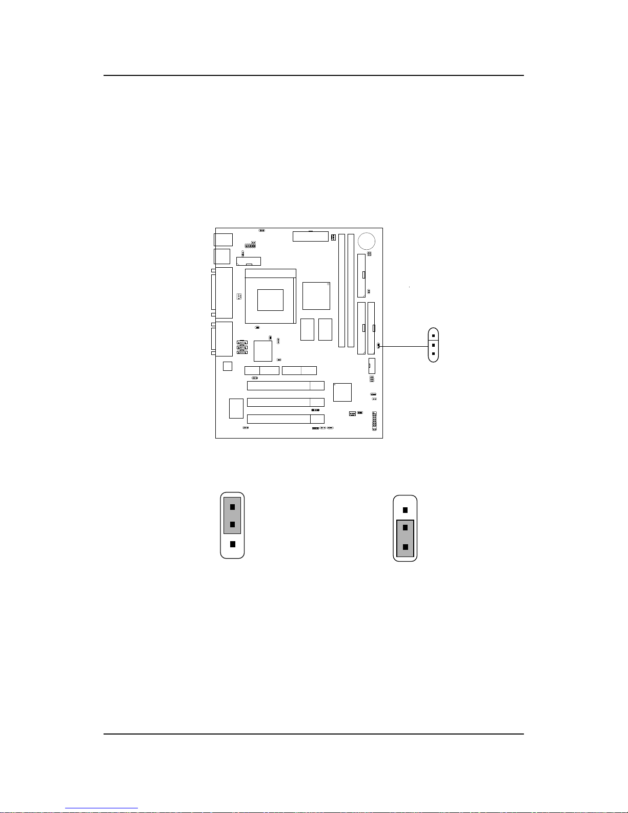
CHAPTER 2 HARDWARE INSTALLATION
2-41
2.36 Front Panel USB Power Selector: JUSBV2
(optional)
Vcc (Default)
USB Power Support
5V Standby
1
1
3
3
JUSBV2
1
3
This jumper provides Vcc or 5V standby setting for the Front Panel USB
Power Selection.
 Loading...