

MSI X340, MS-1352 Disassemble Manual

X340 (MS-1352) Disassemble Guide
■ 1、BATTERY PACK
■ 2、LOWER CASE ASSY
■ 3、KEYBOARD
■ 4、SEPARATE UPPER CASE AND LOWER CASE
■ 5、HDD MODULE
■ 6、WLAN MODULE
■ 7、LOWER CASE ASSY-1
■ 8、RAM MODULE
■ 9、LOWER CASE ASSY-2
■ 10、UPPER CASE ASSY
■ 11、LCD MODULE ASSY
X340(MS-1352)Disassemble Guide
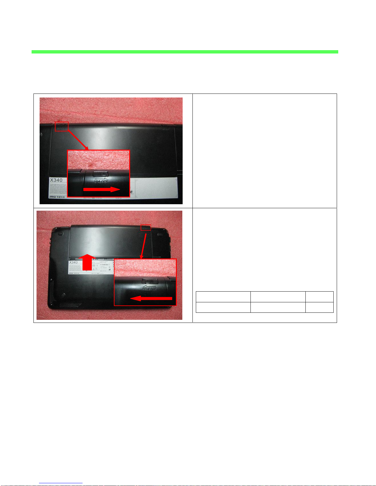
1、BATTERY PACK
1.1:Move the “Unlock’ button base on left picture
shows;
1.2:Release the “Release” button and move the
battery pack base on left picture.
Component P/N Qty
Battery Pack S9N-2141200-SB3 1
X340(MS-1352)Disassemble Guide
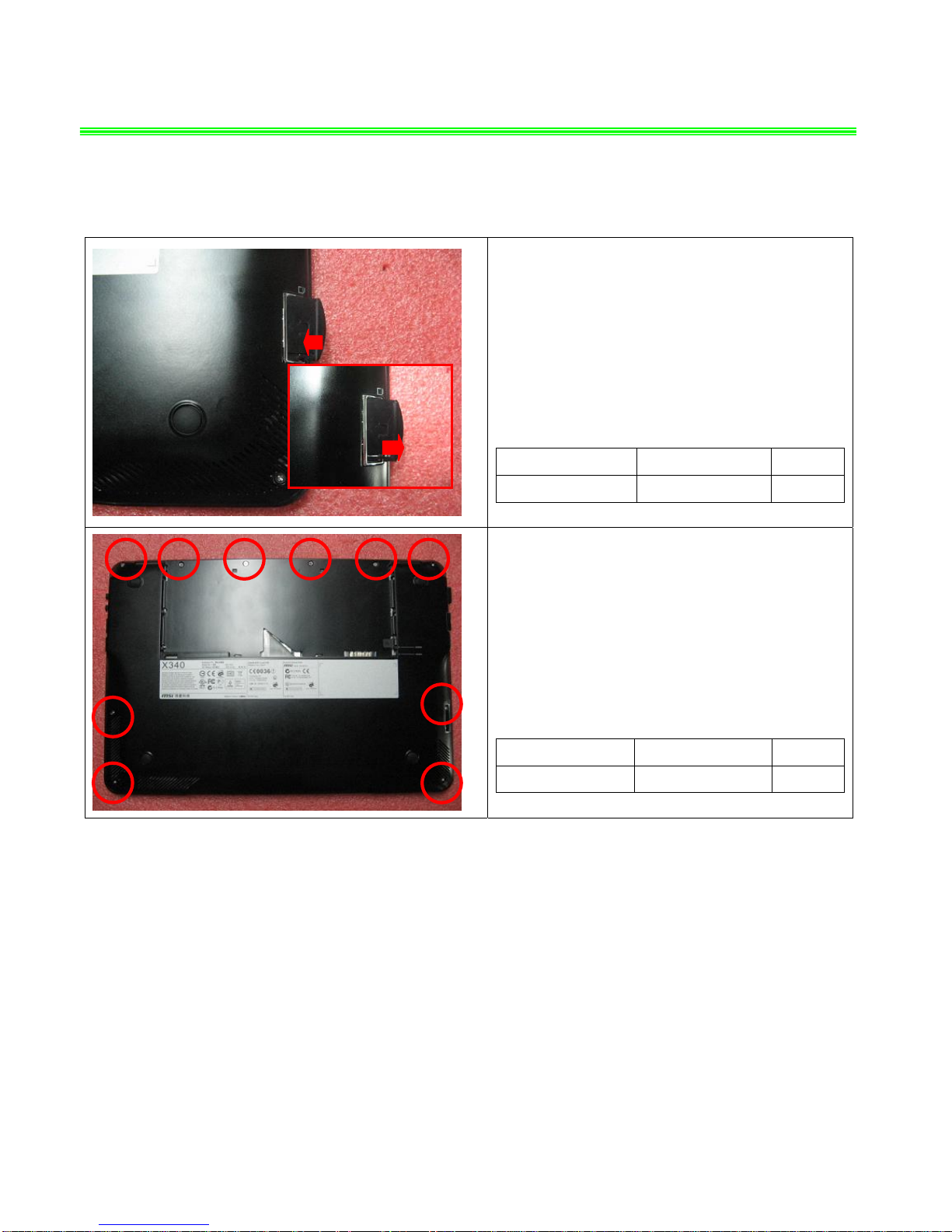
2、LOWER CASE ASSY
2.1:Push the Dummy card firstly, then remove it
after it pop up;
Component P/N Qty
Dummy Card E2P-3512611-Y31 1
2.2:Remove the 10 screws (M2*2.5mm);
Attention: the screw driver touque is: 1.5-2.0Kgf-cm
Component P/N Qty
Screw E43-1202506-H29 10
X340(MS-1352)Disassemble Guide
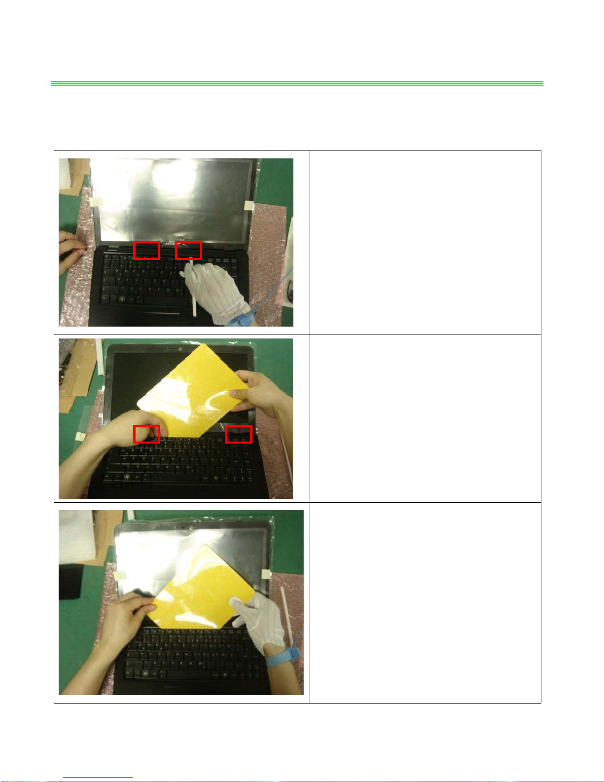
3、KEYBOARD
3.1:Before removing K/B, firstly release the 2
hooks of the middle of the keyboard upside.
3.2:Insert the stick below the keyboard
3.3:Release the 2 hooks of the two sides of the
keyboard upside, then raise upside of the keyboard

X340(MS-1352)Disassemble Guide
3、KEYBOARD
3.4:Insert the plate, then move the plate from left
to right to remove double-sided adhesive pad.
3.5:Remove the keyboard.
3.6:Firstly push the handspike on two sides of the
K/B cable connector according to the direction as
pic shows; then remove the cable;
Component P/N Qty
Keyboard S1N-1ETC211-SA0 1
X340(MS-1352)Disassemble Guide
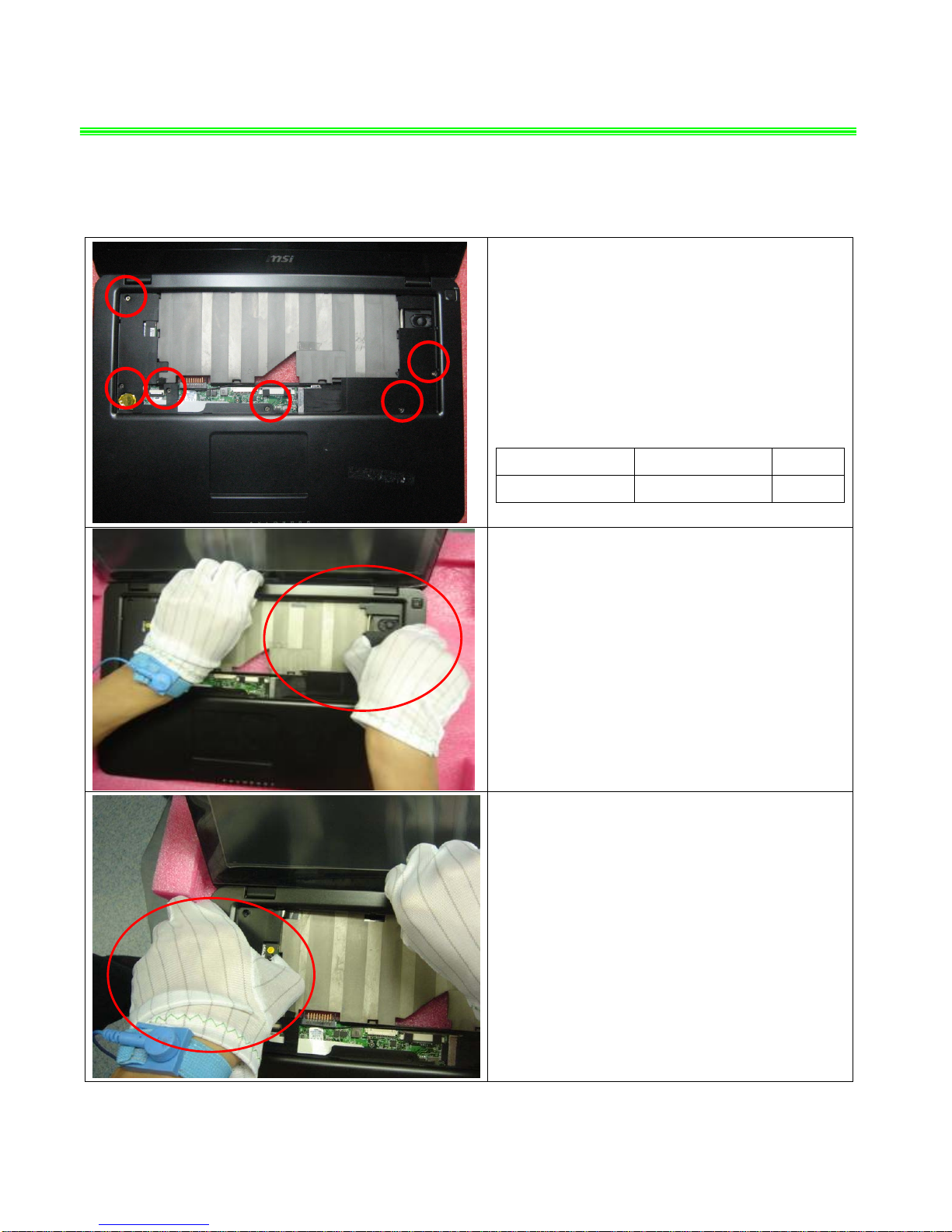
4、SEPARATE UPPER CASE AND LOWER CASE
4.1:Remove the 6 screws(M2*3.5mm);
Attention: the screw driver torque is: 1.5-2.0Kgf-cm
Component P/N Qty
Screw E43-1203501-H29 6
4.2:When remove the Upper case, firstly remove
the right side. Lift the inside of the upper with the
thumb; the other fingers push the upper to left.
4.3:Then remove the left side. Lift the inside of the
upper with the thumb; the other fingers push the
upper to right.
X340(MS-1352)Disassemble Guide
4、SEPARATE UPPER CASE AND LOWER CASE
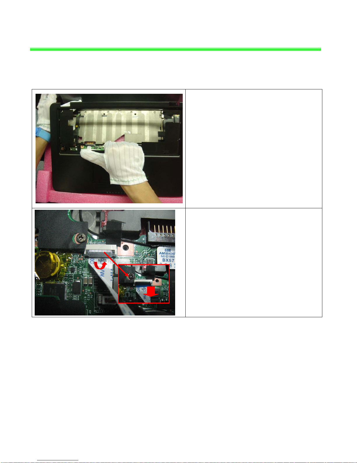
4.4:When remove the Upper case, detach the
Upper case down side from Lower case;
Attention: Don’t use the heavy strength to
pull the Upper case; and the Touchpad cable
is connected with the main board;
4.5:First release the connector that stabilize the
cable, then remove Touchpad cable according to
the direction that pic shows;
X340(MS-1352)Disassemble Guide
5、HDD MODULE
5.1:Remove the 2 screws(M2*3.5mm);
Attention: the screw driver torque: 1.5-2.0Kgf-cm
Component P/N Qty
Screw E43-1203501-H29 2
5.2:Remove the HDD Module according to the
direction as pic shows;

X340(MS-1352)Disassemble Guide
5、HDD MODULE
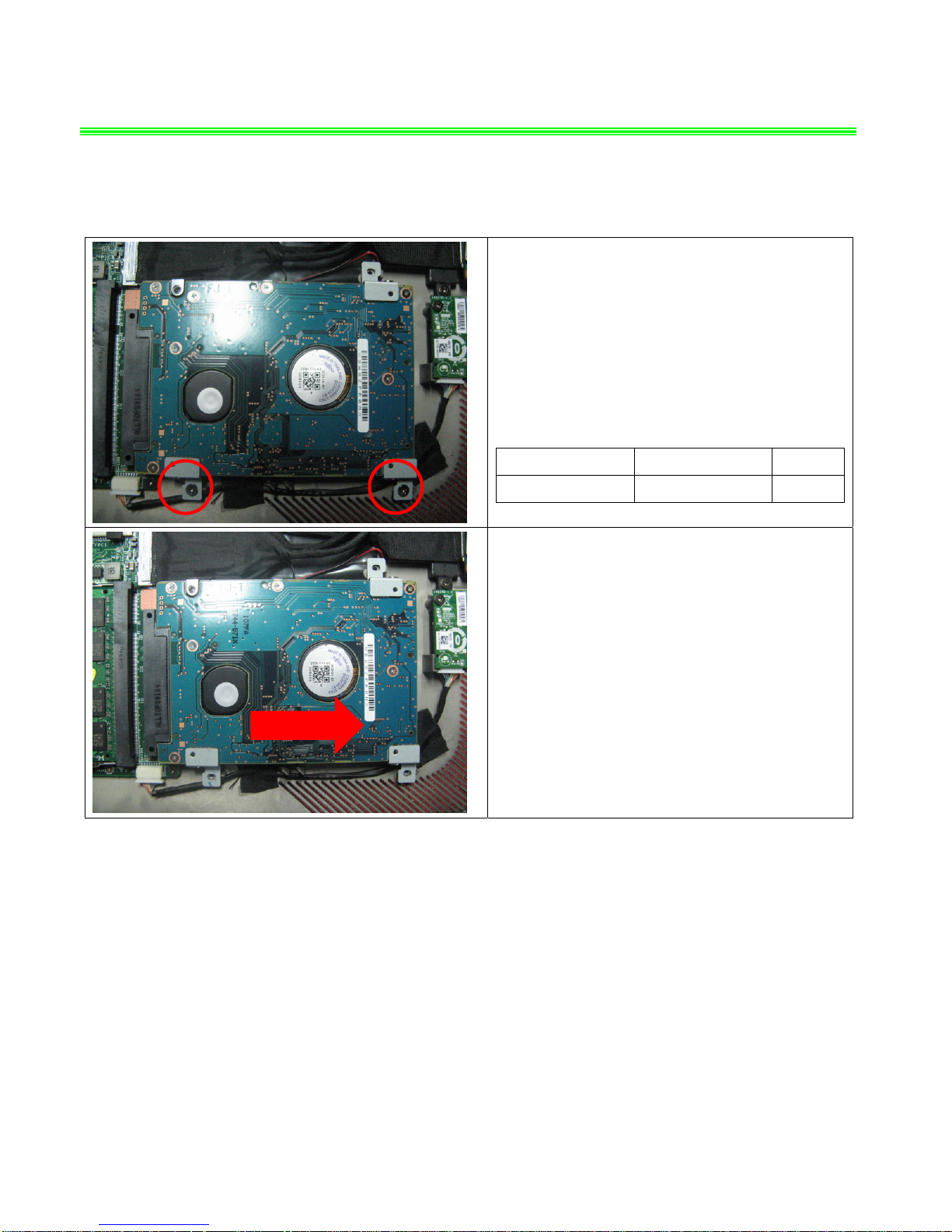
5.3:Remove the 3 screws(M3*3.5mm)
that stabilize the bracket;
Attention: the screw driver torque is 3.0-3.5Kgf-cm
Component P/N Qty
Screw E43-1303502-H29 3
5.4:Remove the 3 HDD bracket;
Component P/N Qty
HDD Bracket 307-3510611-A89 3
HDD Module S71-2432504-F06 1
X340(MS-1352)Disassemble Guide
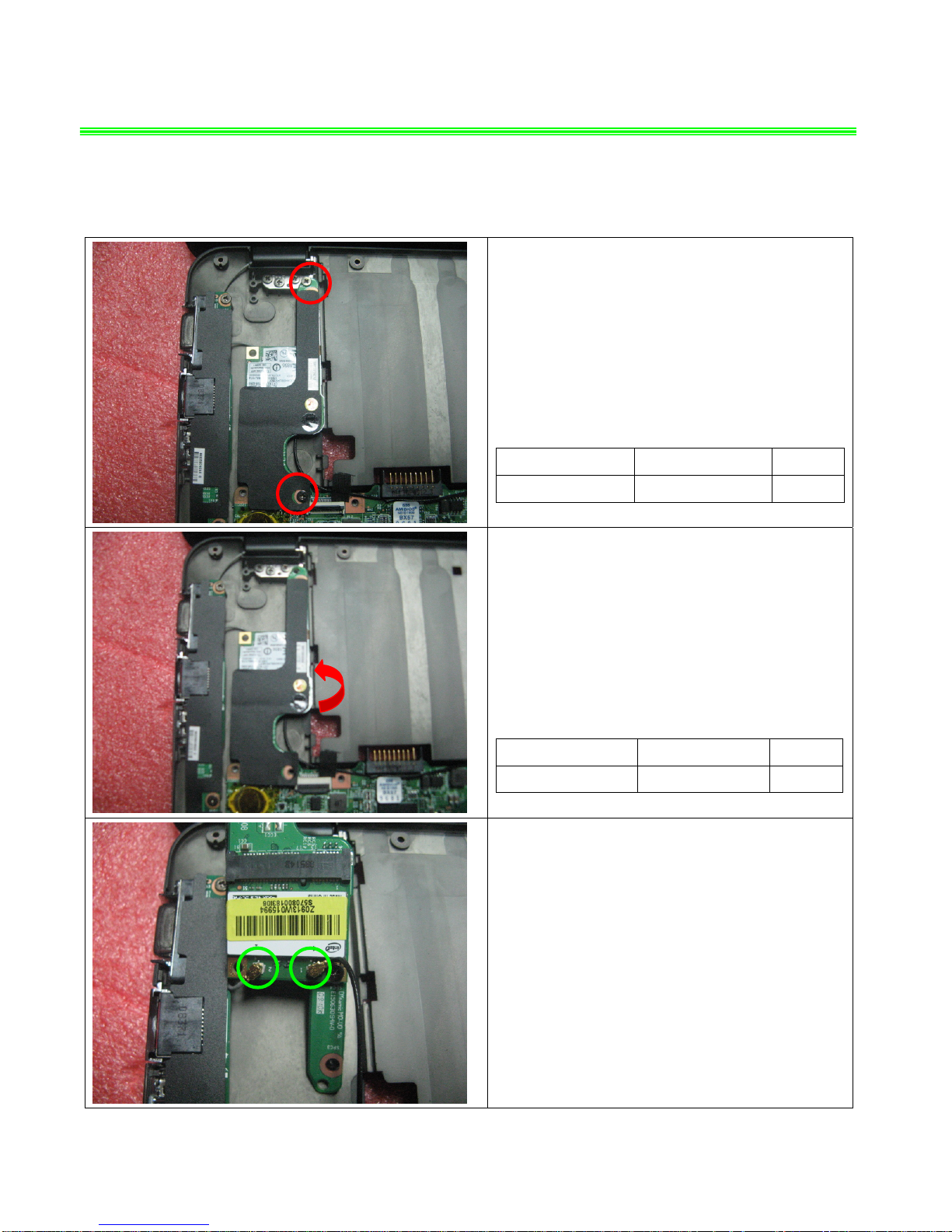
6、WLAN MODULE
6.1:Remove 2 screws(M2*3.5mm)
Attention: the screw driver torque is 1.5-2.0Kgf-cm
Component P/N Qty
Screw E43-1203501-H29 2
6.2:Remove the Wlan board as left pic shows:
Component P/N Qty
Wlan Board 607-1352P-01S 1
6.3:Remove the two side wireless card antenna
as pic shows:
X340(MS-1352)Disassemble Guide
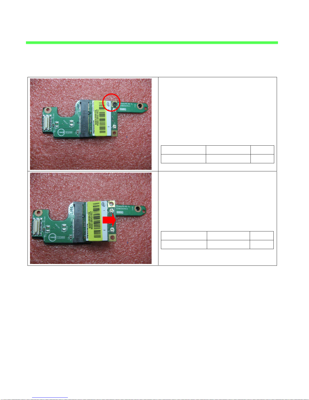
6、WLAN MODULE
6.4:Remove one screw(M2*3.5mm);
Attention: the screw driver torque is: 1.5-2.0Kgf-cm
Component P/N Qty
Screw E43-1203501-H29 1
6.5:Remove the WLAN module according to the
direction of pic shows;
Component P/N Qty
WLAN Module S57-0800183-I06 1
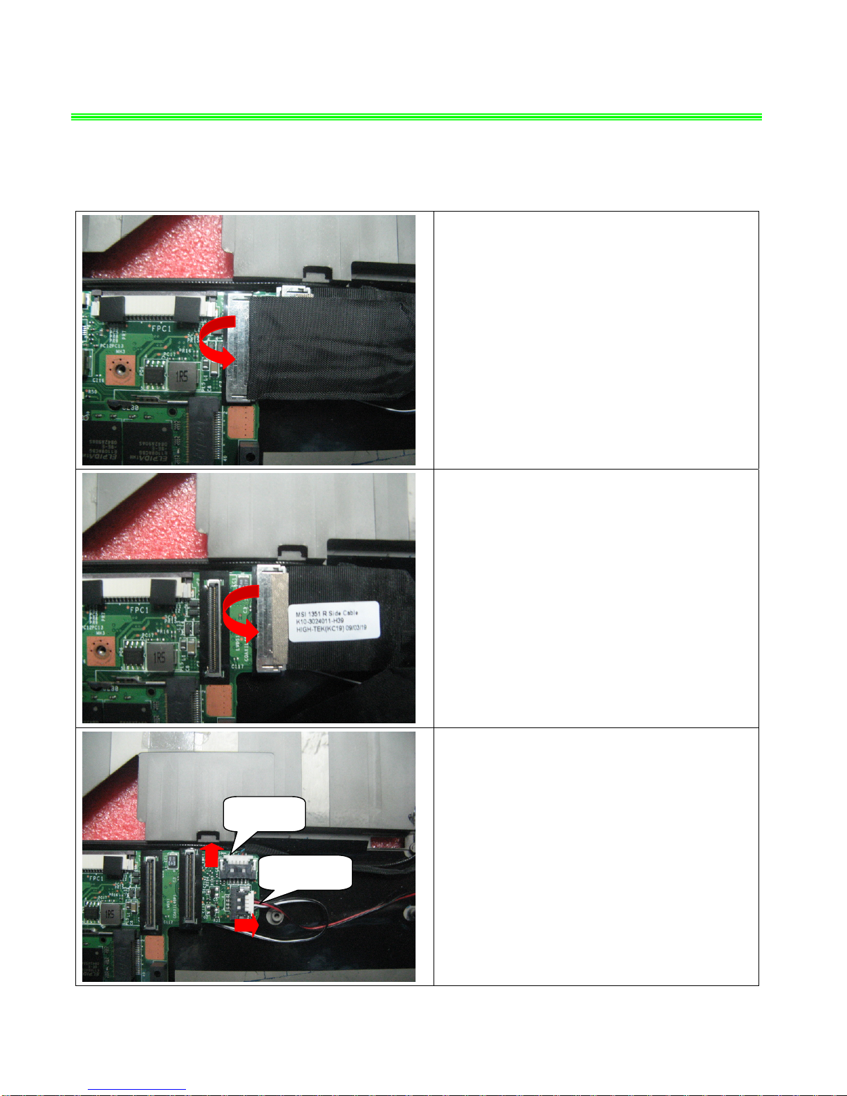
X340(MS-1352)Disassemble Guide
7、LOWER CASE ASSY-1
7.1:Remove the LVDS cable as pic shows:
7.2:Then remove the LINK cable
7.3:Remove the Speaker cable and MIC cable
separately as pic shows;
Speaker Cable
MIC Cable
 Loading...