

Page 1

GT740 (MS-1727) Assembly Guide
■ 1、LCD MODULE ASSY
■ 2、UPPER CASE ASSY
■ 3、LOWER CASE ASSY
■ 4、SEPARATE UPPER CASE AND LOWER CASE
■ 5、KEYBOARD
■ 6、THERMAL-KIT AND KEYPART
■ 7、ODD MODULE
■ 8、HDD MODULE
■ 9、BOTTOM DOOR ASSY
■ 10、BATTERY PACK
Page 2

GT740(MS-1727)Assembly Guide
1、 LCD MODULE ASSY
1.1:Assemble the WIRELESS L-Antenna board to
LCD Cover.
Component P/N Qty
L-Antenna S79-1800870-V03 1
1.2:Assemble the WIRELESS R-Antenna board to
LCD Cover.
Component P/N Qty
Antenna S79-1800860-V03
Antenna S79-1800850-V03 1
LCD Cover 307-721A413-CG0 1
1.3:Assemble the MIC.
Component P/N Qty
MIC S34-2100620-N44C 1
Page 3
GT740(MS-1727)Assembly Guide
1、 LCD MODULE ASSY
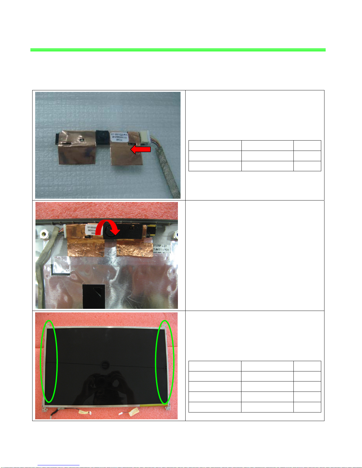
1.4:Assemble the coaxial cable(Camera Cable);
Component P/N Qty
INT Coaxial Cable K19-3036005-H39 1
Camera Module S1F-0003100-C54 1
1.5:Assemble the CMOS camera module as pic
shows;
1.6:Assemble the 8 screws (M2*3mm)
Attention: the screw driver torque is 1.5-2.0Kgf-cm
Component P/N Qty
Display Module S1J-790G003-S02 1
LCD BRACKET-L E2M-7211411-Y28 1
LCD BRACKET-R E2M-7211512-Y28 1
Screw E43-1203003-H29 8
Page 4
GT740(MS-1727)Assembly Guide
1、 LCD MODULE ASSY
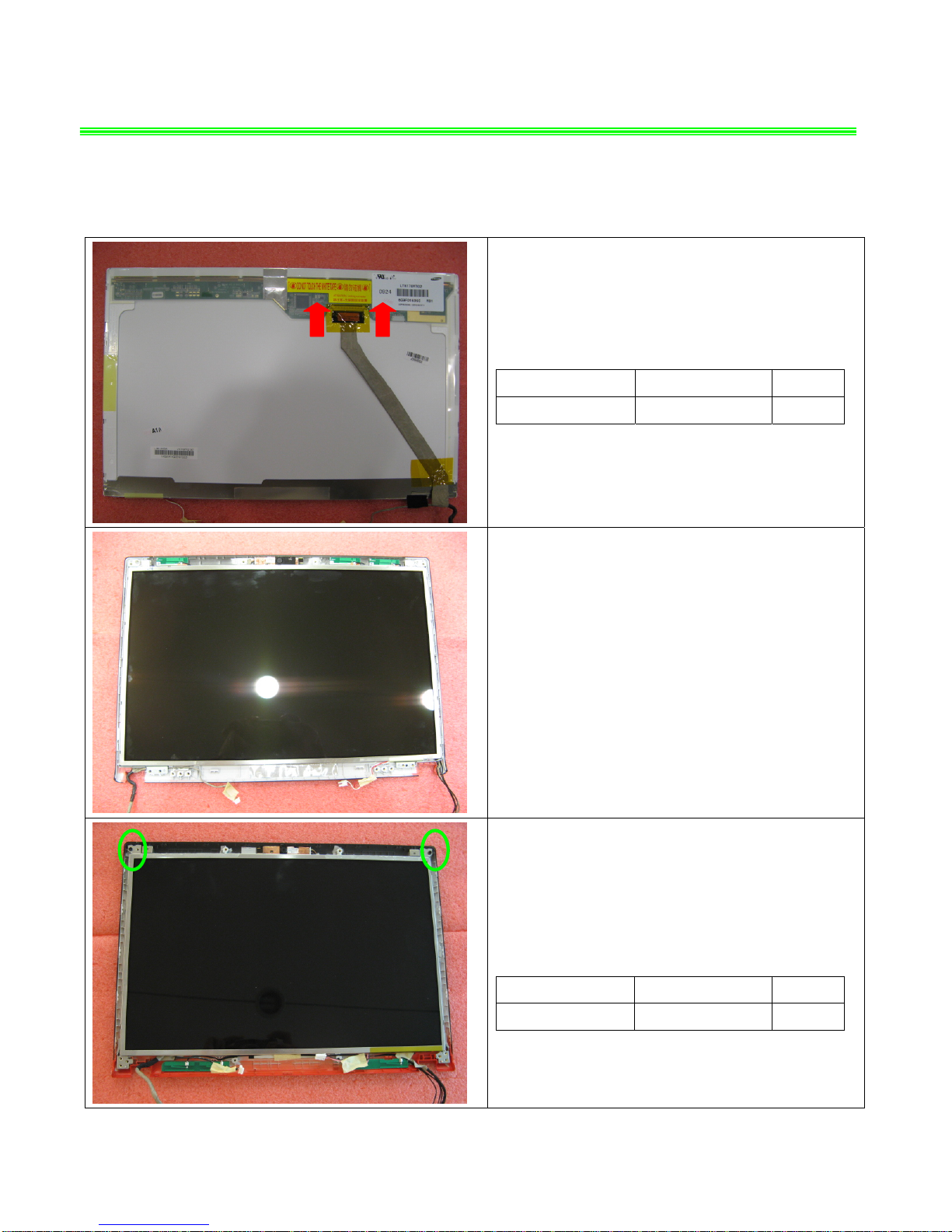
1.7:Assemble the LVDS cable to display module;
Component P/N Qty
LVDS Cable K19-3036005-H39 1
1.8:Assemble the display module to LCD cover;
1.9:Lock the 2 screws (M2.5*5mm)
Attention: the screw driver torque is 2.0-2.5Kgf-cm
Component P/N Qty
Screw E43-1255011-H29 2
Page 5
GT740(MS-1727)Assembly Guide
1、 LCD MODULE ASSY
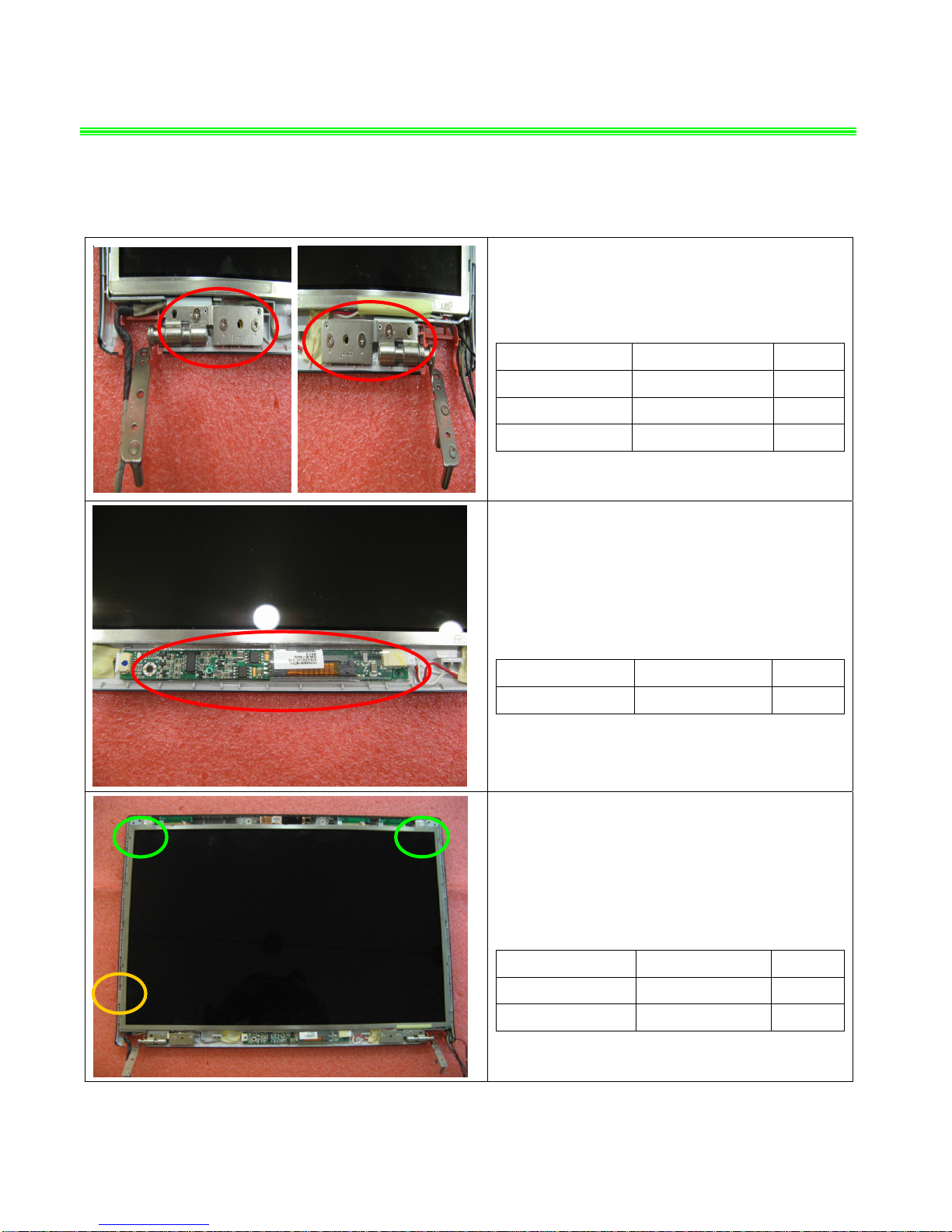
1.10Assemble the two LCD hinges on two sides;
Lock the 6 screws (M2.5*5mm);
Attention: the screw driver torque is 3.0-3.5Kgf-cm
Component P/N Qty
Screw E43-1255001-H29 6
Hinge R E2M-7211811-G60 1
Hinge L E2M-7211711-G60 1
1.11:Assemble the INVERTER
Component P/N Qty
INVERTER S78-3300290-SG3 1
1.12:Assemble the 3 magnet on LCD cover;
Component P/N Qty
LCD Cover Magnet E2Y-2210512-SF7 2
LCD Cover Magnet E2Y-6710411-SF7 1
Page 6
GT740(MS-1727)Assembly Guide
1、 LCD MODULE ASSY
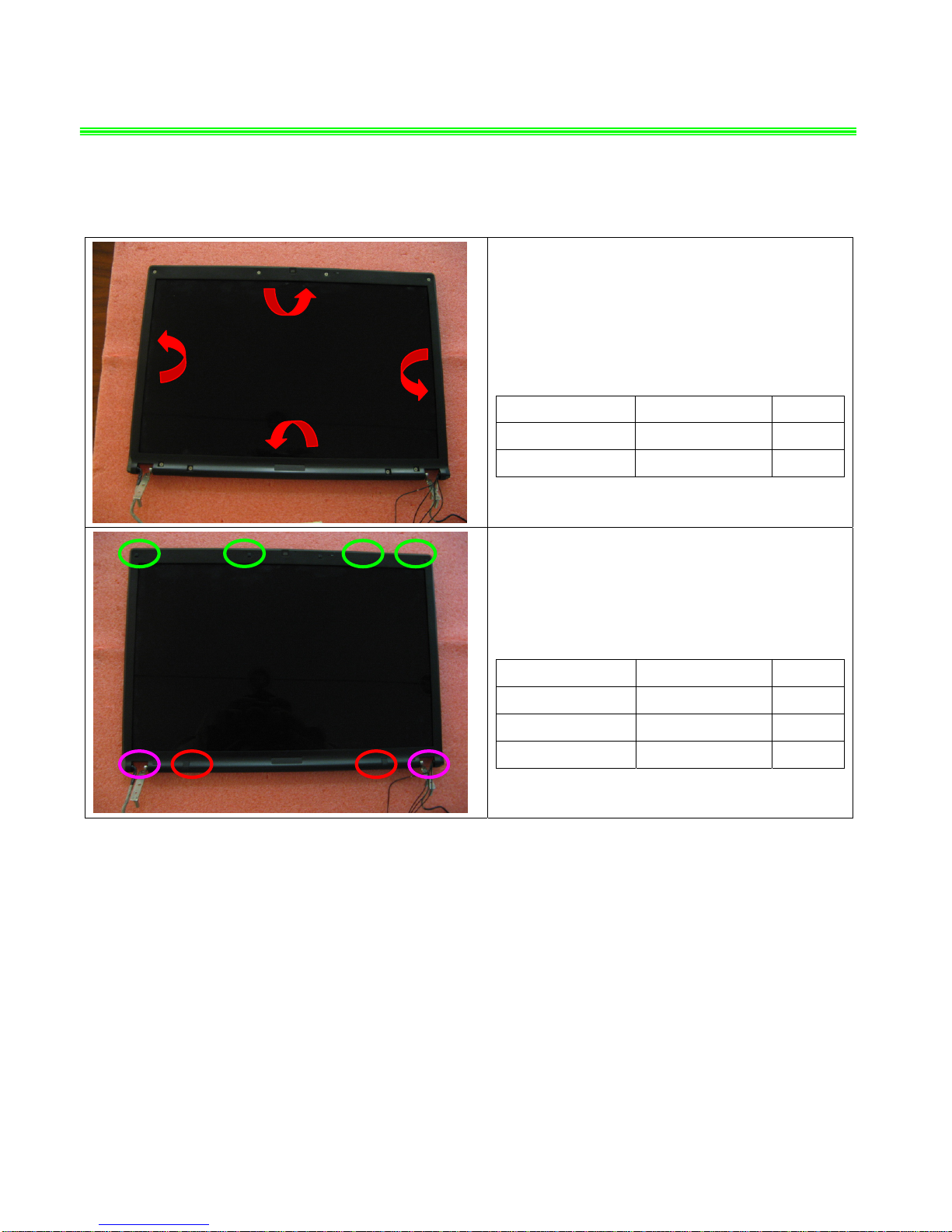
1.13:Assemble the LCD bezel, Lock the 8screw
(M2.5*5mm).
Attention: the screw driver torque is 2.0-2.5Kgf-cm
Component P/N Qty
Screw E43-I250551-H29 8
LCD Bezel 307-721B213-Y31 1
1.14:Assemble the 8 cover rubber
Component P/N Qty
UP Rubber
E2Y-6510121-Y40
4
DOWN Rubber
E2Y-7210511-Y40
2
DOWN Rubber
E2Y-7210611-Y40
2
Page 7
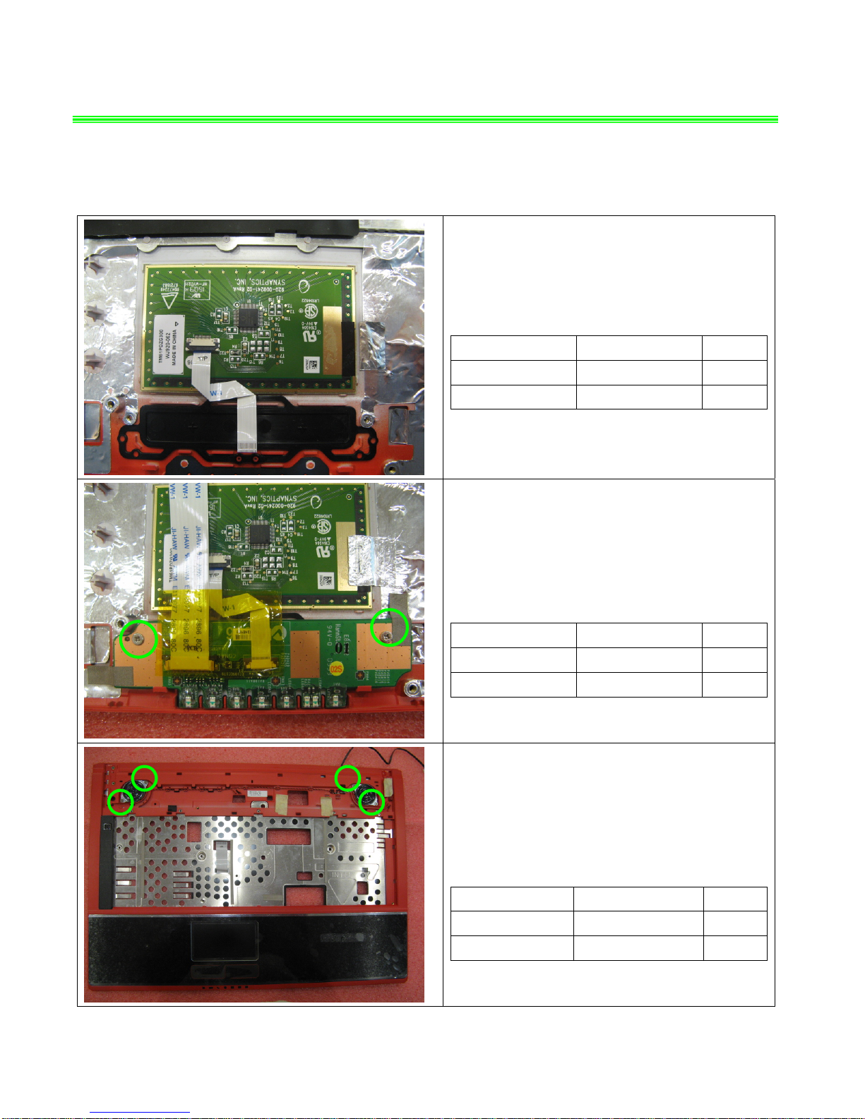
GT740(MS-1727)Assembly Guide
2、UPPER CASE ASSY
2.1:Assemble T/P module,
Component P/N Qty
Touchpad Module S78-3700360-SD2 1
Upper Case 307-721C434-Y31 1
2.2:Assemble Button board, then lock 2 screws
(M2*3mm).
Attention: the screw driver torque is 1.5-2.0Kgf-cm
Component P/N Qty
LED board 607-1727B-03S 1
screw E43-1203003-H29 2
2.3:Assemble the Speaker module to lower case;,
then lock the 4 screws (M2*3mm).
Attention: the screw driver torque is 1.5-2.0Kgf-cm
Component P/N Qty
Screw E43-1203003-H29 4
Speaker Module S33-A000500-F33 1
Page 8
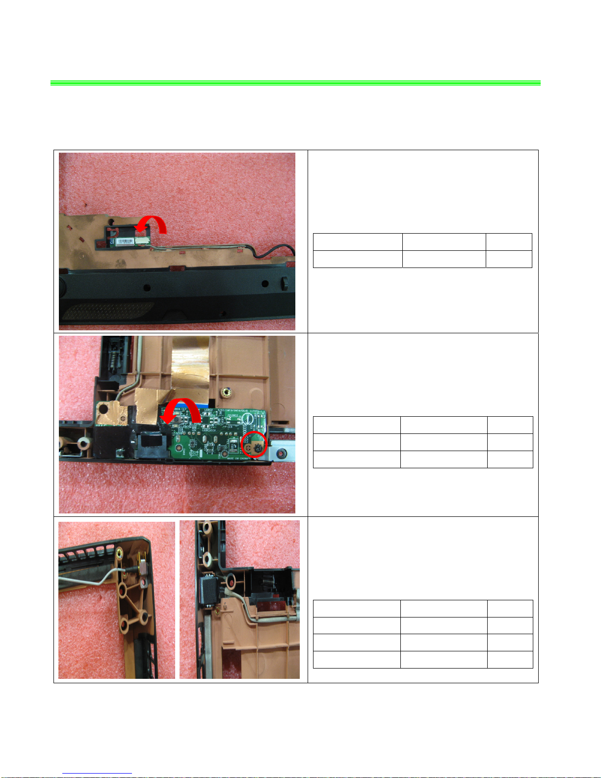
GT740(MS-1727)Assembly Guide
3、LOWER CASE ASSY
3.1:Assemble the B/T module;
Component P/N Qty
Bluetooth Module 605-3801-020 1
3.2:Lock the 1screws(M2*3mm)
Attention: the screw driver torque is 1.0-1.5Kgf-cm
Component P/N Qty
Launch board 607-1727A-04S 1
Screw E43-1203013-G68 1
3.3:Assemble the RJ11 and TV tuner cable to
Lower case;
Component P/N Qty
Lower Case 307-721D213-Y31 1
TV cable K19-3001016-H39 1
RJ11 CABLE K10-3002109-H58 1
Page 9
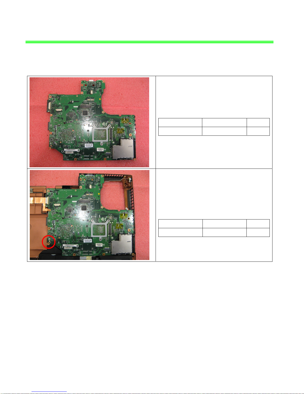
GT740(MS-1727)Assembly Guide
3、LOWER CASE ASSY
3.4: Assemble the main board to Lower case;
Component P/N Qty
Main Board 607-17271-04S 1
3.5:Lock the 1screw (M2.5*5mm)
Attention: the screw driver torque is 2.3±0.2Kgf-cm
Component P/N Qty
Screw E43-I250551-H29 1
Page 10

GT740(MS-1727)Assembly Guide
4、SEPARATE UPPER CASE AND LOWER CASE
4.1:Assemble the T/P cable.
4.2:Lock 3 screws(M2*3mm)
Attention: the screw driver torque is 1.0-1.5Kgf-cm
Component P/N Qty
Screw E43-I250551-H29 3
4.3:Lock 13 screws(M2.5*5mm).
Attention: the screw driver torque is 2.0-2.5Kgf-cm
Component P/N Qty
Screw E43-I250551-H29 13
Page 11

GT740(MS-1727)Assembly Guide
4、SEPARATE UPPER CASE AND LOWER CASE
4.4:Assemble the K/B cable;
Component P/N Qty
Keyboard S1N-3UCU131-C54 1
4.5:Lock the 5 screws(M2*3mm);
Attention: the screw driver torque is: 1.5-2.0Kgf-cm
Component P/N Qty
Screw E43-1203003-H29 5
Page 12

GT740(MS-1727)Assembly Guide
4、SEPARATE UPPER CASE AND LOWER CASE
4.6:Lock the 3 screws (M2.5*5mm) that stabilize
the hinge.
Attention: the screw driver torque is
2.0~2.5Kgf-cm
Component P/N Qty
Screw E43-I250551-H29 3
4.7:Lock the 3 screws(M2.5*5mm) that stabilize
the hinge Cap
Attention: the screw driver torque is
2.0~2.5Kgf-cm
Component P/N Qty
Screw E43-I250551-H29 3
Page 13

GT740(MS-1727)Assembly Guide
5、KEYBOARD
5.1:Assemble the LCD cable;
5.2:Assemble the Cap-sensor board.
Component P/N Qty
Sensor board 607-1727C-03S 1
Middle cover 307-723EG13-Y31 1
5.3:Assemble the Middle Cover.
Page 14

GT740(MS-1727)Assembly Guide
6、THERMAL-KIT AND KEYPART
6.1:
Assemble VGA Module as below.
Component P/N Qty
VGA 602-V167-09S 1
6.2: Lock the 2 screws (M2.5*5mm).
Attention:the screw driver torque is 1.8-2.0Kgf-cm
Component P/N Qty
Screw E43-I250551-H29 2
6.3:Assemble Modem. then lock the 2 screws
(M2*3mm)
Attention:the screw driver torque is 1.5-2.0Kgf-cm
Component P/N Qty
Screw E43-1203003-H29 2
Modem S52-2801210-C59 1
Page 15

GT740(MS-1727)Assembly Guide
6、THERMAL-KIT AND KEYPART
6.4:Assemble the RAM module according the
direction as pic shows;
Component P/N Qty
RAM Module S7C-S357701-T10 2
6.5:Assemble the WLAN module according to the
direction of pic shows;
Component P/N Qty
WLAN Module 605-6896-010 1
6.6:Lock 1 screw(M2*3mm); then assemble the
two side wireless card antenna as pic shows:
Attention: the screw driver torque is: 1.5-2.0Kgf-cm
Component P/N Qty
Screw E43-1203003-H29 1
Page 16

GT740(MS-1727)Assembly Guide
6、THERMAL-KIT AND KEYPART
6.7:
Open the CPU Slot with Screw Driver, then
lock CPU Module
as below.
Component P/N Qty
CPU A09-16200R6-I06 1
6.8: Assemble the Fan, after that Lock the 4 spring
screws, then lock the 3 screws (M2.5*5mm).
Attention:the screw driver torque is 2.0-2.5Kgf-cm
Component P/N Qty
Screw E43-I250551-H29 3
Fan E33-0800050-F05 1
4 6
7
3
5
2 1
Page 17

GT740(MS-1727)Assembly Guide
7、ODD MODULE
7.1:
Assemble ODD Bracket as below, Then lock
2pcs Screws(M2*3mm);
Attention: the screw driver torque: 2.0-2.5Kgf-cm
Component P/N Qty
Screw E43-1203003-H29 2
ODD Bracket E2M-7210611-Y31 1
ODD Module S7D-2270001-SI4 1
7.2:
Assemble ODD Bezel as below.
Component P/N Qty
ODD Bezel 307-721B213-Y31 1
7.3:Assemble the ODD Module according to the
direction as pic shows.
Page 18

GT740(MS-1727)Assembly Guide
8、HDD MODULE
8.1:Assemble the HDD bracket;
Component P/N Qty
HDD Bracket E2M-2211511-Y28 1
HDD Module S71-2432501-W36 1
8.2: Assemble the 2 screws (M3*3.5mm) that
stabilize the bracket;
Attention: the screw driver torque is 2.0-2.5Kgf-cm
Component P/N Qty
Screw E43-1303501-G68 2
Page 19

GT740(MS-1727)Assembly Guide
8、HDD MODULE
8.3:Assemble the HDD Module according to the
direction as pic shows;
8.4:Lock the 2 screws(M2.5*5mm);
Attention: the screw driver torque: 2.0-2.5Kgf-cm
Component P/N Qty
Screw E43-I250551-H29 2
Page 20

GT740(MS-1727)Assembly Guide
9、BOTTOM DOOR ASSY
9.1:Assemble the Bottom door, then lock the 5
screws (M2.5*5mm).
Attention: the screw driver touque is: 2.0-2.5Kgf-cm
Component P/N Qty
Bottom door 307-721J212-Y31 1
Screw E43-I250551-H29 5
Page 21

GT740(MS-1727)Assembly Guide
10、BATTERY PACK
10.1:Release the “Release” button and assemble
Battery Pack in the direction of arrow in the left
picture. Shift Unlock button to lock Battery Pack.
Component P/N Qty
Battery Pack S9N-1564221-M47 1
Page 22

GT740(MS-1727)screws specification
Photo Screw specification Label
(M2.5*L5MM)black
(M2*L3MM)black
(M2*L3MM)white
(M3*L3.5MM) white
Page 23

GT740(MS-1727)screws specification
■ 1、BOTTOM DOOR ASSY total 20pcs screws,
■ specification:
Photo Screw specification label
(M2.5*L5MM) black
Page 24

GT740(MS-1727)screws specification
■ 2、WIRELESS CARD and HDD ASSY total 5pcs screws,
■ specification:
Photo Screw specification label
(M3*L3.5MM) white
(M2*L3MM)white
Page 25

GT740(MS-1727)screws specification
■ 3、LCD HINGE total 3pcs screws ,
■ specification:
Photo Screw specification Label
(M2.5*L5MM) black
Page 26

GT740(MS-1727)screws specification
■ 4、UP CASE total 9pcs screws ,
■ specification:
Photo Screw specification Label
(M2*L3MM)white
Page 27

GT740(MS-1727)screws specification
■ 5、LCD BEZEL total 8pcs screws,
■ specification:
Photo Screw specification label
(M2.5*L5MM) black
Page 28

GT740(MS-1727)screws specification
■ 6、LCD MODULE ASSY total 16pcs screws ,
■ specification:
Photo Screw specification label
(M2.5*L5MM) black
(M2*L3MM)white
Page 29

GT740(MS-1727)screws specification
■ 7、NB total 1pcs screw.
■ specification:
Photo Screw specification label
(M2.5*L5MM) black
Page 30

GT740(MS-1727)screws specification
■ 8、LOWER CASE total 3pcs screws,
■ specification:
Photo Screw specification label
(M2*L3MM) white
(M2*L3MM) black
 Loading...