

MSI MS-1035, MS-1022 Installation Manual
Index
Overview
Step 1: Installing CPU
Step 2: Installing CPU Heat Sink and Fan
Step 3: Installing Notebook Memory
Step 4: Installing Mini PCI WLAN Card
Step 5: Installing Notebook Hard Drive (HDD)
Step 6: Installing the Battery
Step 7: Final Check
Step 8: Entering BIOS
p. 1
p. 3
p. 3
p. 5
p. 6
p. 7
p. 9
p. 10
p. 11
Installation Guide
Copyright®2006 MSI Computer Corp.
Overview
MS-1035 is shipped out as a bare bone. Some of the components are
equipped while some are not. This installation guide provides you with the
information of notebook hardware setup. Before assembling your Notebook,
please prepare for the installation tools and appropriate items. If you are not
clear about the items, please contact your dealer for more information.
Package check list
Optional Hardware Devices:
HDD, Mini PCI WLAN card, CPU, Memory
Before you install your Notebook
•
•
•
Warning!
•
•
•
•
The peripheral devices contained herein depend on your actual system
configuration.
Third-party trademarks and names are the properties of their respective
owners.
The information contained herein relevant to software and hardware are for
reference only and in accordance with actual system configuration. All
information are subject to change without notice.
Ensure power is turned off and Notebook Battery is removed before you
install any hardware devices.
Use a grounded wrist strap before handling computer components such as
CPU, Memory, HDD, mini-PCI Card, etc.
Place components (CPU, Memory, HDD, mini-PCI Card, etc) on a grounded
antistatic pad or on the bed that came with the components whenever the
components are separated from the Notebook.
If there are any difficulties installing hardware devices, please contact your
dealer for further information.
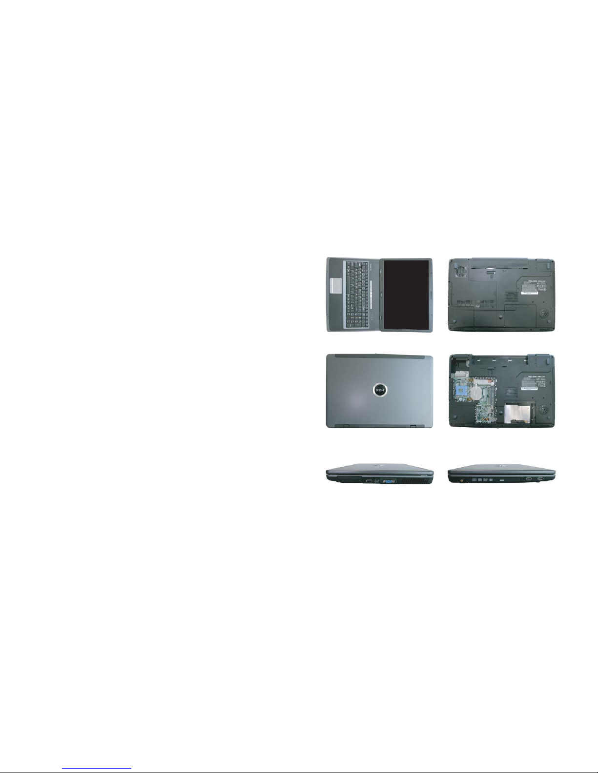
Open View
1. Cover latch
2. Display Panel
3. Quick Launch Buttons and Power button
4. Status LEDs
5. Keyboard
6. Touchpad
7. Stereo Speakers
Front View Rear View
Right View Left View
Bottom View
1. CPU Compartment
2. Mini PCI Drive Compartment
3. Memory Compartment
4. Hard Disk Drive Compartment
5. Battery Unlock Button
6. Battery Pack
p. 1 p. 2
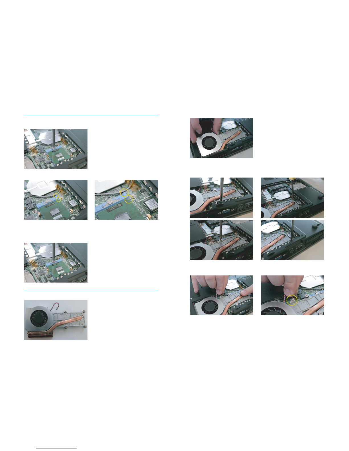
2-2 Slide the CPU Heat Sink and Fan assembly over the CPU !! Be sure that there are
no wires underneath the Heat Sink !!
2-3 a.b.c.d. Align the four screws with the screw holes next to the CPU. May need to
slide the Heat Sink to the side to align. Tighten the four screws in a diagonal
direction. !! Improper connection of the CPU heat sink will damage the notebook
and CPU !!
2-4 Plug the CPU fan connector before positioning the fan. !! Connect the wires
correctly. There is only one way to connect. DO NOT force in !! Warning: failure to
connect the fan may cause damage to the notebook and CPU !!
Step 1 : Installing CPU
1-1 Prepare a proper size flat head screw driver. Un-screw the screw until it can not
go any further
1-2 Locate the golden cut edge on the CPU’s upper right-hand corner. Then insert the
CPU into the socket. !! The CPU will only fit in the coorect orientation !!
1-3 Adjust the CPU socket by turning the screw. Make sure the CPU is properly
installed. Then press the CPU evenly by hand and turn the screw using a flat head
screw driver to lock the CPU in place. !! Please make sure the golden cut edge
location is aligned with the notch of the CPU socket. If the CPU does not align with
the CPU socket, it will damage the CPU !!
Step 2 : Installing CPU Heat Sink and Fan
2-1 Use the Heat Sink and Fan that is provided
p. 3 p. 4
a. b.
c. d.
 Loading...