

Page 1

Installation Guide
Copyright © 2005 MSI Computer Corp.
Page 2

Overview:
MS-1029 is shipped out as a bare bone. Some of the components are equipped while some are not. This
installation guide provides you with the information of notebook hardware setup. Before assembling your
Notebook, please prepare for the installation tools and appropriate items. If you are not clear about the
items, please contact your dealer for more information.
Package check list:
Optional Hardware Devices:
HDD, Mini PCI WLAN card, CPU, Memory
Before you install your Notebook
• The peripheral devices contained herein depend on your actual system configuration.
• Third-party trademarks and names are the properties of their respective owners.
• The information contained herein relevant to software and hardware ar e for reference only and in
accordance with actual system configuration. All information are subject to change without notice.
Warning!
• Ensure power is turned and Notebook Battery is removed before you install any hardware
devices.
• Use a grounded wrist strap before handling computer components such as CPU, Memory, HDD,
mini-PCI Card, etc.
• Place components (CPU, Memory, HDD, mini-PCI Card, etc) on a grounded antistatic pad or on
the bed that came with the components whenever the components are separated from the
Notebook.
• If you have any difficulties in installing hardware devices, please contact your dealer for further
information.
Open View
1. Cover latch
2. Display Panel
3. Quick Launch Buttons and Power button
4. Status LEDs
5. Keyboard
6. Touchpad
7. Stereo Speakers
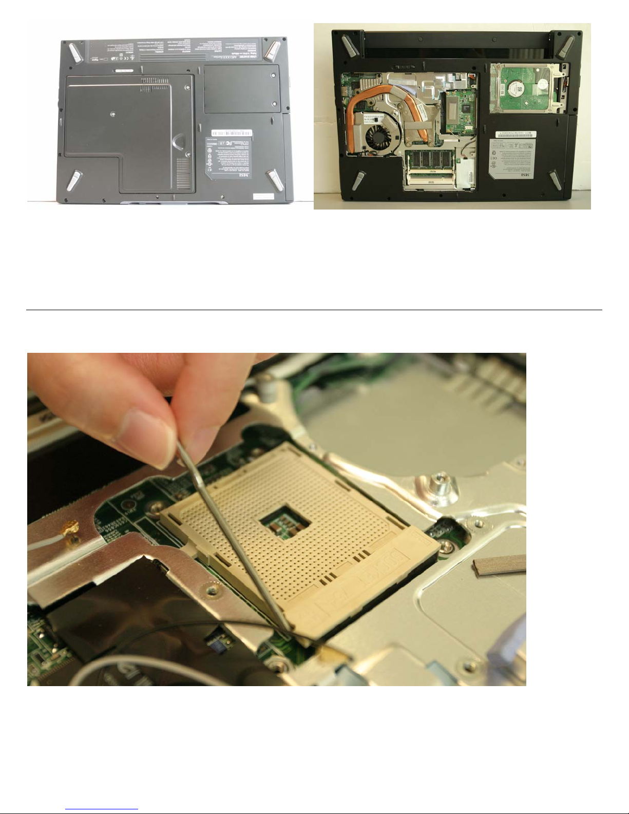
Bottom View
1. CPU Compartment
2. Mini PCI Drive Compartment
3. Memory Compartment
4. Hard Disk Drive Compartment
5. Battery Unlock Button
6. Battery Pack
Page 3
Right view
Left view
Rear view
Others:
Step 1: Installing CPU
1-1 Pull the CPU socket handle sideways away from the socket and then raise the lever up to a 90-
degree angle.
Page 4
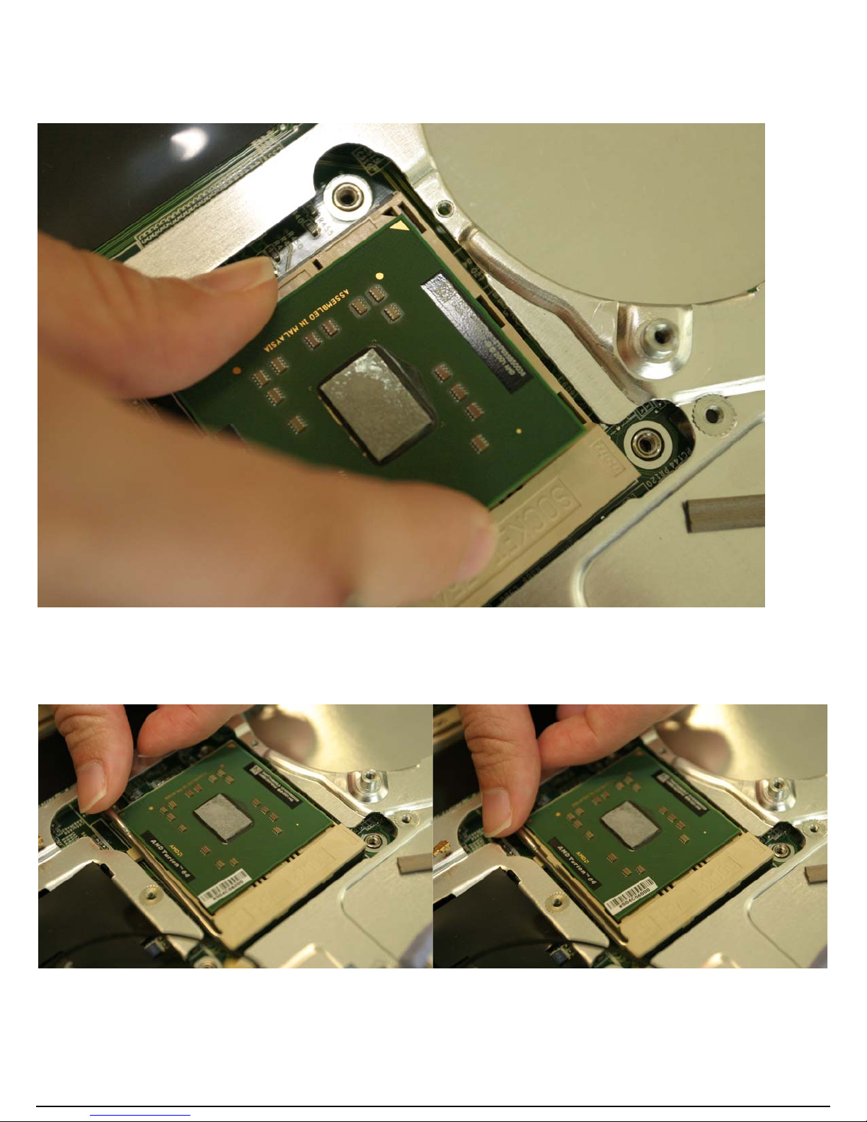
1-2 Carefully align the processor using the gold arrow marking on the substrate of the FC-PGA2 package
and the socket for reference.
!!!The CPU only fit in the correct orientation!!!
1-3 Taking care not to bend any of the processor pins, carefully insert the processor into the socket. Hold
the CPU down firmly with one hand and close and secure the socket lever with the other.
!!! Please make sure the golden cut edge location is aligned with the notch of the CPU socket. If
the CPU does not align with the CPU socket, it will damage the CPU!!!
Page 5
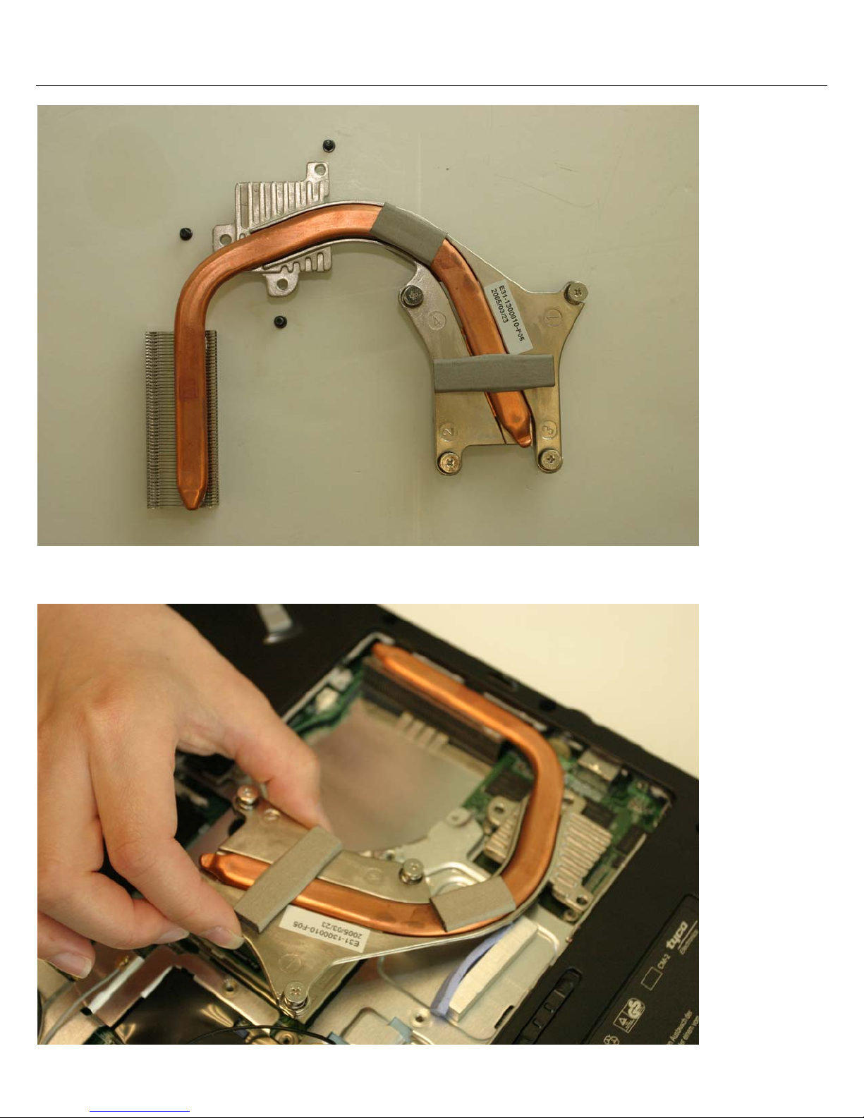
Step 2: Installing CPU Heat Sink
2-1 Please use the given CPU heat sink (refer to Figure 2-1)
Hint: We recommend you to apply the given thermal grease for better heat conduction between
your CPU and heat sink.
2-2 Align the CPU heat sink in the correct direction.
Page 6

2-3 a.b.c Slide the golden part of the heat sink and align total of 7 screws (4 screws on the CPU heat
sink and 3 screws along the mechanism) properly before locking down the nuts.
2-4a.b.c.d Lock down the heat sink diagonally or according to “1-2-3-4” shown on the CPU heat sink.
!!!Improper to lock the CPU heat sink nuts will damage the CPU !!!
Hint: Please check the heat sink and make sure it is in good contact with the CPU before you turn
on your notebook.
!!! Poor contact will cause overheat and may damage your CPU!!!
Page 7

2-5 Please use the given CPU heat sink fan (refer to Figure 2-6)
2-7 Plug the CPU heat sink fan connector first before you position the fan.
!!! Improper connection of the CPU heat sink fan and/or without pluging the fan connector will
damage the notebook and CPU!!!
Page 8

2-8 Position the fan in the proper location.
2-9 a.b.c Lock down the CPU heat sink fan by using the given 3 screws.
Page 9

Step 3: Installing Notebook Memory
3-1 Align the memory module to the DIMM socket 1.
3-2 Push down the memory module gently until the metal-locking levers aside from the DIMM socket 1 is
fastened.
!!! Memory module can only fit in one direction due to the keyed notch. Wrong orientation will
cause improper installation and may damage the memory modules or DIMM sockets!!!
Page 10

3-3 If you have more than one memory module, please align the 2nd memory module to the DIMM
socket 2.
3-4 Push down the memory module gently until the metal-locking levers aside from the DIMM socket 2 is
fastened.
!!! Memory module can only fit in one direction due to the keyed notch. Wrong orientation will
cause improper installation and may damage the memory modules or DIMM sockets!!!
Page 11

Step 4: Installing Mini PCI WLAN Card
4-1 Align the Mini PCI Card to the Mini PCI socket.
4-2 Adjust the attached antennas and push down the Mini PCI Card gently until the metal-locking levers
aside from the Mini PCI socket is fastened.
Page 12

!!! Mini PCI Card can only fit in one direction due to the keyed notch. Wrong orientation will cause
improper installation and may damage the Mini PCI card or Mini PCI socket!!!
4-3a.b Connect 3 antennas on Mini PCI card.
4-4 a.b.c.d.e After installing the heat sink, fan, memory and mini PCI WLAN card, slide the cover and
gently press down the cover. Lock down the cover by applying 3 screws.
Page 13

Step 5: Installing Notebook Hard Drive (HDD)
Page 14

5-1 Please use the given HDD shielding tray (refer to Figure 5-1)
5-2 Insert the HDD sideway to the given HDD shielding tray.
!!!Improper alignment will cause the damage to the HDD and the Notebook!!!
5-3 Slide the semi-finished goods (HDD+ HDD shielding tray) into HDD bay. Make sure you cannot see
the HDD label after you slide the semi-finished goods (HDD+ HDD shielding tray) into HDD bay.
Page 15

!!! There is only 1 correct alignment and orientation in sliding semi-finished goods (HDD + HDD
shielding tray)!!!
!!!Improper alignment will cause the damage the to the HDD and the Notebook!!!
5-4 After proper alignment, use both thumbs to push in semi-finished goods assembly (HDD+ HDD
shielding tray) into HDD bay.
!!! HDD Plastic puller has to face up!!!
5-5 a.b.c.d Apply given 4 screws in order to fix the HDD assembly.
Page 16

!!! Failure to apply any screw may cause HDD assembly to fall off in Notebook HDD area and will
damage the HDD and the Notebook!!!
5-6 a.b.c. After installing the HDD, slide the cover and gently press down the cover. Lock down the cover
by applying 2 screws.
!!! Failure to apply 2 screws may cause HDD assembly to fall off in Notebook HDD area and will
damage the HDD and Notebook!!!
Page 17

Step 6: Installing the Battery
6-1 Align battery to the battery slot and push down the battery gently.
Hint: If you wish to remove the battery, make sure the battery locking mechanism is in “Unlock”
position.
Page 18

Step 7: Final Check
7-1 Check all steps and make sure to fasten all the components and screws before powering on your
Notebook.
!!! Improper installation of any device(s) and loosen screws may damage the Notebook after
powering on the notebook!!!
Hint: If you are unable to power on your notebook after following the above procedure, or if there
are any other issues, please contact your local retailer or national distributor for help.
Step 8: Entering BIOS
Before powering on the Notebook, plug in Notebook power adapter into the Notebook. After pressing the
power button, press <Del> immediately which will take you to the BIOS CMOS Setup Screen.
8-1 Adjust proper TIME by pressing <Enter>. Use <+> or <-> to configure System time.
Page 19

8-2 Under “BOOT” menu in the BIOS Setup Utility, press <Enter> to select the first boot device.
8-3 Insert a Bootable OS CD into the OSD tray.
8-4 To save/ exit the BIOS Setup Screen, press “Y” to save/ exit.
8-5 After seeing the Intel Logo, immediately press “Enter” in order to install OS and follow the given
setup messages.
8-6 After installing OS, insert the given Driver CD to install the appropriate drivers in order.
Hint: If you have any questions related to the BIOS Setup procedure or if there are any other
issues, please contact your local retailers or national distributors for further support.
 Loading...