

Page 1
Quick Start
Thank you for purchasing the MSI® MPG Z390I GAMING EDGE AC motherboard.
This Quick Start section provides demonstration diagrams about how to install your
computer. Some of the installations also provide video demonstrations. Please link to
the URL to watch it with the web browser on your phone or tablet. You may have even
link to the URL by scanning the QR code.
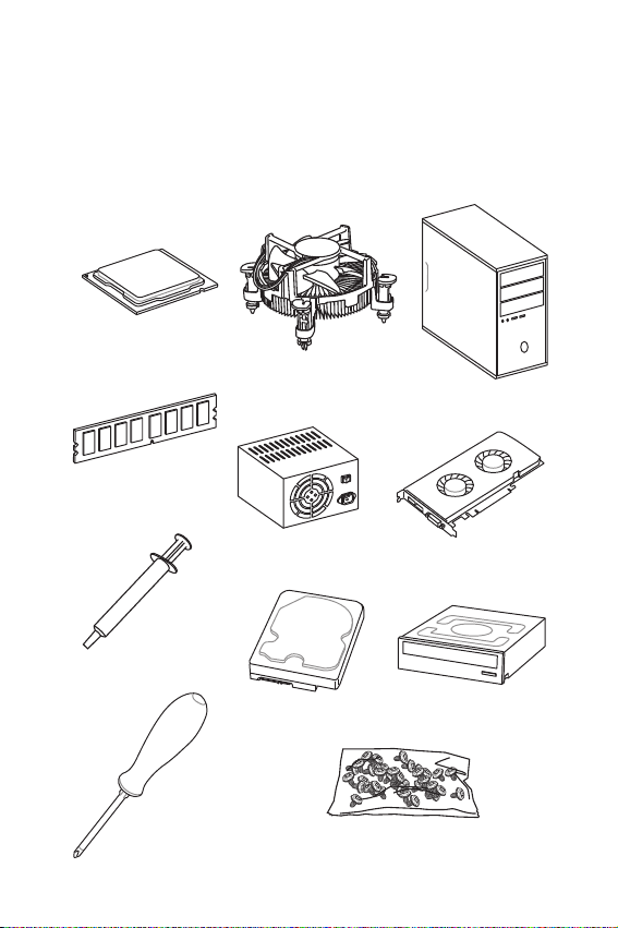
Preparing Tools and Components
Intel® LGA 1151 CPU
CPU Fan
Chassis
DDR4 Memory
Thermal Paste
Phillips Screwdriver
Power Supply Unit
SATA Hard Disk Drive
Graphics Card
SATA DVD Drive
A Package of Screws
Quick Start
1
Page 2
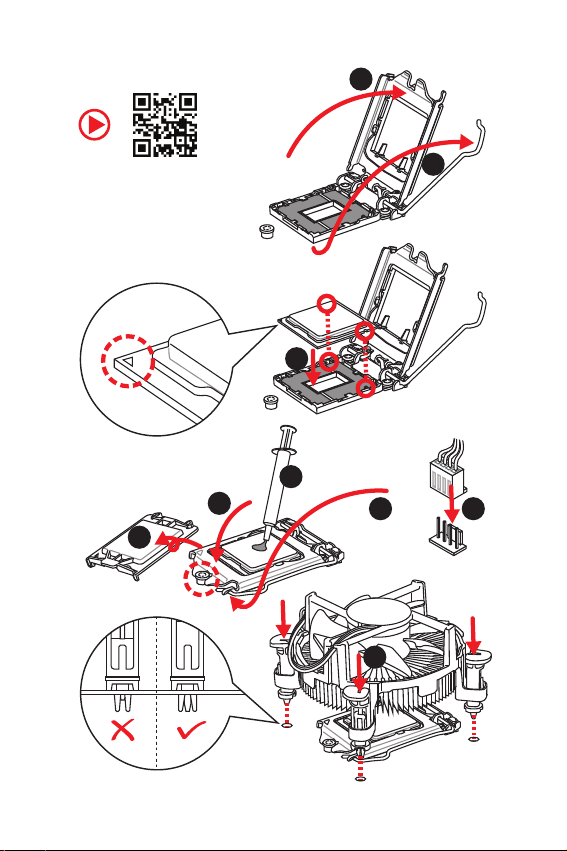
Installing a Processor
2
https://youtu.be/4ce91YC3Oww
6
1
3
7
4
5
9
8
2
Quick Start
Page 3
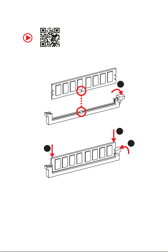
Installing DDR4 memory
http://youtu.be/T03aDrJPyQs
1
2
2
3
Quick Start
3
Page 4
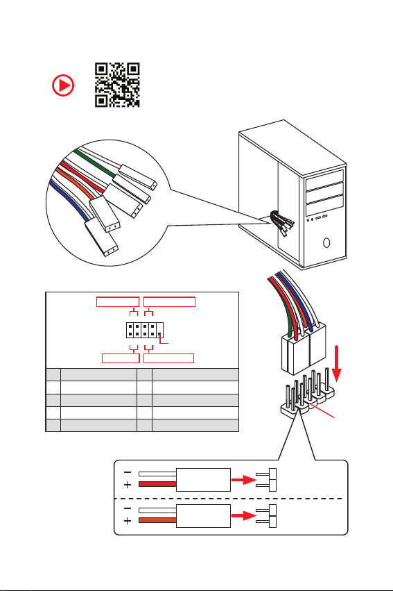
Connecting the Front Panel Header
RESET SW
POWER SW
POWER LED+
POWER LED-
HDD LED
http://youtu.be/DPELIdVNZUI
Power LED
JFP1
Power Switch
+++-
--
-
210
1
+
HDD LED Reset Switch
1 HDD LED + 2 Power LED +
3 HDD LED - 4 Power LED -
5 Reset Switch 6 Power Switch
7 Reset Switch 8 Power Switch
9 Reserved 10 No Pin
Quick Start
4
9
Reserved
HDD LED
POWER LED
HDD LED
HDD LED HDD LED +
POWER LED POWER LED +
RESET SW
JFP1
Page 5
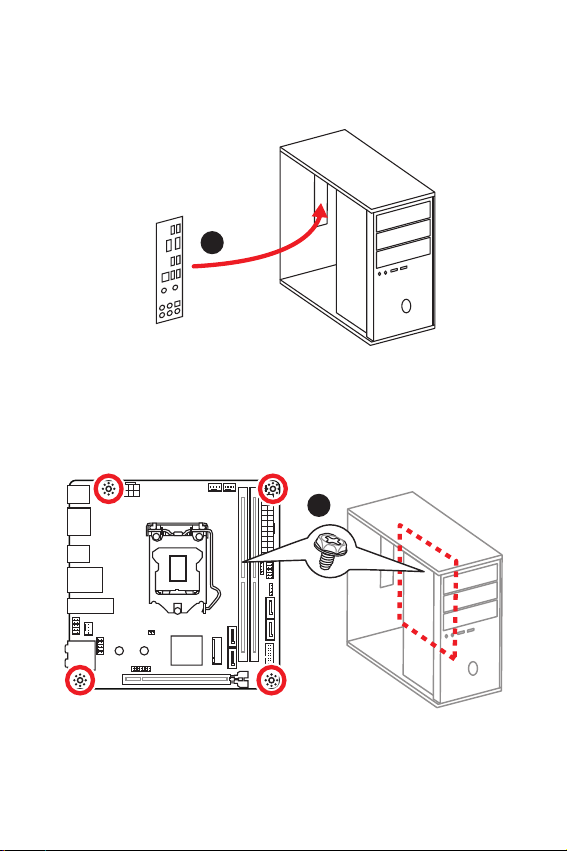
Installing the Motherboard
1
2
Quick Start
5
Page 6
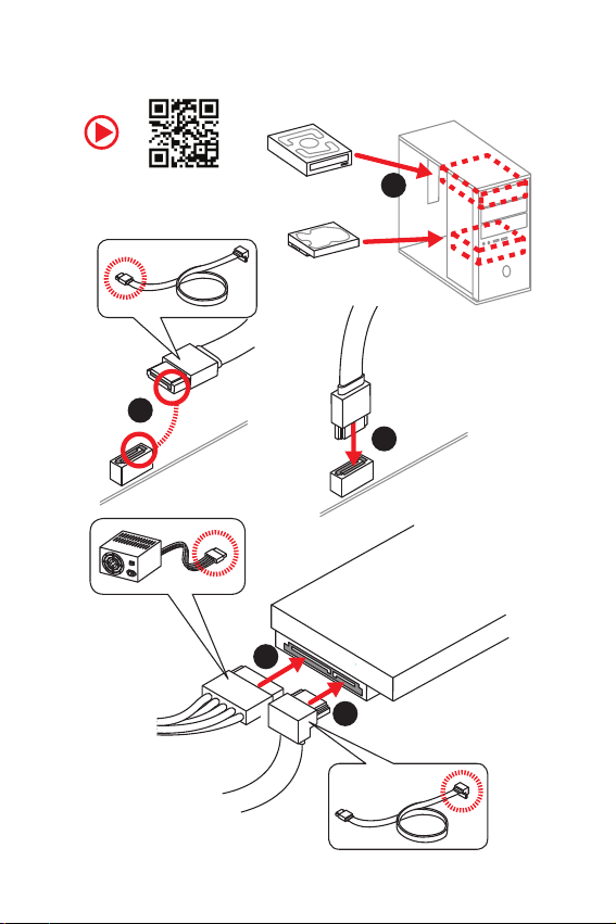
Installing SATA Drives
http://youtu.be/RZsMpqxythc
2
1
3
5
4
6
Quick Start
Page 7
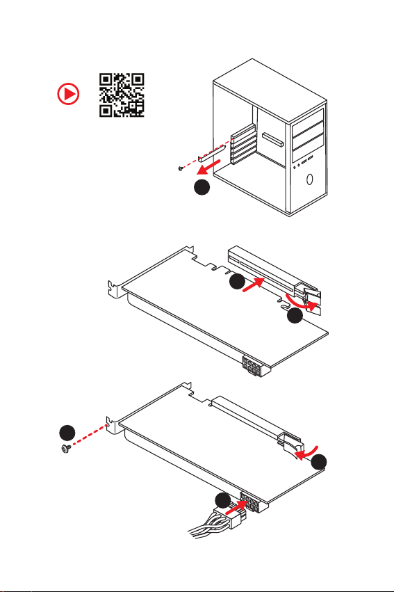
Installing a Graphics Card
http://youtu.be/mG0GZpr9w_A
5
1
3
2
4
6
Quick Start
7
Page 8
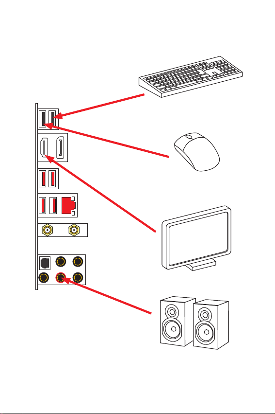
Connecting Peripheral Devices
8
Quick Start
Page 9
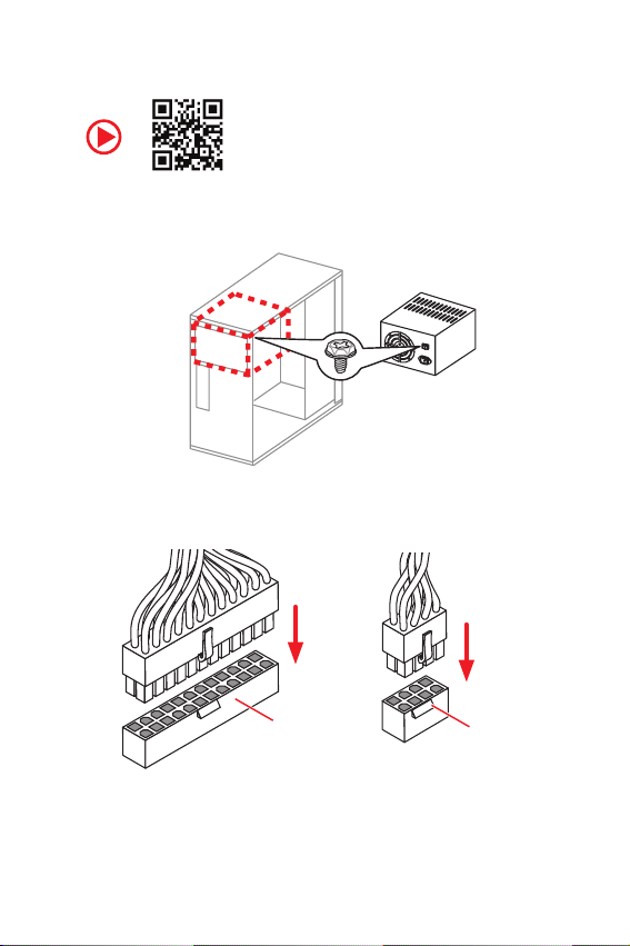
Connecting the Power Connectors
http://youtu.be/gkDYyR_83I4
ATX_PWR1
CPU_PWR1
Quick Start
9
Page 10

Power On
1
2
3
4
10
Quick Start
Page 11

Contents
Quick Start ............................................................................................................. 1
Preparing Tools and Components .......................................................................... 1
Installing a Processor ............................................................................................. 2
Installing DDR4 memory ........................................................................................3
Connecting the Front Panel Header ....................................................................... 4
Installing the Motherboard ..................................................................................... 5
Installing SATA Drives............................................................................................. 6
Installing a Graphics Card ...................................................................................... 7
Connecting Peripheral Devices .............................................................................. 8
Connecting the Power Connectors ......................................................................... 9
Power On............................................................................................................... 10
Specifications ....................................................................................................... 13
Package contents ................................................................................................ 18
Block Diagram .................................................................................................... 19
Rear I/O Panel ..................................................................................................... 20
LAN Port LED Status Table................................................................................... 20
Audio Ports Configuration .................................................................................... 20
Realtek Audio Console ......................................................................................... 21
Overview of Components .................................................................................... 24
CPU Socket ...........................................................................................................26
DIMM Slots ............................................................................................................ 27
PCI_E1: PCIe Expansion Slot ................................................................................ 28
SATA1~4: SATA 6Gb/s Connectors ....................................................................... 28
M2_1~2: M.2 Slots (Key M) ................................................................................... 29
JFP1, JFP2: Front Panel Connectors ................................................................... 30
JTPM1: TPM Module Connector ........................................................................... 30
CPU_PWR1, ATX_PWR1: Power Connectors ....................................................... 31
JUSB1: USB 2.0 Connector .................................................................................. 32
JUSB2: USB 3.1 Gen1 Connector .........................................................................32
CPU_FAN1, PUMP_FAN1, SYS_FAN1: Fan Connectors ....................................... 33
JAUD1: Front Audio Connector ............................................................................ 34
JCI1: Chassis Intrusion Connector ....................................................................... 34
JBAT1: Clear CMOS (Reset BIOS) Jumper ........................................................... 35
EZ Debug LED ....................................................................................................... 35
JRGB1: RGB LED connector ................................................................................. 36
Installing OS, Drivers & Utilities ......................................................................... 37
Installing Windows® 10 ......................................................................................... 37
Contents
11
Page 12

Installing Drivers ..................................................................................................37
Installing Utilities ................................................................................................. 37
MYSTIC LIGHT ...................................................................................................... 38
Device LED effect control screen ......................................................................... 38
BIOS Setup ........................................................................................................... 41
Entering BIOS Setup ............................................................................................. 41
Resetting BIOS ...................................................................................................... 42
Updating BIOS ....................................................................................................... 42
EZ Mode ................................................................................................................ 43
Advanced Mode .................................................................................................... 45
SETTINGS .............................................................................................................. 46
Advanced ............................................................................................................... 46
Boot ....................................................................................................................... 52
Security ................................................................................................................. 53
Save & Exit ............................................................................................................ 54
OC .......................................................................................................................... 55
M-FLASH .............................................................................................................. 61
OC PROFILE .......................................................................................................... 62
HARDWARE MONITOR .......................................................................................... 63
RAID Configuration .............................................................................................. 64
Enabling Intel® Rapid Storage Technology...........................................................64
Creating RAID Volume ......................................................................................... 65
Removing a RAID Volume .................................................................................... 66
Resetting Disks to Non-RAID ...............................................................................67
Rebuilding RAID Array .......................................................................................... 68
Installing RAID Driver ........................................................................................... 69
Installing Intel
®
Rapid Storage Technology Software .......................................... 69
Intel® Optane™ Memory Configuration .............................................................. 70
System Requirements .........................................................................................70
Installing the Intel
Removing the Intel
®
Optane™ memory ................................................................ 70
®
Optane™ memory ............................................................... 72
Troubleshooting .................................................................................................. 73
Regulatory Notices .............................................................................................. 74
Contents
12
Page 13

Specifications
Supports 9th/ 8th Gen Intel
®
Celeron
CPU
Chipset Intel® Z390 Chipset
Memory
Expansion Slot y 1x PCIe 3.0 x16 slot
Onboard Graphics
Storage
RAID
LAN y 1x Realtek
processors for LGA 1151 socket
* Please go to www.intel.com for more compatibility information.
2x DDR4 memory slots, support up to 32GB*
y
y Supports DDR4 4600(OC)/ 4533(OC)/ 4500(OC)/ 4400(OC)/
4300(OC)/ 4266(OC)/ 4200(OC)/ 4133(OC)/ 4000(OC)/
3866(OC)/ 3733(OC)/ 3600(OC)/ 3466(OC)/ 3400(OC)/
3333(OC)/ 3300(OC)/ 3200(OC)/ 3000(OC) /2800(OC)/ 2666/
2400/ 2133 MHz*
y Supports Dual-Channel mode
y Supports non-ECC, un-buffered memory
y Supports Intel
* Please refer www.msi.com for more information on compatible memory.
1x DisplayPort, supports a maximum resolution of
y
4096x2304@60Hz
y 1x HDMI™ port, supports a maximum resolution of
4096x2160@24Hz
®
Intel
Z390 Chipset
y 4x SATA 6Gb/s ports*
y 2x M.2 slots (Key M)
M2_1 supports up to PCIe 3.0 x4 and SATA 6Gb/s, 2260/
2280 storage devices*
M2_2 supports up to PCIe 3.0 x4, 2260/ 2280 storage
devices
®
Intel
Optane™ Memory Ready**
* The SATA2 will be unavailable when installing M.2 SATA device into M2_1 slot.
** Before using Intel
updated the drivers and BIOS to the latest version from MSI website.
Intel® Z390 Chipset
y Supports RAID 0, RAID 1, RAID 5 and RAID 10 for SATA
storage devices
y Supports RAID 0, RAID 1 for M.2 PCIe storage devices
®
8111H Gigabit LAN controller
Continued on next page
®
Core™ / Pentium® Gold /
®
Extreme Memory Profile (XMP)
®
Optane™ memory modules, please ensure that you have
Specifications
13
Page 14

Wireless LAN &
®
Bluetooth
USB
Audio
Back Panel
Connectors
Continued from previous page
Intel® Wireless-AC 9462 card
y Supports 802.11 a/b/g/n/ac, MU-MIMO Rx, 2.4GHz/ 5GHz
up to 344 Mbps
y Supports Bluetooth
®
Z390 Chipset
Intel
y
2x USB 3.1 Gen2 (SuperSpeed USB 10Gbps) Type-A
ports on the back panel
4x USB 3.1 Gen1 (SuperSpeed USB) ports (2 Type-A
ports on the back panel, 2 ports available through the
internal USB 3.1 connector)
4x USB 2.0 (High-speed USB) ports (2 Type-A ports on
the back panel, 2 ports available through the internal
USB 2.0 connector)
®
Realtek
y
®
ALC892 Codec
2.1, 2.1+EDR, 3.0, 4.0, 5
7.1-Channel High Definition Audio
Supports S/PDIF output
2x USB 2.0 Type-A ports
y
y 1x DisplayPort
y 1x HDMI port
y 2x USB 3.1 Gen1 Type-A ports
y 1x LAN (RJ45) port
y 2x USB 3.1 Gen2 Type-A ports
y 5x audio jacks
y 1x Optical S/PDIF OUT connector
Continued on next page
14
Specifications
Page 15

Continued from previous page
1x 24-pin ATX main power connector
y
y 1x 8-pin ATX 12V power connector
y 4x SATA 6Gb/s connectors
y 2x M.2 slots
y 1x USB 3.1 Gen1 connector (supports additional 2 USB 3.1
Gen1 ports)
y 1x USB 2.0 connector (supports additional 2 USB 2.0 ports)
Internal Connectors
I/O Controller NUVOTON NCT6797 Controller Chip
Hardware Monitor
Form Factor
BIOS Features
y 1x 4-pin CPU fan connector
y 1x 4-pin Water Pump connector
y 1x 4-pin system fan connector
y 1x Front panel audio connector
y 2x System panel connectors
y 1x Chassis Intrusion connector
y 1x 4-pin RGB LED connector
y 1x Clear CMOS jumper
y 1x TPM module connector
y
CPU/System temperature detection
y CPU/System fan speed detection
y CPU/System fan speed control
y
Mini-ITX Form Factor
y 6.7 in. x 6.7 in. (17.0 cm x 17.0 cm)
1x 128 Mb flash
y
y UEFI AMI BIOS
y ACPI 6.1, SMBIOS 2.8
y Multi-language
Continued on next page
Specifications
15
Page 16
Software
Dragon Center
Features
Continued from previous page
Drivers
y
y DRAGON CENTER
y
MYSTIC LIGHT
y Open Broadcaster Software (OBS)
y CPU-Z MSI GAMING
y MSI App Player (BlueStacks)
®
y Intel
Extreme Tuning Utility
y Google Chrome™ ,Google Toolbar, Google Drive
y Norton™ Internet Security Solution
GAME OPTIMIZATION
y
y OC Performance
y Hardware Monitor
y Eyerest
y Live Update
Please refer to http://download.msi.
com/manual/mb/DRAGONCENTER2.
pdf for more details.
Continued on next page
16
Specifications
Page 17

Special Features
Continued from previous page
Audio
y
Audio Boost
y Network
Intel Wi-Fi AC
y Storage
Twin Turbo M.2
y Fan
GAMING Fan Control
y LED
Mystic Light Extension(RGB)
Mystic Light SYNC
EZ DEBUG LED
y Protection
PCI-E Steel Armor
y Performance
DDR4 Boost
GAME Boost
INTEL Turbo USB 3.1 Gen 2
CORE Boost
y VR
VR Ready
y Gamer Experience
GAMING HOTKEY
GAMING MOUSE Control
APP Player
y BIOS
Click BIOS 5
Specifications
17
Page 18
Package contents
Please check the contents of your motherboard package. It should contain:
Motherboard MPG Z390I GAMING EDGE AC
Cable
Accessories
Application DVD Driver DVD 1
Documentation
Important
If any of the above items are damaged or missing, please contact your retailer.
SATA 6Gb/s Cables 2
RGB LED Extension 80cm 1
Antenna Set 1
M.2 Screw 2
I/O Shield 1
Case Badge 1
VIP Card 1
User Manual 1
Quick Installation Guide 1
Package contents
18
Page 19
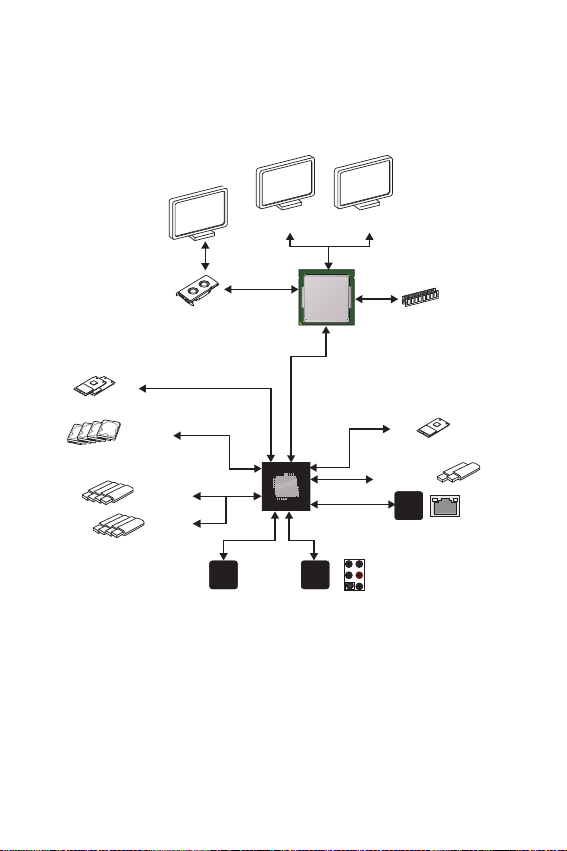
Block Diagram
2x M.2
4x SATA 6Gb/s
4x USB 3.1 Gen1
4x USB 2.0
NV6797
Super I/O
PCIe Bus
PCIE Bus
HDMI
DMI 3.0
PCH
(Rear + Front)
Audio Jacks
Realtek
ALC892
Processor
DisplayPort
2 Channel DDR4 Memory
1x M.2
(E Key for Intel CNVi module only)
2x USB 3.1 Gen2
Realtek
8111H
Block Diagram
19
Page 20
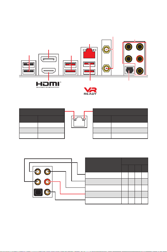
Rear I/O Panel
DisplayPort
USB 2.0
USB 3.1 Gen1
LAN
WiFi Antenna
connectors
Audio Ports
LAN Port LED Status Table
Link/ Activity LED
Status Description
Off No link
Yellow Linked
Blinking Data activity
Audio Ports Configuration
Rear I/O Panel
20
USB 3.1 Gen2
Optical S/PDIF-Out
Speed LED
Status Description
Off 10 Mbps connection
Green 100 Mbps connection
Orange 1 Gbps connection
Audio Ports
Center/ Subwoofer Out ӪӪ
Rear Speaker Out ӪӪӪ
Line-In/ Side Speaker Out Ӫ
Line-Out/ Front Speaker Out ӪӪӪӪ
Mic In
Channel
2468
(Ӫ: connected, Blank: empty)
Page 21
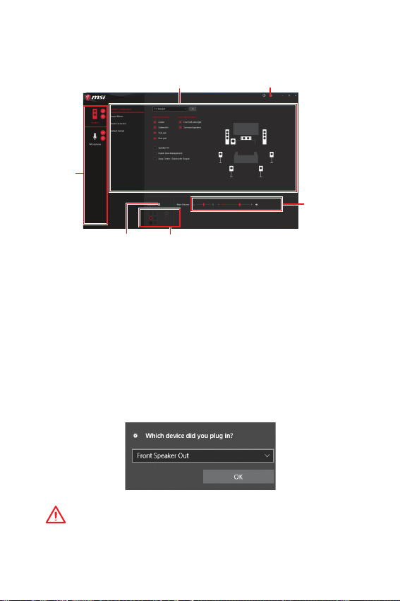
Realtek Audio Console
After Realtek Audio Console is installed. You can use it to change sound settings to get
better sound experience.
Device
Selection
Application Enhancement Advanced Settings
Main Volume
Connector Settings
y Device Selection - allows you to select a audio output source to change the related
options. The check sign indicates the devices as default.
y Application Enhancement - the array of options will provide you a complete guidance
of anticipated sound effect for both output and input device.
y Main Volume - controls the volume or balance the right/left side of the speakers that
you plugged in front or rear panel by adjust the bar.
y Advanced Settings - provides the mechanism to deal with 2 independent audio
streams.
y Jack Status - depicts all render and capture devices currently connected with your
computer.
Jack Status
y Connector Settings - configures the connection settings.
Auto popup di alog
When you plug into a device at an audio jack, a dialogue window will pop up asking you
which device is current connected.
Each jack corresponds to its default setting as shown on the next page.
Important
The pictures above for reference only and may vary from the product you purchased.
Rear I/O Panel
21
Page 22
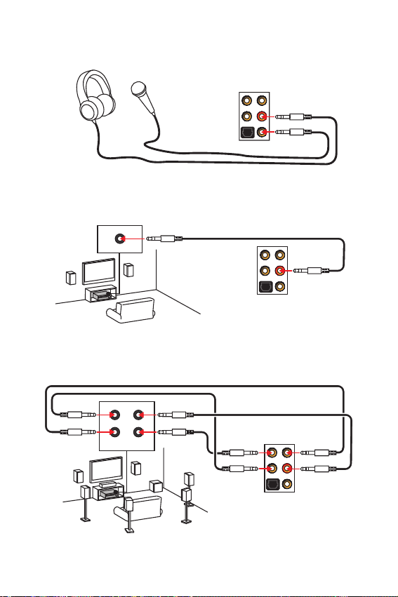
Audio jacks to headphone and microphone diagram
Audio jack s to stereo speakers dia gram
AUDIO INPUT
Audio jack s to 7.1-chann el speakers diagram
AUDIO INPUT
Rear Front
Side Center/
Subwoofer
22
Rear I/O Panel
Page 23

Installing antennas
1. Screw the antennas tight to the antenna connectors as shown below.
2. Orient the antennas.
1
2
Rear I/O Panel
23
Page 24
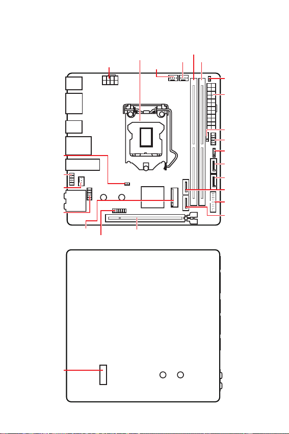
Overview of Components
Front V iew
JBAT1
JUSB1
SYS_FAN1
JAUD1
Rear View
M2_1
CPU_PWR1
JTPM1
CPU Socket
CPU_FAN1
PCI_E1
PUMP_FAN1
DIMMA1
DIMMB1
JCI1
ATX_PWR1
JFP2
JFP1
JRGB1
SATA1
SATA2
SATA3
JUSB2
SATA4
M2_2
Overview of Components
24
Page 25

Component Contents
Port Name Port Type Page
CPU_FAN1, PUMP_FAN1, SYS_FAN1 Fan Connectors
CPU_PWR1, ATX_PWR1 Power Connectors
CPU Socket
DIMMA1/B1
JAUD1 Front Audio Connector
JBAT1 Clear CMOS Jumper
JCI1 Chassis Intrusion Connector
JFP1, JFP2 Front Panel Connectors
JRGB1 RGB LED connector
JTPM1 TPM Module Connector
JUSB1 USB 2.0 Connector
JUSB2 USB 3.1 Gen1 Connector
M2_1~2 M.2 Slots (Key M)
PCI_E1 PCIe Expansion Slot
SATA1~4 SATA 6Gb/s Connectors
LGA1151 CPU Socket 26
DIMM Slots
33
31
27
34
35
34
30
36
30
32
32
29
28
28
Overview of Components
25
Page 26

CPU Socket
Distance from the center of the
CPU to the nearest DIMM slot.
50.13 mm
Introduc tion to the LGA 1151 CPU
The surface of the LGA 1151 CPU has
two notches and a golden triangle to
assist in correctly lining up the CPU for
motherboard placement. The golden
triangle is the Pin 1 indicator.
Important
y
Always unplug the power cord from the power outlet before installing or removing
the CPU.
y
Please retain the CPU protective cap after installing the processor. MSI will deal with
Return Merchandise Authorization (RMA) requests if only the motherboard comes with
the protective cap on the CPU socket.
y
When installing a CPU, always remember to install a CPU heatsink. A CPU heatsink
is necessary to prevent overheating and maintain system stability.
y
Confirm that the CPU heatsink has formed a tight seal with the CPU before booting
your system.
y
Overheating can seriously damage the CPU and motherboard. Always make sure
the cooling fans work properly to protect the CPU from overheating. Be sure to apply
an even layer of thermal paste (or thermal tape) between the CPU and the heatsink to
enhance heat dissipation.
y
Whenever the CPU is not installed, always protect the CPU socket pins by covering
the socket with the plastic cap.
y
If you purchased a separate CPU and heatsink/ cooler, Please refer to the
documentation in the heatsink/ cooler package for more details about installation.
y
This motherboard is designed to support overclocking. Before attempting to
overclock, please make sure that all other system components can tolerate
overclocking. Any attempt to operate beyond product specifications is not
recommended. MSI
operation beyond product specifications.
®
does not guarantee the damages or risks caused by inadequate
Overview of Components
26
Page 27

DIMM Slots
DIMMA1 DIMMB1
Channel A Channel B
Important
y
Always insert memory modules in the DIMMB1 slot first.
y
Due to chipset resource usage, the available capacity of memory will be a little less
than the amount of installed.
y
Based on CPU specification, the Memory DIMM voltage below 1.35V is suggested to
protect the CPU.
y
Please note that the maximum capacity of addressable memory is 4GB or less
for 32-bit Windows OS due to the memory address limitation. Therefore, we
recommended that you to install 64-bit Windows OS if you want to install more than
4GB memory on the motherboard.
y
Some memory may operate at a lower frequency than the marked value when
overclocking due to the memory frequency operates dependent on its Serial Presence
Detect (SPD). Go to BIOS and find the Memory Try It! to set the memory frequency if
you want to operate the memory at the marked or at a higher frequency.
y
It is recommended to use a more efficient memory cooling system for full DIMMs
installation or overclocking.
y
The stability and compatibility of installed memory module depend on installed CPU
and devices when overclocking.
Overview of Components
27
Page 28

PCI_E1: PCIe Expansion Slot
Important
y
If you install a large and heavy graphics card, you need to use a tool such as MSI
Gaming Series Graphics Card Bolster to support its weight and to prevent deformation
of the slot.
y
When adding or removing expansion cards, always turn off the power supply and
unplug the power supply power cable from the power outlet. Read the expansion
cards documentation to check for any necessary additional hardware or software
changes.
SATA1~4: SATA 6Gb/s Connectors
These connectors are SATA 6Gb/s interface ports. Each connector can connect to one
SATA device.
SATA 1
SATA 2
SATA 3
SATA 4
Important
y
Please do not fold the SATA cable at a 90-degree angle. Data loss may result during
transmission otherwise.
y
SATA cables have identical plugs on either sides of the cable. However, it is
recommended that the flat connector be connected to the motherboard for space
saving purposes.
Overview of Components
28
Page 29

M2_1~2: M.2 Slots (Key M)
Important
y
Intel® RST only supports PCIe M.2 SSD with UEFI ROM.
y
Intel® Optane™ Memory Ready.
M2_1
M2_2
Installing M.2 device
1. Loosen the M.2 riser screw from the
motherboard.
2. Move and fasten the M.2 riser screw to
the appropriate location for your M.2
SSD.
3. Insert your M.2 SSD into the M.2 slot at a
30-degree angle.
Video Dem onstration
Watch the video to learn how to Install
M.2 module.
http://youtu.be/JCTFABytrYA
4. Secure the M.2 SSD in place with
the supplied M.2 screw.
3
2
30o
4
Supplied M.2 screw
1
Overview of Components
29
Page 30

JFP1, JFP2: Front Panel Connectors
These connectors connect to the switches and LEDs on the front panel.
10 9
Reserved
+
-
+-
-+
12
JFP1
Reset Switch
+
HDD LED
Buzzer
+
1
JFP2
+
-
Power Switch
Power LED
1 HDD LED + 2 Power LED +
3 HDD LED - 4 Power LED -
5 Reset Switch 6 Power Switch
7 Reset Switch 8 Power Switch
9 Reserved 10 No Pin
Speaker
1 Speaker - 2 Buzzer +
3 Buzzer - 4 Speaker +
JTPM1: TPM Module Connector
This connector is for TPM (Trusted Platform Module). Please refer to the TPM security
platform manual for more details and usages.
214
1
13
1 LPC Clock 2 3V Standby power
3 LPC Reset 4 3.3V Power
5 LPC address & data pin0 6 Serial IRQ
7 LPC address & data pin1 8 5V Power
9 LPC address & data pin2 10 No Pin
11 LPC address & data pin3 12 Ground
13 LPC Frame 14 Ground
Overview of Components
30
Page 31

CPU_PWR1, ATX_PWR1: Power Connectors
These connectors allow you to connect an ATX power supply.
5
8
41
1 Ground 5 +12V
2 Ground 6 +12V
3 Ground 7 +12V
4 Ground 8 +12V
1 +3.3V 13 +3.3V
2 +3.3V 14 -12V
24
12
ATX_PWR1
131
3 Ground 15 Ground
4 +5V 16 PS-ON#
5 Ground 17 Ground
6 +5V 18 Ground
7 Ground 19 Ground
8 PWR OK 20 Res
9 5VSB 21 +5V
10 +12V 22 +5V
11 +12V 23 +5V
12 +3.3V 24 Ground
Important
Make sure that all the power cables are securely connected to a proper ATX power
supply to ensure stable operation of the motherboard.
CPU_PWR1
Overview of Components
31
Page 32

JUSB1: USB 2.0 Connector
This connector allows you to connect USB 2.0 ports on the front panel.
12
109
1 VCC 2 VCC
3 USB0- 4 USB1-
5 USB0+ 6 USB1+
7 Ground 8 Ground
9 No Pin 10 NC
Important
y
Note that the VCC and Ground pins must be connected correctly to avoid possible
damage.
y
In order to recharge your iPad,iPhone and iPod through USB ports, please install MSI
Dragon Center utility.
JUSB2: USB 3.1 Gen1 Connector
This connector allows you to connect USB 3.1 Gen1 ports on the front panel.
10 11
1
20
1 Power 11 USB2.0+
2 USB3_RX_DN 12 USB2.0-
3 USB3_RX_DP 13 Ground
4 Ground 14 USB3_TX_C_DP
5 USB3_TX_C_DN 15 USB3_TX_C_DN
6 USB3_TX_C_DP 16 Ground
7 Ground 17 USB3_RX_DP
8 USB2.0- 18 USB3_RX_DN
9 USB2.0+ 19 Power
10 NC 20 No Pin
Important
Note that the Power and Ground pins must be connected correctly to avoid possible
damage.
Overview of Components
32
Page 33

CPU_FAN1, PUMP_FAN1, SYS_FAN1: Fan Connectors
Fan connectors can be classified as PWM (Pulse Width Modulation) Mode or DC Mode.
PWM Mode fan connectors provide constant 12V output and adjust fan speed with
speed control signal. DC Mode fan connectors control fan speed by changing voltage.
You can follow the instruction below to adjust the fan connector to PWM or DC Mode.
1
CPU_FAN1
(Default : Auto-detection
Mode)
(Default : DC Mode)
SYS_FAN1
1
PUMP_FAN1
(Default : PWM Mode)
1
Switching f an mode and adjustin g fan speed
You can switch between PWM mode and DC mode and adjust fan speed in BIOS >
HARDWARE MONITOR.
Select PWM mode or DC mode
There are gradient points of the fan speed that allow you to adjust
fan speed in relation to CPU temperature.
Important
Make sure fans are working properly after switching the PWM/ DC mode.
Pin definition of fan connectors
PWM Mode pin definition
1 Ground 2 +12V
3 Sense 4 Speed Control Signal
DC Mode pin definition
1 Ground 2 Voltage Control
3 Sense 4 NC
Overview of Components
33
Page 34

JAUD1: Front Audio Connector
This connector allows you to connect audio jacks on the front panel.
12
109
1 MIC L 2 Ground
3 MIC R 4 NC
5 Head Phone R 6 MIC Detection
7 SENSE_SEND 8 No Pin
9 Head Phone L 10 Head Phone Detection
JCI1: Chassis Intrusion Connector
This connector allows you to connect the chassis intrusion switch cable.
Normal
(default)
Trigger the chassis
intrusion event
Using chas sis intrusion dete ctor
1. Connect the JCI1 connector to the chassis intrusion switch/ sensor on the chassis.
2. Close the chassis cover.
3. Go to BIOS > SETTINGS > Security > Chassis Intrusion Configuration.
4. Set Chassis Intrusion to Enabled.
5. Press F10 to save and exit and then press the Enter key to select Yes.
6. Once the chassis cover is opened again, a warning message will be displayed on
screen when the computer is turned on.
Resetti ng the chassis intr usion warning
1. Go to BIOS > SETTINGS > Security > Chassis Intrusion Configuration.
2. Set Chassis Intrusion to Reset.
3. Press F10 to save and exit and then press the Enter key to select Yes.
Overview of Components
34
Page 35

JBAT1: Clear CMOS (Reset BIOS) Jumper
There is CMOS memory onboard that is external powered from a battery located on
the motherboard to save system configuration data. If you want to clear the system
configuration, set the jumpers to clear the CMOS memory.
Keep Data
(default)
Resetti ng BIOS to default value s
1. Power off the computer and unplug the power cord.
2. Use a jumper cap to short JBAT1 for about 5-10 seconds.
3. Remove the jumper cap from JBAT1.
4. Plug the power cord and Power on the computer.
EZ Debug LED
These LEDs indicate the debug status of the motherboard.
CPU - indicates CPU is not detected or fail.
DRAM - indicates DRAM is not detected or fail.
VGA - indicates GPU is not detected or fail.
BOOT - indicates the booting device is not detected
or fail.
Clear CMOS/
Reset BIOS
Overview of Components
35
Page 36

JRGB1: RGB LED connector
This connector allows you to connect the 5050 RGB LED strips 12V.
1
1 +12V 2
3R4
G
B
1
JRGB1
Extension cable
5050 RGB LED strips 12V
Important
y
The JRGB1 connectors support 5050 RGB LED strip (12V/G/R/B) with the maximum
power rating of 3A (12V).
y
Please keeping the LED strip shorter than 2 meters to prevent dimming.
y
Always turn off the power supply and unplug the power cord from the power outlet
before installing or removing the LED strip.
y
Please use MSIs software to control the extended LED strip.
Overview of Components
36
Page 37

Installing OS, Drivers & Utilities
Please download and update the latest utilities and drivers at www.msi.com
Installing Windows® 10
1.
Power on the computer.
2.
Insert the Windows
3.
Press the Restart button on the computer case.
4.
Press F11 key during the computer POST (Power-On Self Test) to get into Boot
Menu.
5.
Select the Windows
6.
Press any key when screen shows Press any key to boot from CD or DVD...
message.
7.
Follow the instructions on the screen to install Windows
Installing Drivers
1.
Start up your computer in Windows® 10.
2.
Insert MSI
3.
Click the Select to choose what happens with this disc pop-up notification, then
select Run DVDSetup.exe to open the installer. If you turn off the AutoPlay feature
from the Windows Control Panel, you can still manually execute the DVDSetup.exe
from the root path of the MSI Driver Disc.
4.
The installer will find and list all necessary drivers in the Drivers/Software tab.
5.
Click the Install button in the lower-right corner of the window.
6.
The drivers installation will then be in progress, after it has finished it will prompt
you to restart.
7.
Click OK button to finish.
8.
Restart your computer.
Installing Utilities
Before you install utilities, you must complete drivers installation.
1.
Open the installer as described above.
2.
Click the Utilities tab.
3.
Select the utilities you want to install.
4.
Click the Install button in the lower-right corner of the window.
5.
The utilities installation will then be in progress, after it has finished it will prompt
you to restart.
6.
Click OK button to finish.
7.
Restart your computer.
®
10 installation disc/USB into your computer.
®
10 installation disc/USB from the Boot Menu.
®
Driver Disc into your optical drive.
®
10.
Installing OS, Drivers & Utilities
37
Page 38

MYSTIC LIGHT
MYSTIC LIGHT is an application that allows you to control LED light effects of MSI &
partner products. For some earlier products, you can go to product download page to
download the applicable LED control software.
Device LED effect control screen
When you start up MYSTIC LIGHT, there will be a list of auto-detected devices on
the top of the screen. You can click the device icon to switch control screen between
devices from the list and you can synchronize their LED effects.
To change LED effect, select the device and LED area you wish, and then select a LED
effect from on the left column.
Device
synchronization
LED area
LED effect
selector
LED color
selector
y Light effect selector - allow you to select LED light effects. Please note that for light
effect, the option would be more or less depending on the devices you have, it will only
list the light effects which are available for all included devices. Each page of effect
selector lists six effects, you can use the page navigation on the bottom to find more
options.
y LED Color selector - In this section, you may select the color for single light effects
(Stack, Breathing, Flashing etc.).
There are four custom color slots on the outer arc and six unchangeable
default colors on the inner arc. You can simply change LED color by
clicking a color on the outer or inner arc. To change the custom colors,
click one of the color slots on the outer arc to store the color of your
choice.
Then use the Hue Circle to choose the color you want. The color you
choose will be displayed on the center circle. Drag the brightness
slider up to increase brightness or drag down to decrease brightness.
selector
Effect speed
level
Brightness
level
Apply button
MYSTIC LIGHT User Guide
38
You can specify a color by editing an RGB (red, green, blue) value
between 0 and 255.
Page 39

y LED area selector - allows you to select the LED area on the device. The LED effects
vary depending on your LED area selection.
y Effect speed level - allows you to adjust the LED light effect switching speed. Please
note that this function will only be available if your device supports it.
Select more dots to increase the rate of change of
the effect and fewer dots to decrease the speed.
Slow
y Brightness level - allows you to adjust LED light brightness. Please note that this
function will only be available if your device supports it.
Darkness
y Apply Button - Each time you change the
configurations, you need to click the Apply
button to apply changes.
y Device synchronization - In this section, you may synchronize LED light effect to your
devices.
To synchronize devices - click the chain icon under device icon, when the broken-
chain icon changes to the red-chain icon, the device has synchronized the LED
effect settings with the other devices.
Fast
Select more dots to increase the
Brightness
LED brightness and fewer dots to
decrease the LED brightness.
Red-chain icon - indicates the
device has been synchronized.
Individual - You can also change settings for single device. To do that, click the
chain icon and turn the color to gray as below.
Device icon - click it to enter the device LED effect setting
screen. When it is turn red, it indicates the device youre
currently setting.
Broken-chain icon - indicates the
device is not synchronized.
MYSTIC LIGHT User Guide
39
Page 40

Synchronize all - There is a quick button on the upper right that allows you to
synchronize all your devices with one click. Click the All Sync button, then the chain
icons under all sync devices will be changed in red-chain icons and the Profile
control panel will appear on the left.
All Sync
button
Profiles
control
panel
Profile control panel - used to save All Sync profile settings.
Profile name -
allows you to edit
the Profile name.
MYSTIC LIGHT User Guide
40
Create button - create a
new Profile setting.
Delete button - delete the
Profile setting.
Apply button - apply the
Profile setting.
Save button - saves sync device
settings and lighting effect settings to
the current Sync Profile.
Page 41

BIOS Setup
The default settings offer the optimal performance for system stability in normal
conditions. You should always keep the default settings to avoid possible system
damage or failure booting unless you are familiar with BIOS.
Important
y
BIOS items are continuously update for better system performance. Therefore, the
description may be slightly different from the latest BIOS and should be for reference
only. You could also refer to the HELP information panel for BIOS item description.
y
The pictures in this chapter are for reference only and may vary from the product you
purchased.
Entering BIOS Setup
Please refer the following methods to enter BIOS setup.
y Press Delete key, when the Press DEL key to enter Setup Menu, F11 to enter Boot
Menu message appears on the screen during the boot process.
y In MSI Dragon Center application, click on GO2BIOS button and choose OK. The
system will reboot and enter BIOS setup directly.
Functi on key
F1: General Help
F2: Add/ Remove a favorite item
F3: Enter Favorites menu
F4: Enter CPU Specifications menu
F5: Enter Memory-Z menu
F6: Load optimized defaults
F7: Switch between Advanced mode and EZ mode
F8: Load Overclocking Profile
F9: Save Overclocking Profile
F10: Save Change and Reset*
F12: Take a screenshot and save it to USB flash drive (FAT/ FAT32 format only).
Ctrl+F: Enter Search page
* When you press F10, a confirmation window appears and it provides the modification
information. Select between Yes or No to confirm your choice.
BIOS Setup
41
Page 42

Resetting BIOS
You might need to restore the default BIOS setting to solve certain problems. There are
several ways to reset BIOS:
y Go to BIOS and press F6 to load optimized defaults.
y Short the Clear CMOS jumper on the motherboard.
Important
Be sure the computer is off before clearing CMOS data. Please refer to the Clear
CMOS jumper section for resetting BIOS.
Updating BIOS
Updating B IOS with M-FLA SH
Before updating:
Please download the latest BIOS file that matches your motherboard model from MSI
website. And then save the BIOS file into the USB flash drive.
Updating BIOS:
1. Insert the USB flash drive that contains the update file into the USB port.
2. Please refer the following methods to enter flash mode.
Reboot and press Ctrl + F5 key during POST and click on Yes to reboot the
system.
Reboot and press Del key during POST to enter BIOS. Click the M-FLASH button
and click on Yes to reboot the system.
3. Select a BIOS file to perform the BIOS update process.
4. After the flashing process is 100% completed, the system will reboot
automatically.
Updating t he BIOS with MSI DRAG ON CENTER
Before updating:
Make sure the LAN driver is already installed and the Internet connection is set
properly.
Updating BIOS:
1. Install and launch MSI DRAGON CENTER.
2. Select BIOS Update.
3. Click on Scan button.
4. Click on Download icon to download and install the latest BIOS file.
5. Click Next and choose In Windows mode. And then click Next and Start to start
updating BIOS.
6. After the flashing process is 100% completed, the system will restart
automatically.
42
BIOS Setup
Page 43

EZ Mode
At EZ mode, it provides the basic system information and allows you to configure the
basic setting. To configure the advanced BIOS settings, please enter the Advanced
Mode by pressing the Setup Mode switch or F7 function key.
GAME BOOST
switch
Information
display
M-Flash
Favorites
Hardware
Monitor
y GAME BOOST switch - click on it to toggle the GAME BOOST for OC.
y XMP switch - click on the inner circle to enable/ disable the X.M.P. (Extreme Memory
Profile). Switch the outer circle to select the X.M.P. profile. This switch will only be
available if the X.M.P. supported memory module is installed.
y Setup Mode switch - press this tab or the F7 key to switch between Advanced mode
and EZ mode.
y Screenshot - click on this tab or the F12 key to take a screenshot and save it to USB
flash drive (FAT/ FAT32 format only).
y Search - click on this tab or the Ctrl+F keys and the search page will show. It allows
you to search BIOS item by key word. Move the mouse over a blank space and right
click the mouse to exit search page.
In search page, only the F6, F10 and F12 function keys are available.
y Language - allows you to select the language of BIOS setup.
y System information - shows the CPU/ DDR speed, CPU/ MB temperature, MB/ CPU
type, memory size, CPU/ DDR voltage, BIOS version and build date.
y Boot device priority bar - you can move the device icons to change the boot priority.
The boot priority from high to low is left to right.
Important
XMP switch
SearchScreenshotSetup Mode switch
Language
System
information
Boot device
priority bar
Function
buttons
BIOS Setup
43
Page 44

y Information display - click on the CPU, Memory, Storage, Fan Info and Help buttons
on left side to display related information.
y Function buttons - enable or disable the LAN Option ROM, M.2/ Optane Genie, HD
audio controller, AHCI/ RAID, CPU Fan Fail Warning Control and BIOS Log Review by
clicking on their respective button.
y M-Flash - click on this button to perform M-Flash function that provides the way to
update BIOS with a USB flash drive.
y Hardware Monitor - click on this button to display the Hardware Monitor menu that
allows you to manually control the fan speed by percentage.
y Favorites menu - press the F3 key to enter Favorites menu. It allows you to create
personal BIOS menu where you can save and access favorite/ frequently-used BIOS
setting items.
Default HomePage - allows you to select a BIOS menu (e.g. SETTINGS, OC...,etc)
as the BIOS home page.
Favorite1~5 page - allows you to add the frequently-used/ favorite BIOS setting
items in one page.
To add a BIOS item to a favorite page (Favorite 1~5)
1. Move the mouse over a BIOS item not only on BIOS menu but also on search
page.
2. Right-click or press F2 key.
3. Choose a favorite page and click on OK.
To delete a BIOS item from favorite page
1. Move the mouse over a BIOS item on favorite page (Favorite 1~5)
2. Right-click or press F2 key.
3. Choose Delete and click on OK.
44
BIOS Setup
Page 45

Advanced Mode
Press Setup Mode switch or F7 function key can switch between EZ Mode and
Advanced Mode in BIOS setup.
XMP switch
GAME BOOST
switch
BIOS menu
selection
Menu display
y GAME BOOST switch/ XMP switch/ Setup Mode switch/ Screenshot/ Language/
Search/ System information/ Boot device priority bar - please refer to the
descriptions of EZ Mode Overview section.
SearchScreenshotSetup Mode switch
Language
System
information
Boot device
priority bar
BIOS menu
selection
y BIOS menu selection - the following options are available:
SETTINGS - allows you to specify the parameters for chipset and boot devices.
OC - allows you to adjust the frequency and voltage. Increasing the frequency may
get better performance.
M-FLASH - provides the way to update BIOS with a USB flash drive.
OC PROFILE - allows you to manage overclocking profiles.
HARDWARE MONITOR - allows you to set the speeds of fans and monitor voltages
of system.
BOARD EXPLORER - provides the information of installed devices on this
motherboard.
y Menu display - provides BIOS setting items and information to be configured.
BIOS Setup
45
Page 46

SETTINGS
System Statu s
f System Date
Sets the system date. Use tab key to switch between date elements.
The format is <day> <month> <date> <year>.
<day> Day of the week, from Sun to Sat, determined by BIOS. Read-only.
<month> The month from Jan. through Dec.
<date> The date from 1 to 31 can be keyed by numeric function keys.
<year> The year can be adjusted by users.
f System Time
Sets the system time. Use tab key to switch between time elements.
The time format is <hour> <minute> <second>.
f SATA PortX/ M2_X
Shows the information of connected SATA/ M.2 devices.
Important
If the connected SATA device is not displayed, turn off computer and re-check SATA
cable and power cable connections of the device and motherboard.
f System Information
Shows detailed system information, including CPU type, BIOS version, and Memory
(read only).
f DMI Information
Shows system information, desktop Board Information and chassis Information. (Read
only).
Advanced
f PCI Subsystem Settings
Sets PCI, PCI express interface protocol and latency timer. Press Enter to enter the
sub-menu.
46
BIOS Setup
Page 47

f PEG X - Max Link Speed [Auto]
Sets PCI Express protocol of PCIe x16 slots for matching different installed devices.
[Auto] This item will be configured automatically by BIOS.
[Gen1] Enables PCIe Gen1 support only.
[Gen2] Enables PCIe Gen2 support only.
[Gen3] Enables PCIe Gen3 support only.
f PCI Latency Timer [32]
Sets latency timer of PCI interface device.
[Options: 32, 64, 96, 128, 160, 192, 224, 248 PCI Bus clocks]
f Above 4G memory/ Crypto Currency mining [Disabled]
Enables or disables 64-bit capable devices to be decoded in above 4G address
space. It is only available if the system supports 64-bit PCI decoding.
[Enabled] Allows you to utilize more than 4x GPUs.
[Disabled] Disables this function.
f ACPI Settings
Sets ACPI parameters of onboard power LED behaviors. Press Enter to enter the sub-
menu.
f Power LED [Blinking]
Sets shining behaviors of the onboard Power LED.
[Dual Color] The power LED turns to another color to indicate the S3 state.
[Blinking] The power LED blinks to indicate the S3 state.
f CPU Over Temperature Alert [Auto]
Enables or disables the CPU overheating alert when CPU temperature is over 80
degrees centigrade.
f Integrated Peripherals
Sets integrated peripherals' parameters, such as LAN, HDD, USB and audio. Press
Enter to enter the sub-menu.
f Onboard LAN Controller [Enabled]
Enables or disables the onboard LAN controller.
f LAN Option ROM [Disabled]
Enables or disables the legacy network Boot Option ROM for detailed settings. This
item will appear when Onboard LAN Controller is enabled.
[Enabled] Enables the onboard LAN Boot ROM.
[Disabled] Disables the onboard LAN Boot ROM.
f Network Stack [Disabled]
Sets UEFI network stack for optimizing IPv4 / IPv6 function.
[Enabled] Enables UEFI network stack.
[Disabled] Disables UEFI network stack.
BIOS Setup
47
Page 48

f Ipv4 PXE Support [Enabled]
When Enabled, the system UEFI network stack will support Ipv4 protocol. This item
will appear when Network Stack is enabled.
[Enabled] Enables the Ipv4 PXE boot support.
[Disabled] Disables the Ipv4 PXE boot support.
f Ipv6 PXE Support [Enabled]
When Enabled, the system UEFI network stack will support Ipv6 protocol. This item
will appear when Network Stack is enabled.
[Enabled] Enables the Ipv6 PXE boot support.
[Disabled] Disables the Ipv6 PXE boot support.
f SATA Mode [AHCI Mode]
Sets the operation mode of the onboard SATA controller.
[AHCI Mode] Specify the AHCI mode for SATA storage devices. AHCI
[RAID/ Optane Mode] Enables RAID function for SATA storage devices or
f M2_X-RST Pcie Storage Remapping [Disabled]
Enables or disables Intel Rapid Storage for M.2 PCIe storage device.
f M.2/Optane Genie [Disabled]
Enables or disables M.2 storage/ Optane memory. M.2 Genie provides a convenient
way for setting up M.2 device. When set to Enabled, it will support Intel Optane
memory when it is installed and support RAID function when 2 or more M.2 devices
are installed.
f SATAx Hot Plug [Disabled]
Allows user to enable or disable the SATA hot plug support.
[Enabled] Enables hot plug support for the SATA ports.
[Disabled] Disables hot plug support for the SATA ports.
f HD Audio Controller [Enabled]
Enables or disables the onboard High Definition Audio controller.
f Integrated Graphics Configuration
Adjusts integrated graphics settings for optimum system. Press Enter to enter the
sub-menu.
f Initiate Graphic Adapter [PEG]
Selects a graphics device as the primary boot device.
[IGD] Integrated Graphics Display.
[PEG] PCI-Express Graphics Device.
f Integrated Graphics Share Memory [64M]
Selects a fixed amount of system memory allocated to the onboard graphics. This
item will appear when IGD Multi-Monitor is enabled.
(Advanced Host Controller Interface) offers some
advanced features to enhance the speed and performance
of SATA storage device, such as Native Command Queuing
(NCQ) and hot-plugging.
enables Optane function for NVMe or PCIe storage devices.
48
BIOS Setup
Page 49

f IGD Multi-Monitor [Disabled]
Enables or disables the multi-screen output from integrated graphics and external
graphics card. This item appears when Initiate Graphic Adapter set to PEG.
[Enabled] Enables multi-screen function for both integrated and external
[Disabled] Disables this function.
f USB Configuration
Sets the onboard USB controller and device function. Press Enter to enter the submenu.
f USB Controller [Enabled]
Enables or disables all USB controller.
f XHCI Hand-off [Diasbled]
Enables or disables XHCI hand-off support for the operating system without XHCI
hand-off feature.
f Legacy USB Support [Enabled]
Sets Legacy USB function support.
[Auto] The system will automatically detect if any USB device is connected
[Enabled] Enable the USB support under legacy mode.
[Disabled] The USB devices will be unavailable under legacy mode.
f Power Management Setup
Sets system Power Management of ErP and AC Power Loss behaviors. Press Enter to
enter the sub-menu.
f ErP Ready [Disabled]
Enables or disables the system power consumption according to ErP regulation.
[Enabled] Optimize the system power consumption according to ErP
[Disabled] Disables this function.
f Restore after AC Power Loss [Power Off]
Sets the system behaviors while encountering the AC power loss.
[Power Off] Leaves the system in power off state after restoring AC power.
[Power On] Boot up the system after restoring AC power.
[Last State] Restores the system to the previous state (power on/ power off)
f System Power Fault Protection [Disabled]
Enables or disables the system to boot up when detecting abnormal voltage input.
[Enabled] Protect the system from unexpected power operation and remain
[Disabled] Disables this function.
graphics cards.
and enable the legacy USB support.
regulation. It will not support S4 & S5 wake up by USB, PCI and PCIe
devices.
before AC power loss.
the shut down status.
BIOS Setup
49
Page 50

f USB Standby Power at S4/S5 [Disabled]
Enables or disables the standby power for all USB ports. This item will be available
when Resume By USB Device is Disabled.
f Windows OS Configuration
Sets Windows OS detailed configuration and behaviors. Press Enter to enter the sub-
menu.
f Windows 10 WHQL Support [Disabled]
Enables the supports for Windows 10 or disables for other operating systems.
Before enabling this item, make sure all installed devices & utilities (hardware &
software) should meet the Windows 10 requirements.
[Enabled] The system will switch to UEFI mode to meet the Windows
[Disabled] Disables this function.
f MSI Fast Boot [Disabled]
MSI Fast Boot is the fastest way to boot the system. It will disable more devices to
speed up system boot time which is faster than the boot time of Fast Boot.
[Enabled] Enables the MSI Fast Boot function to speed up booting time. And
[Disabled] Disables MSI Fast Boot.
equirement.
the following Fast Boot field will be disabled and fixed.
Important
When MSI Fast Boot is enabled, you can use MSI FAST BOOT application to enter BIOS
setup if needed. Please refer Entering BIOS Setup section for details.
f Fast Boot [Enabled]
Enables or disables the fast boot feature for Windows 10. This item will only be
available when MSI Fast Boot is disabled.
[Enabled] Enables the Fast Boot configuration to accelerate system boot time.
[Disabled] Disables the Fast Boot configuration.
f Internal GOP Configuration
Manages the onboard Graphics Output Protocol (GOP). Press Enter to enter
the sub-menu. This sub-menu will appear when Windows 10 WHQL Support is
enabled.
f Secure Boot
Sets the Windows secure boot to prevent the unauthorized accessing. Press Enter
to enter the sub-menu. This sub-menu will appear when Windows 10 WHQL
Support is enabled.
f Secure Boot Support [Disabled]
Enables or disables secure boot support.
[Enabled] Enables the secure boot function and allow you to set the secure
[Disabled] Disables this function.
boot settings.
50
BIOS Setup
Page 51

f Secure Boot Mode [Standard]
Selects the secure boot mode. This item is to select how the secure boot keys be
loaded. This item appears when Secure Boot Support is enabled.
[Standard] The system will automatically load the secure keys from BIOS.
[Custom] Allows user to configure the secure boot settings and manually load
f Key Management
Manages the secure boot keys. Press <Enter> to enter the sub-menu. This submenu will appear when Secure Boot Mode sets to Custom.
f Wake Up Event Setup
Sets system wake up behaviors for different sleep modes. Press Enter to enter the
sub-menu.
f Wake Up Event By [BIOS]
Selects the wake up event by BIOS or operating system.
[BIOS] Activates the following items, set wake up events of these items.
[OS] The wake up events will be defined by OS.
f Resume By RTC Alarm [Disabled]
Disables or enables the system wake up by RTC Alarm.
[Enabled] Enables the system to boot up on a scheduled time/ date.
[Disabled] Disables this function.
f Date (of month) Alarm/ Time (hh:mm:ss) Alarm
Sets RTC alarm date/ Time. If Resume By RTC Alarm is set to [Enabled], the system
will automatically resume (boot up) on a specified date/hour/minute/second in
these fields (using the + and - keys to select the date & time settings).
f Resume By PCI-E Device [Disabled]
Enables or disables the wake up function of installed PCI-E expansion cards,
integrated LAN controllers or USB devices which are supported by third party
integrated chips.
[Enabled] Enables the system to be awakened from the power saving modes
[Disabled] Disables this function.
f Resume By Onboard Intel LAN/CNVI [Disabled]
Enables or disables the system wake up by Onboard Intel LAN.
[Enabled] Enables the system to be awakened from the power saving modes
[Disabled] Disables this function.
f Resume by USB Device [Disabled]
Enables or disables the system wake up by USB devices.
[Enabled] Enables the system to be awakened from sleep state when activity of
[Disabled] Disables this function.
the secure keys.
when activity or input signal of PCIe device is detected.
when activity or input signal of Intel LAN device is detected.
USB device is detected.
BIOS Setup
51
Page 52

f Secure Erase+
Enables or disables Secure Erase+ function. Secure Erase+ is the best way to
effectively wipe all data from a SSD. Please note that data of SSD will be erased after
enabling Secure Erase+.
f Realtek ( R ) Ethernet Connection
Shows driver information and configuration of the ethernet controller parameter. This
item will appear when Network Stack is enabled.
Boot
Sets the sequence of system boot devices.
f Full Screen Logo Display [Enabled]
Enables or disables to show the full screen logo while system POST.
[Enabled] Shows the logo in full screen.
[Disabled] Shows the POST messages.
f GO2BIOS [Disabled]
Allows system to enter BIOS setup directly by pressing the Power button for 4 sec pon
bootup.
[Enabled] The system boots straight to the BIOS setup by long pressing the power
[Disabled] Disables this function.
f Bootup NumLock State [On]
Select the keyboard NumLock state upon bootup.
f Info Block effect [Unlock]
Sets the state of Help information block.
[Unlock] Sliding effect.
[Lock] Fix the Help information block on the screen.
f POST Beep [Disabled]
Enables or disables the beep sound during system POST.
f Boot Mode Select [LEGACY+UEFI]
Sets the system boot mode from legacy or UEFI architecture depending on OS
installation requirement. This item will become un-selectable and will be configured
automatically by BIOS when Windows 10 WHQL Support is enabled.
[UEFI] Enables UEFI BIOS boot mode support only.
[LEGACY+UEFI] Enables both Legacy BIOS boot mode and UEFI BIOS boot
f FIXED BOOT ORDER Priorities
Sets device priority for system boot.
f Boot Option Priorities
These items are used to prioritize the installed boot devices.
button about 4 seconds when the system is off.
mode.
52
BIOS Setup
Page 53

Security
f Administrator Password
Sets administrator password for system security. User has full rights to change the
BIOS items with administrator password. After setting the administrator password, the
state of this item will show Installed.
f User Password
Sets User Password for system security. User has limited rights to change the BIOS
items with user password. This item will be available when administrator password is
set. After setting the user password, the state of this item will show Installed.
f Password Check [Setup]
Selects a condition that will request the password.
[Setup] A password will be requested for entering the BIOS Setup.
[Boot] A password will be requested for booting the system.
f Password Clear [Enabled]
Enables or disables the clear CMOS behavior to clear a set password.
[Enabled] The password will be erased after clear CMOS.
[Disabled] The password will always be kept.
Important
When selecting the Administrator / User Password items, a password box will appear
on the screen. Type the password then press <Enter>. The password typed now will
replace any previous set password from CMOS memory. You will be prompted to
confirm the password. You may also press <Esc> to abort the selection.
To clear a set password, press <Enter> when you are prompted to enter a new
password. A message will confirm the password is being disabled. Once the password
is disabled, you can enter the setup and OS without authorization.
f Trusted Computing
Sets TPM (Trusted Platform Module) function.
f Security Device Support [Disabled]
Enables or disables the TPM function to build the endorsement key for accessing
the system.
f Chassis Intrusion Configuration
Press <Enter> to enter the sub-menu.
f Chassis Intrusion [Disabled]
Enables or disables recording messages when the chassis is opened. This function
is ready for the chassis equips a chassis intrusion switch.
[Enabled] Once the chassis is opened, the system will record and issue a
[Reset] Clear the warning message. After clearing the message, please
[Disabled] Disables this funcion.
warning message.
return to Enabled or Disabled.
BIOS Setup
53
Page 54

Save & Exit
f Discard Changes and Exit
Exit BIOS setup without saving any change.
f Save Changes and Reboot
Save all changes and reboot the system.
f Save Changes
Save current changes.
f Discard Changes
Discard all changes and restore to the previous values.
f Restore Defaults
Restore or load all default values.
f Boot Override
The installed bootable devices will appear on this menu, you can select one of them to
be the boot device.
54
BIOS Setup
Page 55

OC
Important
y
Overclocking your PC manually is only recommended for advanced users.
y
Overclocking is not guaranteed, and if done improperly, it could void your warranty or
severely damage your hardware.
y
If you are unfamiliar with overclocking, we advise you to use GAME BOOST function
for easy overclocking.
f OC Explore Mode [Normal]
Enables or disables to show the normal or expert version of OC settings.
[Normal] Provides the regular OC settings in BIOS setup.
[Expert] Provides the advanced OC settings for OC expert to configure in BIOS
Note: We use * as the symbol for the OC settings of Expert mode.
f CPU Ratio [Auto]
Sets the CPU ratio that is used to determine CPU clock speed. This item only appears
when CPU Ratio Apply Mode set to All Core.
f Adjusted CPU Frequency
Shows the adjusted CPU frequency. Read-only.
f CPU Ratio Offset When Running AVX [Auto]
Sets a offset value to lower the CPU core ratio. It could be helpful for heat dissipation
when running AVX instruction set. If set to Auto, BIOS will configure this setting
automatically. This item appears when the installed CPU supports this function.
f Ring Ratio [Auto]
Sets the ring ratio. The valid value range depends on the installed CPU.
f Adjusted Ring Frequency
Shows the adjusted Ring frequency. Read-only.
setup.
BIOS Setup
55
Page 56

f GT Ratio [Auto]
Sets the integrated graphics ratio. The valid value range depends on the installed
CPU.
f Adjusted GT Frequency
Shows the adjusted integrated graphics frequency. Read-only.
f Misc Setting*
Press Enter, + or - key to open or close the following 3 items related to CPU features.
f EIST [Enabled]*
Enables or disables the Enhanced Intel
[Enabled] Enables the EIST to adjust CPU voltage and core frequency
dynamically. It can decrease average power consumption and
average heat production.
®
SpeedStep Technology.
[Disabled] Disables EIST.
f Intel Turbo Boost [Enabled]*
Enables or disables the Intel
CPU supports this function.
[Enabled] Enables this function to boost CPU performance automatically above
rated specifications when system request the highest performance
state.
®
Turbo Boost. This item appears when the installed
[Disabled] Disables this function.
f Enhanced Turbo [Auto]*
Enables or disables Enhanced Turbo function for all CPU cores to boost CPU
performance. This item appears when the installed CPU supports this function.
[Auto] This setting will be configured automatically by BIOS.
[Enabled] All CPU cores would be increased to maximum turbo ratio.
[Disabled] Disables this function.
f CPU Base Clock (MHz) [Default]
Sets the CPU Base clock. You may overclock the CPU by adjusting this value. Please
note that overclocking behavior and stability is not guaranteed. This item appears
when a CPU that support this function is installed.
f Extreme Memory Profile (X.M.P.) [Disabled]
X.M.P. (Extreme Memory Profile) is the overclocking technology by memory module.
Please enable XMP or select a profile of memory module for overclocking the memory.
This item will be available when the memory modules that support X.M.P. is installed.
f DRAM Frequency [Auto]
Sets the DRAM frequency. Please note the overclocking behavior is not guaranteed.
56
BIOS Setup
Page 57

f Adjusted DRAM Frequency
Shows the adjusted DRAM frequency. Read-only.
f Memory Try It ! [Disabled]
It improve memory compatibility or performance by choosing optimized memory
preset.
f Advanced DRAM Configuration
Press Enter to enter the sub-menu. User can set the memory timing for each/ all
memory channel. The system may become un-stable or un-bootable after changing
memory timing. If it occurs, please clear the CMOS data and restore the default
settings. (Refer to the Clear CMOS jumper/ button section to clear the CMOS data, and
enter the BIOS to load the default settings.)
f Memory Fast Boot [Auto]*
Enables or disables the initiation and training for memory every booting.
[Auto] The setting will be configured automatically by BIOS.
[Enabled] System will completely keep the archives of first intiation and training
[Disabled] The memory will be initialed and trained every booting.
f DigitALL Power
Press Enter to enter the sub-menu. In the sub-menu, you can setup some protecting
conditions about voltage/ current/ temputure for CPU.
f CPU Voltages control [Auto]
These options allows you to set the voltages related to CPU. If set to Auto, BIOS will
set these voltages automatically or you can set it manually.
f DRAM Voltages control [Auto]
These options allows you to set the voltages related to memory. If set to Auto, BIOS
will set these voltages automatically or you can set it manually.
f CPU Memory Changed Detect [Enabled]*
Enables or disables the system to issue a warning message during boot when the CPU
or memory has been replaced.
[Enabled] The system will issue a warning message during boot and then you have
[Disabled] Disables this function and keeps the current BIOS settings.
f CPU Specifications
Press Enter to enter the sub-menu. This sub-menu displays the information of
installed CPU. You can also access this information menu at any time by pressing [F4].
Read only.
for memory. So the memory will not be initialed and trained when
booting to accelerate the system booting time.
to load the default settings for new devices.
BIOS Setup
57
Page 58

f CPU Technology Support
Press Enter to enter the sub-menu. The sub-menu shows the key features of
installed CPU. Read only.
f MEMORY-Z
Press Enter to enter the sub-menu. This sub-menu displays all the settings and
timings of installed memory. You can also access this information menu at any time by
pressing [F5].
f DIMMA1/B1 Memory SPD
Press Enter to enter the sub-menu. The sub-menu displays the information of
installed memory. Read only.
f CPU Features
Press Enter to enter the sub-menu.
f Hyper-Threading [Enabled]
Intel Hyper-Threading technology treats the multi cores inside the processor as
multi logical processors that can execute instructions simultaneously. In this way,
the system performance is highly improved. This item appears when the installed
CPU supports this technology.
[Enable] Enables Intel Hyper-Threading technology.
[Disabled] Disables this item if the system does not support HT function.
f Active Processor Cores Control [All]
Allows you to select the number of active CPU cores.
f Limit CPUID Maximum [Disabled]
Enables or disables the extended CPUID value.
[Enabled] BIOS limits the maximum CPUID input value to circumvent boot
[Disabled] Use the actual maximum CPUID input value.
f Intel Virtualization Tech [Enabled]
Enables or disables Intel Virtualization technology.
[Enabled] Enables Intel Virtualization technology and allows a platform to run
[Disabled] Disables this function.
f Intel VT-D Tech [Disabled]
Enables or disables Intel VT-D (Intel Virtualization for Directed I/O) technology.
problems with older operating system that do not support the
processor with extended CPUID value.
multiple operating systems in independent partitions. The system
can function as multiple systems virtually.
58
BIOS Setup
Page 59

f Hardware Prefetcher [Enabled]
Enables or disables the hardware prefetcher (MLC Streamer prefetcher).
[Enabled] Allows the hardware prefetcher to automatically pre-fetch data
[Disabled] Disables the hardware prefetcher.
f Adjacent Cache Line Prefetch [Enabled]
Enables or disables the CPU hardware prefetcher (MLC Spatial prefetcher).
[Enabled] Enables adjacent cache line prefetching for reducing the cache
[Disabled] Enables the requested cache line only.
f CPU AES Instructions [Enabled]
Enables or disables the CPU AES (Advanced Encryption Standard-New
Instructions) support. This item appears when a CPU supports this function.
f Intel Adaptive Thermal Monitor [Enabled]
Enables or disables the Intel adaptive thermal monitor function to protect the CPU
from overheating.
[Enabled] Throttles down the CPU core clock speed when the CPU is over the
[Disabled] Disables this function.
f Intel C-State [Auto]
Enables or disables the Intel C-state. C-state is a processor power management
technology defined by ACPI.
[Auto] This setting will be configured automatically by BIOS.
[Enabled] Detects the idle state of system and reduce CPU power consumption
[Disabled] Disable this function.
f C1E Support [Disabled]
Enables or disables the C1E function for power-saving in halt state. This item
appears when Intel C-State is enabled.
[Enabled] Enables C1E function to reduce the CPU frequency and voltage for
[Disabled] Disables this function.
f Package C State limit [Auto]
This item allows you to select a CPU C-state level for power-saving when system is
idle. The options of C-state depend on the installed CPU. This item appears when
Intel C-State is enabled.
and instructions into L2 cache from memory for tuning the CPU
performance.
latency time and tuning the performance to the specific application.
adaptive temperature.
accordingly.
power-saving in halt state.
BIOS Setup
59
Page 60

f CFG Lock [Enabled]
Lock or un-lock the MSR 0xE2[15], CFG lock bit.
[Enabled] Locks the CFG lock bit.
[Disabled] Un-locks the CFG lock bit.
f EIST [Enabled]
Enables or disables the Enhanced Intel
appear when OC Explore Mode is set to Normal.
[Enabled] Enables the EIST to adjust CPU voltage and core frequency
dynamically. It can decrease average power consumption and
average heat production.
®
SpeedStep Technology. This item will
[Disabled] Disables EIST.
f Intel Turbo Boost [Enabled]
Enables or disables the Intel
appears when a CPU that support Turbo Boost is installed.
[Enabled] Enables this function to boost CPU performance automatically over
specification when system request the highest performance state.
®
Turbo Boost. This item is for Normal mode and
[Disabled] Disables this function.
f Long Duration Power Limit (W) [Auto]
Sets the long duration TDP power limit for CPU in Turbo Boost mode.
f Long Duration Maintained (s) [Auto]
Sets the maintaining time for Long duration power Limit(W).
f Short Duration Power Limit (W) [Auto]
Sets the short duration TDP power limit for CPU in Turbo Boost mode.
f CPU Current Limit (A) [Auto]
Sets maximum current limit of CPU package in Turbo Boost mode. When the
current is over the specified value, the CPU will automatically reduce the core
frequency for reducing the current.
f FCLK Frequency [Auto]
Sets FCLK frequency. Lower FCLK frequency may help you to set higher base clock
frequency.
f DMI Link Speed [Auto]
Sets DMI speed.
f SW Guard Extensions (SGX) [Software Control]
Enables or disables Intel SGX.
f Intel Speed Shift Technology [Auto]
Enables or disables Intel Speed Shift Technology. It can optimize energy efficiency.
This item is only available with the CPU that supports this technology.
60
BIOS Setup
Page 61

M-FLASH
M-FLASH provides the way to update BIOS with a USB flash drive. Please down-load
the latest BIOS file that matches your motherboard model from MSI website, save the
BIOS file into your USB flash drive. And then follow the steps below to update BIOS.
1. Insert the USB flash drive that contains the update file into the computer.
2. Click on M-FLASH tab, a demand message will be prompted. Click on Yes to
reboot and enter the flash mode.
3. The system will enter the flash mode and a file selection menu will appear after
rebooting.
4. Select a BIOS file to perform the BIOS update process.
5. After the flashing process is 100% completed, the system will reboot
automatically.
BIOS Setup
61
Page 62

OC PROFILE
f Overclocking Profile 1/ 2/ 3/ 4/ 5/ 6
Overclocking Profile 1/ 2/ 3/ 4/ 5/ 6 management. Press <Enter> to enter the submenu.
f Set Name for Overclocking Profile 1/ 2/ 3/ 4/ 5/ 6
Name the current overclocking profile.
f Save Overclocking Profile 1/ 2/ 3/ 4/ 5/ 6
Save the current overclocking profile.
f Load Overclocking Profile 1/ 2/ 3/ 4/ 5/ 6
Load the current overclocking profile.
f Clear Overclocking Profile 1/ 2/ 3/ 4/ 5/ 6
Clear the current overclocking profile.
f OC Profile Load from ROM
Load OC profile from BIOS ROM.
f OC Profile Save to USB
Save OC profile to the USB flash drive. The USB flash drive should be FAT/ FAT32
format only.
f OC Profile Load from USB
Load OC profile from the USB flash drive. The USB flash drive should be FAT/ FAT32
format only.
62
BIOS Setup
Page 63

HARDWARE MONITOR
Temperature
& Speed
Fan Control
Setting
Buttons
Temperature/
Voltage display
f Temperature & Speed
Shows the current CPU temperature, system temperature and fans' speeds.
f Fan Control
PWM - allows you to select the PWM mode for fan operation.
DC - allows you to select the DC mode for fan operation.
Fan step up/ down time - allows you to set the period of fan step up/ down.
Smart Fan Mode field - allows you to drag the gradient points to configure
the fan target values for Smart Fan mode. Smart Fan can control the fan speed
automatically depending on the CPU temperature to keep it with in a specific range.
If the current CPU temperature reaches to the target value, the Smart Fan function
will be activated.
Important
y
The changing will achieve after you save the changes and reboot the system.
y
Make sure fans are working properly after switching the PWM/ DC mode.
f Settings Buttons
All Full Speed - configures all fans to run at full operating speed.
All Set Default - configures all fans to run at default operating speed.
All Set Cancel - discards current changes and restores previous operating fan
speeds .
f Temperature/ Voltage display
Shows CPU/ system temperature and the current voltages of CPU, system and
memory.
BIOS Setup
63
Page 64

RAID Configuration
Below are the different types of a RAID.
RAID 0 breaks the data into blocks which are written to separate hard drives.
Spreading the hard drive I/O load across independent channels greatly
improves I/O performance.
RAID 1 provides data redundancy by mirroring data between the hard drives and
provides enhanced read performance.
RAID 5 provides data striping at the byte level and also stripe error correction
information. This results in excellent performance and good fault tolerance.
RAID 10 uses four hard drives to create a combination of RAID 0 and 1 by forming a
RAID 0 array from two RAID 1 arrays.
RAID level comparison
RAID 0 RAID 1 RAID 5 RAID 10
Minimum # drives 2234
Data protection None Excellent Excellent Excellent
Read performance Excellent OK Good OK
Write performance Excellent Good OK Good
Capacity utilization 100% 50% 67%~(1-1/n) 50%
Important
All the information/ volumes/ pictures listed in your system might differ from the
illustrations in this appendix.
Enabling Intel® Rapid Storage Technology
In Legacy mode, we can change the AHCI mode to RAID mode and disable the Fast
Boot then press Ctrl + I during the POST to enter the Intel Rapid Storage Technology
Legacy mode. However, most newer version of operating systems support UEFI
and the Intel Rapid Storage Technology UEFI mode can still run when the Fast Boot
is enabled. Therefore we recommend that you use the UEFI BIOS for simple and
advanced operations. The following description is based on the UEFI mode.
To enter the Intel(R) Ra pid Storage Technology me nu
1. Power on and press Delete key to enter BIOS Setup menu.
2. Press F7 to switch to Advanced mode from EZ mode.
3. Go to BIOS > SETTINGS > Advanced > Integrated Peripherals > SATA Mode and
change setting to RAID/ Optane Mode.
4. Go to BIOS > SETTINGS > Advanced > Windows OS Configuration > Windows 10
WHQL Support and change setting to Enabled.
5. Skip this step If you are only using SATA storage devices. If you are using NVMe
PCIe SSDs, go to BIOS > SETTINGS > Advanced > Integrated Peripherals > M2_X
Pcie Storage Remapping and change setting to Enabled.
RAID Configuration
64
Page 65

6. Press F10 to save configuration and exit, and then reboot and press Delete key to
enter BIOS Setup menu.
7. Go to BIOS > SETTING > Advanced > Intel(R) Rapid Storage Technology sub-
menu.
Creating RAID Volume
1. As previously mentioned, enable Intel(R) Rapid Storage Technology.
2. Enter Create RAID Volume screen. The following screen appears:
3. Specify a Name for RAID volume.
4. Select the RAID Level best suited to your usage model in RAID Level.
5. In the Select Disks field, press Space key or press Enter key and use the
arrow keys to select the option X to select the disks you want to create for the
RAID volume.
6. Select the Strip Size for the RAID array. The available values range from 4KB to
128 KB in power of 2 increments. The strip size should be chosen based on the
planned drive usage. Here are some typical values:
RAID0 -128KB / RAID10 - 64KB / RAID5 - 64KB.
7. Select the capacity of the volume in the Capacity (MB) field. The default value is
the maximum volume capacity of the selected disks.
8. Go to the Create Volume field and press Enter to create the RAID volume. Upon
completion you are returned to the Intel(R) Rapid Storage Technology menu.
RAID Configuration
65
Page 66

Removing a RAID Volume
Here you can delete the RAID volume, but please be noted that all data on RAID drives
will be lost.
Important
If your system currently boots to RAID and you delete the RAID volume, your system
will become unbootable.
1. Go to BIOS > SETTING > Advanced > Intel(R) Rapid Storage Technology.
2. Select the RAID volume from the Intel(R) Rapid Storage Technology screen to
enter the RAID VOLUME INFO screen.
3. Select the Delete item and press Enter key to delete the selected RAID volume.
The following screen appears:
4. Select the Yes item and press Enter key to accept the volume deletion.
RAID Configuration
66
Page 67

Resetting Disks to Non-R AID
1. Go to BIOS > SETTING > Advanced > Intel(R) Rapid Storage Technology.
2. Select the RAID volume from the Intel(R) Rapid Storage Technology screen to
enter the RAID VOLUME INFO screen.
3. Select the disk and press Enter to enter PHYSICAL DISK INFO screen.
4. Select Reset to non-RAID item and press Enter to delete the RAID volume and
remove any RAID structures from the drives. The following screen appears:
5. Select the Yes item and press Enter key to accept the disk reseting.
Important
y
You will lose all data on the RAID drives and any internal RAID structures when you
perform this operation.
y
Possible reasons to Reset Disks to Non-RAID could include issues such as
incompatible RAID configurations or a failed volume or failed disk.
RAID Configuration
67
Page 68

Rebuilding RAID Array
A RAID 1, RAID 5 or RAID 10 volume is reported as Degraded when one of its hard
drive members fails or is temporarily disconnected, and data mirroring is lost. As a
result, the system can only utilize the remaining functional hard drive member. To
re-establish data mirroring and restore data redundancy, refer to the procedure below
that corresponds to the current situation.
1. Power off.
2. Replace the failed hard drive with a new one that is of equal or greater capacity.
3. Reboot the system and go to BIOS > SETTING > Advanced > Intel(R) Rapid Storage
Technology.
4. Select the Degraded RAID volume from the Intel(R) Rapid Storage Technology
screen to enter the RAID VOLUME INFO screen.
5. Select the Rebuild item and press Enter key to rebuild the new hard drive.
RAID Configuration
68
Page 69

Installing RAID Driver
New Operating System Installation
The following details the installation of the drivers while installing Windows 10 x64 bit
Editions or newer operating system.
1. During the operating system installation, after selecting the location to install
Windows click on Load driver button to install a third party RAID driver.
2. When prompted, insert the USB flash drive with Intel RAID Drivers and then click
Browse.
To make an Intel RAID Drivers USB flash drive. Insert the MSI Driver Disc into the
optical drive. Copy all the contents in \\Storage\Intel\16.x\f6flpy-x64
3. Navigate to the directory containing the saved Intel RAID drivers, then click OK.
4. Select the (iaStorAC.inf) driver, click Next.
5. You have successfully installed the RAID driver, and Windows setup should
continue.
6. Leave the disk/ USB drive in the computer until the system reboots itself. Windows
setup will need to copy the files after the RAID volume is formatted, and Windows
setup starts copying files.
Installing Intel® Rapid Storage Technology Software
1. As previously mentioned, enable Intel(R) Rapid Storage Technology in BIOS.
2. Insert the MSI Driver Disc into the optical drive.
3. Click the Select to choose what happens with this disc pop-up notification, then
select Run DVDSetup.exe to open the installer. If you turn off the AutoPlay feature
from the Windows Control Panel, you can still manually execute the DVDSetup.exe
from the root path of the MSI Driver Disc.
4. Under the Drivers/Software tab, check the Intel RAID Drivers check-box.
5. Click the Install button.
6. When prompt you to restart, click OK button to finish.
7. Restart your computer and enter the Windows operating system.
8. Double-click the Intel
Storage Technology software.
®
Rapid Storage Technology icon to open the Intel® Rapid
RAID Configuration
69
Page 70

Intel® Optane™ Memory Configuration
Intel® Optane™ memory can accelerate the Windows 10 64bit operating system. This
section describes how to install and remove the Intel
System Requirements
y Intel® Optane™ memory ready MSI® motherboards
y Supported 8th Gen, or later, Intel
y System BIOS that supports the Intel
later driver
y Operating system: Windows 10 64 bit (UEFI mode).
®
y Intel
Optane™ Memory Module
®
Core™ - i Processor
®
Rapid Storage Technology (Intel® RST) 16 or
Installing the Intel® Optane™ memory
Install the Intel® Rapid Storage Technology 16.
1. Update BIOS (refer to the Updating BIOS section).
2. Install the Intel
Power off the system.
Refer to the Specifications for location to install your Intel
module.
Install the Intel
3. Enable M.2/Optane Genie
Power on and press Delete key to enter BIOS Setup menu.
Enable M.2/Optane Genie by clicking the M.2/Optane Genie item.
Click Ok in the dialog.
Press F10 to save configuration and exit.
4. Install the Intel
Reboot to operating system.
Insert the MSI Driver Disc into the optical drive.
Click the Select to choose what happens with this disc pop-up notification,
then select Run DVDSetup.exe to open the installer. If you turn off the AutoPlay
feature from the Windows Control Panel, you can still manually execute the
DVDSetup.exe from the root path of the MSI Driver Disc.
Under the Drivers/Software tab, check the Intel RAID Drivers check-box.
Click the Install button.
When prompt you to restart, click OK button to finish.
Reboot System.
®
Optane™ memory module.
®
Optane™ memory module into the M.2 slot.
®
Rapid Storage Technology
®
Optane™ memory.
®
Optane™ memory
Intel® Optane™ Memory Configuration
70
Page 71

5. Enable Intel® Optane™ Memory.
Run the Intel
Click Intel
®
Rapid Storage Technology software.
®
Optane™ Memory tab and click Enable.
Click Yes in the dialog.
6. Reboot System.
WARN ING
Once you enable Intel® Optane™ memory, in order to prevent seriously damage your
operating system, please follow the cautions listed below.
y
DO NOT set the SATA mode back to AHCI in BIOS.
y
DO NOT revert back to older version of the BIOS.
y
DO NOT remove the Intel® Optane™ memory module.
y
DO NOT replace the CPU that is not supported by Intel® Optane™ Memory.
Intel® Optane™ Memory Configuration
71
Page 72

Removing the Intel® Optane™ memory
If you no longer want to use Intel® Optane™ memory, you have to disable the Intel®
Optane™ memory before removing the Intel
operating system damage. Please follow the steps below to remove the Intel
memory.
1. Disable Intel
®
Optane™ Memory.
Disable Intel
(Intel
®
Optane™ Memory via the Intel® Optane™ memory application
®
Rapid Storage Technology).
Click Yes in the dialog.
Reboot System.
2. Disable M.2/Optane Genie
Press Delete key to enter BIOS Setup menu during POST.
Disable M.2/Optane Genie by clicking M.2/Optane Genie item.
Click Ok in the dialog.
Press F10 to save configuration and exit.
3. Remove the Intel
®
Optane™ memory module.
Power off the system.
Remove the Intel
®
Optane™ memory module.
®
Optane™ memory module to avoid
®
Optane™
Intel® Optane™ Memory Configuration
72
Page 73

Troubleshooting
Before sending the motherboard for RMA
repair, try to go over troubleshooting
guide first to see if your got similar
symptoms as mentioned below.
The power is n ot on.
y Connect the AC power cord to an
electrical outlet securely.
y Check if all ATX power connectors
like ATX_PWR1, CPU_PWR1 are
connected from the power supply to the
motherboard?
y Some power supply units have a power
button on the rear side, make sure the
button is turned on.
y Check if the power switch cable is
connected to JFP1 pin header properly.
y Verify the Clear CMOS jumper JBAT1 is
set to Keep DATA.
y Test with another known working power
supply of equal or greater wattage.
The power is o n, but no signal to
monitor
y Connect the monitor power cord to a
electrical outlet securely.
y Make sure the monitor is turned on.
y Select different inputs on the monitor.
y If 3 long beeps are heard, remove all
memory modules and try to install only
one memory module in the DIMMB1 slot
first and then restart the computer.
y If 1 long 2 short beeps are heard,
remove and reinstall the graphics card
and then restart the computer.
y Test with another known working
graphics card.
The compute r does not boot after
updating t he BIOS
y Clear the CMOS.
y Use the secondary BIOS to bootup the
system (Only for motherboard with Dual
BIOS)
Lost BIOS password
y Clear the CMOS, but that will cause
you to lose all customized settings in the
BIOS.
There is no au dio
y Adjust the volume.
y Connect the speakers/headphones to
audio ports on the motherboard rear IO
panel.
y Remove secondary speakers/
headphones, HDMI cables, USB audio
devices.
y Test with another known working
speaker or headphone.
There is no ne twork
y Make sure the network chipset driver
has been installed.
y Verify if the network cable is properly
connected and make sure the LAN port
LEDs are properly illuminated.
y Verify your TCP/IP settings.
y Restart or reset your router.
y Test with another known working LAN
cable.
The USB devi ce is not working
y Make sure your USB drive driver has
been installed.
y Verify if USB device is listed in
®
Windows
Device Manager.
y Connect the USB device to other USB
port on the motherboard rear IO panel.
Troubleshooting
73
Page 74

Regulatory Notices
FCC Compliance Statement
Note: This equipment has been tested and found to
comply with the limits for a Class B digital device,
pursuant to part 15 of the FCC Rules. These limits
are designed to provide reasonable protection against
harmful interference in a residential installation. This
equipment generates, uses and can radiate radio
frequency energy and, if not installed and used in
accordance with the instructions, may cause harmful
interference to radio communications. However, there
is no guarantee that interference will not occur in a
particular installation. If this equipment does cause
harmful interference to radio or television reception,
which can be determined by turning the equipment
off and on, the user is encouraged to try to correct the
interference by one or more of the following measures:
y Reorient or relocate the receiving antenna.
y Increase the separation between the equipment
and receiver.
y Connect the equipment into an outlet on a circuit
different from that to which the receiver is
connected.
y Consult the dealer or an experienced radio/TV
technician for help.
Caution: Changes or modifications not expressly
approved by the party responsible for compliance could
void the users authority to operate the equipment.
Tested to comply with FCC standards
FOR HOME OR OFFICE USE
This device complies with part 15 of the FCC Rules.
Operation is subject to the following two conditions:
(1) This device may not cause harmful interference, and
(2) this device must accept any interference received,
including interference that may cause undesired
operation.
CE Conformity
Products bearing the CE marking comply
with one or more of the following EU
Directives as may be applicable:
RED 2014/53/EU; Low Voltage Directive 2014/35/EU;
EMC Directive 2014/30/EU; RoHS Directive 2011/65/EU.
Compliance with these directives is assessed using
applicable European Harmonized Standards.
The point of contact for regulatory matters is MSI,
MSI-NL Eindhoven 5706 5692 ER Son.
B믗 믾믾 (많헣푷 짷콯킮믾핞핺)
핂 믾믾쁢 많헣푷(B믗) 헒핞헏믾믾옪컪 훊
옪 많헣펞컪 칺푷쁢 멑픒 졷헏픊옪 젾, 졶
슮 힎펻펞컪 칺푷 쿦 핖킃삖삲.
ؙٓأB䞕㜡䪮遯鄳縨
ֿך鄳縨כؙٓأ䞕㜡䪮遯鄳縨דֿׅך
鄳縨כ㹻䏭橇㞯ד⢪欽ֿׅה湡涸ה׃ג
ְתָֿׅך鄳縨 ָٓآؔװذٖؽآّٝ「
⥌堥ח鵜䱺׃ג⢪欽ׁה「⥌ꥻ㹳䒸ֹ饱ֿֿׅה
ָ֮תׅ《铢僈剅ח䖞ג
姻׃ְ《ְ׃ג♴ְׁ
VCCI-B
C-Tick Compliance
Battery Information
European Union:
Batteries, battery packs, and
accumulators should not be disposed of as
unsorted household waste. Please use the
public collection system to return, recycle,
or treat them in compliance with the local
regulations.
Taiwan:
䑛ꨶ寒锞㔐佐
For better environmental protection, waste
batteries should be collected separately
for recycling or special disposal.
California, USA:
The button cell battery may contain
perchlorate material and requires special
handling when recycled or disposed of in
California.
For further information please visit:
http://www.dtsc.ca.gov/hazardouswaste/perchlorate/
CAUTION: There is a risk of explosion, if battery is
incorrectly replaced.
Replace only with the same or equivalent type
recommended by the manufacturer.
Chemical Substances Information
In compliance with chemical substances regulations,
such as the EU REACH Regulation (Regulation EC
No. 1907/2006 of the European Parliament and the
Council), MSI provides the information of chemical
substances in products at:
http://www.msi.com/html/popup/csr/evmtprtt_pcm.
html
Environmental Policy
y The product has been designed to
enable proper reuse of parts and
recycling and should not be thrown
away at its end of life.
y Users should contact the local
authorized point of collection for
recycling and disposing of their end-of-life products.
y Visit the MSI website and locate a nearby distributor
for further recycling information.
y Users may also reach us at gpcontdev@msi.com for
information regarding proper Disposal, Take-back,
Recycling, and Disassembly of MSI products.
WEEE (Waste Electrical and
Electronic Equipment) Statement
ENGLISH
To protect the global environment and as
an environmentalist, MSI must remind
you that...
Regulatory Notices
74
Page 75

Under the European Union (“EU”) Directive on Waste
Electrical and Electronic Equipment, Directive 2002/96/
EC, which takes effect on August 13, 2005, products
of “electrical and electronic equipment” cannot
be discarded as municipal wastes anymore, and
manufacturers of covered electronic equipment will
be obligated to take back such products at the end of
their useful life. MSI will comply with the product take
back requirements at the end of life of MSI-branded
products that are sold into the EU. You can return these
products to local collection points.
DEUTSCH
Hinweis von MSI zur Erhaltung und Schutz unserer
Umwelt
Gemäß der Richtlinie 2002/96/EG über Elektro- und
Elektronik-Altgeräte dürfen Elektro- und ElektronikAltgeräte nicht mehr als kommunale Abfälle entsorgt
werden. MSI hat europaweit verschiedene Sammelund Recyclingunternehmen beauftragt, die in die
Europäische Union in Verkehr gebrachten Produkte,
am Ende seines Lebenszyklus zurückzunehmen.
Bitte entsorgen Sie dieses Produkt zum gegebenen
Zeitpunkt ausschliesslich an einer lokalen
Altgerätesammelstelle in Ihrer Nähe.
FRANÇAIS
En tant qu’écologiste et afin de protéger
l’environnement, MSI tient à rappeler ceci...
Au sujet de la directive européenne (EU) relative aux
déchets des équipement électriques et électroniques,
directive 2002/96/EC, prenant effet le 13 août 2005, que
les produits électriques et électroniques ne peuvent
être déposés dans les décharges ou tout simplement
mis à la poubelle. Les fabricants de ces équipements
seront obligés de récupérer certains produits en fin
de vie. MSI prendra en compte cette exigence relative
au retour des produits en fin de vie au sein de la
communauté européenne. Par conséquent vous pouvez
retourner localement ces matériels dans les points de
collecte.
РУССКИЙ
Компания MSI предпринимает активные действия
по защите окружающей среды, поэтому напоминаем
вам, что....
В соответствии с директивой Европейского
Союза (ЕС) по предотвращению загрязнения
окружающей среды использованным электрическим
и электронным оборудованием (директива
WEEE 2002/96/EC), вступающей в силу 13
августа 2005 года, изделия, относящиеся к
электрическому и электронному оборудованию,
не могут рассматриваться как бытовой мусор,
поэтому производители вышеперечисленного
электронного оборудования обязаны принимать
его для переработки по окончании срока службы.
MSI обязуется соблюдать требования по приему
продукции, проданной под маркой MSI на территории
EC, в переработку по окончании срока службы. Вы
можете вернуть эти изделия в специализированные
пункты приема.
ESPAÑOL
MSI como empresa comprometida con la protección
del medio ambiente, recomienda:
Bajo la directiva 2002/96/EC de la Unión Europea
en materia de desechos y/o equipos electrónicos,
con fecha de rigor desde el 13 de agosto de 2005,
los productos clasificados como “eléctricos y
equipos electrónicos” no pueden ser depositados
en los contenedores habituales de su municipio, los
fabricantes de equipos electrónicos, están obligados
a hacerse cargo de dichos productos al termino de
su período de vida. MSI estará comprometido con los
términos de recogida de sus productos vendidos en
la Unión Europea al final de su periodo de vida. Usted
debe depositar estos productos en el punto limpio
establecido por el ayuntamiento de su localidad o
entregar a una empresa autorizada para la recogida de
estos residuos.
NEDERLANDS
Om het milieu te beschermen, wil MSI u eraan
herinneren dat….
De richtlijn van de Europese Unie (EU) met betrekking
tot Vervuiling van Electrische en Electronische
producten (2002/96/EC), die op 13 Augustus 2005 in
zal gaan kunnen niet meer beschouwd worden als
vervuiling. Fabrikanten van dit soort producten worden
verplicht om producten retour te nemen aan het
eind van hun levenscyclus. MSI zal overeenkomstig
de richtlijn handelen voor de producten die de
merknaam MSI dragen en verkocht zijn in de EU. Deze
goederen kunnen geretourneerd worden op lokale
inzamelingspunten.
SRPSKI
Da bi zaštitili prirodnu sredinu, i kao preduzeće koje
vodi računa o okolini i prirodnoj sredini, MSI mora da
vas podesti da…
Po Direktivi Evropske unije (“EU”) o odbačenoj
ekektronskoj i električnoj opremi, Direktiva 2002/96/
EC, koja stupa na snagu od 13. Avgusta 2005, proizvodi
koji spadaju pod “elektronsku i električnu opremu”
ne mogu više biti odbačeni kao običan otpad i
proizvođači ove opreme biće prinuđeni da uzmu natrag
ove proizvode na kraju njihovog uobičajenog veka
trajanja. MSI će poštovati zahtev o preuzimanju ovakvih
proizvoda kojima je istekao vek trajanja, koji imaju MSI
oznaku i koji su prodati u EU. Ove proizvode možete
vratiti na lokalnim mestima za prikupljanje.
POLSKI
Aby chronić nasze środowisko naturalne oraz jako
firma dbająca o ekologię, MSI przypomina, że...
Zgodnie z Dyrektywą Unii Europejskiej (“UE”) dotyczącą
odpadów produktów elektrycznych i elektronicznych
(Dyrektywa 2002/96/EC), która wchodzi w życie 13
sierpnia 2005, tzw. “produkty oraz wyposażenie
elektryczne i elektroniczne “ nie mogą być traktowane
jako śmieci komunalne, tak więc producenci tych
produktów będą zobowiązani do odbierania ich w
momencie gdy produkt jest wycofywany z użycia.
MSI wypełni wymagania UE, przyjmując produkty
(sprzedawane na terenie Unii Europejskiej) wycofywane
z użycia. Produkty MSI będzie można zwracać w
wyznaczonych punktach zbiorczych.
TÜRKÇE
Çevreci özelliğiyle bilinen MSI dünyada çevreyi
korumak için hatırlatır:
Avrupa Birliği (AB) Kararnamesi Elektrik ve Elektronik
Malzeme Atığı, 2002/96/EC Kararnamesi altında 13
Ağustos 2005 tarihinden itibaren geçerli olmak üzere,
elektrikli ve elektronik malzemeler diğer atıklar
gibi çöpe atılamayacak ve bu elektonik cihazların
üreticileri, cihazların kullanım süreleri bittikten sonra
ürünleri geri toplamakla yükümlü olacaktır. Avrupa
Birliği’ne satılan MSI markalı ürünlerin kullanım
Regulatory Notices
75
Page 76

süreleri bittiğinde MSI ürünlerin geri alınması isteği ile
işbirliği içerisinde olacaktır. Ürünlerinizi yerel toplama
noktalarına bırakabilirsiniz.
ČESKY
Záleží nám na ochraně životního prostředí - společnost
MSI upozorňuje...
Podle směrnice Evropské unie (“EU”) o likvidaci
elektrických a elektronických výrobků 2002/96/
EC platné od 13. srpna 2005 je zakázáno likvidovat
“elektrické a elektronické výrobky” v běžném
komunálním odpadu a výrobci elektronických
výrobků, na které se tato směrnice vztahuje, budou
povinni odebírat takové výrobky zpět po skončení
jejich životnosti. Společnost MSI splní požadavky na
odebírání výrobků značky MSI, prodávaných v zemích
EU, po skončení jejich životnosti. Tyto výrobky můžete
odevzdat v místních sběrnách.
MAGYAR
Annak érdekében, hogy környezetünket megvédjük,
illetve környezetvédőként fellépve az MSI emlékezteti
Önt, hogy ...
Az Európai Unió („EU”) 2005. augusztus 13-án hatályba
lépő, az elektromos és elektronikus berendezések
hulladékairól szóló 2002/96/EK irányelve szerint
az elektromos és elektronikus berendezések
többé nem kezelhetőek lakossági hulladékként,
és az ilyen elektronikus berendezések gyártói
kötelessé válnak az ilyen termékek visszavételére
azok hasznos élettartama végén. Az MSI betartja a
termékvisszavétellel kapcsolatos követelményeket
az MSI márkanév alatt az EU-n belül értékesített
termékek esetében, azok élettartamának végén. Az
ilyen termékeket a legközelebbi gyűjtőhelyre viheti.
ITALIANO
Per proteggere l’ambiente, MSI, da sempre amica della
natura, ti ricorda che….
In base alla Direttiva dell’Unione Europea (EU) sullo
Smaltimento dei Materiali Elettrici ed Elettronici,
Direttiva 2002/96/EC in vigore dal 13 Agosto 2005,
prodotti appartenenti alla categoria dei Materiali
Elettrici ed Elettronici non possono più essere eliminati
come rifiuti municipali: i produttori di detti materiali
saranno obbligati a ritirare ogni prodotto alla fine
del suo ciclo di vita. MSI si adeguerà a tale Direttiva
ritirando tutti i prodotti marchiati MSI che sono stati
venduti all’interno dell’Unione Europea alla fine del
loro ciclo di vita. È possibile portare i prodotti nel più
vicino punto di raccolta
傈劥JIS C 095 0勞颶㹒鎊
傈劥䊨噠鋊呔JIS C 0950ח״2006䎃7剢1傈⟃꣮ח顋
㡰ׁ暶㹁ⴕꅿךꨶ孡ֶ״ןꨶ㶩堥㐼חאְג醢 鸤
罏ח״わ剤暟颶ך邍爚ָ纏➰ֽתׅ
http://www.msi.com/html/popup/csr/cemm_jp.html
http://tw.msi.com/html/popup/csr_tw/cemm_jp.html
India RoHS
This product complies with the “India E-waste
(Management and Handling) Rule 2011” and
prohibits use of lead, mercury, hexavalent chromium,
polybrominated biphenyls or polybrominated diphenyl
ethers in concentrations exceeding 0.1 weight % and
0.01 weight % for cadmium, except for the exemptions
set in Schedule 2 of the Rule.
Türkiye EEE yönetmeliği
Türkiye Cumhuriyeti: EEE Yönetmeliğine Uygundur
Україна обмеження на наявність
небезпечних речовин
Обладнання відповідає вимогам Технічного
регламенту щодо обмеження використання
деяких небезпечних речовин в електричному та
електронному обладнані, затвердженого постановою
Кабінету Міністрів України від 3 грудня 2008 № 1057.
Viʖt Nam RoHS
Kʒ tʺ ngày 01/12/2012, tɴt cɲ các sɲn phɸm do công
ty MSI sɲn xuɴt tuân thʶ Thông tá sʠ 30/2011/TT-BCT
quy đʚnh tɰm thʬi vʐ giʪi hɰn hàm láʲng cho phép cʶa
mʨt sʠ hóa chɴt đʨc hɰi có trong các sɲn phɸm điʖn,
điʖn tʼ”
Wireles s Radio Use
This device is restricted to indoor use when operating
in the 2.4GHz, 5GHz frequency band.
Cet appareil doit être utilisé à lintérieur.
샇 줂컮컲찒쁢 풂푷훟 헒킮 많쁳컿핂 핖픚.
ֿך醢ㅷכヰ岚侨䌒㚖 2.4GHz, 5GHz ד⹛ ⡲׃גְה
ֹכ㾋ⰻחְֶגך⢪欽〳腋דׅ
NCC搂箁鏤⪔陪デ耫僈
䊨⡲걽桧2.4GHz, 5GHz鑪걽媯ꣳ倴㹔Ⰹ⢪欽
竤㘗䒭钢阮ざ呔⛓⡜⸆桧㼙걽ꨶ堥ꬌ竤鏪〳Ⱇ㉂
贫䧴⢪欽罏㖳♶䖤乲荈隶刿걽桧⸈㣐⸆桧䧴隶刿⾲鏤
鎙⛓暶䚍⿻⸆腋
⡜⸆桧㼙걽ꨶ堥⛓⢪欽♶䖤䕧갠굳菕㸞⿻䎁仠ざ岁鸒
⥌竤涮植剤䎁仠植韍儘䥰用⽰⨢欽⚛佖㊥荛搂䎁仠儘
倰䖤糒糵⢪欽갪ざ岁鸒⥌䭸⣜ꨶ⥌岁鋊㹁⡲噠⛓搂
箁ꨶ鸒⥌⡜⸆桧㼙걽ꨶ堥갭䗾「ざ岁鸒⥌䧴䊨噠猰㷸
⿻ꄴ派欽ꨶ岚鱖㼙䚍ꨶ堥鏤⪔⛓䎁仠
Products with radio functionality (EMF)
This product incorporates a radio transmitting
and receiving device. For computers in normal
use, a separation distance of 20 cm ensures that
radio frequency exposure levels comply with EU
requirements. Products designed to be operated
at closer proximities, such as tablet computers,
comply with applicable EU requirements in typical
operating positions. Products can be operated without
maintaining a separation distance unless otherwise
indicated in instructions specific to the product.
Restrictions for products with radio functionality
CAUTION: IEEE 802.11x wireless LAN with
5.15–5.35 GHz frequency band is restricted
for indoor use only in all European Union
member states, EFTA (Iceland, Norway,
Liechtenstein), and most other European countries
(e.g., Switzerland, Turkey, Republic of Serbia).
Using this WLAN application outdoors might lead to
interference issues with existing radio services.
Radio frequency bands and maximum power levels
Features :802.11 a/b/g/n/ac, BT
Frequency Range :2.4GHz, 5GHz
Modulation :FHSS, DSSS, OFDM
Power Output :10, 20, 23
Channel Band Width :1, 5, 20 ,40 , 80MHz
Regulatory Notices
76
Page 77

❡ㅷ⚥剤㹳暟餘涸そ獦⿻わꆀ
鿈⟝そ獦
⽫ⵘ歏騟匢絆⟝* Ҡӧӧ ӧ ӧ ӧ
歏寒**
㢫鿈⥌〿鵶䱺㣢 Ҡ ӧ ӧ ӧ ӧ ӧ
絁勞 Ҡӧӧ ӧ ӧ ӧ
劥邍呔⣜䰘 SJ/T 11364 涸錞㹁綘ⵖ
ӧ: 邍爚霪剤㹳暟餘㖈霪鿈⟝䨾剤㖳餘勞俲⚥涸わꆀ㖳㖈 GB/T 26572 錞㹁涸ꣳꆀ銴宠⟃♴
Ҡ: 邍爚霪剤㹳暟餘荛㼱㖈霪鿈⟝涸厥♧㖳餘勞俲⚥涸わꆀ馄ⴀ GB/T 26572 錞㹁涸ꣳꆀ銴宠⡎䨾剤鿈⟝鿪痘ざ
妍湅RoHS銴宠
* ⽫ⵘ歏騟匢絆⟝: ⺫䭍⽫ⵘ歏騟匢⿻Ⱖ匬䧭涸ꨫ鿈⟝
** 歏寒劥⡤♳㥶剤梠⥃⢪欽劍ꣳ叻霋⟃劥⡤叻霋⚹⚺
Ӎ ♳鶤剤嫬剤㹳暟餘䧴⯋稇幢⽀⠔⣜㘗〿⛓鿈⟝䊴䒖罜剤䨾㟞ⲹ
Ӎ 欴ㅷ鿈⟝劥⡤♳㥶剤梠⥃⢪欽劍ꣳ叻霋⟃劥⡤叻霋⚹⚺
꜍
(Pb)寏(Hg)ꞑ(Cd)
Ҡӧӧ ӧ ӧ ӧ
剤㹳暟餘
Ⱉ⟟Ꜵ
(Cr(VI))
㢵径翬薆
(PBB)
㢵径✳薆ꄎ
(PBDE)
ꣳ欽暟颶わ剤䞕屣垦爚耫僈剅
㋲⯋
ꨶ騟匢 ӧ ӧ ӧ ӧ ӧ ӧ
ꨶ㶩⯋⟝ ӧ ӧ ӧ ӧ ӧ
ꆄ㿂堥圓⟝ ӧ ӧ ӧ ӧ ӧ
㝖芣堥圓⟝ ӧ ӧ ӧ ӧ ӧ ӧ
⪔罌1. 馄ⴀ0.1 wt % ⿻ 馄ⴀ0.01 wt % ⤚䭸ꣳ欽暟颶⛓涰ⴕ嫲わꆀ馄ⴀ涰ⴕ嫲わꆀ㛇彋⧩
⪔罌2. ӧ ⤚䭸鑪갪ꣳ欽暟颶⛓涰ⴕ嫲わꆀ劢馄ⴀ涰ⴕ嫲わꆀ㛇彋⧩
⪔罌3. ⤚䭸鑪갪ꣳ欽暟颶捀䱖ꤑ갪湡
ꊌ
(Pb)寏 (Hg)ꓸ (Cd)
ꣳ欽暟颶⿻Ⱖ⻋㷸痘贫
Ⱉ⭆ꋈ
+6
(Cr
)
㢵径耢薆
(PBB)
㢵径✳薆ꄎ
(PBDE)
Copyright
Micro-Star Intl Co.,Ltd.
Copyright © 2018 All rights reserved.
The MSI logo used is a registered trademark of
Micro-Star Intl Co., Ltd. All other marks and names
mentioned may be trademarks of their respective
owners. No warranty as to accuracy or completeness
is expressed or implied. MSI reserves the right to make
changes to this document without prior notice.
Tec hni cal Sup por t
If a problem arises with your system and no solution
can be obtained from the user guide, please
contact your place of purchase or local distributor.
Alternatively, please try the following help resources
for further guidance.
y Visit the MSI website for technical guide, BIOS
updates, driver updates, and other information:
http://www.msi.com
y Register your product at: http://register.msi.com
Revision History
Version 1.0, 2018/08, First release.
Regulatory Notices
77
 Loading...