

Page 1

User’s Guide
Version 1.0
MPC 400
ma xi mi ze you r D ig ita l World
Page 2

ii
FCC-B Radio Frequency Interference Statement
This equipment has been tested and found to comply with the limits for a class B
digital device, pursuant to part 15 of the FCC rules. These limits are designed to
provide reasonable protection against harmful interference when the equipment
is operated in a commercial environment. This equipment generates, uses and
can radiate radio frequency energy and, if not installed and used in accordance
with the instruction manual, may cause harmful interference to radio
communications. Operation of this equipment in a residential area is likely to
cause harmful interference, in which case the user will be required to correct the
interference at his own expense.
Notice 1
The changes or modifications not expressly approved by the party responsible for
compliance could void the user’s authority to operate the equipment.
Notice 2
Shielded interface cables and AC. power cord, if any, must be used in order to
comply with the emission limits.
VOIR LA NOTICE D’INSTALLATION AVANT DE RACCORDER AU RESEAU.
Assembled from tested components
Complete system not tested
Micro-Star International
MPC 400
Page 3

iii
Lithium Battery Statement
CAUTION
Danger of explosion if battery is incorrectly replaced. Replace only with the
same or equivalent type recommended by the manufacturer. Discard used batteries according to the manufacturer’s instructions.
This product incorporates copyright protection technology that is protected by
method claims of certain U.S. patents and other intellectual property rights owned
by Macrovision Corporation and other rights owners. Use of this copyright protection technology must be authorized by Macrovision Corporation, and is intended for home and other limited viewing users only unless otherwise authorized by Macrovision Corporation. Reverse engineering or disassembly is
prohibited.
Macrovision
®
Statement
Page 4

iv
1. Always read the safety instructions carefully.
2. Keep this User’s Manual for future reference.
3. Keep this equipment away from humidity.
4. Lay this equipment on a reliable flat surface before setting it up.
5. The openings on the enclosure are for air convection hence protects the
equipment from overheating. DO NOT COVER THE OPENINGS.
6. Make sure the voltage of the power source and adjust properly 110/230V
before connecting the equipment to the power inlet.
7. Place the power cord such a way that people can not step on it. Do not
place anything over the power cord.
8. Always Unplug the Power Cord before inserting any add-on card or module.
9. All cautions and warnings on the equipment should be noted.
10. Never pour any liquid into the opening that could damage or cause electrical shock.
11. If any of the following situations arises, get the equipment checked by a
service personnel:
- The power cord or plug is damaged.
- Liquid has penetrated into the equipment.
- The equipment has been exposed to moisture.
- The equipment has not work well or you can not get it work according to
User’s Manual.
- The equipment has dropped and damaged.
- The equipment has obvious sign of breakage.
12. DO NOT LEAVE THIS EQUIPMENT IN AN ENVIRONMENT
UNCONDITIONED, STORAGE TEMPERATURE ABOVE 600 C (1400F), IT MAY
DAMAGE THE EQUIPMENT.
CAUTION: Danger of explosion if battery is incorrectly replaced.
Replace only with the same or equivalent type recommended by
the manufacturer.
Safety Instructions
Page 5

v
Trademarks
All trademarks are the properties of their respective owners.
Intel® and Pentium® are registered trademarks of Intel Corporation.
PS/2 and OS®/2 are registered trademarks of International Business Machines
Corporation.
Windows® 95/98/2000/NT/XP are registered trademarks of Microsoft Corporation.
Netware® is a registered trademark of Novell, Inc.
Award® is a registered trademark of Phoenix Technologies Ltd.
AMI® is a registered trademark of American Megatrends Inc.
Revision History
Revision Revision History Date
V1.0 First Release January 2004
Page 6

vi
CONTENTS
Introduction
Chapter 1. Getting Started ---------------------------------------------------------- 1-1
1.1 Introduction ----------------------------------------------------------------- 1-2
1.2 System Specification ----------------------------------------------------- 1-4
Chapter 2. Introducing Mainboard ---------------------------------------- 2-1
2.1 Mainboard Layout--------------------------------------------------------- 2-2
2.2 CPU --------------------------------------------------------------------------- 2-3
2.3 Memory ---------------------------------------------------------------------- 2-5
Introduction to DDR SDRAM----------------------------------------- 2-5
Memory Speed /CPU FSB Support Matrix------------------------- 2-5
DIMM Module Combination ----------------------------------------- 2-5
2.4 Power Supply --------------------------------------------------------------- 2-6
2.5 Front Panel ------------------------------------------------------------------ 2-7
IEEE 1394 Port: J1394-2 ------------------------------------------------ 2-7
IEEE 1394 Port: J1394-1 ------------------------------------------------ 2-8
USB Ports------------------------------------------------------------------- 2-8
Mic-in/Head-Phone ----------------------------------------------------- 2-9
OPTICAL SPDIF-in ------------------------------------------------------ 2-9
2.6 Back Panel -----------------------------------------------------------------2-10
Serial Port-----------------------------------------------------------------2-10
Mouse/Keyboard Connectors ----------------------------------------2-11
VGA Port ------------------------------------------------------------------2-11
LAN Port ------------------------------------------------------------------2-12
S-Video Out Connector -----------------------------------------------2-12
OPTICAL SPDIF-out ----------------------------------------------------2-12
Parallel Port --------------------------------------------------------------2-13
USB Ports------------------------------------------------------------------2-14
Audio Port-----------------------------------------------------------------2-14
2.7 Connectors------------------------------------------------------------------2-15
IDE Connectors: IDE1 & IDE2 ---------------------------------------2-15
Page 7

vii
CD-in Connector: JCD1 -----------------------------------------------2-16
Standby Power Connector: U11-------------------------------------2-16
CPU/System Fan Connectors ----------------------------------------2-16
Front Panel Power Connector: JFP1--------------------------------2-17
Control Board Connector: J8 -----------------------------------------2-17
2.8 Jumper.......................................................................................2-18
Clear CMOS Jumper: JBAT1..................................................2-18
CPU FSB Mode Jumper: J1 .................................................... 2-18
2.9 Slots .......................................................................................... 2-19
PCI Slot .................................................................................. 2-19
AGP Slot ................................................................................. 2-19
Chapter 3: Setting BIOS Function............................................................. 3-1
3.1 Entering Setup ............................................................................ 3-2
Control Keys............................................................................. 3-2
Getting Help ............................................................................ 3-3
Main Menu .............................................................................. 3-3
Sub-Menu................................................................................. 3-3
General Help<F1>...................................................................3-3
3.2 The Main Menu..........................................................................3-4
3.3 Standard CMOS Features...........................................................3-6
3.4 Advanced BIOS Features........................................................... 3-8
3.5 Advanced Chipset Features ..................................................... 3-11
3.6 Power Management Features .................................................. 3-16
3.7 PNP/PCI Configurations ...........................................................3-18
3.8 Integrated Peripherals .............................................................. 3-19
3.9 PC Health Status ...................................................................... 3-22
3.10 System Information ................................................................ 3-23
Page 8

1-1
Getting Started
Getting Started
1.1 Introduction
1.2 System Specification
1
1
Page 9

1-2
Chapter 1
1.1 Introduction
Unlike the traditional PC, the MPC 400 comes with a fancy design case
and multimedia I/O ports for quick connection and use.
Front Panel
Optical SPDIF-in
Mic-in
Headphone
USB x 2
J1394-1
J1394-2
Eject/Stop
Power Switch
Page 10

1-3
Getting Started
ATTENTION!!!
Check the AC power voltage switch on the back panel.
Select the voltage that is appropriate to the country you
are in.
Power Jack
Serial Port
VGA Port
Keyboard
USB x 2
Optical SPDIF-out
Speaker-out
Line-in
Mic-in
AGP Slot
PCI Slot
Power Voltage
Switch
Mouse
LAN Port
Parallel Port
Back Panel
S-Video Out
Page 11

1-4
Chapter 1
1.2 System Specification
M/B
- MS-6749 (Proprietary F/F), 185 x 290 mm (4 layer)
CPU:
- Support Socket 462 for AMD
®
AthlonTM/DuronTM/AthlonXP
TM
up to 3000+
Chipset:
- VIA VT8205A2(KM400)+VT8235CD
Memory:
- DDR 333 x 2, support memory up to 2.0GB
On-Board Audio:
- AC’97 Codec integrated in ALC 658, support 5.1 channel , SPDIF In/Out.
On-Board VGA:
- Integrated (AGP 8X)
** On-Board VGA memory: None
On-Board Communication
- LAN: integrated in VIA VT6103 (10/100M)
On-Board TV-out
- Integrated in VIA 1622AM (800 x 600)
On-Board USB
- Front x 2; Rear x 2; On-Board x 2 for RF K/B, M/S (MFG Option)
On-Board IEEE 1394:
- VIA VT6307 (2 ports), Front x 2 (4 pin, 6 pin)
Expansion Slots:
- PCI 2.2 x 1, AGP (8X) x1
Power Supply:
- 200W (PFC 5V/12V SB) Full Range
Chassis:
- 202(W) x 320(D) x 151(H) mm (9.76 Liters)
On-Board Headers & Connectors
- Rear Panel: Parallel Port x 1, Serial Port x 1, VGA x 1, PS/2 x 2, Mic in/Line in/
Line out x 1, USB x 2, LAN (RJ45) x 1, SPDIF/O x 1, TV out x1
Page 12

1-5
Getting Started
- Front Panel: Mic in/Headphone x 1, USB x 2, SPDIF/I x 1, 1394 x 1 (4-pin),
1394 x 1(6-pin)
BIOS
- 2MB Flash
Clock Generator
- Integrated in ICS/ICS94230
Others
- Microsoft
®
PC 2001
- LAN Wake Up Function
- Suspend to RAM/Disk function
- Top Tech III (Thermal Overheat Protection Technology)
- PC Alert System Hardware Monitor
Page 13

○○○○○○○○○○○○○○○○○○○○○○○○○
2-1
Introducing Mainboard
Introducing MainboardIntroducing Mainboard
Introducing MainboardIntroducing Mainboard
Introducing Mainboard
2.1 Mainboard Layout2.1 Mainboard Layout
2.1 Mainboard Layout2.1 Mainboard Layout
2.1 Mainboard Layout
2.2 CPU2.2 CPU
2.2 CPU2.2 CPU
2.2 CPU
2.3 Memory2.3 Memory
2.3 Memory2.3 Memory
2.3 Memory
2.4 Power Supply2.4 Power Supply
2.4 Power Supply2.4 Power Supply
2.4 Power Supply
2.5 Front Panel2.5 Front Panel
2.5 Front Panel2.5 Front Panel
2.5 Front Panel
2.6 Back Panel2.6 Back Panel
2.6 Back Panel2.6 Back Panel
2.6 Back Panel
2.7 Connectors2.7 Connectors
2.7 Connectors2.7 Connectors
2.7 Connectors
2.8 Jumper2.8 Jumper
2.8 Jumper2.8 Jumper
2.8 Jumper
2.9 Slots2.9 Slots
2.9 Slots2.9 Slots
2.9 Slots
2
2
Page 14
○○○○○○○○○○○○○○○○○○○○○○○○○
2-2
Chapter 2
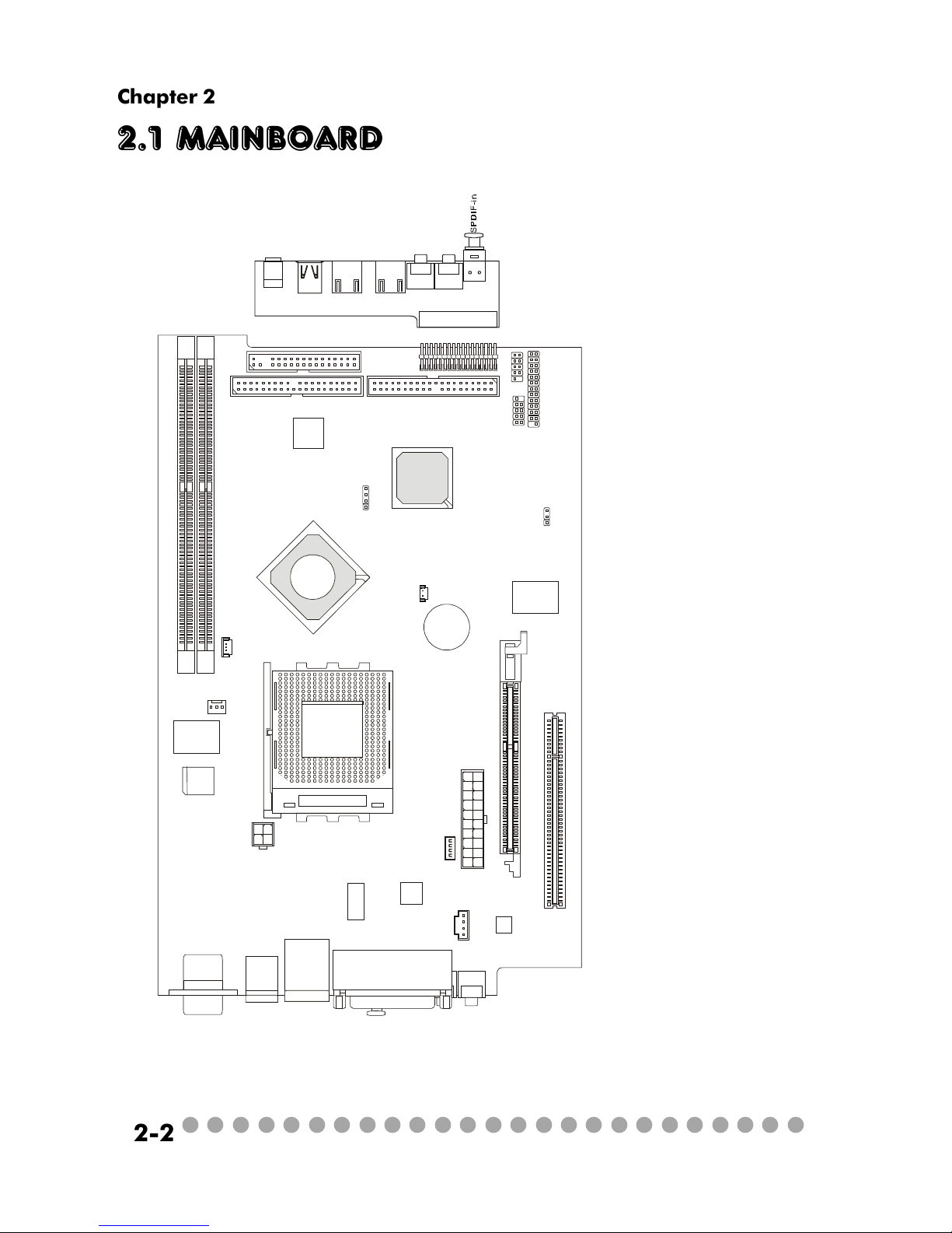
2.1 Mainboard layout
MS-6749 v1.X Mainboard
J9: Front I/O Connector
J8: Control Board Connector
JFP1: Front Panel Power Connector
J2: USB Connector
(reserved)
JBAT1: Clear CMOS Jumper
CN31: System Fan Connector
CN30: CPU Fan2
PCI Slot1:PCI Slot
AGP Slot: AGP Slot
U11: Standby Power Connector
JCD1:CD-in Connector
CPUFAN1: CPU Fan1
JPW1: Power Supply Connector
IDE1/IDE2: IDE Connectors
DDR1/DDR2: DDR DIMM Slots
J
1
C
N
1
A
U
D
I
O
1
A
U
D
I
O
2
U
S
B
1
U
S
B
2
J
1
3
9
4
-
1
J
1
3
9
4
-
2
M
i
c
-
i
n
H
e
a
d
p
h
o
n
e
D
D
R
1
D
D
R
2
C
P
U
F
A
1
J
P
W
1
C
N
3
0
C
N
3
1
T
o
p
:
m
o
u
s
e
B
o
t
t
o
m
:
k
e
y
b
o
a
r
d
T
:
R
J
4
5
L
A
N
j
a
c
k
B
:
U
S
B
p
o
r
t
s
J
C
D
1
U
1
1
C
o
d
e
c
V
I
A
V
T
6
1
0
3
V
I
A
V
T
1
6
2
2
A
M
VIA
VT6307
W
i
n
b
o
n
d
W
8
3
6
9
7
H
F
BATT
+
B
I
O
S
I
D
E
1
I
D
E
2
F
D
D
1
P
C
I
S
l
o
t
1
A
T
X
P
o
w
e
r
S
u
p
p
l
y
J
F
P
1
J
8
J
2
J
9
JBAT1
T
o
p
:
C
O
M
A
B
o
t
t
o
m
:
V
G
A
P
o
r
t
T
o
p
:
P
a
r
a
l
l
e
l
P
o
r
t
B
o
t
t
o
m
:
S
P
D
I
F
O
u
t
L
i
n
e
_
O
u
t
L
i
n
e
_
I
n
M
I
C
S
O
C
K
E
T
4
6
2
A
G
P
S
l
o
t
J
1
B
l
u
e
B
i
r
d
V
L
+
V
I
A
K
M
4
0
0
V
I
A
V
T
8
2
3
5
Page 15

○○○○○○○○○○○○○○○○○○○○○○○○○
2-3
Introducing Mainboard
2.2 CPU
The system supports AMD® AthlonTM, DuronTM, AthlonTM XP up to 3000+
processors in the 462-pin package. The mainboard uses a CPU socket called
Socket 462 for easy CPU installation. When you are installing the CPU, make
sure the CPU has a heat sink and a cooling fan attached on the top to prevent
overheating.
CPU Clock Frequency Selection
The hardware configuration for CPU clock frequency of the motherboard
is set to 133/166MHz by auto detect. Therefore, to make a 133MHz CPU run at
133MHz when it is installed on the board, you have to adjust the CPU clock
frequency through jumpers. To set the clock frequency for the installed CPU,
refer to Jumpers in later section.
As processor technology pushes to faster speeds and higher
performance, thermal management becomes increasingly crucial when
building computer systems. Maintaining the proper thermal environment is key to reliable operation. As such, the processor must be maintained in the specified thermal requirements.
AMD Athlon™/Duron™/Athlon™ XP processor with a speed of
600MHz and above requires a LARGER heatsink and fan. You also
need to add thermal grease between the CPU and heatsink to improve
heat dissipation. Then, make sure that the CPU and heatsink are securely fastened and in good contact with each other. These are needed
to prevent damaging the processor and ensuring reliable operation. If
you want to get more information on the proper cooling, you can visit
AMD’s website for reference.
Thermal Issue for CPU
WARNING!
Page 16

○○○○○○○○○○○○○○○○○○○○○○○○○
2-4
Chapter 2
1. Please turn off the power and
unplug the power cord before installing the CPU.
2. Pull the lever sideways away
from the socket. Make sure to raise
the lever up to a 90-degree angle.
3. Look for the gold arrow. The
gold arrow should point towards the
lever pivot. The CPU can only fit in
the correct orientation.
4. If the CPU is correctly installed,
the pins should be completely embedded into the socket and can not be
seen.
Any violation of the correct installation procedures may cause permanent damages to your mainboard.
5. Press the CPU down firmly into
the socket and close the lever.
Always close the lever with
your fingers pressing tightly on top of
the CPU to make sure the CPU is properly and completely embedded into
the socket.
CPU Installation Procedures
Open Lever
Gold arrow
Gold arrow
90 degree
Correct CPU placement
Incorrect CPU placement
Gold arrow
Sliding
Plate
Close
Lever
Press down
the CPU
X
O
Page 17

○○○○○○○○○○○○○○○○○○○○○○○○○
2-5
Introducing Mainboard
2.3 Memory
The mainboard provides 2 slots for 184-pin DDR SDRAM DIMM (Double
In-Line Memory Module) modules and supports the memory size up to 2GB. You
can install PC2700/DDR333, PC2100/DDR266 modules into the DDR DIMM
slots (DIMM1&DIMM2).
Memory Speed/CPU FSB Support Matrix
DDR266 DDR333
FSB266 V V
FSB333 V V
Introduction to DDR SDRAM
DDR (Double Data Rate) SDRAM is similar to
conventional SDRAM, but doubles the rate by
transferring data twice per cycle. It uses 2.5 volts as
opposed to 3.3 volts used in SDR SDRAM, and
requires 184-pin DIMM modules rather than 168-pin
DIMM modules used by SDR SDRAM. High memory
bandwidth makes DDR an ideal solution for high
performance PC, workstations and servers.
D
I
M
M
2
D
I
M
M
1
DIMM Module Combination
Install at least one DIMM module on the slots. You can install either
single- or double-sided modules in any order to meet your own needs. Memory
modules can be installed in any combination as follows:
S: Single Side
D: Double Side
Slot Memory Module Total Memory
DIMM 1 DDR S/D 64MB~1GB
(Bank 0 & 1)
DIMM 2 DDR S/D 64MB~1GB
(Bank 2 & 3)
Maximum System Memory Supported 64MB~2GB
Page 18

○○○○○○○○○○○○○○○○○○○○○○○○○
2-6
Chapter 2
2.4 Power Supply
The system is equipped with a 200W(PFC) ATX power supply. The power
cord of power supply has been connected to the connector JWR1 on the mainboard
when shipped out. Except the 20-pin connector JWR1, you can find another
4-pin power connector JPW1 on the mainboard.
1
11
JWR1
20
10
PIN SIGNAL
11 3.3V
12 -12V
13 GND
14 PS_ON
15 GND
16 GND
17 GND
18
19 5V
20 5V
PIN SINGAL
1 3.3V
2 3.3V
3 GND
45V
5 GND
65V
7 GND
8 PW_OK
9 5V_SB
10 12V
JWR1 Pin Definition
PIN SINGAL
1 GND
2 GND
312V
412V
JPW1 Pin Definition
1
3
4
2
JPW1
Dimension 70 (H)x1450(W)x105(D) mm
PFC Yes (passive)
Wattage 200W Max
Electrical Design Specification AC Output :100-127/200-240 VAC, Switch
Selectable,
Auto Protection
DC Output :+3.3V 17A
:+5V 12A
:+12V 13.5A
:-12V 0.5A
:+5Vsb 3A
:+12Vsb 2.5A
80 mm PWM Fan
Certificate FCC/UL/CUL/BSMI/CB/NEMKO/TUV
Power Supply Specification
Page 19

○○○○○○○○○○○○○○○○○○○○○○○○○
2-7
Introducing Mainboard
2.5 Front panel
The Front Panel is independent and extended from the mainboard. It’s
connected to the Front I/O Connector on the mainboard. You can find the
following ports on the Front Panel.
Optical SPDIF-In
Mic-In
Head-Phone
USB x 2 J1394-1 J1394-2
IEEE 1394 Port: J1394-2
The mainboard provides two IEEE 1394 ports. This smaller one is designed for you to connect the IEEE 1394 device with external power. The IEEE
1394 high-speed serial bus complements USB by providing enhanced PC connectivity for a wide range of devices, including consumer electronics audio/
video (A/V) appliances, storage peripherals, other PCs, and portable devices.
Software Support
IEEE 1394 Driver is provided by Windows® 98 SE, Windows® XP, Windows® ME and Windows® 2000. Just plug in
the IEEE 1394 connector into the port. These Operating Systems will install the driver for IEEE 1394.
Page 20

○○○○○○○○○○○○○○○○○○○○○○○○○
2-8
Chapter 2
IEEE 1394 Port: J1394-1
The bigger 6-pin IEEE 1394 Port on the back panel is designed for you to
connect to IEEE 1394 devices without external power. That means the mainboard
can provide the power for the devices connected to this port.
Software Support
IEEE 1394 Driver is provided by Windows® 98 SE, Windows® XP, Windows® ME and Windows® 2000. Just plug
in the IEEE 1394 connector into the port. These Operating
Systems will install the driver for IEEE 1394.
USB Ports
The mainboard provides an OHCI (Open Host Controller Interface) Universal Serial Bus root for attaching USB devices such as keyboard, mouse or
other USB-compatible devices. You can plug the USB device directly into the
connector.
USB Port Description
PIN SIGNAL DESCRIPTION
1 VCC +5V
2 -Data 0 Negative Data Channel 0
3 +Data 0 PositiveData Channel 0
4 GND Ground
5 VCC +5V
6 -Data 1 Negative Data Channel 1
7 +Data 1 PositiveData Channel 1
8 GND Ground
Page 21

○○○○○○○○○○○○○○○○○○○○○○○○○
2-9
Introducing Mainboard
Mic-in/Head-Phone
Mic-in is a connector for microphone. Head-Phone is a connector for
Speakers or Headphones.
OPTICAL SPDIF-in
The OPTICAL connector allows you to receive the audio file of SPDIF
interface for recording and playing.
The SPDIF (Sony & Philips Digital Interface) is developed jointly by the
Sony and Philips corporations . A standard audio file transfer format, SPDIF
allows the transfer of digital audio signals from one device to another without
having to be converted first to an analog format.
Page 22

○○○○○○○○○○○○○○○○○○○○○○○○○
2-10
Chapter 2
2.6 Back panel
The Back Panel provides the following ports:
VGA Port
Keyboard
USB x 2
Optical SPDIF-out
Speaker-out
Line-in
Mic-in
Parallel Port
LAN Port
Mouse
Serial Port
S-Video out
9-Pin Male DIN Connector
1 2 3 4 5
6 7 8 9
Serial Port
The mainboard offers a 9-pin male DIN serial port . The port is 16550A
high speed communication ports that sends/receives 16 bytes FIFOs. You can
attach a serial mouse or other serial devices directly to the connector.
PIN SIGNAL DESCRIPTION
1 DCD Data Carry Detect
2 SIN Serial In or Receive Data
3 SOUT Serial Out or Transmit Data
4 DT R Data Terminal Ready
5 GN D Ground
6 DSR Data Set Ready
7 RTS Request To Send
8 CTS Clear To Send
9 RI Ring Indicate
Pin Definition
Page 23

○○○○○○○○○○○○○○○○○○○○○○○○○
2-11
Introducing Mainboard
Mouse/Keyboard Connectors
The mainboard provides two standard mini DIN connectors for attaching
PS/2® mouse and keyboard. You can plug a PS/2® mouse or keyboard directly
into the connector.
PIN SIGNAL DESCRIPTION
1 Mouse DATA Mouse DATA
2 NC No connection
3 GND Ground
4 VCC +5V
5 Mouse Clock Mouse clock
6 NC No connection
Pin Definition
PS/2 Mouse (6-pin Female)
2
1
3
4
5
6
PIN SIGNAL DESCRIPTION
1 Keyboard DATA Keyboard DATA
2 NC No connection
3 GND Ground
4 VCC +5V
5 Keyboard Clock Keyboard clock
6 NC No connection
Pin Definition
PS/2 Keyboard (6-pin Female)
2
1
3
4
5
6
Pin Definition
Analog Video Display Connector (DB-15s)
PIN SIGNAL DESCRIPTION
1 Red
2 Green
3 Blue
4 Not used
5 Ground
6 Ground
7 Ground
8 Ground
9 Power
10 Ground
11 Not used
12 SDA
13 Horizontal Sync
14 Vertical Sync
15 SCL
DB 15-Pin Female Connector
5 1
15 11
VGA Port
The mainboard provides one DB 15-pin female connector to connect a
VGA monitor.
Page 24

○○○○○○○○○○○○○○○○○○○○○○○○○
2-12
Chapter 2
OPTICAL SPDIF-out
The OPTICAL connector allows you to play the audio file of SPDIF interface.
It also supports Dolby Digital audio stream under RealTek driver.
The mainboard provides one standard RJ-45 jack for connection to Local
Area Network (LAN). You can connect a network cable to the LAN jack.
Pin Definition
PIN SIGNAL DESCRIPTION
1 TDP Transmit Differential Pair
2 TDN Transmit Differential Pair
3 RDP Receive Differential Pair
4 NC Not Used
5 NC Not Used
6 RD N Receive Differential Pair
7 NC Not Used
8 NC Not Used
LAN Port
S-Video Out Connector
You can connect to a TV or video device to S-Video out connector for
video-out function which allows you to output the image to a TV or video device.
The connector supports the formats including NTSC-M, NYSC-J, PAL, PAL-M,
PAL-N, PAL-Nc.
TV
Projector
Page 25

○○○○○○○○○○○○○○○○○○○○○○○○○
2-13
Introducing Mainboard
Parallel Port
The mainboard provides a 25-pin female centronic connector as LPT. A
parallel port is a standard printer port that supports Enhanced Parallel Port (EPP)
and Extended Capabilities Parallel Port (ECP) mode.
PIN SIGNAL DESCRIPTION
1 STROBE Strobe
2 DATA0 Data0
3 DATA1 Data1
4 DATA2 Data2
5 DATA3 Data3
6 DATA4 Data4
7 DATA5 Data5
8 DATA6 Data6
9 DATA7 Data7
10 ACK# Acknowledge
11 BUSY Busy
12 PE Paper End
13 SELECT Select
14 AUTO FEED# Automatic Feed
15 ERR# Error
16 INIT# Initialize Printer
17 SLIN# Select In
18 G ND Ground
19 G ND Ground
20 G ND Ground
21 G ND Ground
22 G ND Ground
23 G ND Ground
24 G ND Ground
25 G ND Ground
Pin Definition
14
25
13 1
Page 26

○○○○○○○○○○○○○○○○○○○○○○○○○
2-14
Chapter 2
Audio Port
Speaker-out is a connector for Speakers or Headphones. Line-in is used
for external CD player, Tape player, or other audio devices. Mic-in is a connec-
tor for microphones. These three ports can also be used for 5.1 channel audio
output.
NOTE: When used for 5.1 channel audio output, Speaker-out is used for “left/
right”, Line-in is used for “surround left/right” while Mic-in is used for “Center/
LFE (Subwoofer).
Speaker-out
Line-in Mic-in
USB Ports
The mainboard provides two USB2.0 EHCI/USB1.1 OHCI Universal Serial Bus root for attaching USB devices such as keyboard, mouse or other USBcompatible devices. You can plug the USB device directly into the connector.
USB Ports
1 2 3 4
5 6 7 8
USB Port Description
PIN SIGNAL DESCRIPTION
1 VCC +5V
2 -Data 0 Negative Data Channel 0
3 +Data 0 PositiveData Channel 0
4 GND Ground
5 VCC +5V
6 -Data 1 Negative Data Channel 1
7 +Data 1 PositiveData Channel 1
8 GND Ground
Page 27

○○○○○○○○○○○○○○○○○○○○○○○○○
2-15
Introducing Mainboard
2.7 Connectors
IDE1 (Primary IDE Connector)
- IDE1 can only connect a HDD.
IDE2 (Secondary IDE Connector)
- IDE2 can only connect a CD-ROM drive.
IDE Connectors: IDE1 & IDE2
The mainboard has a 32-bit Enhanced PCI IDE and Ultra DMA 33/66/100/
133 controller that provides PIO mode 0~4, Bus Master, and Ultra DMA/33/66/
100/133 function. The two connectors on the mainboard allows you to connect
to two IDE devices.
IDE1
IDE2
If you install two hard disks on cable, you must configure the second drive to Slave mode by setting its jumper.
Refer to the hard disk documentation supplied by hard
disk vendors for jumper setting instructions.
Page 28

○○○○○○○○○○○○○○○○○○○○○○○○○
2-16
Chapter 2
CD-in Connector: JCD1
The connector is for CD-ROM audio connector.
CPU/System Fan Connectors: CPUFAN1/CN31/CN30
The CPU and System Fan connectors support system cooling fans with
+12V that is controlled by PWM. When connecting the wire to the three-pin
head connectors, always note that the red wire is the positive and should be
connected to the +12V (that is controlled by PWM), the black wire is Ground
and should be connected to GND.
JCD1
GND
R
L
CPUFAN1 CN30/CN31
SENSOR
+12V
GND
+12V
SENSOR
GND
Standby Power Connector: U11
The mainboard provides a connector to connect the Standby power.
+12VSBY
GND
5VSB
Page 29

○○○○○○○○○○○○○○○○○○○○○○○○○
2-17
Introducing Mainboard
Front Panel Power Connector: JFP1
The mainboard provides a Front Panel connector for electrical connection to the Front Panel switches and LEDs. JFP1 is compliant with Intel® Front
Panel I/O Connectivity Design Guide.
PIN SIGNAL DESCRIPTION
1 HD_LED_P Hard disk LED pull-up
2 FP PWR/SLP MSG LED pull-up
3 HD_LED_N Hard disk active LED
4 FP PWR/SLP MSG LED pull-up
5 RST_SW_N Reset Switch low reference pull-down to GND
6 PWR_SW_P Power Switch high reference pull-up
7 RST_SW_P Reset Switch high reference pull-up
8 PWR_SW_N Power Switch low reference pull-down to GND
9 RSVD_DNU Reserved. Do not use.
JFP1 Pin Definition
1
910
JFP1
HDD
LED
Reset
Switch
Power LED
Power
Switch
2
Control Board Connector: J8
The connector is used to connect the Control Board on the front panel.
J8
1
25
26
VCC3SBY
2
SPI Bus
CD_SMI
VCC5
HDLED
PWRBTNH
FP_RST
Power LED
LED-BL
VCC5SBY
IR
GND
GND
Key (0-~5)
GND
+12VSBY
Power LED
Page 30

○○○○○○○○○○○○○○○○○○○○○○○○○
2-18
Chapter 2
2.8 Jumpers
There is a CMOS RAM on board that has a power supply from external
battery to keep the data of system configuration. With the CMOS RAM, the
system can automatically boot OS every time it is turned on. That battery has
long life time for at least 2 years. If you want to clear the system configuration,
use the JBAT1 (Clear CMOS Jumper ) to clear data. Follow the instructions below to clear the data:
Clear Data
1
3
Keep Data
1
3
Clear CMOS Jumper: JBAT1
You can clear CMOS by shorting 2-3 pin while the
system is off. Then return to 1-2 pin position. Avoid
clearing the CMOS while the system is on; it will
damage the mainboard.
J1
CPU FSB Mode Jumper: J1
This jumper allows you to set the CPU FSB mode.
133/166 MHz
(auto detect, default)
100 MHz
1
4
1
4
1
4
166 MHz
Page 31

○○○○○○○○○○○○○○○○○○○○○○○○○
2-19
Introducing Mainboard
2.9 Slots
PCI Slot 1
AGP (Accelerated Graphics Port) Slot
The AGP slot allows you to insert the AGP graphics
card. AGP is an interface specification designed for the
throughput demands of 3D graphics. It introduces a 66MHz,
32-bit channel for the graphics controller to directly access
main memory and provides three levels of throughputs: 1x
(266Mbps), 2x (533Mbps) , 4x (1.07Gbps) and 8x.
PCI Slot
The PCI slot allows you to insert PCI card or TV Tuner
card.
When adding or removing expansion cards, make sure
that you unplug the power supply first. Meanwhile, read the
documentation for the expansion card to make any necessary hardware or software settings
NOTE: You can install the OPTIONAL MS8606 card into
the PCI slot to enjoy watching TV.
AGP Slot
Page 32

3-1
Setting BIOS Function
Setting BIOS Function
3.1 Entering Setup
3.2 The Main Menu
3.3 Standard CMOS Features
3.4 Advanced BIOS Features
3.5 Advanced Chipset Features
3.6 Power Management Features
3.7 PnP/PCI Configurations
3.8 Integrated Peripherals
3.9 PC Health Status
3.10 System Information
Page 33

3-2
Chapter 3
3.1 Entering Setup
Power on the co mputer and th e system will start POST (Power On Self
Test) process. When the message below appears on the screen, press <DEL> key
to enter Setup.
Press DEL to enter SETUP
If the message disappears before you respond and you still wish to enter
Setup, restart the system by turning it OFF and On or pressing the RESET button.
You may also restart the system by simultaneously pressing <Ctrl>, <Alt>, and
<Delete> keys.
Control Keys
<↑> Move to the previo us i tem
<↓> Move to the next ite m
<←> Move to the item in the left hand
<→> Move to the item in the right hand
<Enter> Select the item
<Esc> Jumps to the Exit menu or returns to the main
menu from a submenu
<-/PD> Decrease the num eric value or make changes
<+/PU> Increase the numeric value or make changes
<F7> Load BIOS Setup De faults
<F9> Load High P erformance Defaults
<F10> Save all the CMOS changes and exit
Page 34

3-3
Setting BIOS Function
Getting Help
After entering the Setup menu, the first menu you will see is the Main
Menu.
Main Menu
The main menu lists the setup functions you can make changes to. Y ou
can use the control keys ( ↑↓ ) to select the item. The on-line description of the
highlighted setup function is d isplayed at the bottom of the screen.
Sub-Menu
If you find a right pointer symbol (as shown in the right view) appears to the left
of certain fields that means a sub-menu containing additional options can be
launched from this field. You can use control keys (↑↓ ) to highlight the field
and press <Enter> to call up the sub-menu. Then you can use the control keys
to enter values and move from field to field within a sub-menu. If you want to
return to the main menu, just press <Esc >.
8IDE Primary Master
8IDE Primary Slave
8IDE Secondary Master
8IDE Secondary Slave
General Help <F1>
The BIOS setup program provides a General Help screen. You can call
up this screen from any menu by simply pressing <F1>. The Help screen lists the
appropriate keys to use and the possible selections for the highlighted item.
Press <Esc> to exit the Help screen.
Page 35

3-4
Chapter 3
3.2 The main menu
Once you enter BIOS CMOS Setup Utility, the Main Menu (Figure 1) will
appear on the screen. The Main Menu allows you to select from twelve setup
functions and two exit choices. Use arrow keys to select among the items and
press <Enter> to accept or enter the sub-menu.
Standard CMOS Features
Use this menu for basic system con figurations, such as time, date etc.
Advanced BIOS Features
Use this menu to setup th e items of special enhanced features.
Advanced Chipset Features
Use this menu to ch ange the values in the chipset registers and optimize your
system’s performance.
Power Management Features
Use this menu to specify your settings for p ower managemen t.
Page 36

3-5
Setting BIOS Function
PnP/PCI Configurations
This entry appears if your system supports PnP/PCI.
Integrated Peripherals
Use this menu to specify you r settings for integrated peripherals.
PC Health Status
This entry shows your PC health status.
System Information
This entry shows the system information.
Set Supervisor Password
Use this menu to set Supervisor Password.
Set User Password
Use this menu to set User Password.
Load Optimal Defaults
Use this menu to load the BIOS values for th e best system performance, but the
system stability may be affected.
Load Fail Safe Defaults
Use this menu to load factory default settings into the BIOS for stable system
performance operations.
Save & Exit Setup
Save changes to CMOS and exit setup.
Exit Without Saving
Abandon all changes and exit setup.
Page 37

3-6
Chapter 3
3.3 standard cmos features
The items in Standard CMOS Features Menu are divided into 14 categories.
Each category in cludes no, one or more than one setup items. Use the arrow
keys to highlight th e item and then use the <PgUp> or <PgDn> keys to select
the value you want in each item.
System Time
This allows you to set the system time that you want (usually the current time).
The time format is <hour> <minute> <second>.
System Date
This allows you to set th e system to the date that you want (usually the current
date). The format is <day><mon th> <date> <year>.
Primary/Secondary IDE Master/Slave
Press PgUp/<+> or PgDn/< -> to select Manual, None or Auto type. Note that
the specifications of your drive must match with the drive table. The hard disk
will not work properly if you enter improper information for this category. If
your hard disk drive type is not matched or listed, you can use Manual to define
your own drive type manually.
Page 38

3-7
Setting BIOS Function
If you select Manual, related information is asked to be entered to the following
items. Enter the information directly from the keyboard. This information should
be provided in the documentation from your hard disk vendor or the system
manufacturer.
Access Mode The settings are CHS, LBA , Large, Auto.
Capacity The formatted size of the storage device.
Cylinder Number of cylinders.
Head Number of heads.
Precomp Write precompensation.
Landing Zone Cylinder location of the landing zone.
Sector Number of sectors.
Current Language
This allows you to switch the language of BIOS. Setting options: English, China
(Simplified Chinese), Chinese (Traditional Chinese), Japanese, Korea.
Page 39

3-8
Chapter 3
3.4 advanced bios features
Quick Boot
Setting the item to Enabled allows the system to boot within 5 seconds since it
will skip some check items. Available options: Enabled, Disabled.
Full Screen Logo Show
This item enables you to show the company logo on the bootup screen. Settings
are:
Enabled Shows a still image (logo) on the full screen at boot.
Disabled Shows the POST messages at boot.
Anti-Virus Protection
The item is to set the V irus Warning feature for IDE Hard Disk boot sector
protection. If the function is enabled and any attempt to write data into this area
is made, BIOS will display a warning message on screen and beep. Settings:
Disabled and Enabled.
Page 40

3-9
Setting BIOS Function
Boot Device Priority
1st/2nd/3rd Boot Device
The items allow you to set the sequence of boot devices where BIOS
attempts to load the disk operatin g system. If you select boot from USB
device, USB Device Legacy Support must be set to Enabled.
Try Other Boot Devices
Setting the option to Enabled allows the system to try to boot from other
device if the system fails to boot from the 1st/2nd/3rd boot device.
Hard Disk S.M.A.R.T.
This allows you to activate the S.M.A.R.T. (Self-Monitoring Analysis & Reporting Technology) capability for the hard disks. S.M.A.R.T is a utility that monitors
your disk status to predict hard disk failure. This gives you an opportunity to
move data from a hard disk th at is going to fail to a safe place before the hard
disk becomes offline. Settings: Enabled and Disabled.
BootUp Num-Lock LED
This setting is to set the Num Lock status when the system is powered on. Setting to On will turn on the Num Lock key when the system is powered on.
Setting to Off will allow users to use the arrow keys on the numeric keypad.
Page 41

3-10
Chapter 3
Security Option
This specifies th e type of B IOS password protection that is implemented. Settings are described below:
Boot to OS/2 for DRAM > 64MB
This allows you to run the OS/2® operating system with DRAM larger than 64MB.
When you choose No, you cannot run the OS/2® operating system with DRAM
larger than 64MB. But it is p ossible if you choose Yes.
APIC Function
This field is used to enable or disable the APIC (Advanced Programmable Interrupt Controller). Due to compliance with PC2001 design guide, the system is
able to run in APIC mode. Enabling APIC mode will expand available IRQ
resources for the system. Settin gs: Enabled and Disabled.
MPS Table Version
This field allows you to select which MPS (Multi-Processor Specification) version to be used for the operating system. You need to select the MPS version
supported by your operating system. To find out which version to use, consult the
vendor of your operating system. Settings: 1.4, 1.1.
Option Description
Setup The password prompt appears only when end users try
to run Setup.
System A password prompt appears every t ime when the com-
puter is powered on or when end users try to run Setup.
Page 42

3-11
Setting BIOS Function
3.5 advanced chipset features
NOTE: Change these settings only if you are familiar with the chipset.
Spread Spectrum
This item is used to enable or disable the FSB clock generator’s Spread Spectrum
feature. Wh en overclocking the FSB , always set it to Disabled. Options:
Disabled, ±0.25%, ±0.5%, ±0.75%.
PCI Delayed Transaction
The chipset has an embedded 32-bit posted write buffer to support delay transactions cycles. Select En abled to support compliance with PCI specification version 2.1.
DRAM Timing Control
Press <Enter> to enter the sub-menu and the following screen appears:
Page 43

3-12
Chapter 3
Configure SDRAM Timing by SPD
Selects whether DRAM timing is controlled by the SPD (Serial Presence
Detect) EEPROM on the DRAM module. Setting to SPD enables
SDRAMFrequency, SDR AM CAS Latency and SDRAM Bank Interleave
automatically to be determined by BIOS based on the configurations on
the SPD. Selecting User allows users to co nfigure these fields manually.
SDRAM Frequency
Use this item to configure the clock frequency of the installed SDRAM.
Settings options: 266MHz, 333MHz, Auto.
SDRAM CAS# Latency
This controls the timing delay (in clock cycles) before SDRAM starts a
read command after receiving it. Settings: Auto, 1.5, 2, 2.5, 3.0 (clocks).
2 (clocks) increases the system performance the most while 3 (clocks)
provides the most stable performance.
SDRAM Bank Interleave
This field selects 2-ban k or 4-bank interleave for the installed SDRAM.
Disable the function if 16MB SDRAM is installed. Settings: Disabled, 2-
Way and 4-Way.
Page 44

3-13
Setting BIOS Function
SDRAM Burst Length
This setting allows you to set the size of Burst-Length for DRAM. Bursting
feature is a technique that DR AM itself predicts the address of the next
memory location to be accessed after the first address is accessed. To use
the feature, you need to define the burst length, which is the actual length
of burst plus the starting address and allows internal address counter to
properly generate the n ext memory location. The bigger the size, the
faster the DRAM performance.
Settings: 4 QW, 8 QW.
SDRAM Command Rate
This setting con trols the SDRA M command rate. Selecting Enabled allows SDRAM signal controller to run at 1T (T=clock cycles) rate. Selecting Disabled makes SDRAM signal controller run at 2T rate. 1T is faster
than 2T. Setting options: Disab led, Enabled.
Fast Command
This item contro ls the internal timing of CPU. Selecting Ultra allows
CPU to handle data/instructions at the fastest speed. Fast enables CPU to
handle at a faster speed, while Normal let CPU handle them at the slowest rate.
AGP Timing Control
Press <Enter> to enter the sub-menu and the following screen appears:
Page 45

3-14
Chapter 3
AGP Fast Write
This option enables or disables the AGP Fast Write feature. The Fast Write
technology allows the CPU to write d irectly to the graphics card with out
passing anything through the system memory and improves the AGP 4X
speed. Select Enabled only when the installed AGP card supports this
function. Settings: Enabled , Disabled.
AGP Aperture Size
This setting controls just how much system RAM can be allocated to AGP
for video purposes. The aperture is a portion of the PCI memory address
range dedicated to graphics memory address space. Host cycles that hit
the aperture range are forwarded to the AGP without any translation. The
option allows the selection of an aperture size of 4MB, 8MB, 16MB, 32MB,
64MB, 128MB, and 256 MB.
AGP Master 1 W/S Write
The field allows users to insert one wait state into the AGP write cycle.
Settings: Enabled, Disabled.
AGP Master 1 W/S Read
The field allows users to insert one wait state into the AGP read cycle.
Settings: Enabled, Disabled.
AGP Read Synchronization
The field allows you to enable or disable the AGP Read Synchro nization
feature. Settings: Enabled, Disabled.
OnChip VGA Frame Buffer Size
Frame Buffer is the video memory that stores data for video display (frame).
This field is used to determine the memory size for Frame Buffer. Larger
frame buffer size increases video performance. Settings: 8M, 16M, 32MB,
64MB.
Page 46

3-15
Setting BIOS Function
TV-Out Function
Press <Enter> to enter the sub-menu and the following screen appears:
Boot Display Device
This item allows yo u to select th e Boot Display Device. Options: CRT,
TV.
TV Type
Select the TV standard which is used as the video signal format of your TV
if you have connected a TV to the system. Options: NTSC, PA L, PALM,
PALN, PALNc.
TV Output Connector
This item allows you to select the type of TV output connector. Options:
S-Video, Composite.
Page 47

3-16
Chapter 3
3.6 Power management features
Sleep State
This item specifies the power saving modes for ACPI function. Options are:
S1/POS The S1 sleep mode is a low power state. In this state, no
system context is lost (CPU or chipset) and hardware main
tains all system context.
S3/STR The S3 sleep mode is a lower power state where the infor
mation of system configuration and open applications/files
is saved to main memory that remains powered while most
other hardware components turn off to save energy. The
information stored in memory will be used to restore the
system when a “wake up” event occurs.
Auto The system will decide when to enter S1 or S3 state.
Page 48

3-17
Setting BIOS Function
Set WakeUp Events
Press <Enter> to enter the sub-menu and the following screen appears:
Wake Up On PME, Wake Up By Keyboard (with “Wake-Up Key” and
“Wake-Up Password”), Wake Up By PS/2 Mouse
These fields specify whether the system will be awakened from power
saving modes when activity or input signal of the specified hardware
peripheral or component is detected. Settings: Enabled, Disabled.
Resume By Alarm
This is used to enable or disable the feature of booting up the system on a
scheduled time/date from the soft off (S5) state. Settings: Enabled, Disabled.
Alarm Date/Hour/Minute/Second
If Resume By Alarm is set to Enabled, the system will automatically resume (boot up) on a specific date/hour/minu te/second specified in these
fields. Available settings for each item are:
Alarm Date 01 ~ 31, Every Day
Alarm Hour 00 ~ 23
Alarm Minute 00 ~ 59
Alarm Second 00 ~ 59
Page 49

3-18
Chapter 3
3.7 PNP/PCI Configurations
Clear NVRAM
The ESCD (Extended System Configuration Data) NVRAM (Nonvolatile Random
Access Memory) is where the BIOS stores resource information for both PNP and
non-PNP devices in a bit string format. When the item is set to Yes, the system
will reset ESCD NVRAM right after the system is booted up and then set the
setting of the item back to No automatically.
Page 50

3-19
Setting BIOS Function
3.8 Integrated peripherals
On-Chip IDE
This settin g controls the onboard IDE controller. Setting options: Disabled,
Primary, Secondary, Both.
Onboard LAN Controller
This setting contro ls th e onb oard LAN controller. Setting options: Disabled,
Enabled.
OnBoard LAN P.M.E
This setting controls the power management function of LAN. Setting “Enabled
” allows you to wake up the system th rough LAN.
Onboard LAN ROM
This setting controls the power management function of LAN. Setting “Enabled
” allows you to boot the system through LAN.
Page 51

3-20
Chapter 3
OnBoard AC’97 Audio
Select Enabled to use the audio capabilities of your system. Most of the following fields do not appear when this field is Disabled.
OnBoard 1394 Controller
This setting controls the onboard 1394 device. Setting options: Disabled, Enabled.
USB Controller
This setting is used to enable/disable the onboard USB controller. Setting options:
Disabled, Enabled.
USB Device Legacy Support
Set to Enabled if your need to use any USB 1.1/2.0 device in the operating
system that does not support or h ave any USB 1.1/2.0 driver installed, such as
DOS and SCO Unix. Set to Disabled only if you want to use any USB device
other than the USB mouse. Setting options: Disabled, Enabled.
Set Super I/O
Press <Enter> to enter the sub-menu and the following screen appears:
Page 52

3-21
Setting BIOS Function
Serial Port 1
These items specify the base I/O port addresses of the onboard Serial Port
1 (COM A)/Serial P ort 2 (COM B). Selecting Auto allows AMIBIOS to
automatically determine the correct base I/O port address. Settings: Auto,
3F8/COM1, 2F8/COM2, 3E8/COM3, 2E8/COM4 and Disabled.
Parallel Port
This field specifies the base I/O port address of the onboard parallel po rt.
Selecting Auto allows AMIBIOS to automatically determine the correct
base I/O port address. Settings: Auto, 3 78, 278, 3BC, Disabled
Port Mode
This item selects the operation mode for the onboard parallel port: ECP,
Normal, Bi-Dir or EPP.
EPP Version
The item selects the EPP version used by the parallel port if the port is set
to EPP mode. Settings: 1.7, 1.9.
Port IRQ
When OnBoard Parallel Port is set to Auto, the item shows Auto indicating that BIOS determines the IRQ for the parallel port automatically.
Port DMA
This feature needs to be configured only when Parallel Port Mode is set to
the ECP mode. When Parallel Port is set to Auto, the field will show Auto
indicating that BIOS auto matically determines the DMA channel for the
parallel port.
Page 53

3-22
Chapter 3
System/CPU Temperature, CPU Fan1/CPU Fan2 Speed, Vcore, +5.0V, +12.0V,
-12.0V, -5.0V, Battery, +5V SB
These items display the current status of all of the monito red hardware devices/
components such as CPU voltages, temperatures and all fans’ speeds.
3.9 PC health status
Page 54

3-23
Setting BIOS Function
3.10 System Information
Product Name, System BIOS Version, BlueBird F/W Version, Processor Type,
Processor Speed, Total Memory
These items shows the information about the system status, such as produ ct
name, BIOS version, processor type, processo r speed and total memory.
 Loading...