

MSI MICRO NLX BX4 User Manual

CHAPTER 1CHAPTER 1
CHAPTER 1CHAPTER 1
CHAPTER 1
INTRODUCTIONINTRODUCTION
INTRODUCTIONINTRODUCTION
INTRODUCTION
1-1
Chapter 1
INTRODUCTION
The MICRO NLX BX4 mainboard is a high-performance personal computer
mainboard based on Intel® Pentium® II processor. It combines ATI® 3D
RAGE 128VR/Rage XL/Rage Pro AGP graphics accelerator, YAMAHA
®
YMF740C PCI enhanced audio, and Intel® 82559 10/100M Ethernet . The
Pentium® II processor supports MMX
TM
(Multimedia Extension) technology .
The mainboard uses the highly integrated Intel® 82443BX chipset to support
the PCI/ISA and Green standards, and to provide the Host/AGP bridge. The
Intel® 82371EB chipset integrates all system control functions such as ACPI
(Advanced Configuration and Power Interface). The ACPI provides more
Energy Saving Features for the OSPM(OS Direct Power Management)
function. The Intel® 82371EB chipset also improves the IDE transfer rate by
supporting Ultra DMA/33 IDE that transfers data at the rate of 33MB/s.
The mainboard also supports the System Hardware Monitor Controller. This
function includes: CPU /power supply/chassis fan revolution detect, CPU/
system voltage monitor, system temperature monitor, and chassis intrusion
detect.

CHAPTER 1CHAPTER 1
CHAPTER 1CHAPTER 1
CHAPTER 1
INTRODUCTIONINTRODUCTION
INTRODUCTIONINTRODUCTION
INTRODUCTION
1.1 Mainboard Features
CPU
l Slot 1 for Pentium
®
II/III or CeleronTM processor.
l Supports 233MHz, 266MHz, 300MHz, 333MHz, 350MHz, 400MHz,
450MHz, and faster processor speeds.
l Core/Bus ratios are x2, x2.5, x3, x3.5, x4, x4.5, x5, x5.5, x6 and higher .
Switching V oltage Regulator
l On-board switching mode DC-DC Step Down Regulator .
l Conforms to Intel
®
VRM ver 8.2 specifications.
l Over-Voltage and Over-Current protection.
Chipset
l Intel
®
82440BX AGP chipset.
Clock Generator
l 66.6MHz and 100MHz clocks are supported.
Main Memory
l Supports four memory banks using two 168-pin unbuffered DIMM.
l Supports a maximum memory size of 256MB (8M x 8) or 512MB (16M x 4)
registered DIMM only .
l Supports ECC(1-bit Error Code Correct) function.
l Supports 3.3v SDRAM DIMM.
Video
l A TI
®
RAGE 128VR/Rage XL/ Rage Pro
- Running on AGP BUS.
- Onboard 8MB SGRAM (optional 4MB).
- 3D Acceleration.
- AGP 2x mode (133MHz) support pipelined and sideband protocols.
1-2

CHAPTER 1CHAPTER 1
CHAPTER 1CHAPTER 1
CHAPTER 1
INTRODUCTIONINTRODUCTION
INTRODUCTIONINTRODUCTION
INTRODUCTION
1-3
System Hardware Monitor
l This can be used with Intel
®
LDCM to monitor system voltage, system
temperature & fan rotation speed.
l This can also be used to monitor overall system status over the network.
l System temperature sensor: (TOP T ech)
- detect Pentium® II processor’s temperature.
l System voltage monitor:
- monitor CPU core voltage, CPU interface voltage, 3.3v ,+12v , +5v, VBAT
l Fan speed monitor:
- monitor control chassis fan, power fan & CPU cooling fan speed.
Power Management Features
l Doze/Standby/Suspend mode.
l System management mode compliant.
l Support APM 1.2.
l Meet ACPI spec.
l PC97/98 compliant.
Audio
l YAMAHA
®
YMF740C Audio Controller .
l Sound Blaster PRO Compatible.
l Support Plug and Play:
- stereo 16-bit A/D
- stereo 16-bit D/A
l Stereo enhancement support.
l Advanced power management.
l Maximum 32 voice xG capital wavetable.
l Synthesizer including GM compatible.

CHAPTER 1CHAPTER 1
CHAPTER 1CHAPTER 1
CHAPTER 1
INTRODUCTIONINTRODUCTION
INTRODUCTIONINTRODUCTION
INTRODUCTION
1-4
Network
l Intel
®
82559 10/100M Ethernet.
l WFW baseline & NET PC specs compliant.
l Advanced Power Management (ACPI support)
l Magic packet filtering to wake-up LAN.
l ARP & FLEXIBLE frame filtering.
l Software drivers are backwards compatible.
l IP checksumming in hardware.
Note: Requires an A TX power supply with 720mA 5VSB (5v Stand by).
Rear Mainboard Connectors
l PS/2 type keyboard/mouse connector.
l Two COM port connectors.
l One Printer port with SPP/EPP/ECP function.
l RJ-45 LAN connector .
l Audio connector
l VGA port
Dimension
l MICRO NLX Form Factor: 20.3cm(L) x 25.4cm(W) x 4 layers PCB.
Other Features
l Bulk Erase Flash ROM.
l Supports DMI.
l System W ake-up by modem.
l System W ake-up by alarm.
l Soft-power off. (W indows
®
95)
l Polyfuse function.
- this function works when the electric current is larger than 2A. It will
become an open circuit to protect your mainboard. Turn the power off for
1-3 secs for polyfuse to recover .
l LAN wake-up.
l Restore AC power loss status.
CHAPTER 1CHAPTER 1
CHAPTER 1CHAPTER 1
CHAPTER 1
INTRODUCTIONINTRODUCTION
INTRODUCTIONINTRODUCTION
INTRODUCTION
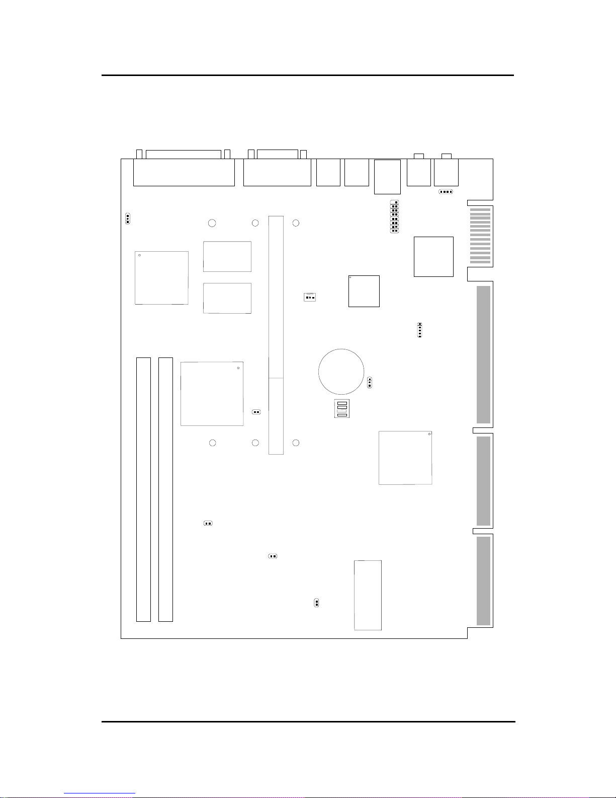
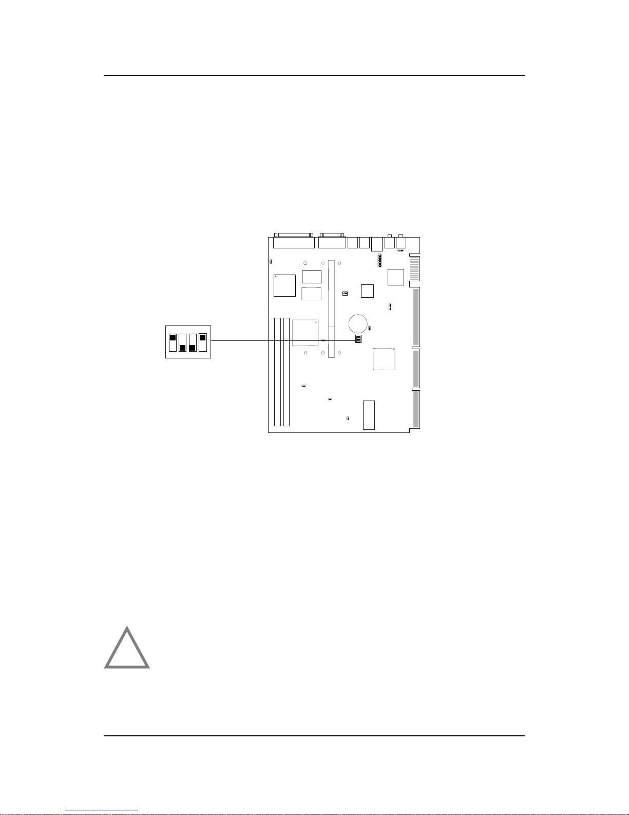
1.2 Mainboard Layout
1-5
MS-6131 Micro NLX BX6 Mainboard
SLOT 1
DIMM 2
DIMM 1
mouse
LAN
T: LPT
B: COM A
VGA Port
L-OUT
BATT
+
BIOS
FW82371EB
FW82443BX
Intel
®
82559
10/100M
Ethernet
Yamaha
YMF740C
COM B
ATI
®
Rage 128VR
Keyboard
L-IN
(optional
MIC)
JP1
SW1
JBAT1
CPUFAN
JVGA1 JAUD1
JUSB
J5
JK1
J8
JK2
SDRAM
SDRAM

CHAPTER 2 HARDWARE INSTALLATION
2-1
Chapter 2
HARDWARE INSTALLATION
2.1 Central Processing Unit: CPU
The mainboard operates with Intel® Pentium® II processor with MMX
TM
technology . The mainboard uses a CPU Slot called Slot 1 for easy CPU
installation and a DIP switch (SW1) to set the proper speed for the CPU.
The CPU should always have a Heat Sink and a cooling fan attached to
prevent overheating.
CHAPTER 2 HARDWARE INSTALLATION
2-2
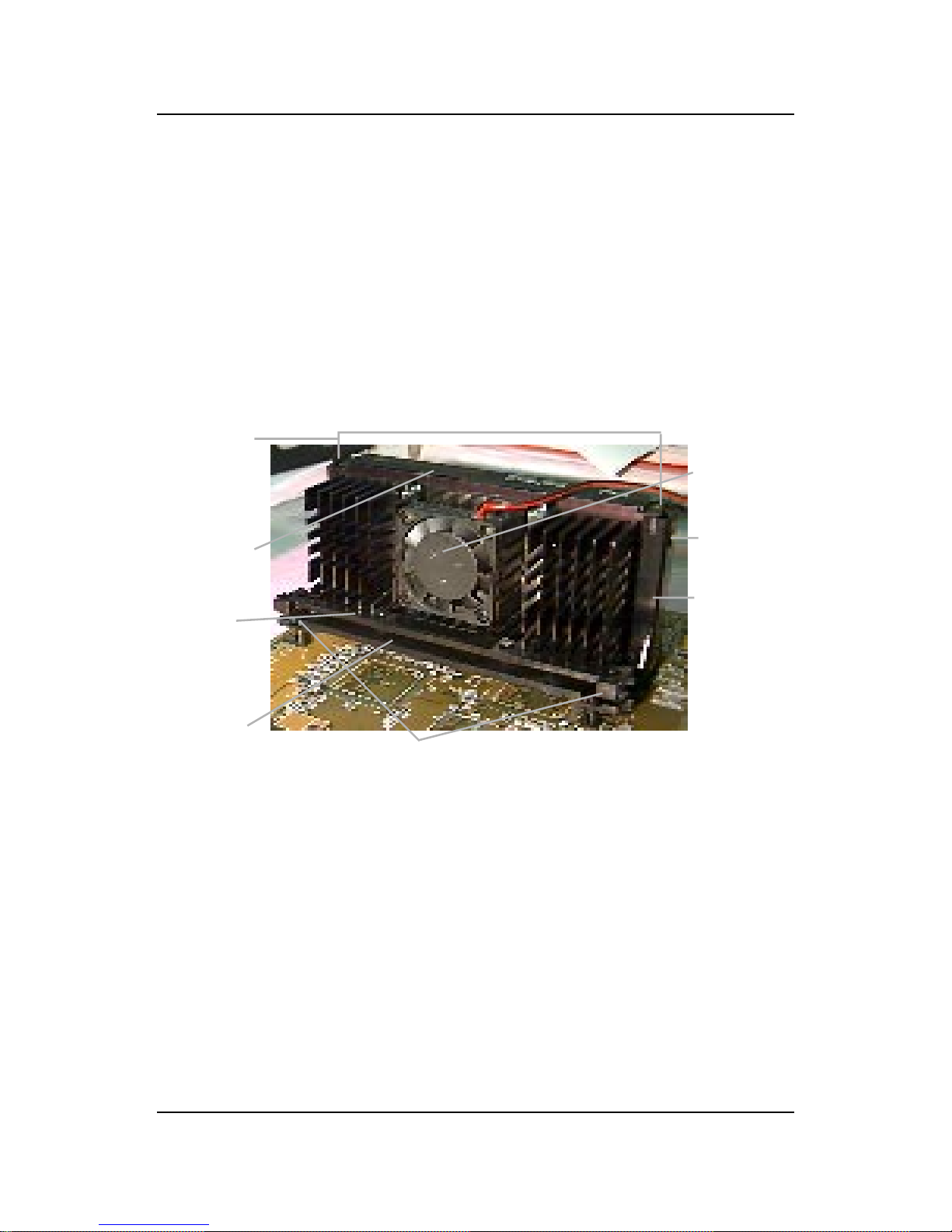
2.1-1 CPU Installation Procedures
A. OEM Pentium
®
II/III processor Installation Procedure
Required Things:
Pentium® II/III processor - Processor .
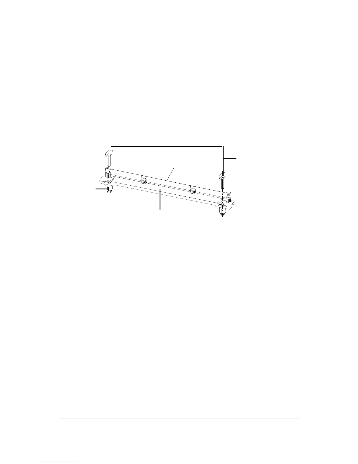
*Retention Mechanism(RM) - Plastic Guide that holds the S.E.C.
Catridge/S.E.C.C. 2 in the Slot 1 connector.
*Retention Mechanism Attach Mount(RMAM) - Bolt/Bridge assemblies
inserted up through the bottom of the
motherboard. RM secures to RMAM ( 2
RMAM required per RM ).
*Heat Sink Support Base (HSSBASE) - Plastic support bar mounted to
the mainboard under the ATX heatsink.
(One leg is always bigger than the other one)
Processor
Lock
Retention
Mechanism
Pentium® II/III
Processor
Heat Sink
W/Fan
Notch Hole
Heat Sink
Support Base
Heat Sink
Support Pin
Heat Sink
Support
Top Bar
Different kinds of Pentium® II/III processor that is currently used: the OEM
version, the Boxed version, and CeleronTM. OEM Pentium® II/III Processor
has no Heat Sink, Fan and Heat Sink Support, the Boxed Pentium® II/III
Processor is provided with Heat Sink w/ fan and Heat Sink Support, while
the CeleronTM processor is a plain processor card without cover or heatsink..
CHAPTER 2 HARDWARE INSTALLATION
2-3
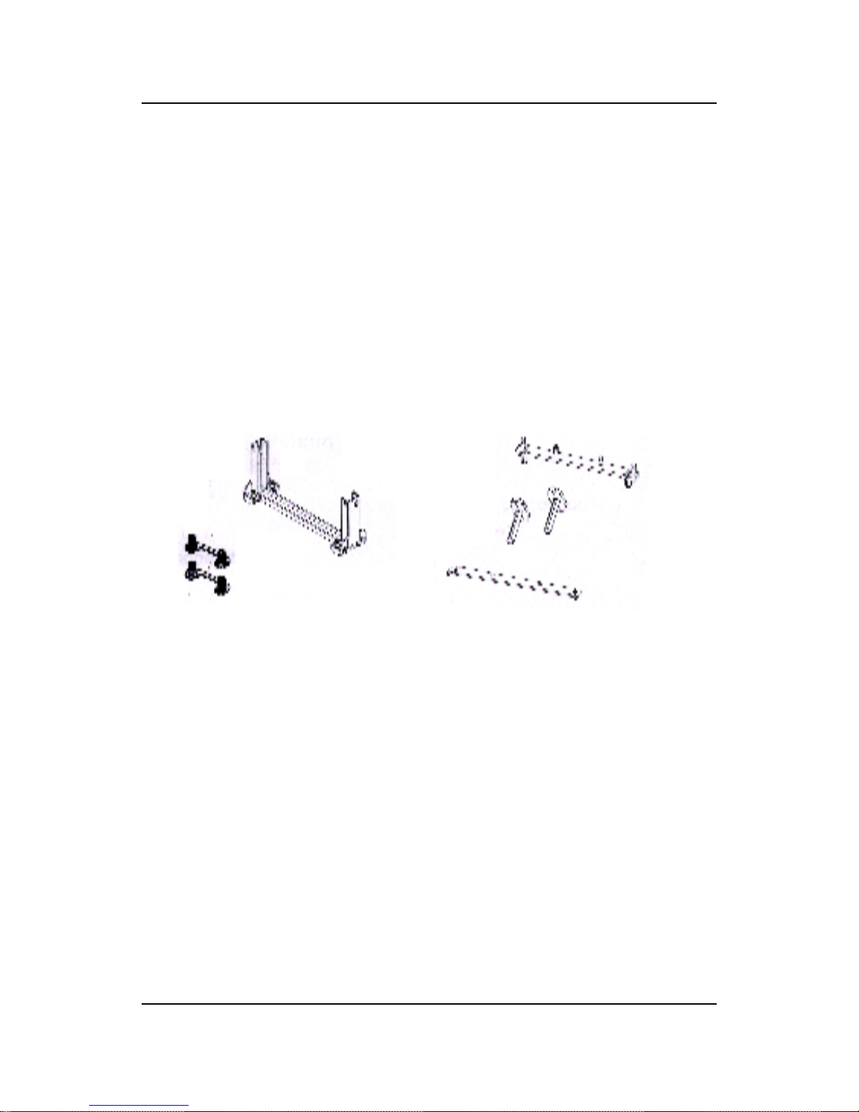
*Heat Sink Support Pin (HSSPIN) - Plastic pins inserted through the
HSSBASE to secure it to the mainboard (2
required per Assembly).
*Heat Sink Support T op Bar (HSSTOP) - Plastic bar that clips onto the
HSSBASE through the fins on the ATX
heatsink.
**Heat Sink w/ fan - Heat Sink that can be attached to the Pentium® II/
III processor with metal clip.
Note: * Provided by MSI mainboard.
** Provided by Special request.
RM
HSSPIN
HSSTOP
HSSBASE
RMAM
CHAPTER 2 HARDWARE INSTALLATION
2-4
SLOT1
Retention
Mechanism
ê
ê
Key
êê
Retention
Mechanism
Attach Mount
Notch
Key
Step 1: Insert the Retention Mechanism Attach Mount at the bottom
of the mainboard.
Step 2: Install the Retention Mechanism.
Look for the key on Slot 1, and match it with the Notch Key on the
Retention Mechanism for proper direction. Then, attach the
Retention Mechanism to the Retention Mechanism Attach Mount.
Use a Screwdriver to secure the Retention Mechanism.
CHAPTER 2 HARDWARE INSTALLATION
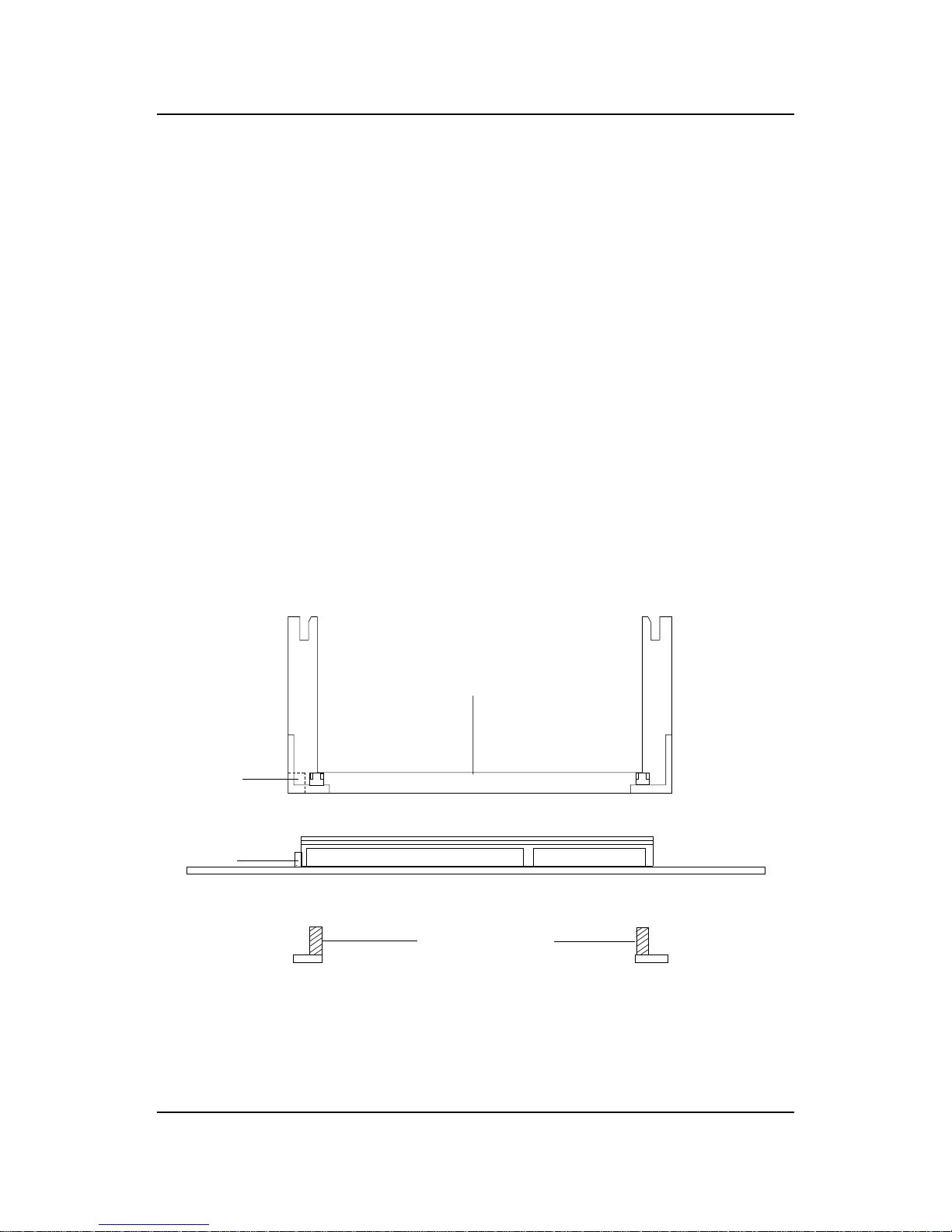
2-5
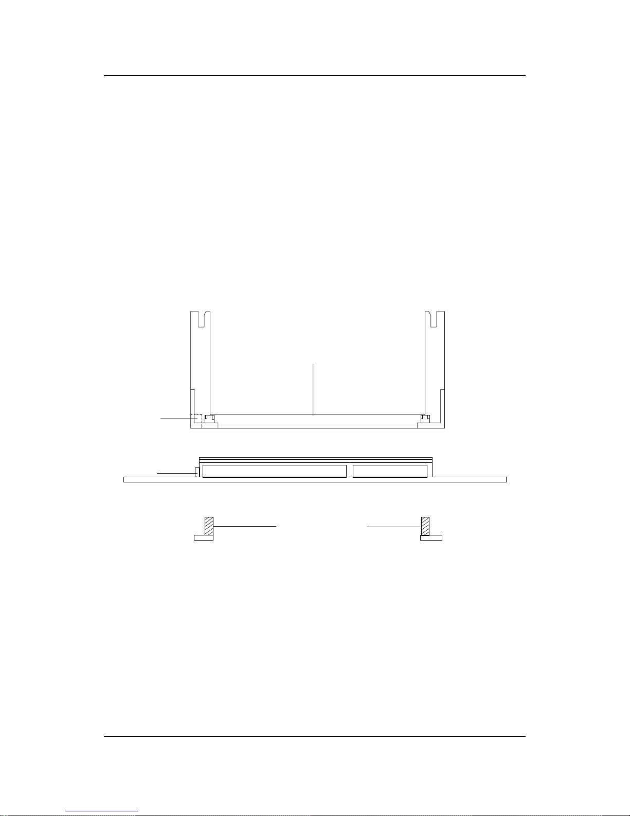
Step 3: Install the Heat Sink Support Base.
Look for the T wo holes across Slot 1, and match it with the Two legs
of the Heat Sink Support Base for the proper direction. T ake note
that one hole/leg is bigger than the other. The Four top pins of the
Heat Sink Support Base should also be oriented towards Slot 1.
Push the Heat Sink Support Base onto the mainboard, until you hear
a click sound. Check for a perfect fit.
Step 4: Install the Heat Sink Support Pin.
Push the Heat Sink Support Pins onto the two holes of the Heat Sink
Support Base. Check for a perfect fit. These pins are used to secure
the Heat Sink Support Base.
Heat Sink
Support Base
Heat Sink
Support Pin
Leg
pins
CHAPTER 2 HARDWARE INSTALLATION
2-6
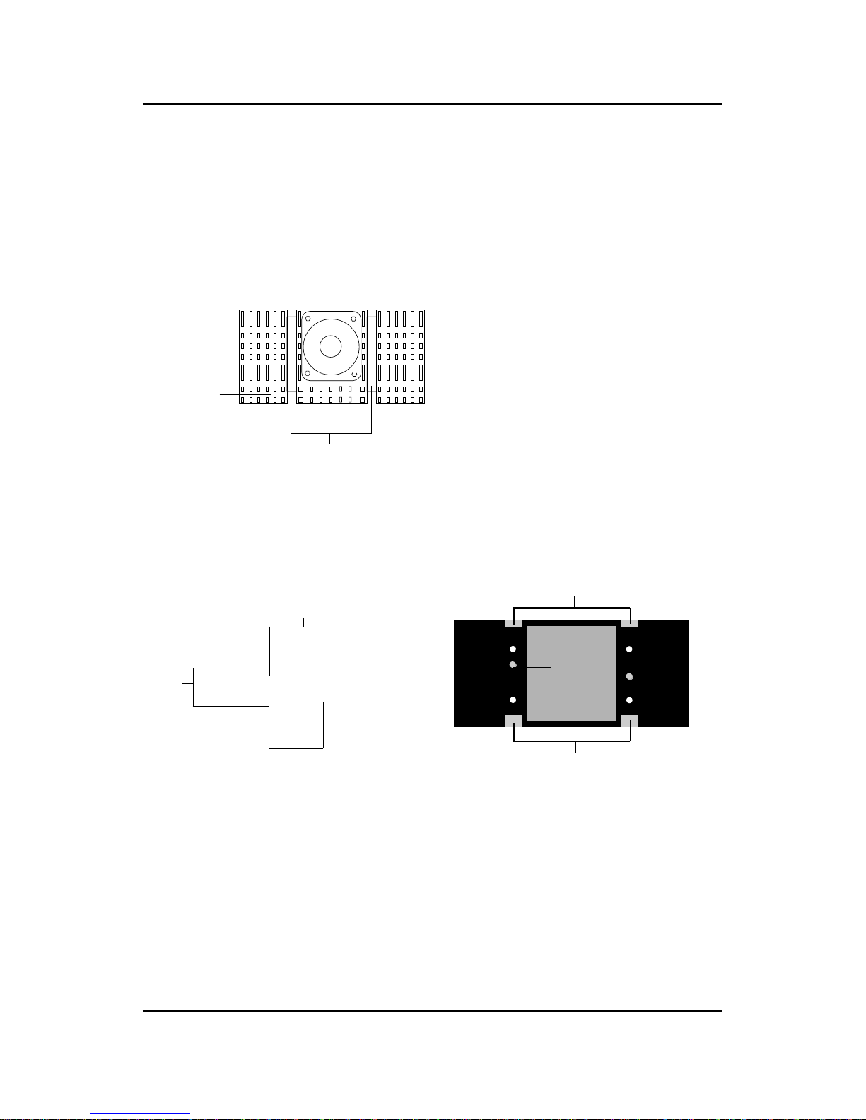
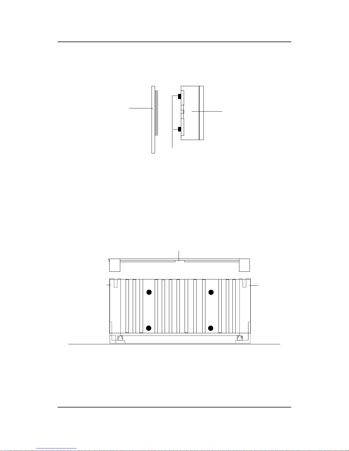
Step 5: Install the Heat Sink with Fan to the Processor .
Push down the metal clips, so that they are in line with the back of
the Heat Sink. Be careful, so as not detach the metal clips from the
Heat Sink.
In case the metal clips are detached from the Heat Sink, re-attach
them. Look for the arrow on the metal clip. This arrow should be
pointing down and aligned with the Heat Sink Support Base Holder.
Attach the Heat Sink to the processor.
- Look at the back of the Heat Sink and take note of the 2 secure
posts. Insert these 2 Secure posts to the 2 secure holes on the
back of the processor.
- Align the ears of the metal clips with the clip holders on the back of
the processor. Use a screw driver to push the metal clips onto the
clip holders. Check for a perfect fit.
Pentium® II processor (Back)
â
The arrow
should be
pointing
down.
Metal Clips
Heat Sink w/ Fan
Metal Clips Ear
Metal Clips Ear
Secure
Posts
Heat Sink w/ Fan(Back)
Heat Sink
Base Holder
Secure
holes
Clip Holder
Clip Holder

CHAPTER 2 HARDWARE INSTALLATION
2-7
Step 6: Install the Processor .
Unlock the Processor by pushing in the Processor Locks.
Insert the Processor like inserting a PCI or an ISA card.
Step 7: Lock the Processor Locks.
Secure the CPU by pulling the Processor Locks out.
è
ç
ç
è

CHAPTER 2 HARDWARE INSTALLATION
2-8
Step 8: Install the Heat Sink Support T op Bar .
Push the Heat Sink Support T op Bar to the Heat Sink Support Base,
Until you hear a “click” sound. Check for a perfect fit.
The installation is now complete.
Heatsink
Support Top
Bar
CHAPTER 2 HARDWARE INSTALLATION
2-9
B. Boxed Pentium® II/III processor Installation Procedures
The Boxed Pentium® II/III processor has a built- in Fan and Heat Sink. It also
has a Heat Sink Support. So if you’re going to use the Boxed processor, all
you need is the Retention Mechanism.
SLOT1
Retention
Mechanism
ê
ê
Key
êê
Retention
Mechanism
Attach Mount
Notch
Key
Step 1: Insert the Retention Mechanism Attach Mount at the bottom
of the mainboard.
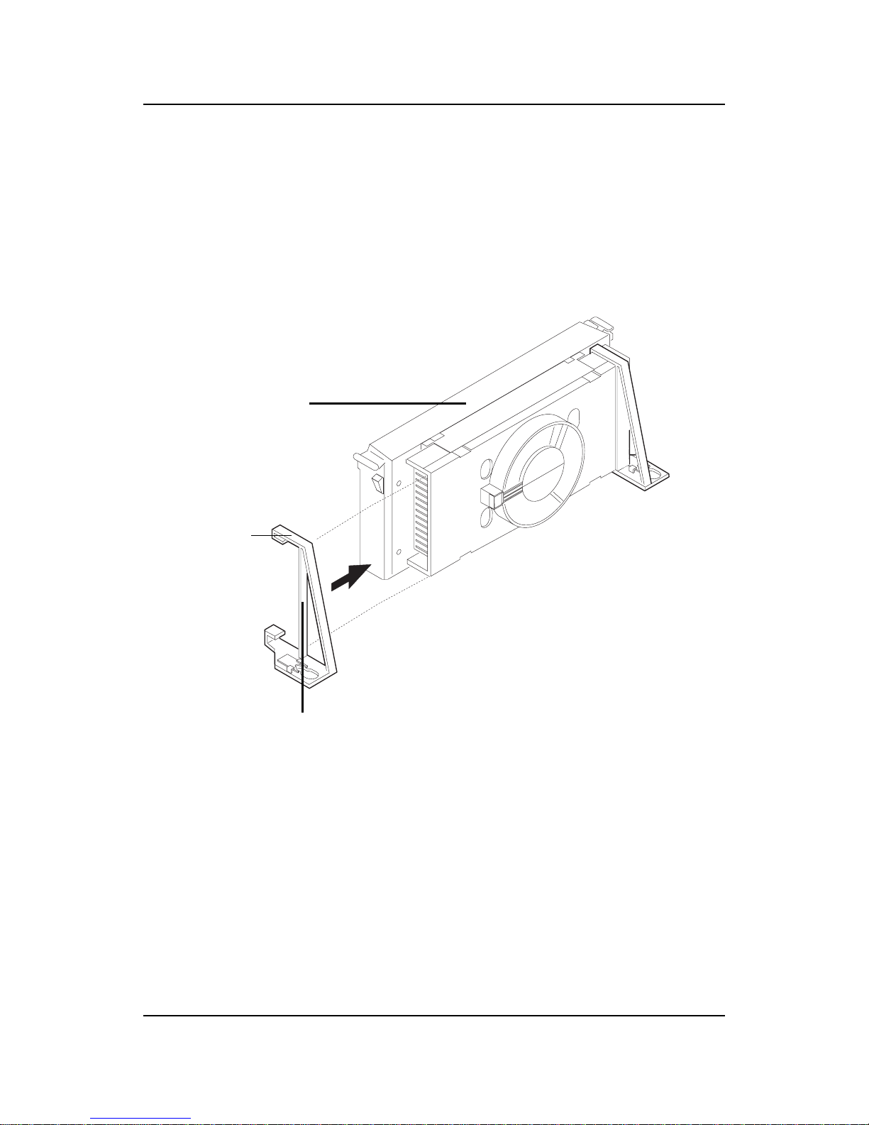
Step 2: Install the Retention Mechanism.
Look for the key on Slot 1, and match it with the Notch Key on the
Retention Mechanism for proper direction. Then, attach the
Retention Mechanism to the Retention Mechanism Attach Mount.
Use a Screwdriver to secure the Retention Mechanism.
CHAPTER 2 HARDWARE INSTALLATION
2-10
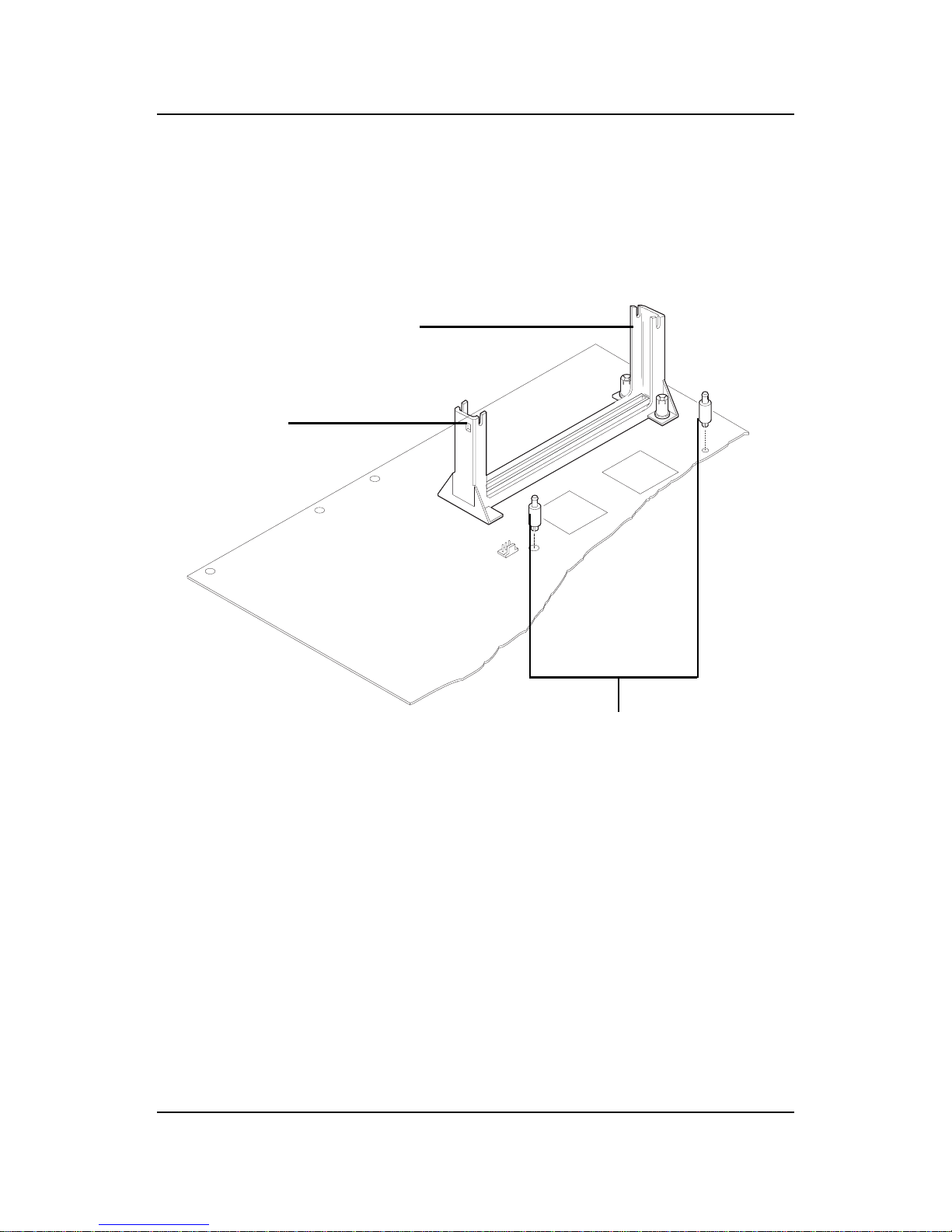
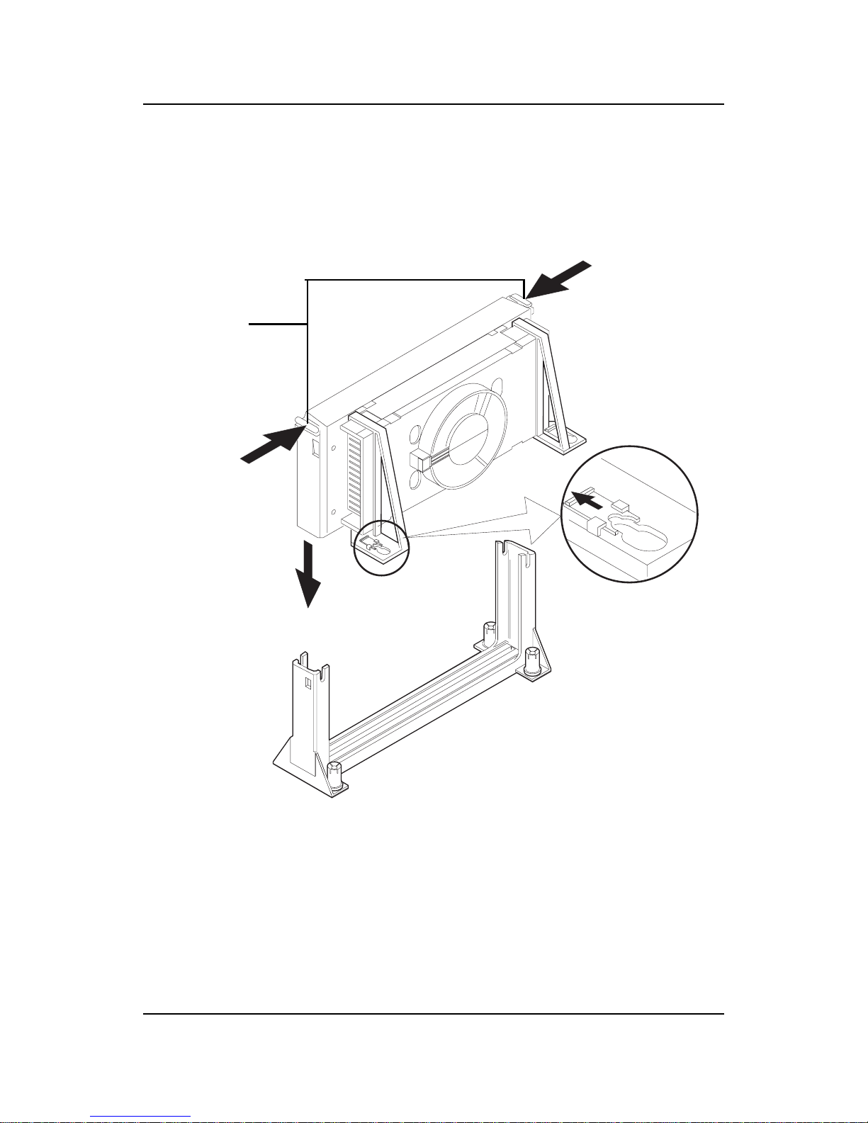
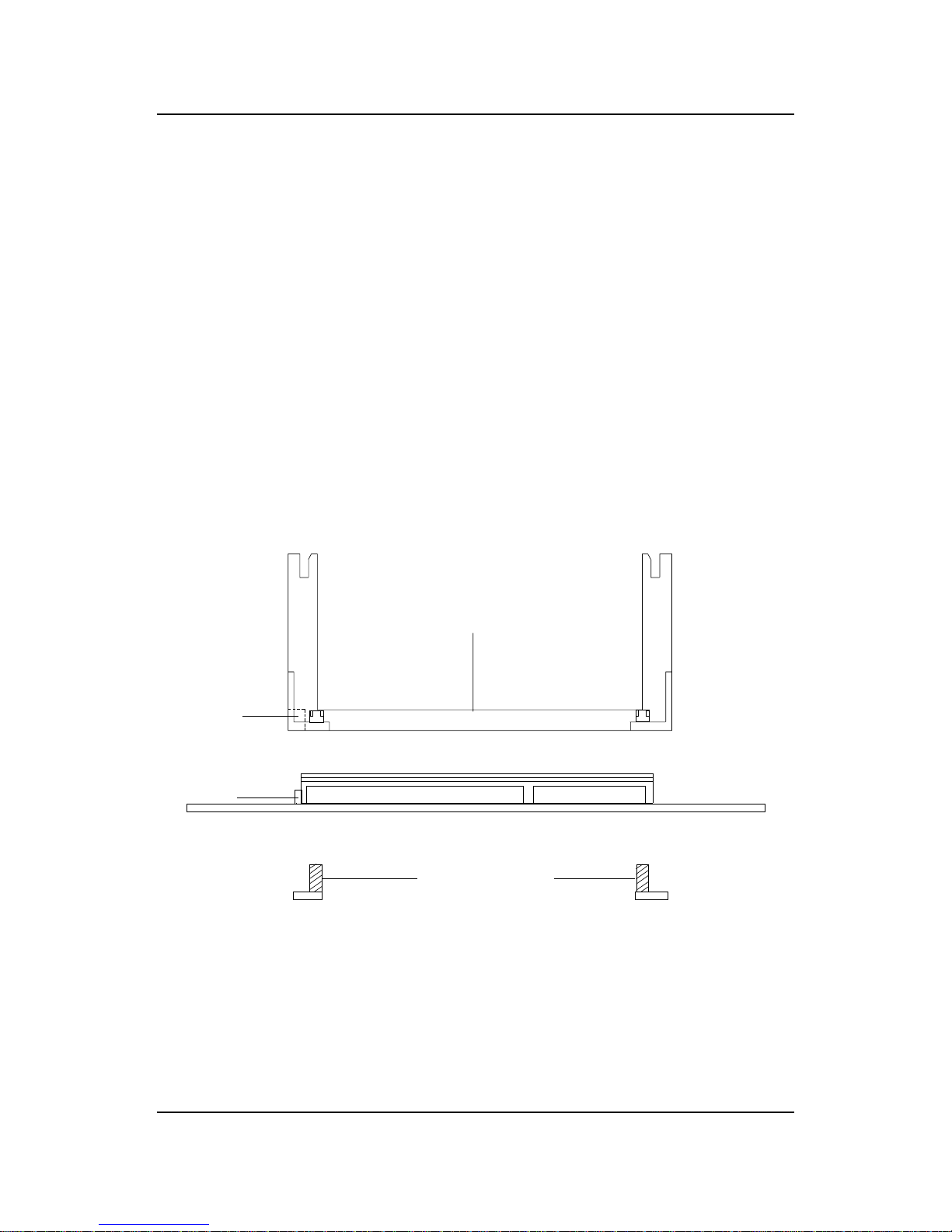
Step 3: Install the Heat Sink Support Base.
Look for the 2 holes across Slot 1, and match it with the 2 Heat Sink
Support Base. Take note that one hole/base is bigger than the other.
Push the Heat Sink Support Base onto the mainboard, until you hear
a click sound. Check for a perfect fit.
Retention
Mechanism
Notch
Hole
Heat Sink
Support Base
CHAPTER 2 HARDWARE INSTALLATION
2-11
PC-3743
Heat Sink
Support Lock
Intel® Boxed
PentiumTM II
Processor
Step 4: Install the Heat Sink Support.
Attach the 2 Heat Sink Supports to the sides of the Processor. These
Heat Sink Supports will fit in any direction, so be sure that the Heat
Sink Support Locks are oriented outwards for the proper direction.
Heat Sink
Support
CHAPTER 2 HARDWARE INSTALLATION
2-12
PC-3744
Processor
Lock
Heatsink
Support
Lock
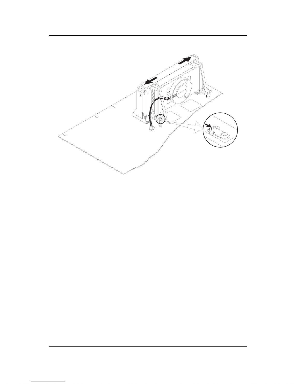
Step 5: Unlock the Processor Locks and Heat Sink Support Locks.
Push in the Processor Locks. Open the Heat Sink Support Locks.
Step 6: Insert the Processor like inserting a PCI or an ISA card.
CHAPTER 2 HARDWARE INSTALLATION
2-13
Step 7: Lock the Processor Locks and Heat Sink Support Locks
Secure the CPU by pushing out the Processor Locks. Close the Heat
Sink Support Locks.
The installation is now complete.
CHAPTER 2 HARDWARE INSTALLATION
2-14
SLOT1
Retention
Mechanism
ê
ê
Key
êê
Retention
Mechanism
Attach Mount
Notch
Key
Step 1: Insert the Retention Mechanism Attach Mount at the bottom
of the mainboard.
Step 2: Install the Retention Mechanism.
Look for the key on Slot 1, and match it with the Notch Key on the
Retention Mechanism for proper direction. Then, attach the Retention Mechanism to the Retention Mechanism Attach Mount. Use a
Screwdriver to secure the Retention Mechanism.
C. OEM CeleronTM Processor and Pentium II (S.E.C.C. 2)
processor Installation Procedures
CHAPTER 2 HARDWARE INSTALLATION
2-15
Step 3: Install the MSI Heat Sink (optional) to the Processor .
Push down the plastic clips, so that they are in line with the hole on
the processor . Check for perfect fit.
Step 4: Install the Processor .
Insert the Processor like inserting a PCI or an ISA card.
Step 5: Lock the Processor .
Lock the processor by putting the MSI Retention Cap provided. The
MSI Retention Cap will only fit in one direction. The MSI Retention
Cap is only used with Intel® CeleronTM processor and Intel
®
Penitum® II processor (S.E.C.C. 2).
ê
Heat Sink
Celeron
TM
processor
ê
plastic Clip
The instruction procedure may
vary depending on the Heat Sink
that you’re using.
ê
MSI Retention Cap
Notch
Hole
Notch
Hole
ê
CHAPTER 2 HARDWARE INSTALLATION
2-16
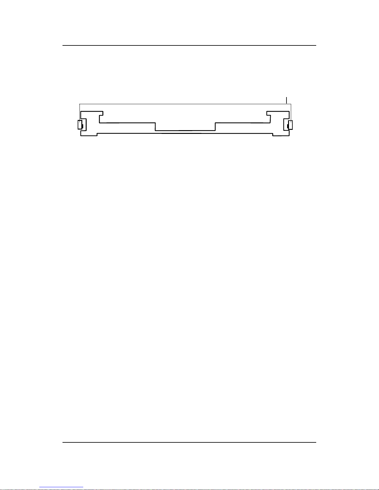
Procedure for detaching the MSI Retention Cap:
T o remove the Retention Cap.
- Pull the the Retention Cap Lock outward.
- Pull one side upward at a time.
MSI Retention Cap
(Top View)
Retention
Cap Lock
CHAPTER 2 HARDWARE INSTALLATION
2-17
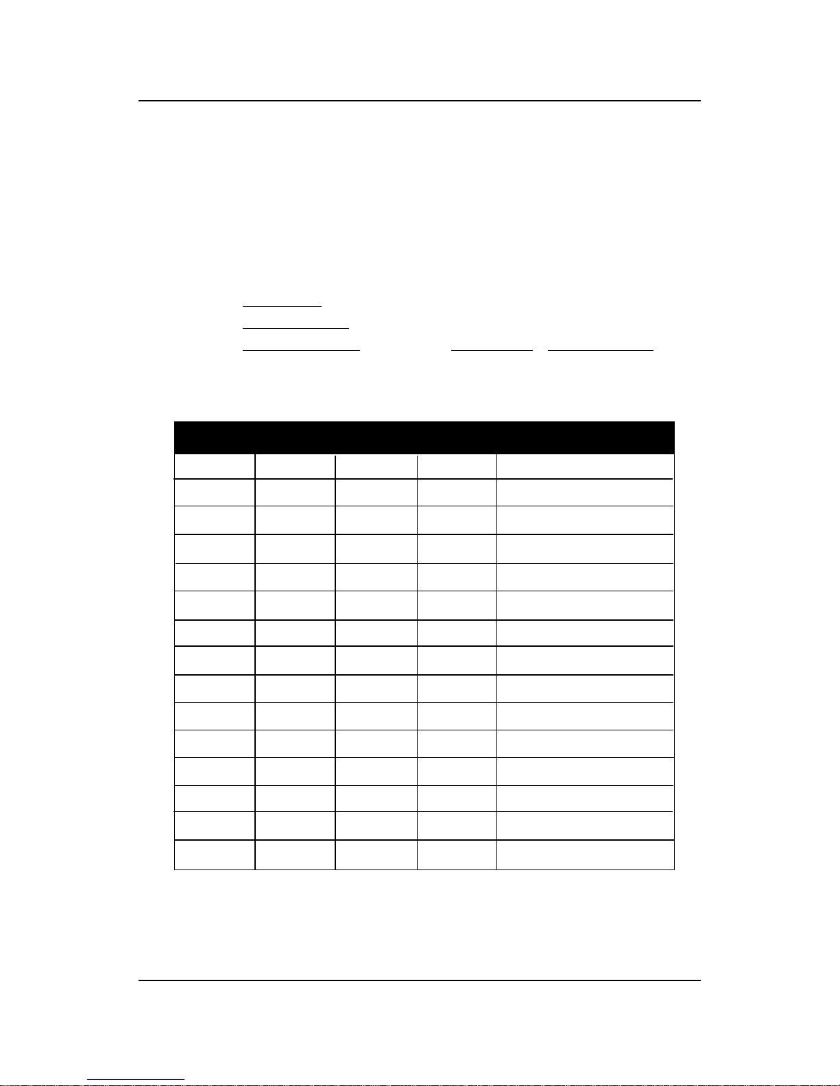
2.1-2 CPU Core Speed Derivation Procedure
1 2 3 4 Core/Bus Ratio
OFF OFF ON OFF 1 . 5
OFF OFF OFF OFF 2
ON OF F ON ON 2 .5
ON ON O FF ON 3
ON OFF OFF ON 3. 5
ON ON ON OFF 4
ON OFF ON OFF 4. 5
ON ON OFF OFF 5
ON OFF OFF OFF 5. 5
OFF ON ON ON 6
OFF OFF ON ON 6. 5
OFF ON OFF ON 7
OFF OFF OFF ON 7. 5
OFF ON ON OFF 8
1 . The DIP Switch SW1 (1, 2, 3, and 4) is used to set the Core/Bus (Fraction)
ratio of the CPU. The actual core speed of the CPU is the Host Clock
Frequency multiplied by the Core/Bus ratio. For example:
If CPU Clock = 66MHz/100MHz
Core/Bus ratio = 4
then CPU core speed = Host Clock x Core/Bus ratio
= 66MHz x 4/100MHz x 4
= 266MHz/400MHz
SW1
CPU
CHAPTER 2 HARDWARE INSTALLATION
2-18
2.1-3 CPU Speed Setting: SW1
To adjust the speed of the CPU, you must know the specifications of your
CPU (always ask the vendor for CPU spec.). The mainboard can auto-detect
between 66 or 100MHz CPU Bus Frequency .
Speed Setting
SW1
ON
OFF
1 2 3 4
ON
DIP
W ARNINGS
The ATI RAGE 128VR/RAGE PRO Turbo onboard graphics
controller should be disabled, when selecting over 100MHz
processor BUS speed. The onboard graphics controller
support only 66MHz/100MHz bus speed processor.
!
CHAPTER 2 HARDWARE INSTALLATION
2-19
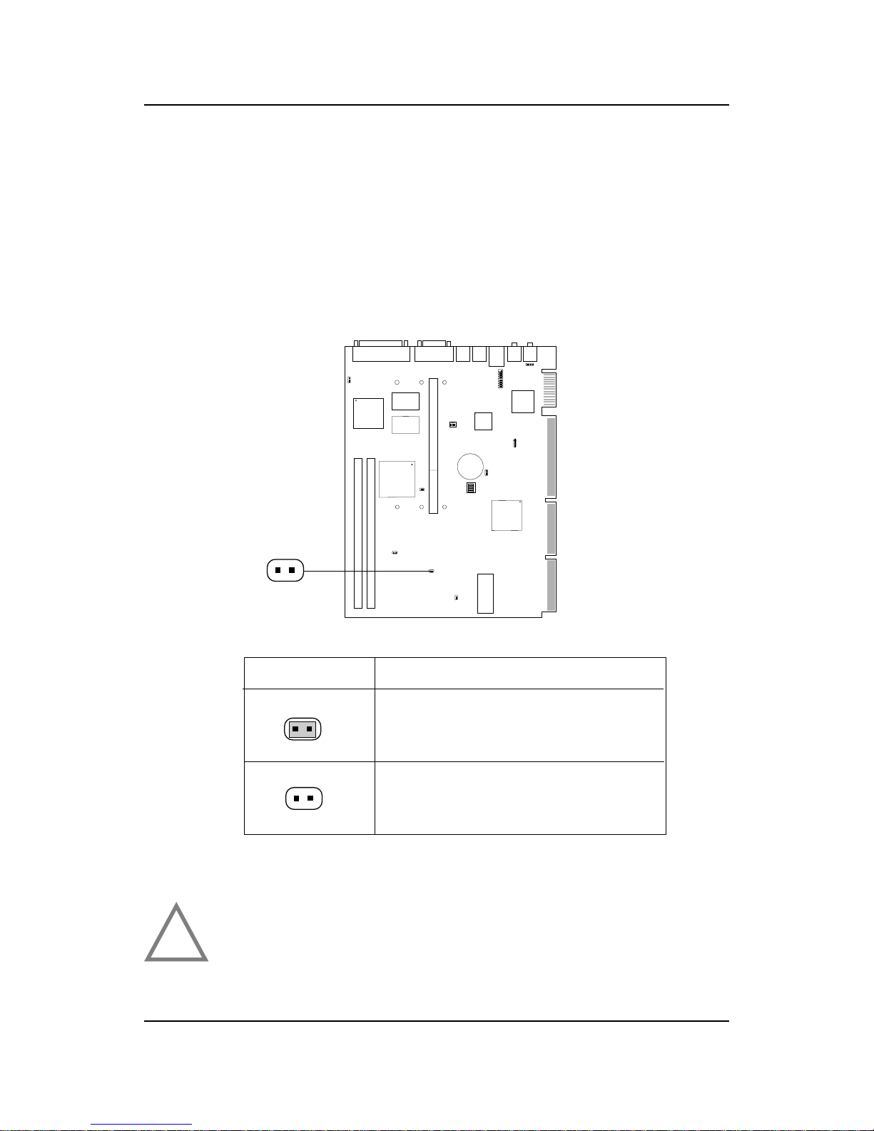
2.1-4 CPU Bus Frequency Selector: JK1
The JK1 jumper is used to set the CPU Bus Frequencies from 66MHz to
100MHz. When JK1 is shorted, this will automatically detect the CPU Bus
Frequency . When JK1 is open, if you used 66MHz CPU Bus Frequency, this
will set it V irtually into 100MHz.
JK1
Automatically detect 66MHz and
100MHz CPU Bus Frequency
JK1
Feature
Virtually set 66MHz CPU Bus
Frequency into 100MHz
WARNINGS
If you used the JK1 jumper to set the procesor bus frequency,
you need to disable the CPU Plug & Play feature on the BIOS.
!
CHAPTER 2 HARDWARE INSTALLATION
2-20
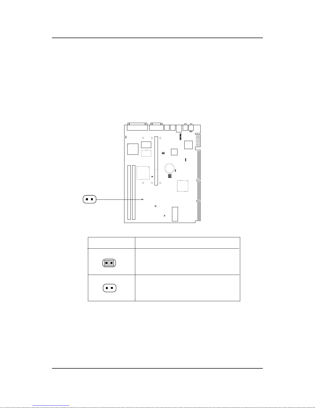
2.1-5 AGP Bus Frequency Selector: JK2
The JK2 jumper is used to set the AGP Bus Frequencies. When JK2 is
shorted, the AGP Bus Frequency will be set to 66MHz. When JK2 is open,
the AGP Bus Frequency will be the same with the CPU Bus Frequency .
JK2
66MHz AGP Bus Frequency
JK2
Feature
The AGP will have same Bus
Frequency with the processor
CHAPTER 2 HARDWARE INSTALLATION
2-21
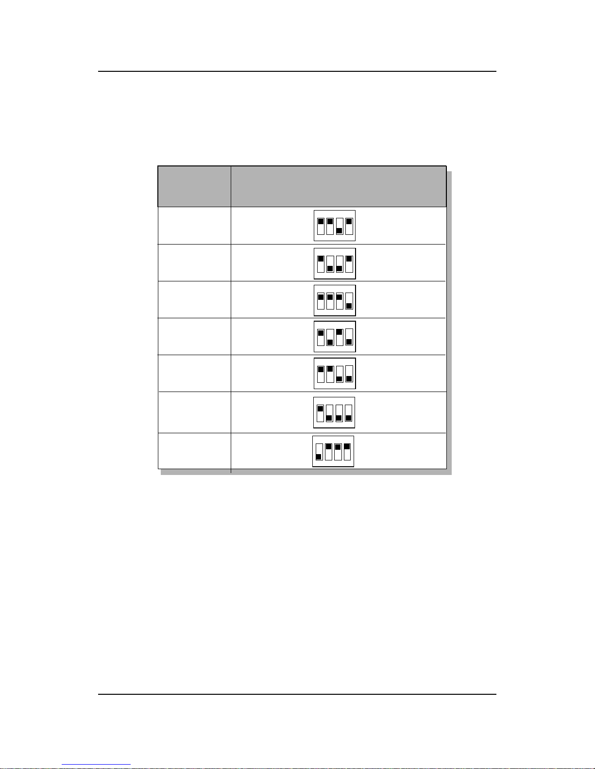
Table 2.1 200 ~ 333MHz Intel® Pentium® II/Celeron
TM
processor
233MHz
266MHz
300MHz
333MHz
200MHz
CPU
Type
SW1
ON
OFF
1 2 3 4
ON
DIP
ON
OFF
1 2 3 4
ON
DIP
ON
OFF
1 2 3 4
ON
DIP
ON
OFF
1 2 3 4
ON DIP
a. 66MHz CPU Bus Frequency
400MHz
433MHz
ON
OFF
1 2 3 4
ON DIP
ON
OFF
1 2 3 4
ON DIP
ON
OFF
1 2 3 4
ON
DIP
CHAPTER 2 HARDWARE INSTALLATION
2-22
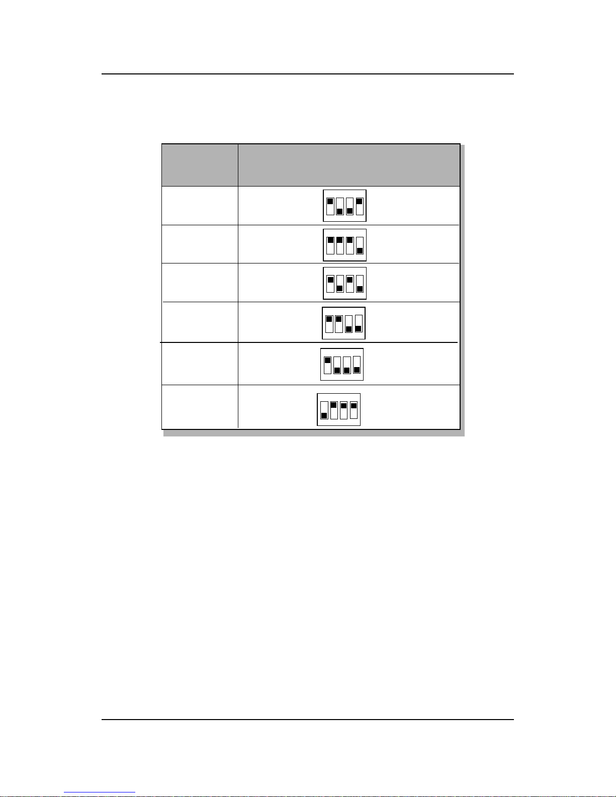
Table 2.2 350 ~ 450MHz Intel® Pentium® II processor
400MHz
450MHz
350MHz
CPU
Type
SW1
ON
OFF
1 2 3 4
ON DIP
ON
OFF
1 2 3 4
ON DIP
ON
OFF
1 2 3 4
ON
DIP
b. 100MHz CPU Bus Frequency
ON
OFF
1 2 3 4
ON
DIP
ON
OFF
1 2 3 4
ON
DIP
ON
OFF
1 2 3 4
ON
DIP
500MHz
550MHz
600MHz
CHAPTER 2 HARDWARE INSTALLATION
2-23
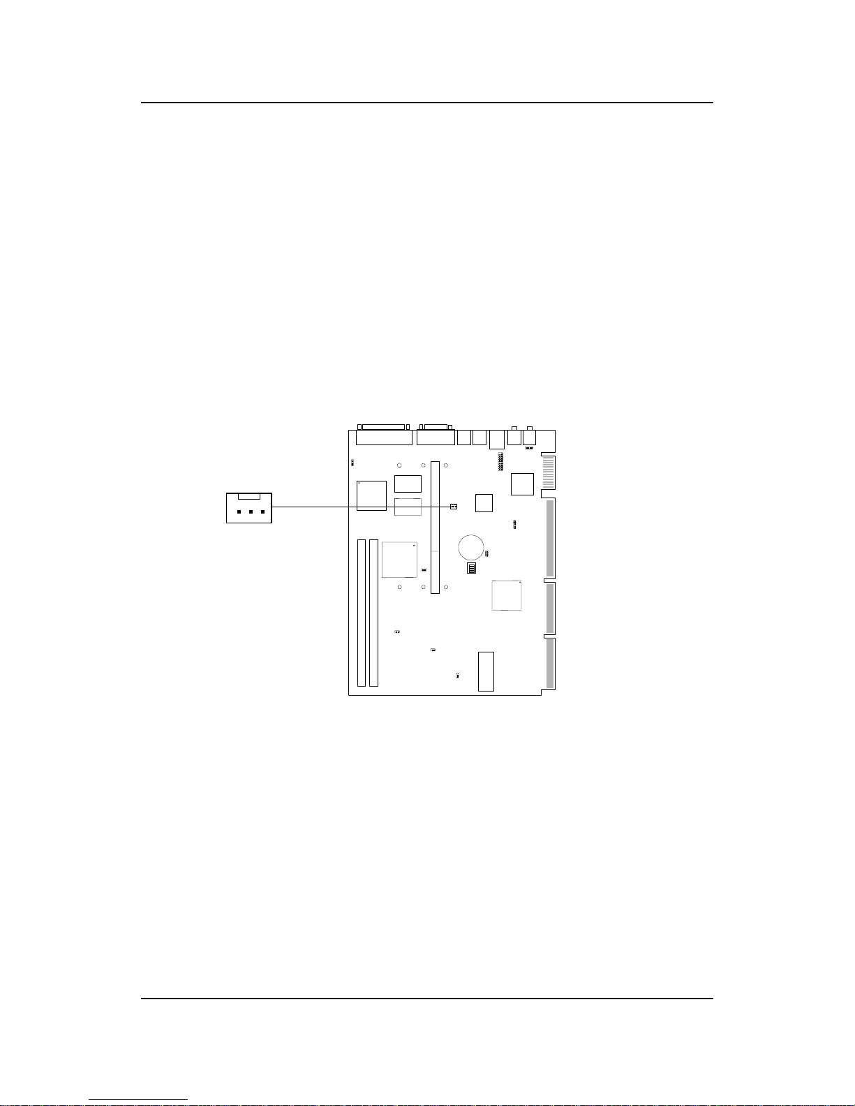
2.1-6 Fan Power Connector: CPUFAN
This connector support system cooling fan with +12V. It supports three pin
head connector. When connecting the wire to the connector, always take
note that the red wire is the positive and should be connected to the +12V,
the black wire is Ground and should be connected to GND. If your
mainboard had a System Hardware Monitor chipset on-board, you must use
a specially designed fan with speed sensor to take advantage of the CPU fan
control.
Note: For fans with speed sensor , every rotation of the fan will send out 2
pulses. System Hardware monitor will count and report the fan
rotation speed.
SENSOR
+12V
GND
CPUFAN
 Loading...