

Page 1

Quick Start
Thank you for purchasing the MSI® MAG Z390 TOMAHAWK
motherboard. This Quick Start section provides demonstration
diagrams about how to install your computer. Some of the
installations also provide video demonstrations. Please link to the
URL to watch it with the web browser on your phone or tablet. You
may have even link to the URL by scanning the QR code.
Kurzanleitung
Danke, dass Sie das MSI® MAG Z390 TOMAHAWK Motherboard
gewählt haben. Dieser Abschnitt der Kurzanleitung bietet eine Demo
zur Installation Ihres Computers. Manche Installationen bieten
auch die Videodemonstrationen. Klicken Sie auf die URL, um diese
Videoanleitung mit Ihrem Browser auf Ihrem Handy oder Table
anzusehen. Oder scannen Sie auch den QR Code mit Ihrem Handy,
um die URL zu öffnen.
Présentation rapide
Merci d’avoir choisi la carte mère MSI® MAG Z390 TOMAHAWK.
Ce manuel fournit une rapide présentation avec des illustrations
explicatives qui vous aideront à assembler votre ordinateur. Des
tutoriels vidéo sont disponibles pour certaines étapes. Cliquez sur
le lien fourni pour regarder la vidéo sur votre téléphone ou votre
tablette. Vous pouvez également accéder au lien en scannant le QR
code qui lui est associé.
Быстрый старт
Благодарим вас за покупку материнской платы MSI® MAG
Z390 TOMAHAWK. В этом разделе представлена информация,
которая поможет вам при сборке комьютера. Для некоторых
этапов сборки имеются видеоинструкции. Для просмотра
видео, необходимо открыть соответствующую ссылку в
веб-браузере на вашем телефоне или планшете. Вы также
можете выполнить переход по ссылке, путем сканирования
QR-кода.
Quick Start
I
Page 2
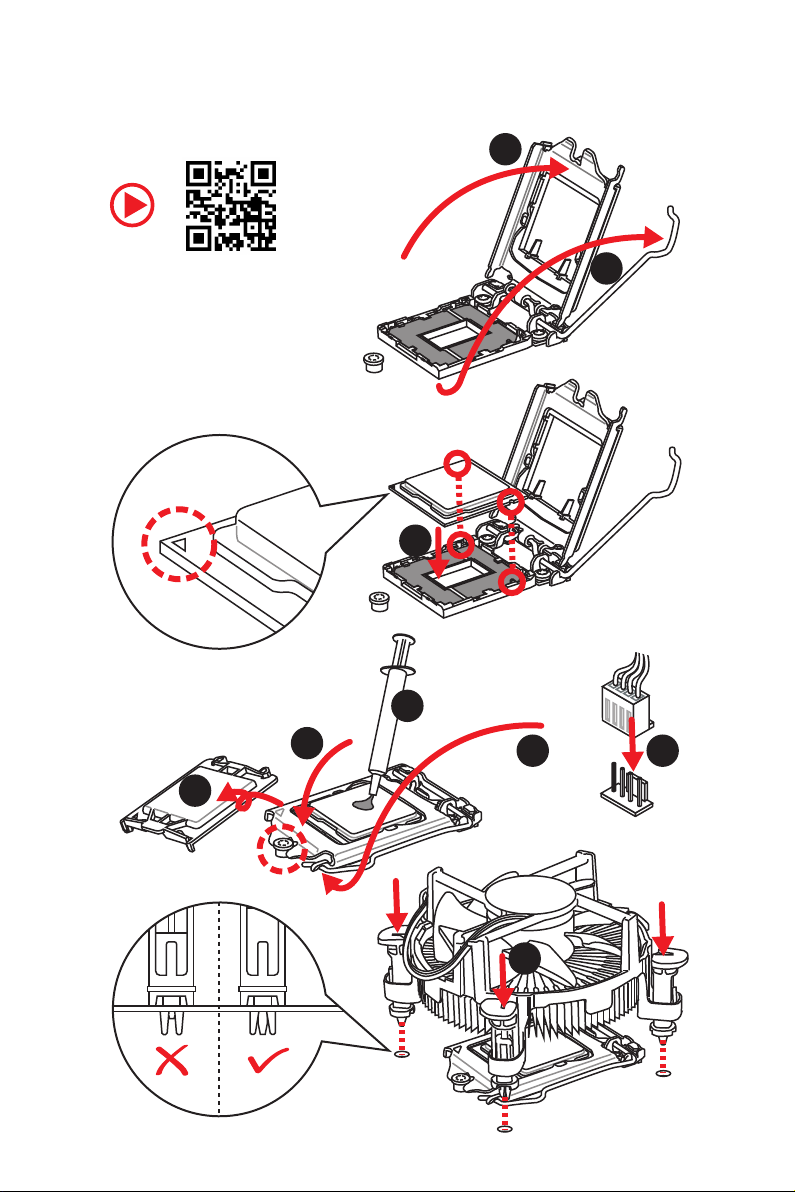
Installing a Processor/ Installation des Prozessors/ Installer un
processeur/ Установка процессора
2
https://youtu.be/4ce91YC3Oww
6
1
3
7
4
5
9
Quick Start
II
8
Page 3
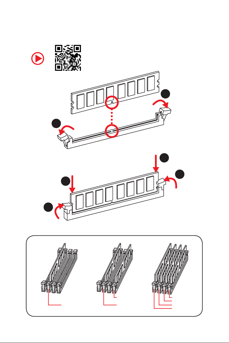
Installing DDR4 memory/ Installation des DDR4-Speichers/
Installer une mémoire DDR4/ Установка памяти DDR4
http://youtu.be/T03aDrJPyQs
1
1
2
3
2
3
DIMMB2 DIMMB2
DIMMA2 DIMMA2 DIMMA2
DIMMB1
DIMMA1
Quick Start
III
Page 4

RESET SW
POWER SW
POWER LED+
POWER LED-
HDD LED
Connecting the Front Panel Header/ Anschließen der
Frontpanel-Stiftleiste/ Connecter un connecteur du panneau
avant/ Подключение разъемов передней панели
http://youtu.be/DPELIdVNZUI
IV
2 10
1
Quick Start
JFP1
1 HDD LED + 2 Power LED +
3 HDD LED - 4 Power LED -
5 Reset Switch 6 Power Switch
9
7 Reset Switch 8 Power Switch
9 Reserved 10 No Pin
HDD LED
POWER LED
RESET SW
HDD LED
JFP1
HDD LED HDD LED +
POWER LED POWER LED +
Page 5
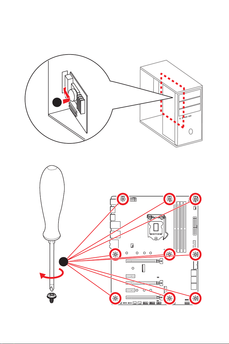
Installing the Motherboard/ Installation des Motherboards/
Installer la carte mère/ Установка материнской платы
1
2
Quick Start
V
Page 6
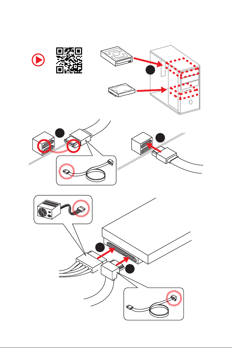
Installing SATA Drives/ Installation der SATA-Laufwerke/
Installer le disque dur SATA/ Установка дисков SATA
1
http://youtu.be/RZsMpqxythc
2
3
5
4
VI
Quick Start
Page 7
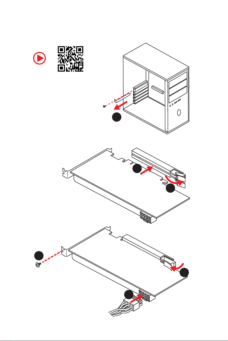
Installing a Graphics Card/ Einbau der Grafikkarte/ Installer
une carte graphique/ Установка дискретной видеокарты
http://youtu.be/mG0GZpr9w_A
1
3
2
5
4
6
Quick Start
VII
Page 8
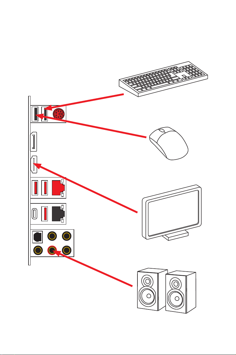
Connecting Peripheral Devices/ Peripheriegeräte/
Connecter un périphérique anschliessen/ Подключение
периферийных устройств
VIII
Quick Start
Page 9
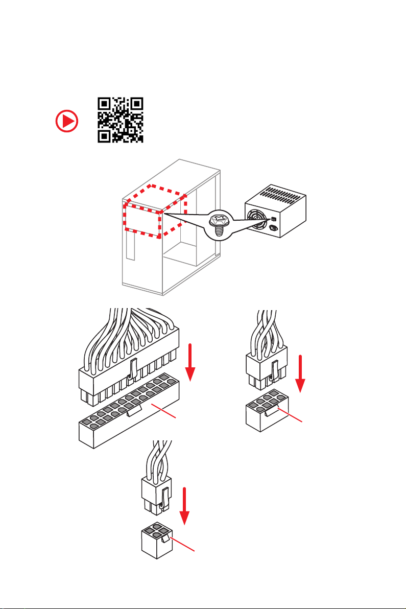
Connecting the Power Connectors/ Stromanschlüsse
anschliessen/ Connecter les câbles du module d’alimentation/
Подключение разъемов питания
http://youtu.be/gkDYyR_83I4
ATX_PWR1
CPU_PWR2
CPU_PWR1
Quick Start
IX
Page 10
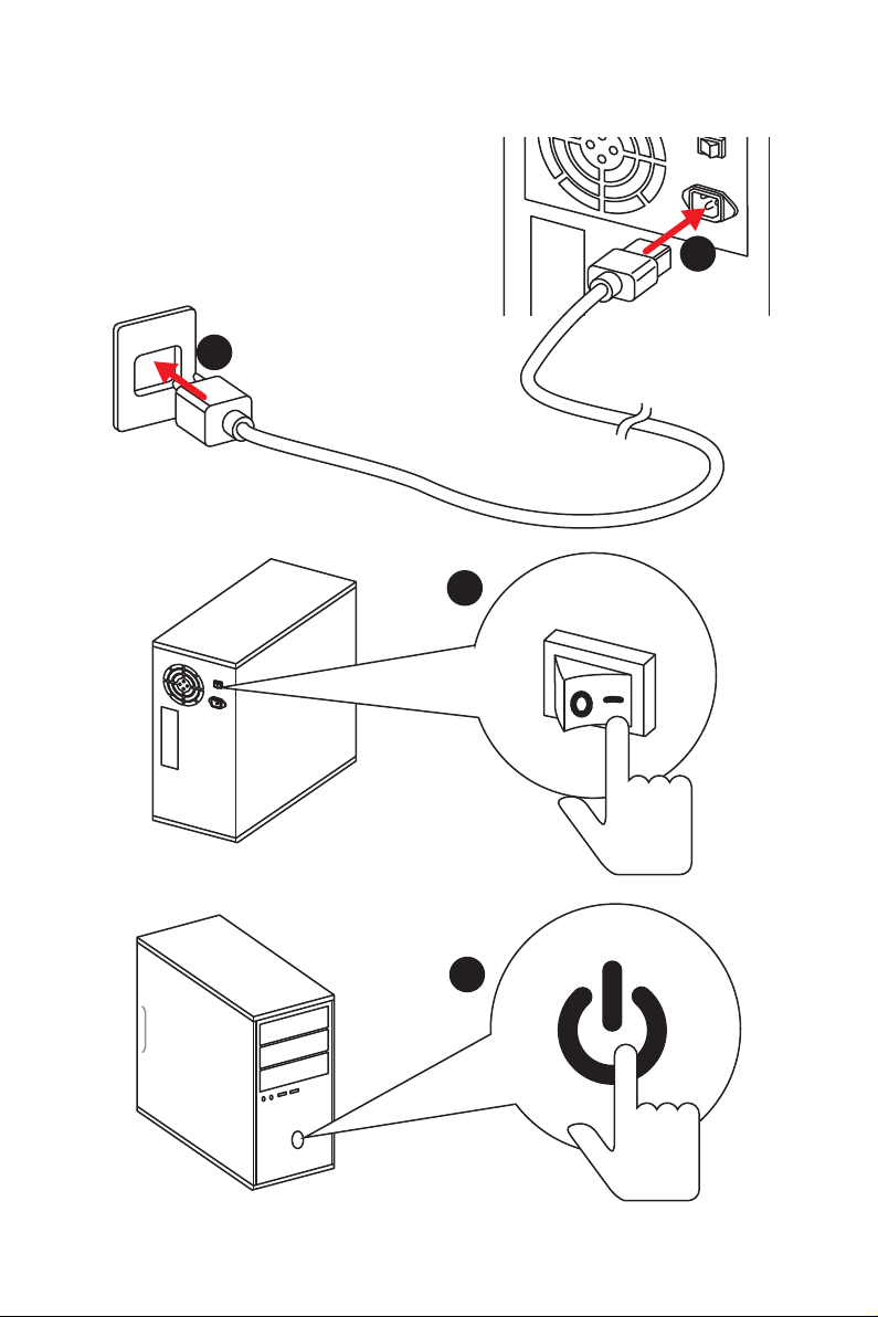
Power On/ Einschalten/ Mettre sous-tension/ Включение
питания
1
2
3
Quick Start
X
4
Page 11

Contents
Safety Information ................................................................................................. 2
Specifications ......................................................................................................... 3
Package contents .................................................................................................. 8
Rear I/O Panel ....................................................................................................... 9
LAN Port LED Status Table..................................................................................... 9
Audio Ports Configuration ...................................................................................... 9
Realtek Audio Console ......................................................................................... 10
Overview of Components .................................................................................... 12
CPU Socket ........................................................................................................... 13
DIMM Slots ............................................................................................................ 14
PCI_E1~5: PCIe Expansion Slots .......................................................................... 15
M2_1~2: M.2 Slots (Key M) ................................................................................... 16
SATA1~6: SATA 6Gb/s Connectors ....................................................................... 17
CPU_PWR1~2, ATX_PWR1: Power Connectors ................................................... 19
JFP1, JFP2: Front Panel Connectors ................................................................... 20
JAUD1: Front Audio Connector ............................................................................20
JUSB3~4: USB 3.1 Gen1 Connectors ................................................................... 21
JUSB1~2: USB 2.0 Connectors ............................................................................. 21
CPU_FAN1, PUMP_FAN1, SYS_FAN1~5: Fan Connectors ................................... 22
JCOM1: Serial Port Connector ............................................................................. 23
JCI1: Chassis Intrusion Connector ....................................................................... 23
JTPM1: TPM Module Connector ........................................................................... 24
JBAT1: Clear CMOS (Reset BIOS) Jumper ........................................................... 24
JRGB1~2, JRAINBOW1: RGB LED connectors ..................................................... 25
Onboard LEDs ...................................................................................................... 26
EZ Debug LED ....................................................................................................... 26
DIMM LEDs ........................................................................................................... 26
Installing OS, Drivers & Utilities ......................................................................... 27
Installing Windows® 10 ......................................................................................... 27
Installing Drivers .................................................................................................. 27
Installing Utilities ................................................................................................. 27
BIOS Setup ........................................................................................................... 28
Entering BIOS Setup ............................................................................................. 28
Resetting BIOS ...................................................................................................... 28
Updating BIOS ....................................................................................................... 29
EZ Mode ................................................................................................................ 30
Advanced Mode .................................................................................................... 32
OC Menu................................................................................................................ 33
Contents
1
Page 12

Safety Information
y The components included in this package are prone to damage from electrostatic
discharge (ESD). Please adhere to the following instructions to ensure successful
computer assembly.
y Ensure that all components are securely connected. Loose connections may cause
the computer to not recognize a component or fail to start.
y Hold the motherboard by the edges to avoid touching sensitive components.
y It is recommended to wear an electrostatic discharge (ESD) wrist strap when
handling the motherboard to prevent electrostatic damage. If an ESD wrist strap is
not available, discharge yourself of static electricity by touching another metal object
before handling the motherboard.
y Store the motherboard in an electrostatic shielding container or on an anti-static pad
whenever the motherboard is not installed.
y Before turning on the computer, ensure that there are no loose screws or metal
components on the motherboard or anywhere within the computer case.
y Do not boot the computer before installation is completed. This could cause
permanent damage to the components as well as injury to the user.
y If you need help during any installation step, please consult a certified computer
technician.
y Always turn off the power supply and unplug the power cord from the power outlet
before installing or removing any computer component.
y Keep this user guide for future reference.
y Keep this motherboard away from humidity.
y Make sure that your electrical outlet provides the same voltage as is indicated on the
PSU, before connecting the PSU to the electrical outlet.
y Place the power cord such a way that people can not step on it. Do not place anything
over the power cord.
y All cautions and warnings on the motherboard should be noted.
y If any of the following situations arises, get the motherboard checked by service
personnel:
Liquid has penetrated into the computer.
The motherboard has been exposed to moisture.
The motherboard does not work well or you can not get it work according to user
guide.
The motherboard has been dropped and damaged.
The motherboard has obvious sign of breakage.
y Do not leave this motherboard in an environment above 60°C (140°F), it may damage
the motherboard.
Safety Information
2
Page 13

Specifications
Supports Intel
CPU
Core™ / Pentium
socket
* Please go to www.intel.com for more compatibility information.
Chipset Intel® Z390 Chipset
y 4x DDR4 memory slots, support up to 64GB*
y Supports DDR4 4400(OC)/ 4300(OC)/ 4266(OC)/ 4200(OC)/
4133(OC)/ 4000(OC)/ 3866(OC)/ 3733(OC)/ 3600(OC)/
3466(OC)/ 3400(OC)/ 3333(OC)/ 3300(OC)/ 3200(OC)/ 3000(OC)
Memory
/ 2800(OC)/ 2666/ 2400/ 2133 MHz*
y Supports Dual-Channel mode
y Supports non-ECC, un-buffered memory
y Supports Intel
* Please refer www.msi.com for more information on compatible memory.
y 3x PCIe 3.0 x16 slots (support x16/x4/x1 modes)
Expansion Slot
y 2x PCIe 3.0 x1 slots
y 1x M.2 slot (Key E) for an Intel
y 1x HDMI™ port 1.4, supports a maximum resolution of
Onboard Graphics
4096x2160@24Hz
y 1x DisplayPort port 1.2, supports a maximum resolution of
4096X2304@60Hz
®
Core™ 9000 Series family/ 8th Gen Intel®
®
Gold / Celeron® processors for LGA 1151
®
Extreme Memory Profile (XMP)
®
CNVi wireless module only
Multi-GPU y Supports 2-Way AMD
®
Z390 Chipset
Intel
y 6x SATA 6Gb/s ports*
y 2x M.2 slots (Key M)*
M2_1 supports up to PCIe 3.0 x4 and SATA 6Gb/s, 2242/
2260/ 2280/ 22110 storage devices
Storage
M2_2 Supports up to PCIe 3.0 x4 and SATA 6Gb/s, 2242/
2260/ 2280 storage devices
®
Intel
Optane™ Memory Ready
* M.2 slots and SATA ports share the bandwidth. Please refer to page 17 for
details.
** Before using Intel
updated the drivers and BIOS to the latest version from MSI website.
®
Optane™ memory modules, please ensure that you have
Continued on next page
®
CrossFire™ Technology
Specifications
3
Page 14

RAID
LAN
USB
Audio
Back Panel
Connectors
Continued from previous page
®
Z390 Chipset
Intel
y Supports RAID 0, RAID1, RAID 5 and RAID 10 for SATA
storage devices
y Supports RAID 0 and RAID 1 for M.2 PCIe storage devices
®
1x Intel
I219-V Gigabit LAN controller
®
1x Intel
I211-AT Gigabit LAN controller
®
y Intel
Z390 Chipset
4x USB 3.1 Gen2 (SuperSpeed USB 10Gbps) ports (1
Type-C and 3 Type-A ports on the back panel)
4x USB 3.1 Gen1 (SuperSpeed USB) ports available
through the internal USB connectors
6x USB 2.0 (High-speed USB) ports (2 Type-A ports on
the back panel, 4 ports available through the internal
USB connectors)
®
y Realtek
ALC892 Codec
7.1-Channel High Definition Audio
Supports S/PDIF output
y 1x PS/2 keyboard/ mouse combo port
y 2x USB 2.0 Type-A ports
y 1x DisplayPort port
y 1x HDMI™ port
y 2x LAN (RJ45) ports
y 3x USB 3.1 Gen2 Type-A ports
y 1x USB 3.1 Gen2 Type-C port
y 5x OFC audio jacks
y 1x Optical S/PDIF OUT connector
Specifications
4
Continued on next page
Page 15

Continued from previous page
y 1x 24-pin ATX main power connector
y 1x 8-pin ATX 12V power connector
y 1x 4-pin ATX 12V power connector
y 6x SATA 6Gb/s connectors
y 2x USB 3.1 Gen1 connectors (supports additional 4 USB 3.1
Gen1 ports)
y 2x USB 2.0 connectors (supports additional 4 USB 2.0
ports)
y 1x 4-pin CPU fan connector
Internal Connectors
Debug LED y 4x EZ Debug LED
y 1x 4-pin Water Pump connector
y 5x 4-pin system fan connectors
y 1x Serial port connector
y 1x Front panel audio connector
y 2x System panel connectors
y 1x Chassis Intrusion connector
y 1x TPM module connector
y 2x 4-pin RGB LED connectors
y 1x 3-pin RAINBOW LED connector
I/O Controller NUVOTON NCT6797 Controller Chip
y CPU/System temperature detection
Hardware Monitor
Form Factor
BIOS Features
y CPU/System fan speed detection
y CPU/System fan speed control
y ATX Form Factor
y 9.6 in. x 12 in. (24.3 cm x 30.4 cm)
y 1x 128 Mb flash
y UEFI AMI BIOS
y ACPI 6.1, SMBIOS 2.8
y Multi-language
Continued on next page
Specifications
5
Page 16
Software
Dragon Center
Features
Special Features
Continued from previous page
y Drivers
y DRAGON CENTER
y MYSTIC LIGHT
y Open Broadcaster Software (OBS)
y CPU-Z MSI GAMING
y MSI App Player (BlueStacks)
®
y Intel
Extreme Tuning Utility
y Google Chrome™, Google Toolbar, Google Drive
y Norton™ Internet Security Solution
y GAME OPTIMIZATION
y OC Performance
y Hardware Monitor
y Eyerest
y LAN Manager
y Live Update
Please refer to http://download.
msi.com/manual/mb/
DRAGONCENTER2.pdf for more
details.
y Audio
Audio Boost
y Network
GAMING LAN with Gaming LAN Manager
Intel CNVi Ready
y Storage
Twin Turbo M.2
y Cooling
Extended Heatsink Design
Pump Fan
GAMING Fan Control
Specifications
6
Continued on next page
Page 17

Special Features
Continued from previous page
y LED
Mystic Light
Mystic Light Extension (RGB)
Mystic Light Extension (RAINBOW)
Mystic light SYNC
EZ DEBUG LED
y Protection
PCI-E Steel Armor
M.2 Shield Frozr
Pre-installed IO shielding
y Performance
Multi GPU – CrossFire Technology
DDR4 Boost
Core Boost
USB with type A+C
INTEL Turbo USB 3.1 Gen 2
8-pin CPU Power
y VR
VR Ready
y Gamer Experience
GAMING HOTKEY
GAMING MOUSE Control
APP Player
y BIOS
Click BIOS 5
Specifications
7
Page 18
Package contents
Please check the contents of your motherboard package. It should contain:
Motherboard MAG Z390 TOMAHAWK
Cable
Accessories
Application DVD Driver DVD 1
Documentation
Important
If any of the above items are damaged or missing, please contact your retailer.
SATA 6Gb/s Cables 2
RGB LED Extension 80cm 1
M.2 Screw 1
Case Badge 1
VIP Card 1
User Manual 1
Quick Installation Guide 1
Package contents
8
Page 19
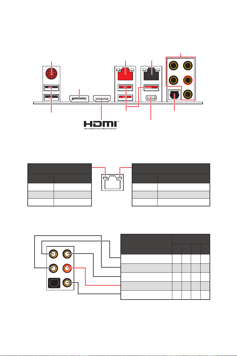
Rear I/O Panel
PS/2
DisplayPort
Audio Ports
LAN LAN
USB 2.0
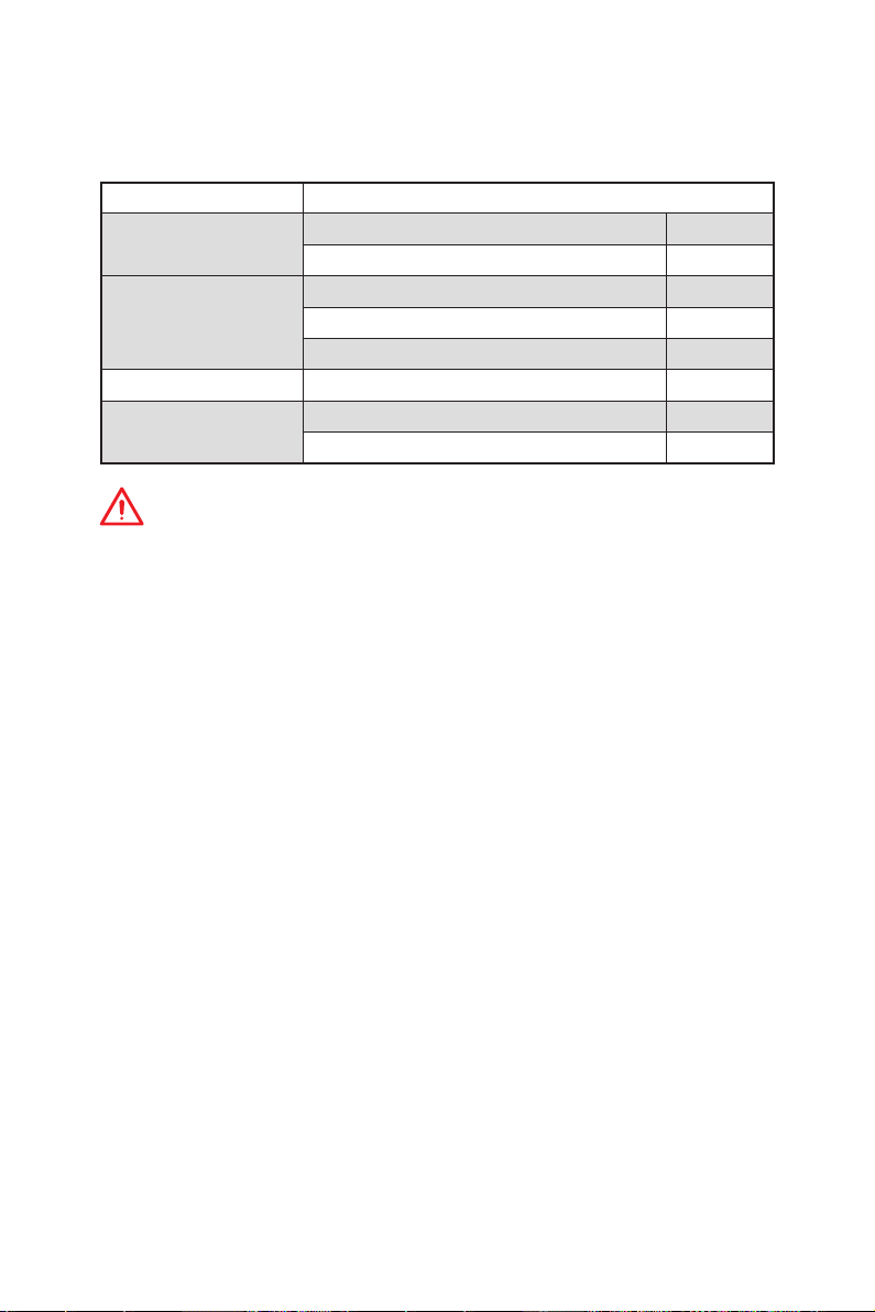
LAN Port LED Status Table
Link/ Activity LED
Status Description
Off No link
Yellow Linked
Blinking Data activity
Audio Ports Configuration
USB 3.1 Gen2
Optical S/PDIF-Out
USB 3.1 Gen2 Type-C
Speed LED
Status Description
Off 10 Mbps connection
Green 100 Mbps connection
Orange 1 Gbps connection
Audio Ports
2 4 6 8
Center/ Subwoofer Out ● ●
Rear Speaker Out ● ● ●
Line-In/ Side Speaker Out ●
Line-Out/ Front Speaker Out ● ● ● ●
Mic In
(●: connected, Blank: empty)
Channel
Rear I/O Panel
9
Page 20
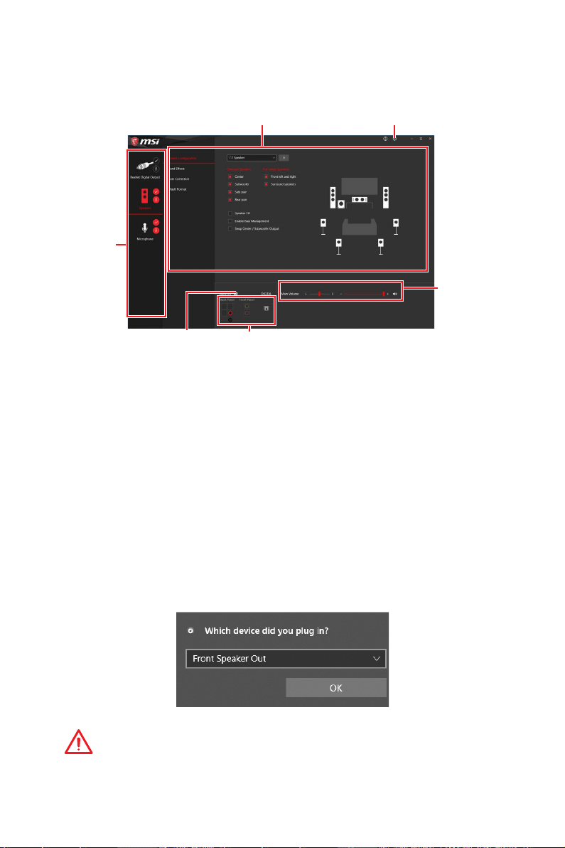
Realtek Audio Console
After Realtek Audio Console is installed. You can use it to change sound settings to get
better sound experience.
Device
Selection
Application Enhancement Advanced Settings
Main Volume
Connector Settings
Jack Status
y Device Selection - allows you to select a audio output source to change the related
options. The check sign indicates the devices as default.
y Application Enhancement - the array of options will provide you a complete guidance
of anticipated sound effect for both output and input device.
y Main Volume - controls the volume or balance the right/left side of the speakers that
you plugged in front or rear panel by adjust the bar.
y Advanced Settings - provides the mechanism to deal with 2 independent audio
streams.
y Jack Status - depicts all render and capture devices currently connected with your
computer.
y Connector Settings - configures the connection settings.
Auto popup dialog
When you plug into a device at an audio jack, a dialogue window will pop up asking you
which device is current connected.
Each jack corresponds to its default setting as shown on the next page.
Important
The pictures above for reference only and may vary from the product you purchased.
Rear I/O Panel
10
Page 21

Audio jacks to headphone and microphone diagram
Audio jacks to stereo speakers diagram
AUDIO INPUT
Audio jacks to 7.1-channel speakers diagram
AUDIO INPUT
Rear Front
Side Center/
Subwoofer
Rear I/O Panel
11
Page 22
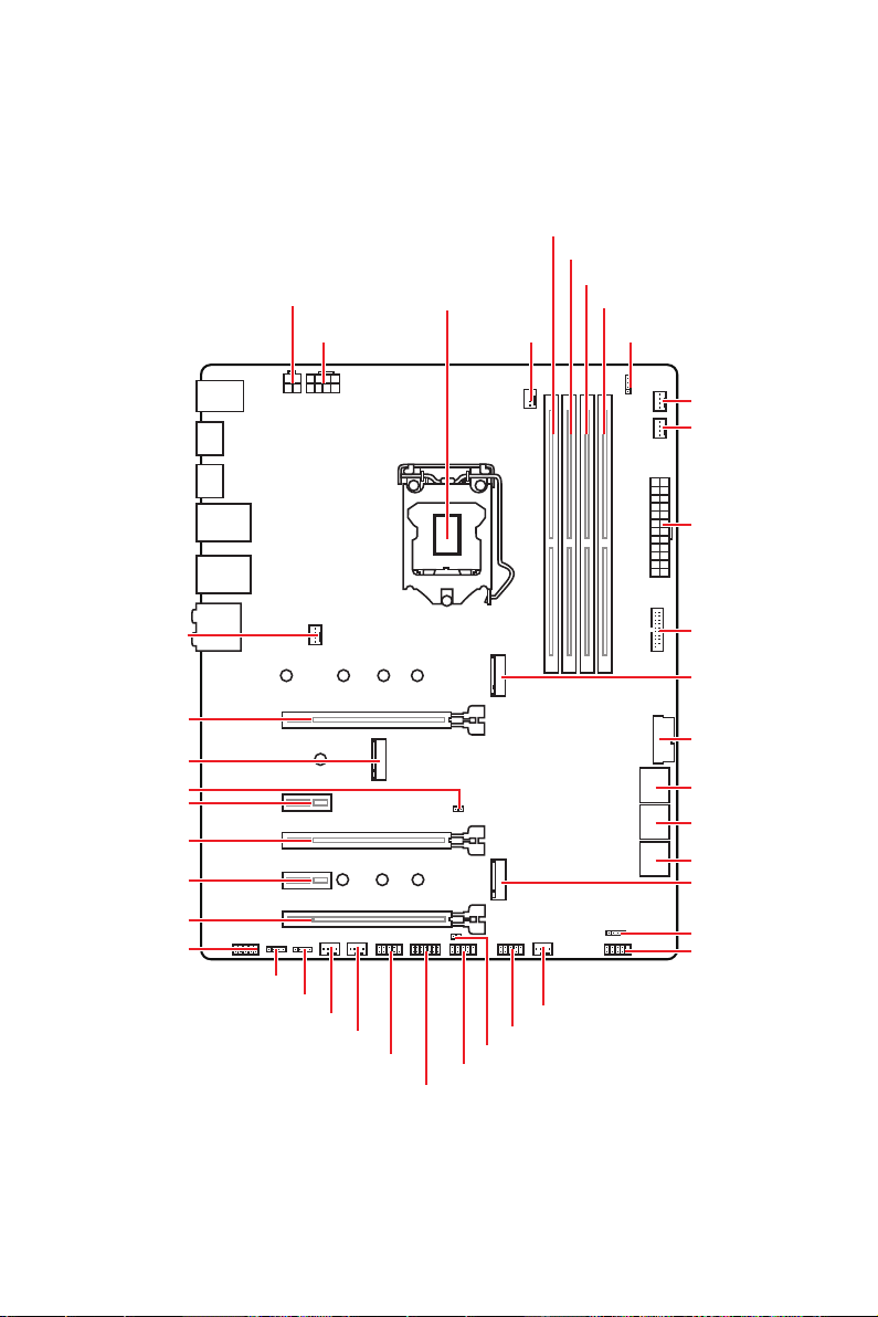
Overview of Components
CPU_PWR2
CPU_PWR1
CPU Socket
CPU_FAN1
DIMMA1
DIMMA2
DIMMB1
DIMMB2
JRGB2
PUMP_FAN1
SYS_FAN1
ATX_PWR1
SYS_FAN2
PCI_E1
CNVI_1
JBAT1
PCI_E2
PCI_E3
PCI_E4
PCI_E5
JAUD1
JRGB1
JRAINBOW1
SYS_FAN3
SYS_FAN4
JCOM1
JTPM1
JUSB1
JCI1
JUSB2
SYS_FAN5
JUSB3
M2_1
JUSB4
SATA▼1▲2
SATA▼3▲4
SATA▼5▲6
M2_2
JFP2
JFP1
Overview of Components
12
Page 23
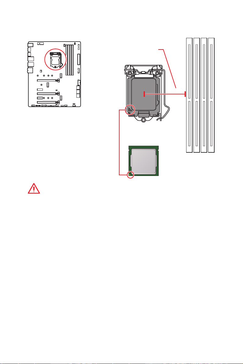
CPU Socket
Distance from the center of the
CPU to the nearest DIMM slot.
50.77 mm
Introduction to the LGA 1151 CPU
The surface of the LGA 1151 CPU has
two notches and a golden triangle to
assist in correctly lining up the CPU for
motherboard placement. The golden
triangle is the Pin 1 indicator.
Important
y
Always unplug the power cord from the power outlet before installing or removing
the CPU.
y
Please retain the CPU protective cap after installing the processor. MSI will deal with
Return Merchandise Authorization (RMA) requests if only the motherboard comes with
the protective cap on the CPU socket.
y
When installing a CPU, always remember to install a CPU heatsink. A CPU heatsink
is necessary to prevent overheating and maintain system stability.
y
Confirm that the CPU heatsink has formed a tight seal with the CPU before booting
your system.
y
Overheating can seriously damage the CPU and motherboard. Always make sure
the cooling fans work properly to protect the CPU from overheating. Be sure to apply
an even layer of thermal paste (or thermal tape) between the CPU and the heatsink to
enhance heat dissipation.
y
Whenever the CPU is not installed, always protect the CPU socket pins by covering
the socket with the plastic cap.
y
If you purchased a separate CPU and heatsink/ cooler, Please refer to the
documentation in the heatsink/ cooler package for more details about installation.
y
This motherboard is designed to support overclocking. Before attempting to
overclock, please make sure that all other system components can tolerate
overclocking. Any attempt to operate beyond product specifications is not
recommended. MSI
operation beyond product specifications.
®
does not guarantee the damages or risks caused by inadequate
Overview of Components
13
Page 24
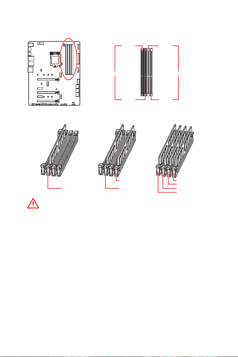
DIMM Slots
DIMMA1 DIMMB1
Channel A Channel B
DIMMA2 DIMMB2
Memory module installation recommendation
DIMMB2 DIMMB2
DIMMA2 DIMMA2 DIMMA2
DIMMB1
DIMMA1
Important
y
Always insert memory modules in the DIMMA2 slot first.
y
Due to chipset resource usage, the available capacity of memory will be a little less
than the amount of installed.
y
Based on Intel CPU specification, the Memory DIMM voltage below 1.35V is
suggested to protect the CPU.
y
Please note that the maximum capacity of addressable memory is 4GB or less
for 32-bit Windows OS due to the memory address limitation. Therefore, we
recommended that you to install 64-bit Windows OS if you want to install more than
4GB memory on the motherboard.
y
Some memory may operate at a lower frequency than the marked value when
overclocking due to the memory frequency operates dependent on its Serial Presence
Detect (SPD). Go to BIOS and find the Memory Try It! to set the memory frequency if
you want to operate the memory at the marked or at a higher frequency.
y
It is recommended to use a more efficient memory cooling system for full DIMMs
installation or overclocking.
y
The stability and compatibility of installed memory module depend on installed CPU
and devices when overclocking.
Overview of Components
14
Page 25
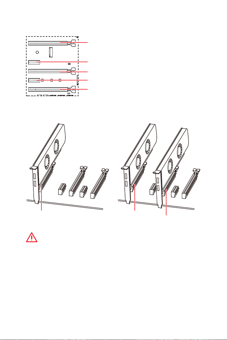
PCI_E1~5: PCIe Expansion Slots
PCI_E1: PCIe 3.0 x16 (CPU lanes)
PCI_E2: PCIe 3.0 x1 (PCH lanes)
PCI_E3: PCIe 3.0 x4 (PCH lanes)
PCI_E4: PCIe 3.0 x1 (PCH lanes)
PCI_E5: PCIe 3.0 x1 (PCH lanes)
Multiple graphics cards installation recommendation
x16 x16
x4
Important
y
If you install a large and heavy graphics card, you need to use a tool such as MSI
Gaming Series Graphics Card Bolster to support its weight to prevent deformation of
the slot.
y
For a single PCIe x16 expansion card installation with optimum performance, using
the PCI_E1 slot is recommended.
y
When adding or removing expansion cards, always turn off the power supply and
unplug the power supply power cable from the power outlet. Read the expansion
card’s documentation to check for any necessary additional hardware or software
changes.
Overview of Components
15
Page 26
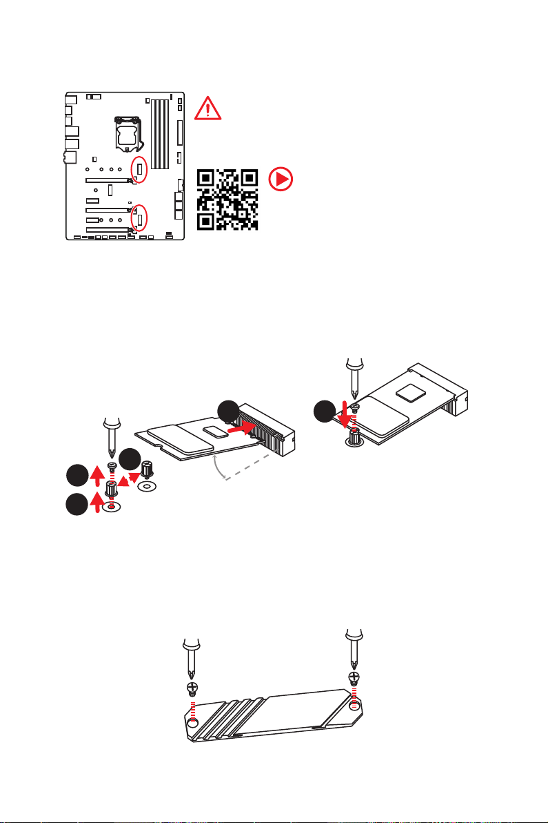
M2_1~2: M.2 Slots (Key M)
Important
y
Intel® RST only supports PCIe M.2 SSD with UEFI ROM.
y
Intel® Optane™ Memory Ready for all M.2 slots.
M2_1
M2_2
Video Demonstration
Watch the video to learn how to Install M.2
module.
http://youtu.be/JCTFABytrYA
Installing M.2 module
1. Remove the screw from the base screw.
2. Remove the base screw.
3. Tighten the base screw into the hole of
the distance to the M.2 slot as the length
your M.2 module.
4. Insert your M.2 module into the M.2 slot
at a 30-degree angle.
4
5. Put the screw in the notch on
the trailing edge of your M.2
module and tighten it into the
base screw.
5
3
1
30°
2
Using M.2 Shield Frozr
We provide the M.2 Shield Frozr on the M2_2 slot to help dissipate heat away from
the M.2 module. Before installing the M.2 module, you need to remove 2 screws that
secure the M.2 Shield Frozr, lift the M.2 Shield Frozr and remove the protective film
from the thermal pad.
Overview of Components
16
Page 27
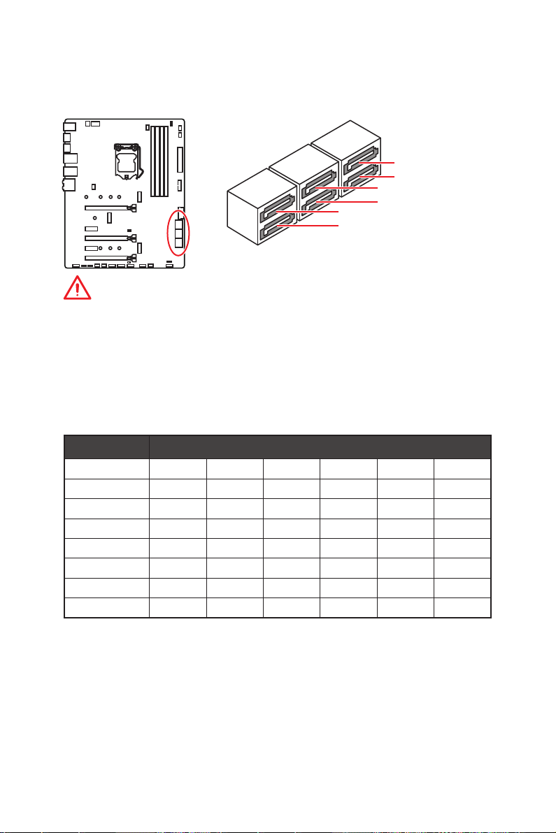
SATA1~6: SATA 6Gb/s Connectors
These connectors are SATA 6Gb/s interface ports. Each connector can connect to one
SATA device.
SATA2
SATA1
SATA4
SATA3
SATA6
SATA5
Important
y
Please do not fold the SATA cable at a 90-degree angle. Data loss may result during
transmission otherwise.
y
SATA cables have identical plugs on either sides of the cable. However, it is
recommended that the flat connector be connected to the motherboard for space
saving purposes.
M.2 & SATA combination table
Slot Available SATA connectors
M2_1 PCIe SATA PCIe SATA PCIe SATA
M2_2 PCIe PCIe SATA SATA ─ ─
SATA1 ✓ ✓ ✓ ✓ ✓ ✓
SATA2 ✓ ─ ✓ ─ ✓ ─
SATA3 ✓ ✓ ✓ ✓ ✓ ✓
SATA4 ✓ ✓ ✓ ✓ ✓ ✓
SATA5 ─ ─ ─ ─ ✓ ✓
SATA6 ─ ─ ─ ─ ✓ ✓
(SATA: M.2 SATA SSD, PCIe: M.2 PCIe SSD, ✓: available, ─: unavailable)
Overview of Components
17
Page 28
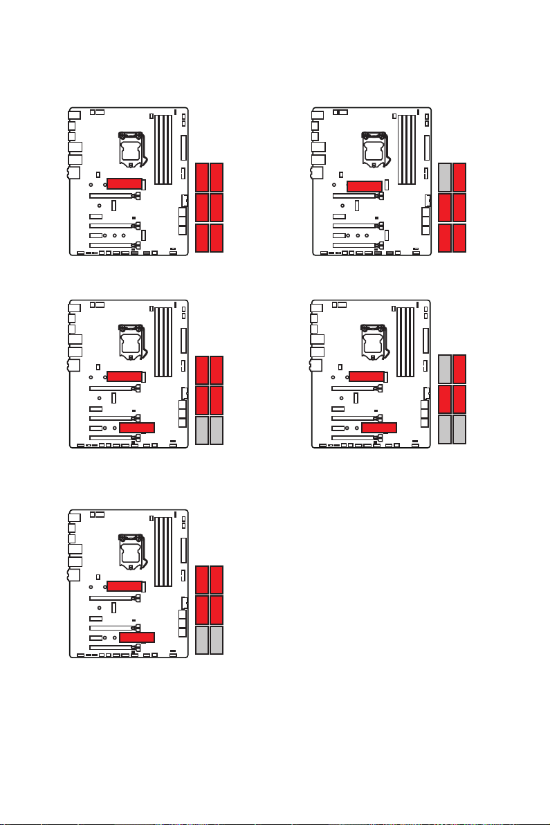
M.2 slots with examples of various combination possibilities
1xM.2 PCIe SSD + 6xSATA HDDs
M.2 PCIe
SATA2SATA2SATA2
SATA1SATA1SATA1
SATA4SATA4SATA4
SATA3SATA3SATA3
SATA6
SATA5
2xM.2 PCIe SSDs + 4xSATA HDDs
M.2 PCIe
M.2 PCIe
1xM.2 PCIe SSD + 1xM.2 SATA SSD +
4xSATA HDDs
1xM.2 SATA SSD + 5xSATA HDDs
M.2 SATA
SATA4SATA4
SATA6
2xM.2 SATA SSDs + 3xSATA HDDs
M.2 SATA
M.2 SATA
SATA3SATA3
SATA5
SATA1 SATA1
M.2 PCIe
Overview of Components
18
M.2 SATA
Page 29
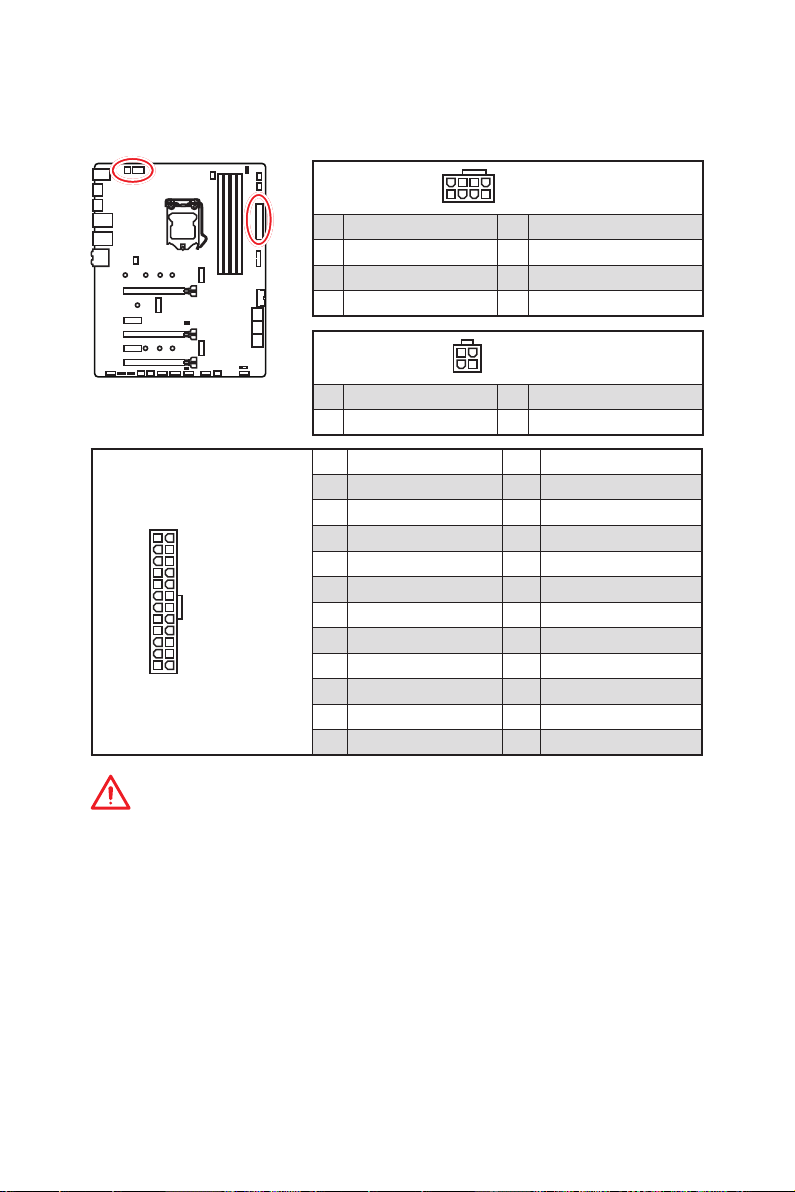
CPU_PWR1~2, ATX_PWR1: Power Connectors
These connectors allow you to connect an ATX power supply.
4
2 1
5
3
CPU_PWR1
CPU_PWR2
8
4 1
1 Ground 5 +12V
2 Ground 6 +12V
3 Ground 7 +12V
4 Ground 8 +12V
1 Ground 3 +12V
2 Ground 4 +12V
1 +3.3V 13 +3.3V
2 +3.3V 14 -12V
3 Ground 15 Ground
24
12
ATX_PWR1
131
4 +5V 16 PS-ON#
5 Ground 17 Ground
6 +5V 18 Ground
7 Ground 19 Ground
8 PWR OK 20 Res
9 5VSB 21 +5V
10 +12V 22 +5V
11 +12V 23 +5V
12 +3.3V 24 Ground
Important
Make sure that all the power cables are securely connected to a proper ATX power
supply to ensure stable operation of the motherboard.
Overview of Components
19
Page 30
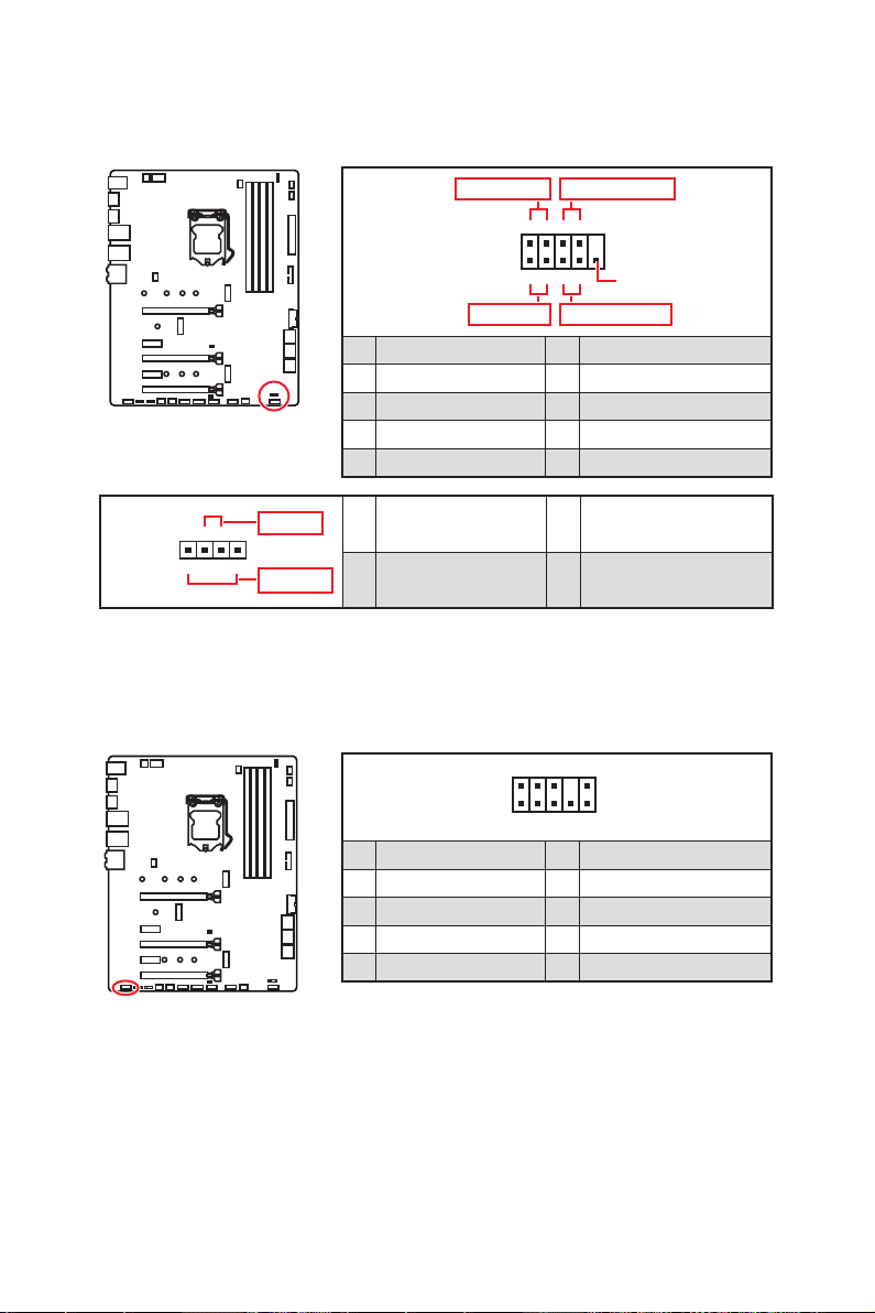
JFP1, JFP2: Front Panel Connectors
These connectors connect to the switches and LEDs on the front panel.
Power LED
JFP1
Power Switch
+++-
--
2 10
1
-
+
HDD LED Reset Switch
1 HDD LED + 2 Power LED +
3 HDD LED - 4 Power LED -
5 Reset Switch 6 Power Switch
7 Reset Switch 8 Power Switch
9 Reserved 10 No Pin
1 Speaker - 2 Buzzer +
3 Buzzer - 4 Speaker +
JFP2
Buzzer
++-
1
Speaker
JAUD1: Front Audio Connector
This connector allows you to connect audio jacks on the front panel.
2 10
1
1 MIC L 2 Ground
3 MIC R 4 NC
5 Head Phone R 6 MIC Detection
7 SENSE_SEND 8 No Pin
9 Head Phone L 10 Head Phone Detection
9
9
Reserved
Overview of Components
20
Page 31

JUSB3~4: USB 3.1 Gen1 Connectors
These connectors allow you to connect USB 3.1 Gen1 ports on the front panel.
10 11
1
20
1 Power 11 USB2.0+
2 USB3_RX_DN 12 USB2.0-
3 USB3_RX_DP 13 Ground
4 Ground 14 USB3_TX_C_DP
5 USB3_TX_C_DN 15 USB3_TX_C_DN
6 USB3_TX_C_DP 16 Ground
7 Ground 17 USB3_RX_DP
8 USB2.0- 18 USB3_RX_DN
9 USB2.0+ 19 Power
10 NC 20 No Pin
Important
Note that the Power and Ground pins must be connected correctly to avoid possible
damage.
JUSB1~2: USB 2.0 Connectors
2 10
1
9
1 VCC 2 VCC
3 USB0- 4 USB1-
5 USB0+ 6 USB1+
7 Ground 8 Ground
9 No Pin 10 NC
Important
y
Note that the VCC and Ground pins must be connected correctly to avoid possible
damage.
y
In order to recharge your iPad,iPhone and iPod through USB ports, please install MSI
DRAGON CENTER utility.
Overview of Components
21
Page 32

CPU_FAN1, PUMP_FAN1, SYS_FAN1~5: Fan Connectors
Fan connectors can be classified as PWM (Pulse Width Modulation) Mode or DC Mode.
PWM Mode fan connectors provide constant 12V output and adjust fan speed with
speed control signal. DC Mode fan connectors control fan speed by changing voltage.
When you plug a 3-pin (Non-PWM) fan to a fan connector in PWM mode, the fan speed
will always maintain at 100%, which might create a lot of noise. You can follow the
instruction below to adjust the fan connector to PWM or DC Mode.
Default PWM Mode fan connectors
1
CPU_FAN1/ PUMP_FAN1
Default DC Mode fan connectors
1
1
SYS_FAN1~2
Switching fan mode and adjusting fan speed
You can switch between PWM mode and DC mode and adjust fan speed in BIOS >
HARDWARE MONITOR.
Select PWM mode or DC mode
SYS_FAN3~5
There are gradient points of the fan speed that allow you to adjust
fan speed in relation to CPU temperature.
Important
Make sure fans are working properly after switching the PWM/ DC mode.
Pin definition of fan connectors
PWM Mode pin definition
1 Ground 2 +12V
3 Sense 4 Speed Control Signal
Overview of Components
22
1 Ground 2 Voltage Control
3 Sense 4 NC
DC Mode pin definition
Page 33

JCOM1: Serial Port Connector
This connector allows you to connect the optional serial port with bracket.
2 10
1
9
1 DCD 2 SIN
3 SOUT 4 DTR
5 Ground 6 DSR
7 RTS 8 CTS
9 RI 10 No Pin
JCI1: Chassis Intrusion Connector
This connector allows you to connect the chassis intrusion switch cable.
Normal
(default)
Trigger the chassis
intrusion event
Using chassis intrusion detector
1. Connect the JCI1 connector to the chassis intrusion switch/ sensor on the chassis.
2. Close the chassis cover.
3. Go to BIOS > SETTINGS > Security > Chassis Intrusion Configuration.
4. Set Chassis Intrusion to Enabled.
5. Press F10 to save and exit and then press the Enter key to select Yes .
6. Once the chassis cover is opened again, a warning message will be displayed on
screen when the computer is turned on.
Resetting the chassis intrusion warning
1. Go to BIOS > SETTINGS > Security > Chassis Intrusion Configuration.
2. Set Chassis Intrusion to Reset.
3. Press F10 to save and exit and then press the Enter key to select Yes .
Overview of Components
23
Page 34

JTPM1: TPM Module Connector
This connector is for TPM (Trusted Platform Module). Please refer to the TPM security
platform manual for more details and usages.
2 14
1
1 LPC Clock 2 3V Standby power
3 LPC Reset 4 3.3V Power
5 LPC address & data pin0 6 Serial IRQ
7 LPC address & data pin1 8 5V Power
9 LPC address & data pin2 10 No Pin
11 LPC address & data pin3 12 Ground
13 LPC Frame 14 Ground
13
JBAT1: Clear CMOS (Reset BIOS) Jumper
There is CMOS memory onboard that is external powered from a battery located on
the motherboard to save system configuration data. If you want to clear the system
configuration, set the jumpers to clear the CMOS memory.
Keep Data
(default)
Clear CMOS/
Reset BIOS
Resetting BIOS to default values
1. Power off the computer and unplug the power cord
2. Use a jumper cap to short JBAT1 for about 5-10 seconds.
3. Remove the jumper cap from JBAT1.
4. Plug the power cord and power on the computer.
Overview of Components
24
Page 35

JRGB1~2, JRAINBOW1: RGB LED connectors
The JRGB connector allows you to connect the 5050 RGB LED strips 12V. The
JRAINBOW connector allows you to connect the WS2812B Individually Addressable
RGB LED strips 5V.
JRGB2
1
JRGB1
1 +12V 2 G
3 R 4 B
JRGB2
1
JRGB1
JRAINBOW1
1
1
Extension cable
JRGB
LED strip
JRAINBOW1
1 +5V 2 Data
3 No Pin 4 Ground
1
JRAINBOW
Rainbow RGB LED
extension cable
WS2812B Individually
Addressable RGB LED strips 5V
CAUTION
Do not connect the wrong type of LED strips. The JRGB connector and the JRAINBOW
connector provide different voltages, and connecting the 5V LED strip to the JRGB
connector will result in damage to the LED strip.
Important
y
The JRGB connector supports up to 2 meters continuous 5050 RGB LED strips
(12V/G/R/B) with the maximum power rating of 3A (12V).
y
The JRAINBOW connector supports up to 72 LEDs WS2812B Individually Addressable
RGB LED strips (5V/Data/Ground) with the maximum power rating of 3A (5V).
y
Always turn off the power supply and unplug the power cord from the power outlet
before installing or removing the RGB LED strip.
y
Please use MSI’s software to control the extended LED strip.
Overview of Components
25
Page 36

Onboard LEDs
EZ Debug LED
These LEDs indicate the debug status of the motherboard.
CPU - indicates CPU is not detected or fail.
DRAM - indicates DRAM is not detected or fail.
VGA - indicates GPU is not detected or fail.
BOOT - indicates the booting device is not detected
DIMM LEDs
These LED indicate the memory modules are installed.
or fail.
DIMM LEDs
Onboard LEDs
26
Page 37

Installing OS, Drivers & Utilities
Please download and update the latest utilities and drivers at www.msi.com
Installing Windows® 10
1.
Power on the computer.
2.
Insert the Windows
3.
Press the Restart button on the computer case.
4.
Press F11 key during the computer POST (Power-On Self Test) to get into Boot
Menu.
5.
Select the Windows
6.
Press any key when screen shows Press any key to boot from CD or DVD...
message.
7.
Follow the instructions on the screen to install Windows
Installing Drivers
1.
Start up your computer in Windows® 10.
2.
Insert MSI
3.
Click the Select to choose what happens with this disc pop-up notification, then
select Run DVDSetup.exe to open the installer. If you turn off the AutoPlay feature
from the Windows Control Panel, you can still manually execute the DVDSetup.exe
from the root path of the MSI Driver Disc.
4.
The installer will find and list all necessary drivers in the Drivers/Software tab.
5.
Click the Install button in the lower-right corner of the window.
6.
The drivers installation will then be in progress, after it has finished it will prompt
you to restart.
7.
Click OK button to finish.
8.
Restart your computer.
®
®
10 installation disc/USB into your computer.
®
10 installation disc/USB from the Boot Menu.
Driver Disc into your optical drive.
®
10.
Installing Utilities
Before you install utilities, you must complete drivers installation.
1.
Open the installer as described above.
2.
Click the Utilities tab.
3.
Select the utilities you want to install.
4.
Click the Install button in the lower-right corner of the window.
5.
The utilities installation will then be in progress, after it has finished it will prompt
you to restart.
6.
Click OK button to finish.
7.
Restart your computer.
Installing OS, Drivers & Utilities
27
Page 38

BIOS Setup
The default settings offer the optimal performance for system stability in normal
conditions. You should always keep the default settings to avoid possible system
damage or failure booting unless you are familiar with BIOS.
Important
y
BIOS items are continuously update for better system performance. Therefore, the
description may be slightly different from the latest BIOS and should be for reference
only. You could also refer to the HELP information panel for BIOS item description.
y
The pictures in this chapter are for reference only and may vary from the product you
purchased.
Entering BIOS Setup
Please refer the following methods to enter BIOS setup.
y Press Delete key, when the Press DEL key to enter Setup Menu, F11 to enter Boot
Menu message appears on the screen during the boot process.
y In MSI Dragon Center application, click on GO2BIOS button and choose OK. The
system will reboot and enter BIOS setup directly.
Function key
F1: General Help
F2: Add/ Remove a favorite item
F3: Enter Favorites menu
F4: Enter CPU Specifications menu
F5: Enter Memory-Z menu
F6: Load optimized defaults
F7: Switch between Advanced mode and EZ mode
F8: Load Overclocking Profile
F9: Save Overclocking Profile
F10: Save Change and Reset*
F12: Take a screenshot and save it to USB flash drive (FAT/ FAT32 format only).
Ctrl+F: Enter Search page
* When you press F10, a confirmation window appears and it provides the modification
information. Select between Yes or No to confirm your choice.
Resetting BIOS
You might need to restore the default BIOS setting to solve certain problems. There are
several ways to reset BIOS:
y Go to BIOS and press F6 to load optimized defaults.
y Short the Clear CMOS jumper on the motherboard.
BIOS Setup
28
Page 39

Important
Be sure the computer is off before clearing CMOS data. Please refer to the Clear
CMOS jumper section for resetting BIOS.
Updating BIOS
Updating BIOS with M-FLASH
Before updating:
Please download the latest BIOS file that matches your motherboard model from MSI
website. And then save the BIOS file into the USB flash drive.
Updating BIOS:
1. Insert the USB flash drive that contains the update file into the USB port.
2. Please refer the following methods to enter flash mode.
Reboot and press Ctrl + F5 key during POST and click on Yes to reboot the
system.
Reboot and press Del key during POST to enter BIOS. Click the M-FLASH button
and click on Yes to reboot the system.
3. Select a BIOS file to perform the BIOS update process.
4. After the flashing process is 100% completed, the system will reboot
automatically.
Updating the BIOS with MSI DRAGON CENTER
Before updating:
Make sure the LAN driver is already installed and the Internet connection is set
properly.
Updating BIOS:
1. Install and launch MSI DRAGON CENTER.
2. Select BIOS Update.
3. Click on Scan button.
4. Click on Download icon to download and install the latest BIOS file.
5. Click Next and choose In Windows mode. And then click Next and Start to start
updating BIOS.
6. After the flashing process is 100% completed, the system will restart
automatically.
BIOS Setup
29
Page 40

EZ Mode
At EZ mode, it provides the basic system information and allows you to configure the
basic setting. To configure the advanced BIOS settings, please enter the Advanced
Mode by pressing the Setup Mode switch or F7 function key.
XMP switch
GAME BOOST
switch
Information
display
M-Flash
Favorites
Hardware
Monitor
y GAME BOOST switch - click on it to toggle the GAME BOOST for OC.
y XMP switch - click on the inner circle to enable/ disable the X.M.P. (Extreme Memory
Profile). Switch the outer circle to select the X.M.P. profile. This switch will only be
available if the X.M.P. supported memory module is installed.
y Setup Mode switch - press this tab or the F7 key to switch between Advanced mode
and EZ mode.
y Screenshot - click on this tab or the F12 key to take a screenshot and save it to USB
flash drive (FAT/ FAT32 format only).
y Search - click on this tab or the Ctrl+F keys and the search page will show. It allows
you to search BIOS item by key word. Move the mouse over a blank space and right
click the mouse to exit search page.
Important
In search page, only the F6, F10 and F12 function keys are available.
y Language - allows you to select the language of BIOS setup.
y System information - shows the CPU/ DDR speed, CPU/ MB temperature, MB/ CPU
type, memory size, CPU/ DDR voltage, BIOS version and build date.
y Boot device priority bar - you can move the device icons to change the boot priority.
The boot priority from high to low is left to right.
SearchScreenshotSetup Mode switch
Language
System
information
Boot device
priority bar
Function
buttons
30
BIOS Setup
Page 41

y Information display - click on the CPU, Memory, Storage, Fan Info and Help buttons
on left side to display related information.
y Function buttons - enable or disable the LAN Option ROM, M.2/ Optane Genie, HD
audio controller, AHCI/ RAID, CPU Fan Fail Warning Control and BIOS Log Review by
clicking on their respective button.
y M-Flash - click on this button to perform M-Flash function that provides the way to
update BIOS with a USB flash drive.
y Hardware Monitor - click on this button to display the Hardware Monitor menu that
allows you to manually control the fan speed by percentage.
y Favorites menu - press the F3 key to enter Favorites menu. It allows you to create
personal BIOS menu where you can save and access favorite/ frequently-used BIOS
setting items.
Default HomePage - allows you to select a BIOS menu (e.g. SETTINGS, OC...,etc)
as the BIOS home page.
Favorite1~5 page - allows you to add the frequently-used/ favorite BIOS setting
items in one page.
To add a BIOS item to a favorite page (Favorite 1~5)
1. Move the mouse over a BIOS item not only on BIOS menu but also on search
page.
2. Right-click or press F2 key.
3. Choose a favorite page and click on OK.
To delete a BIOS item from favorite page
1. Move the mouse over a BIOS item on favorite page (Favorite 1~5)
2. Right-click or press F2 key.
3. Choose Delete and click on OK.
BIOS Setup
31
Page 42

Advanced Mode
Press Setup Mode switch or F7 function key can switch between EZ Mode and
Advanced Mode in BIOS setup.
XMP switch
GAME BOOST
switch
BIOS menu
selection
Menu display
SearchScreenshotSetup Mode switch
Language
System
information
Boot device
priority bar
BIOS menu
selection
y GAME BOOST switch/ XMP switch/ Setup Mode switch/ Screenshot/ Language/
Search/ System information/ Boot device priority bar - please refer to the
descriptions of EZ Mode Overview section.
y BIOS menu selection - the following options are available:
SETTINGS - allows you to specify the parameters for chipset and boot devices.
OC - allows you to adjust the frequency and voltage. Increasing the frequency may
get better performance.
M-FLASH - provides the way to update BIOS with a USB flash drive.
OC PROFILE - allows you to manage overclocking profiles.
HARDWARE MONITOR - allows you to set the speeds of fans and monitor voltages
of system.
BOARD EXPLORER - provides the information of installed devices on this
motherboard.
y Menu display - provides BIOS setting items and information to be configured.
32
BIOS Setup
Page 43

OC Menu
This menu is for advanced users who want to overclock the motherboard.
Important
y
Overclocking your PC manually is only recommended for advanced users.
y
Overclocking is not guaranteed, and if done improperly, it could void your warranty or
severely damage your hardware.
y
If you are unfamiliar with overclocking, we advise you to use GAME BOOST function
for easy overclocking.
f OC Explore Mode [Normal]
Enables or disables to show the normal or expert version of OC settings.
[Normal] Provides the regular OC settings in BIOS setup.
[Expert] Provides the advanced OC settings for OC expert to configure in BIOS
Note: We use * as the symbol for the OC settings of Expert mode.
setup.
f CPU Ratio [Auto]
Sets the CPU ratio that is used to determine CPU clock speed. This item only appears
when CPU Ratio Apply Mode set to All Core.
f Adjusted CPU Frequency
Shows the adjusted CPU frequency. Read-only.
f CPU Ratio Offset When Running AVX [Auto]
Sets a offset value to lower the CPU core ratio. It could be helpful for heat dissipation
when running AVX instruction set. If set to Auto, BIOS will configure this setting
automatically. This item appears when the installed CPU supports this function.
f Ring Ratio [Auto]
Sets the ring ratio. The valid value range depends on the installed CPU.
f Adjusted Ring Frequency
Shows the adjusted Ring frequency. Read-only.
BIOS Setup
33
Page 44

f GT Ratio [Auto]
Sets the integrated graphics ratio. The valid value range depends on the installed
CPU.
f Adjusted GT Frequency
Shows the adjusted integrated graphics frequency. Read-only.
f Misc Setting*
Press Enter, + or - key to open or close the following 3 items related to CPU features.
fEIST [Enabled]*
®
Enables or disables the Enhanced Intel
SpeedStep Technology.
[Enabled] Enables the EIST to adjust CPU voltage and core frequency
dynamically. It can decrease average power consumption and
average heat production.
[Disabled] Disables EIST.
fIntel Turbo Boost [Enabled]*
Enables or disables the Intel
®
Turbo Boost. This item appears when the installed
CPU supports this function.
[Enabled] Enables this function to boost CPU performance automatically above
rated specifications when system request the highest performance
state.
[Disabled] Disables this function.
fEnhanced Turbo [Auto]*
Enables or disables Enhanced Turbo function for all CPU cores to boost CPU
performance. This item appears when the installed CPU supports this function.
[Auto] This setting will be configured automatically by BIOS.
[Enabled] All CPU cores would be increased to maximum turbo ratio.
[Disabled] Disables this function.
f CPU Base Clock (MHz) [Default]
Sets the CPU Base clock. You may overclock the CPU by adjusting this value. Please
note that overclocking behavior and stability is not guaranteed. This item appears
when a CPU that support this function is installed.
f Extreme Memory Profile (X.M.P.) [Disabled]
X.M.P. (Extreme Memory Profile) is the overclocking technology by memory module.
Please enable XMP or select a profile of memory module for overclocking the memory.
This item will be available when the memory modules that support X.M.P. is installed.
f DRAM Frequency [Auto]
Sets the DRAM frequency. Please note the overclocking behavior is not guaranteed.
f Adjusted DRAM Frequency
Shows the adjusted DRAM frequency. Read-only.
f Memory Try It ! [Disabled]
It improve memory compatibility or performance by choosing optimized memory
preset.
BIOS Setup
34
Page 45

f Advanced DRAM Configuration
Press Enter to enter the sub-menu. User can set the memory timing for each/ all
memory channel. The system may become un-stable or un-bootable after changing
memory timing. If it occurs, please clear the CMOS data and restore the default
settings. (Refer to the Clear CMOS jumper/ button section to clear the CMOS data, and
enter the BIOS to load the default settings.)
f Memory Fast Boot [Auto]*
Enables or disables the initiation and training for memory every booting.
[Auto] The setting will be configured automatically by BIOS.
[Enabled] System will completely keep the archives of first intiation and training
[Disabled] The memory will be initialed and trained every booting.
f DigitALL Power
Press Enter to enter the sub-menu. In the sub-menu, you can setup some protecting
conditions about voltage/ current/ temputure for CPU.
f CPU Voltages control [Auto]
These options allows you to set the voltages related to CPU. If set to Auto, BIOS will
set these voltages automatically or you can set it manually.
f DRAM Voltages control [Auto]
These options allows you to set the voltages related to memory. If set to Auto, BIOS
will set these voltages automatically or you can set it manually.
f CPU Memory Changed Detect [Enabled]*
Enables or disables the system to issue a warning message during boot when the CPU
or memory has been replaced.
[Enabled] The system will issue a warning message during boot and then you have
[Disabled] Disables this function and keeps the current BIOS settings.
f CPU Specifications
Press Enter to enter the sub-menu. This sub-menu displays the information of
installed CPU. You can also access this information menu at any time by pressing [F4].
Read only.
for memory. So the memory will not be initialed and trained when
booting to accelerate the system booting time.
to load the default settings for new devices.
fCPU Technology Support
Press Enter to enter the sub-menu. The sub-menu shows the key features of
installed CPU. Read only.
f MEMORY-Z
Press Enter to enter the sub-menu. This sub-menu displays all the settings and
timings of installed memory. You can also access this information menu at any time by
pressing [F5].
fDIMMA1/A2/B1/B2 Memory SPD
Press Enter to enter the sub-menu. The sub-menu displays the information of
installed memory. Read only.
BIOS Setup
35
Page 46

f CPU Features
Press Enter to enter the sub-menu.
fHyper-Threading [Enabled]
Intel Hyper-Threading technology treats the multi cores inside the processor as
multi logical processors that can execute instructions simultaneously. In this way,
the system performance is highly improved. This item appears when the installed
CPU supports this technology.
[Enable] Enables Intel Hyper-Threading technology.
[Disabled] Disables this item if the system does not support HT function.
fActive Processor Cores Control [All]
Allows you to select the number of active CPU cores.
fLimit CPUID Maximum [Disabled]
Enables or disables the extended CPUID value.
[Enabled] BIOS limits the maximum CPUID input value to circumvent boot
[Disabled] Use the actual maximum CPUID input value.
fIntel Virtualization Tech [Enabled]
Enables or disables Intel Virtualization technology.
[Enabled] Enables Intel Virtualization technology and allows a platform to run
[Disabled] Disables this function.
fIntel VT-D Tech [Disabled]
Enables or disables Intel VT-D (Intel Virtualization for Directed I/O) technology.
fHardware Prefetcher [Enabled]
Enables or disables the hardware prefetcher (MLC Streamer prefetcher).
[Enabled] Allows the hardware prefetcher to automatically pre-fetch data
[Disabled] Disables the hardware prefetcher.
fAdjacent Cache Line Prefetch [Enabled]
Enables or disables the CPU hardware prefetcher (MLC Spatial prefetcher).
[Enabled] Enables adjacent cache line prefetching for reducing the cache
[Disabled] Enables the requested cache line only.
fCPU AES Instructions [Enabled]
Enables or disables the CPU AES (Advanced Encryption Standard-New
Instructions) support. This item appears when a CPU supports this function.
problems with older operating system that do not support the
processor with extended CPUID value.
multiple operating systems in independent partitions. The system
can function as multiple systems virtually.
and instructions into L2 cache from memory for tuning the CPU
performance.
latency time and tuning the performance to the specific application.
36
BIOS Setup
Page 47

fIntel Adaptive Thermal Monitor [Enabled]
Enables or disables the Intel adaptive thermal monitor function to protect the CPU
from overheating.
[Enabled] Throttles down the CPU core clock speed when the CPU is over the
adaptive temperature.
[Disabled] Disables this function.
fIntel C-State [Auto]
Enables or disables the Intel C-state. C-state is a processor power management
technology defined by ACPI.
[Auto] This setting will be configured automatically by BIOS.
[Enabled] Detects the idle state of system and reduce CPU power consumption
accordingly.
[Disabled] Disable this function.
fC1E Support [Disabled]
Enables or disables the C1E function for power-saving in halt state. This item
appears when Intel C-State is enabled.
[Enabled] Enables C1E function to reduce the CPU frequency and voltage for
power-saving in halt state.
[Disabled] Disables this function.
fPackage C State limit [Auto]
This item allows you to select a CPU C-state level for power-saving when system is
idle. The options of C-state depend on the installed CPU. This item appears when
Intel C-State is enabled.
fCFG Lock [Enabled]
Lock or un-lock the MSR 0xE2[15], CFG lock bit.
[Enabled] Locks the CFG lock bit.
[Disabled] Un-locks the CFG lock bit.
fEIST [Enabled]
Enables or disables the Enhanced Intel
®
SpeedStep Technology. This item will
appear when OC Explore Mode is set to Normal.
[Enabled] Enables the EIST to adjust CPU voltage and core frequency
dynamically. It can decrease average power consumption and
average heat production.
[Disabled] Disables EIST.
fIntel Turbo Boost [Enabled]
Enables or disables the Intel
®
Turbo Boost. This item is for Normal mode and
appears when a CPU that support Turbo Boost is installed.
[Enabled] Enables this function to boost CPU performance automatically over
specification when system request the highest performance state.
[Disabled] Disables this function.
BIOS Setup
37
Page 48

fLong Duration Power Limit (W) [Auto]
Sets the long duration TDP power limit for CPU in Turbo Boost mode.
fLong Duration Maintained (s) [Auto]
Sets the maintaining time for Long duration power Limit(W).
fShort Duration Power Limit (W) [Auto]
Sets the short duration TDP power limit for CPU in Turbo Boost mode.
fCPU Current Limit (A) [Auto]
Sets maximum current limit of CPU package in Turbo Boost mode. When the
current is over the specified value, the CPU will automatically reduce the core
frequency for reducing the current.
fFCLK Frequency [Auto]
Sets FCLK frequency. Lower FCLK frequency may help you to set higher base clock
frequency.
fDMI Link Speed [Auto]
Sets DMI speed.
fSW Guard Extensions (SGX) [Software Control]
Enables or disables Intel SGX.
fIntel Speed Shift Technology [Auto]
Enables or disables Intel Speed Shift Technology. It can optimize energy efficiency.
This item is only available with the CPU that supports this technology.
38
BIOS Setup
Page 49

Table des matières
Informations de sécurité ....................................................................................... 2
Spécifications ......................................................................................................... 3
Contenu .................................................................................................................. 8
Panneau arrière Entrée/ Sortie ............................................................................ 9
Tableau explicatif de l’état de la LED du port LAN ............................................... 9
Configuration des ports audio ................................................................................ 9
Realtek Audio Console ......................................................................................... 10
Vue d’ensemble des composants ....................................................................... 12
Socket processeur ................................................................................................ 13
Slots DIMM ........................................................................................................... 14
PCI_E1~5: Slots d’extension PCIe ....................................................................... 15
M2_1~2: Slots M.2 (Touche M) .............................................................................. 16
SATA1~6 : Connecteurs SATA 6 Gb/s ................................................................... 17
CPU_PWR1~2, ATX_PWR1: Connecteurs d’alimentation ................................... 19
JFP1, JFP2:Connecteurs de panneau avant ........................................................ 20
JAUD1 : Connecteur audio avant .......................................................................... 20
JUSB3~4: Connecteurs USB 3.1 Gen1 ................................................................. 21
JUSB1~2 : Connecteurs USB 2.0 .......................................................................... 21
CPU_FAN1, PUMP_FAN1, SYS_FAN1~4 : Connecteurs pour ventilateurs .......... 22
JCOM1 : Connecteur de port série ....................................................................... 23
JCI1 : Connecteur intrusion châssis .................................................................... 23
JTPM1 : Connecteur de module TPM ................................................................... 24
JBAT1 : Cavalier Clear CMOS (Réinitialisation BIOS) .......................................... 24
JRGB1~2, JRAINBOW1: Connecteurs LED RGB .................................................. 25
Indicateurs LED embarqués ................................................................................26
EZ Debug LED ....................................................................................................... 26
Indicateurs LED des barrettes DIMM ................................................................... 26
Installer OS, Pilotes & Utilitaires ........................................................................ 27
Installer Windows® 10 .......................................................................................... 27
Installer les pilotes ............................................................................................... 27
Installer les utilitaires .......................................................................................... 27
Configuration du BIOS ......................................................................................... 28
Entrer dans l’interface Setup du BIOS ................................................................ 28
Réinitialiser le BIOS .............................................................................................. 29
Mettre le BIOS à jour ............................................................................................ 29
EZ Mode (mode simplifié) ..................................................................................... 30
Advanced Mode (mode avancé) ........................................................................... 32
OC Menu (menu overclocking)..............................................................................33
Table des matières
1
Page 50

Informations de sécurité
y Les composants dans l’emballage peuvent être endommagés par des décharges
électrostatiques (ESD). Pour vous assurer de correctement monter votre ordinateur,
veuillez vous référer aux instructions ci-dessous.
y Assurez-vous de bien connecter tous les composants. En cas de mauvaise
connexion, il se peut que l’ordinateur ne reconnaisse pas le composant et que le
démarrage échoue.
y Veuillez tenir la carte mère par les bords pour éviter de toucher les composants
sensibles.
y Il est recommandé de porter un bracelet antistatique lors de la manipulation de la
carte mère pour prévenir tout dommage. Si vous n’avez pas de bracelet antistatique,
touchez un objet métallique relié à la terre avant de manipuler la carte mère afin de
vous décharger de votre charge statique. Touchez régulièrement l’objet métallique
pendant toute la manipulation.
y Tant que la carte mère n’est pas installée, conservez-la dans un récipient protégé
contre les ondes électrostatiques ou sur une couche antistatique.
y Avant de démarrer l’ordinateur, vérifiez si toutes les vis et les composants
métalliques sont bien fixés sur la carte mère ou ailleurs dans le boîtier de
l’ordinateur.
y Ne démarrez pas l’ordinateur avant d’avoir terminé l’installation. Ceci peut
endommager les composants ou vous blesser.
y Si vous avez besoin d’aide pendant l’installation, veuillez consulter un technicien
informatique certifié.
y Avant d’installer les composants d’ordinateur, veuillez toujours mettre hors tension
et débrancher le cordon d’alimentation.
y Gardez ce manuel pour références futures.
y Protégez ce manuel contre l’humidité.
y Avant de brancher le bloc d’alimentation sur la sortie électrique, veuillez
vous assurer que la tension de la sortie électrique est bien égale à celle du bloc
d’alimentation.
y Placez le cordon d’alimentation de façon à éviter que l’on marche dessus. Ne posez
rien sur le cordon d’alimentation.
y Veuillez prêter attention à toutes les alertes et remarques indiquées sur la carte
mère.
y Dans un cas comme ci-dessous, faites appel au service autorisé pour vérifier votre
carte mère :
Un liquide a pénétré dans l’ordinateur.
La carte mère a été exposée à de l’humidité.
La carte mère ne fonctionne pas comme indiqué dans les instructions.
La carte mère est tombée par terre et a été endommagée.
La carte mère est cassée.
y Ne pas mettre la carte mère dans un environnement dont la température est
supérieure à 60°C (140°F) sous peine de l'endommager.
Informations de sécurité
2
Page 51

Spécifications
Support des processeurs de la famille de série 9000 Intel
CPU
Chipset Chipset Intel® Z390
Mémoire
Slots d’extension
Sorties vidéo
intégrées
Core™/ 8ème Gen Intel
pour socket LGA1151
* Veuillez vous au site www.intel.com pour plus d’informations de compatibilité.
y 4 x slots pour mémoire DDR4, support jusqu’à 64 Go*
y Support DDR4 4400(OC)/ 4300(OC)/ 4266(OC)/ 4200(OC)/
4133(OC)/ 4000(OC)/ 3866(OC)/ 3733(OC)/ 3600(OC)/
3466(OC)/ 3400(OC)/ 3333(OC)/ 3300(OC)/ 3200(OC)/ 3000(OC)
/ 2800(OC)/ 2666/ 2400/ 2133 MHz*
y Support mode Double-Canal
y Support non-ECC, mémoire un-buffered
y Support Intel
* Veuillez vous référer au site www.msi.com pour plus d’informations sur la
mémoire compatible.
®
y 3 x slots PCIe 3.0 x16 (support les modes x16/x4/x1)
y 2 x slots PCIe 3.0 x1
y 1 x slot M.2 (Touche E) pour le module Intel
uniquement
y 1 x port HDMI™ 1.4, supportant une résolution maximum
de 4096x2160@24Hz
y 1 x port DisplayPort 1.2, supportant une résolution
maximum de 4096X2304@60Hz
®
Core™ / Pentium® Gold / Celeron®
Extreme Memory Profile (XMP)
®
®
CNVi wireless
Multi-GPU y Support de la technologie AMD
®
Chipset Intel
Z390
y 6 x ports SATA 6 Gb/s*
y 2 x slots M.2 (Touche M)*
M2_1 support jusqu’à PCIe 3.0 x 4 et des périphériques
de stockage SATA 6Gb/s, 2242/ 2260/ 2280/ 22110
Stockage
M2_2 support jusqu’à PCIe 3.0 x 4 et des périphériques
de stockage SATA 6Gb/s, 2242/ 2260/ 2280
®
Intel
* Le slot M.2 et le port SATA partagent la même bande passante. Référez-vous à
la page 17 pour les détails.
**Avant d’utiliser les modules de mémoire Intel
d’avoir mis à jour les pilotes et le BIOS avec la dernière version disponible sur le
site officiel MSI.
Optane™ Memory Ready
Suite du tableau sur la page suivante
®
CrossFire™ 2-Way
®
Optane™, veuillez vous assurer
Spécifications
3
Page 52

Suite du tableau sur la page précédente
RAID
LAN
USB
Audio
Connecteurs sur le
panneau arrière
Chipset Intel
®
Z390
y Support des architectures RAID 0, RAID 1, RAID 5 et RAID
10 pour les périphériques de stockage SATA
y Support des architectures RAID 0, RAID 1 pour les
périphériques de stockage M.2 PCIe
1 x contrôleur Intel I219-V Gigabit LAN
1 x contrôleur Intel I211-AT Gigabit LAN
y Chipset Intel
®
Z390
4 x ports USB 3.1 Gen2 (SuperSpeed USB 10Gbps) (1
port Type-C et 3 ports Type-A sur le panneau arrière)
4 x ports USB 3.1 Gen1 (SuperSpeed USB) disponibles
par l’intermédiaire des connecteurs USB internes
6 x ports USB 2.0 (High-speed USB) (2 ports Type-A
sur le panneau arrière, 4 ports disponibles par
l’intermédiaire des connecteurs USB internes)
®
y Realtek
ALC892 Codec
Audio haute définition 7.1
Support sortie S/PDIF
y 1 x port clavier/ souris PS/2
y 2 x ports USB 2.0 Type-A
y 1 x port DisplayPort
y 1 x port HDMI™2x LAN (RJ45) ports
y 3 x ports USB 3.1 Gen2 Type-A
y 1 x port USB 3.1 Gen2 Type-C
y 5 x jacks audio OFC
y 1 x connecteur Sortie S/PDIF optique
Spécifications
4
Suite du tableau sur la page suivante
Page 53

Suite du tableau sur la page précédente
y 1 x connecteur d’alimentation principal ATX 24 broches
y 1 x connecteur d’alimentation ATX 12V 8 broches
y 1 x connecteur d’alimentation ATX 12V 4 broches
y 6 x connecteurs SATA 6Gb/s
y 2 x connecteurs USB 3.1 Gen1 (support de 4 autres ports
USB 3.1 Gen1)
y 2 x connecteurs USB 2.0 (support de 4 autres ports USB
2.0)
y 1 x connecteur de ventilateurs CPU 4 broches
Connecteurs
internes
Debug LED y 4x EZ Debug LED
y 1 x connecteur de ventilateurs 4 broches pour la pompe à
eau
y 5 x connecteurs de ventilateurs système 4 broches
y 1 x connecteur de port série
y 1 x connecteur audio avant
y 2 x connecteurs de panneau système
y 1 x connecteur intrusion châssis
y 1 x connecteur de module TPM
y 2 x connecteurs LED RGB 4 broches
y 1 x connecteur de LED RAINBOW 3 broches
Contrôleur E/S Contrôleur NUVOTON NCT6797
y Détection de la température du CPU et du système
Moniteur système
Dimensions
Fonctions BIOS
y Détection de la vitesse du ventilateur du CPU et du
système
y Contrôle de la vitesse du ventilateur du CPU et du système
y Format ATX
y 24,3 cm x 30,4 cm (9,6” x 12”)
y 1 x flash BIOS 128 Mb
y UEFI AMI BIOS
y ACPI 6.1, SMBIOS 2.8
y Multilingue
Suite du tableau sur la page suivante
Spécifications
5
Page 54

Logiciel
Fonctions Dragon
Center
Fonctions spéciales
Suite du tableau sur la page précédente
y Pilotes
y DRAGON CENTER
y MYSTIC LIGHT
y Open Broadcaster Software (OBS)
y CPU-Z MSI GAMING
y MSI App Player (BlueStacks)
®
y Intel
Extreme Tuning Utility
y Google Chrome™, Google Toolbar, Google Drive
y Norton™ Internet Security Solution
y GAME OPTIMIZATION
y OC Performance
y Hardware Monitor
y Eyerest
y LAN Manager
y Live Update
Référez-vous au site http://
download.msi.com/manual/mb/
DRAGONCENTER2.pdf pour plus
de détails.
y Audio
Audio Boost
y Network
GAMING LAN with Gaming LAN Manager
Intel CNVi Ready
y Stockage
Twin Turbo M.2
y Cooling
Extended Heatsink Design
Pump Fan
GAMING Fan Control
Spécifications
6
Suite du tableau sur la page suivante
Page 55

Fonctions spéciales
Suite du tableau sur la page précédente
y LED
Mystic Light
Mystic Light Extension (RGB)
Mystic Light Extension (RAINBOW)
Mystic light SYNC
EZ DEBUG LED
y Protection
Steel Armor PCI-E
M.2 Shield Frozr
Pre-installed IO shielding
y Performance
Multi GPU – CrossFire Technology
DDR4 Boost
Core Boost
USB with type A+C
INTEL Turbo USB 3.1 Gen 2
8-pin CPU Power
y VR
VR Ready
y Expérience des joueurs
Contrôle de la souris GAMING
Joueur de APP
APP Player
y BIOS
Click BIOS 5
Spécifications
7
Page 56

Contenu
Vérifiez tous les articles dans le carton d’emballage de votre carte mère.
L’emballage doit contenir :
Carte mère MAG Z390 TOMAHAWK
Câble
Accessoires
DVD d’application DVD de pilotes 1
Documentation
Important
Veuillez contacter votre revendeur si un des éléments ci-dessus est endommagé ou
manquant.
Câble SATA 6Gb/s 2
RGB LED Extension 80cm 1
Vis M.2 1
Insigne pour châssis 1
Carte VIP 1
Manual d’utilisation 1
Guide d’installation rapide 1
8
Contenu
Page 57

Panneau arrière Entrée/ Sortie
PS/2
DisplayPort
LAN LAN
Ports Audio
USB 2.0
USB 3.1 Gen2
Sortie S/PDIF optique
USB 3.1 Gen2 Type-C
Tableau explicatif de l’état de la LED du port LAN
LED indiquant la connexion
et l’activité
Etat Description
Eteint Pas de connexion
Jaune Connexion correcte
Clignote Activité en cours
LED indiquant la vitesse
Status Description
Eteint Débit de 10 Mbps
Vert Débit de 100 Mbps
Orange Débit de 1 Gbps
Configuration des ports audio
Ports Audio
Sortie centre/ Caisson de basse ● ●
Sortie audio haut-parleur arrière ● ● ●
Entrée Ligne/ Sortie audio hautparleur côté
Sortie Ligne/ Sortie casque avant ● ● ● ●
Entrée Microphone
(●: connecté, Espace : vide)
Canal
2 4 6 8
●
Panneau arrière Entrée/ Sortie
9
Page 58

Realtek Audio Console
Après l’installation de Realtek Audio Console, vous pouvez l’utiliser pour modifier les
paramètres du son afin d’obtenir une meilleure expérience sonore.
Sélection du
périphérique
Amélioration d’application
Paramètres avancés
Volume principal
Connector Settings
Jack Status
y Sélection du périphérique - vous permet de sélectionner une source de sortie
audio pour en modifier les paramètres. Le symbole de coche indique le périphérique
sélectionné par défaut.
y Amélioration d’application - les diverses options vous fournissent un guide complet
des effets acoustiques proposés pour les périphériques de sortie et d’entrée.
y Volume principal - contrôle le volume ou équilibre le son gauche/droite des haut-
parleurs branchés sur le panneau avant ou derrière en ajustant la barre de volume.
y Etat des prises Jack - présente tous les périphériques de diffusion et de capture
connectés à votre ordinateur.
y Paramètres du connecteur - configure les paramètres de connexion.
Dialogue popup automatique
Lorsqu’un périphérique est branché sur une prise audio, une fenêtre de dialogue
apparaîtet vous demande de choisir le périphérique connecté que vous souhaitez
utiliser.
Chaque jack est réglé avec ses paramètres par défaut comme indiqué sur la page
suivante.
Important
Les photos ci-dessus ne sont données qu’à titre de référence et peuvent varier selon
le produit que vous achetez.
Panneau arrière Entrée/ Sortie
10
Page 59

Ilustration de l’utilisation des ports audio dédiés au casque et au microphone
Ilustration de l’utilisation du port audio dédié aux haut-parleurs
AUDIO INPUT
Ilustration de l’utilisation des ports audio dédiés aux haut-parleurs 7.1
AUDIO INPUT
Rear Front
Side Center/
Subwoofer
Panneau arrière Entrée/ Sortie
11
Page 60

Vue d’ensemble des composants
DIMMA1
DIMMA2
DIMMB1
CPU_PWR2
CPU_PWR1
Socket
processeur
CPU_FAN1
DIMMB2
JRGB2
PUMP_FAN1
SYS_FAN1
ATX_PWR1
SYS_FAN2
PCI_E1
CNVI_1
JBAT1
PCI_E2
PCI_E3
PCI_E4
PCI_E5
JAUD1
JRGB1
JRAINBOW1
SYS_FAN3
SYS_FAN4
JCOM1
JTPM1
JUSB1
JCI1
JUSB2
SYS_FAN5
JUSB3
M2_1
JUSB4
SATA▼1▲2
SATA▼3▲4
SATA▼5▲6
M2_2
JFP2
JFP1
Vue d’ensemble des composants
12
Page 61

Socket processeur
Distance entre le centre du CPU
et le slot DIMM le plus proche.
50.77 mm
Présentation du socket LGA 1151
Sur le socket LGA 1151, vous
remarquerez deux encoches et un
triangle jaune servant d’indicateur
pour placer le processeur dans la bonne
position sur la carte mère. Le triangle
jaune correspond à la broche 1 du
processeur.
Important
y
Avant d’installer ou de retirer le processeur du socket, veillez à toujours débrancher
le câble d’alimentation de la prise électrique.
y
Veuillez garder le capot de protection du processeur après l’installation du
processeur. Selon les exigences de RMA (Return Merchandise Authorization), MSI
n’acceptera pas les cartes mère dont le capot de protection aura été retiré.
y
Lors de l’installation d’un processeur, n’oubliez pas d’installer un ventilateur pour
processeur. Un ventilateur de processeur est nécessaire pour protéger le processeur
contre la surchauffe et maintenir la stabilité du système.
y
Assurez-vous de l’étanchéité entre le ventilateur et le processeur avant de démarrer
votre système.
y
La surchauffe peut facilement endommager le processeur et la carte mère.
Assurez-vous toujours que le système de refroidissement fonctionne correctement
pour protéger le processeur de la surchauffe. Assurez-vous d’appliquer une couche
de pâte thermique (ou adhésif thermique) entre le processeur et le système de
refroidissement afin d’améliorer la dissipation de la chaleur.
y
Quand le processeur n’est pas installé, protégez toujours les broches de
l’emplacement du processeur avec le couvercle dédié.
y
Si vous avez achetez un processeur indépendamment du ventilateur, veuillez vous
référer à la documentation dans le paquet du ventilateur pour plus d’informations
concernant l’installation.
y
Cette carte mère supporte l’overclocking. Néanmoins, veuillez vous assurer que vos
composants soient capables de tolérer l’overclocking. Prenez note que l’utilisation
au-delà des spécifications du constructeur n’est pas recommandée. MSI
pas les dommages et risques causés par les utilisations non prévues dans les
spécifications du produit.
®
ne garantit
Vue d’ensemble des composants
13
Page 62

Slots DIMM
DIMMA1 DIMMB1
Canal A CanalB
DIMMA2 DIMMB2
Installation recommandée de module mémoire
DIMMB2 DIMMB2
DIMMA2 DIMMA2 DIMMA2
DIMMB1
DIMMA1
Important
y
Veillez à toujours insérer un module de mémoire dans l’emplacement DIMMA2 en
premier.
y
Du fait des ressources utilisées par le chipset, la capacité de mémoire disponible est
un peu moins élevée que celle installée.
y
Basé sur les spécifications du processeur Intel, une tension d’une barrette mémoire
en dessous de 1.35V est conseillée pour protéger le processeur.
y
Veuillez noter que la capacité maximum de la mémoire est de 4 Go ou moins pour
le système d’exploitation Windows 32-bit du fait de la limitation de mémoire. Par
conséquent, il est recommandé d’installer le système d’exploitation Windows 64-bit
si vous voulez installer une mémoire de plus de 4 Go sur la carte mère.
y
Certaines mémoires peuvent fonctionner à une fréquence réduite par rapport à
la valeur indiquée lors de l’overclocking car la fréquence d’opération de mémoire
dépend du Serial Presence Detect (SPD). Rendez-vous sur le BIOS et choisissez la
fonction Memory Try It! pour régler la fréquence de mémoire si vous voulez faire
fonctionner la mémoire à la fréquence indiquée ou à une fréquence plus élevée.
y
Il est recommandé d’utiliser un système de refroidissement qui sera capable de
refroidir toutes les barrettes mémoire et d’offrir de bonnes performances lors d’un
overclocking.
y
La stabilité et la compatibilité du module de mémoire lors de l’overclocking
dépendent du processeur et des périphériques installés.
Vue d’ensemble des composants
14
Page 63

PCI_E1~5: Slots d’extension PCIe
PCI_E1: PCIe 3.0 x16 (CPU lignes)
PCI_E2: PCIe 3.0 x1 (PCH lignes)
PCI_E3: PCIe 3.0 x4 (PCH lignes)
PCI_E4: PCIe 3.0 x1 (PCH lignes)
PCI_E5: PCIe 3.0 x1 (PCH lignes)
Installation recommandée pour une configuration multi-GPU
x16 x16
x4
Important
y
Si vous installez une carte graphique lourde, il vous faut utiliser un outil comme
la barre de support MSI Gaming Series pour supporter son poids et pour éviter la
déformation du slot.
y
Si vous choisissez d’installer une seule carte d’extension PCIe x16, nous vous
recommandons d’utiliser le slot PCI_E1 pour profiter de performances optimales.
y
Veillez à toujours mettre l’ordinateur hors tension et à débrancher le cordon
d’alimentation avant d’installer les cartes d’extension. Référez-vous à la
documentation des cartes pour vérifier si un composant ou un logiciel doit être
modifié.
Vue d’ensemble des composants
15
Page 64

M2_1~2: Slots M.2 (Touche M)
Important
y
La technologie Intel® RST supporte seulement un SSD
M.2 PCIe avec une mémoire ROM UEFI.
y
Intel® Optane™ Memory Ready.
M2_1
M2_2
Installation du SSD M.2
1. Enlevez la vis de la vis de base.
2. Enlevez la vis de base.
3. Fixez la vis de base dans le trou
correspondant à la longueur du module
M.2.
4. Insérez votre module M.2 dans
l’emplacement M.2 à un angle de 30
degrés.
4
Video Demonstration
Watch the video to learn how to Install M.2
module.
http://youtu.be/JCTFABytrYA
5. Positionnez la vis dans
l’encoche située sur le bord du
module M.2 et fixez-la dans la
vis de base.
5
3
1
30°
2
Utilisation de la protection M.2 Shield
Nous fournissons une protection pour le slot M2_1, appelée M.2 Shield. Cette
protection permet de mieux dissiper la chaleur du module M.2. Avant d’installer le
module M.2 pour la première fois, vous devez enlever la vis, soulever le couvercle et
retirer le film de protection et l’anneau de caoutchouc du pad thermique.
Vue d’ensemble des composants
16
Page 65

SATA1~6 : Connecteurs SATA 6 Gb/s
Ces connecteurs utilisent une interface SATA 6 Gb/s. Chaque connecteur peut être
relié à un appareil SATA.
SATA2
SATA1
SATA4
SATA3
SATA6
SATA5
Important
y
Veuillez ne pas plier les câbles SATA à 90° car cela pourrait entraîner une perte de
données pendant la transmission.
y
Les câbles SATA disposent de prises identiques sur chaque côté. Néanmoins, il est
recommandé de connecter la prise plate sur la carte mère pour un gain d’espace.
Tableau de combinaison M.2 et SATA
Slot Connecteurs SATA disponibles
M2_1 PCIe SATA PCIe SATA PCIe SATA
M2_2 PCIe PCIe SATA SATA ─ ─
SATA1 ✓ ✓ ✓ ✓ ✓ ✓
SATA2 ✓ ─ ✓ ─ ✓ ─
SATA3 ✓ ✓ ✓ ✓ ✓ ✓
SATA4 ✓ ✓ ✓ ✓ ✓ ✓
SATA5 ─ ─ ─ ─ ✓ ✓
SATA6 ─ ─ ─ ─ ✓ ✓
(SATA: M.2 SATA SSD, PCIe: M.2 PCIe SSD, ✓: disponible, ─: indisponible)
Vue d’ensemble des composants
17
Page 66

Combinaison des slots M.2
1 x SSD M.2 PCIe + 6 x disques durs
SATA
1x SSD M.2 SATA + 5 x disques durs
SATA
M.2 PCIe
SATA2SATA2SATA2
SATA1SATA1SATA1
SATA4SATA4SATA4
SATA3SATA3SATA3
SATA6
SATA5
2 x SSDs M.2 PCIe + 4 x disques
durs SATA
M.2 PCIe
M.2 PCIe
1 x SSD M.2 PCIe + 1x SSD M.2 SATA
+ 4 x disques durs SATA
M.2 SATA
SATA4SATA4
SATA6
2 x SSDs M.2 SATA + 3x disques
durs SATA
M.2 SATA
M.2 SATA
SATA3SATA3
SATA5
SATA1 SATA1
M.2 PCIe
M.2 SATA
Vue d’ensemble des composants
18
Page 67

CPU_PWR1~2, ATX_PWR1: Connecteurs d’alimentation
Ces connecteurs vous permettent de relier une alimentation ATX.
4
2 1
5
3
CPU_PWR1
CPU_PWR2
8
4 1
1 Ground 5 +12V
2 Ground 6 +12V
3 Ground 7 +12V
4 Ground 8 +12V
1 Ground 3 +12V
2 Ground 4 +12V
1 +3.3V 13 +3.3V
2 +3.3V 14 -12V
3 Ground 15 Ground
24
12
ATX_PWR1
131
4 +5V 16 PS-ON#
5 Ground 17 Ground
6 +5V 18 Ground
7 Ground 19 Ground
8 PWR OK 20 Res
9 5VSB 21 +5V
10 +12V 22 +5V
11 +12V 23 +5V
12 +3.3V 24 Ground
Important
Veuillez vous assurer que tous les câbles d’alimentation sont branchés aux
connecteurs adéquats afin garantir une opération stable de la carte mère.
Vue d’ensemble des composants
19
Page 68

JFP1, JFP2: Connecteurs de panneau avant
Ces connecteurs se lient aux interrupteurs et indicateurs LED du panneau avant.
Power LED
JFP1
HDD LED Reset Switch
1 HDD LED + 2 Power LED +
3 HDD LED - 4 Power LED -
5 Reset Switch 6 Power Switch
7 Reset Switch 8 Power Switch
9 Reserved 10 No Pin
1 Speaker - 2 Buzzer +
3 Buzzer - 4 Speaker +
JFP2
Buzzer
++-
1
Speaker
JAUD1 : Connecteur audio avant
Ce connecteur se lie aux jacks audio du panneau avant.
1 MIC L 2 Ground
3 MIC R 4 NC
5 Head Phone R 6 MIC Detection
7 SENSE_SEND 8 No Pin
9 Head Phone L 10 Head Phone Detection
Power Switch
+++-
--
2 10
1
2 10
1
-
+
9
9
Reserved
Vue d’ensemble des composants
20
Page 69

JUSB3~4: Connecteurs USB 3.1 Gen1
Ces connecteurs vous permettent de relier un port USB 3.1 Gen1 sur le panneau
avant.
10 11
1
20
1 Power 11 USB2.0+
2 USB3_RX_DN 12 USB2.0-
3 USB3_RX_DP 13 Ground
4 Ground 14 USB3_TX_C_DP
5 USB3_TX_C_DN 15 USB3_TX_C_DN
6 USB3_TX_C_DP 16 Ground
7 Ground 17 USB3_RX_DP
8 USB2.0- 18 USB3_RX_DN
9 USB2.0+ 19 Power
10 NC 20 No Pin
Important
Notez que les câbles d’alimentation et de terre doivent être branchés correctement
afin d’éviter d’endommager la carte.
JUSB1~2 : Connecteurs USB 2.0
2 10
1
9
1 VCC 2 VCC
3 USB0- 4 USB1-
5 USB0+ 6 USB1+
7 Ground 8 Ground
9 No Pin 10 NC
Important
y
Notez que les broches VCC et Terre doivent être branchées correctement afin
d’éviter tout dommage sur la carte mère.
y
Pour recharger votre iPad, iPhone et iPod par l’intermédiaire d’un port USB,
veuillez installer l’utilitaire MSI
DRAGON CENTER
Vue d’ensemble des composants
21
Page 70

CPU_FAN1, PUMP_FAN1, SYS_FAN1~4 : Connecteurs pour ventilateurs
Les connecteurs pour ventilateurs peuvent être utilisés en mode PWM (Pulse Width
Modulation) et en mode DC. En mode PWM, les connecteurs fournissent une sortie
de 12V constante et ajustent la vitesse des ventilateurs avec un signal de contrôle
de vitesse. En mode DC, les connecteurs contrôlent la vitesse des ventilateurs en
modifiant la tension. Par conséquent, quand vous branchez un ventilateur à 3 broches
(Non-PWM) à un connecteur de ventilateur de mode PWM, la vitesse sera toujours
maintenue à 100% et cela occasionnera du bruit. Vous pouvez suivre les instructions
ci-dessous pour régler le connecteur de ventilateur en mode PWM ou mode DC.
Connecteurs pour ventilateurs en mode PWM
par défaut
1
CPU_FAN1/ PUMP_FAN1
Connecteurs pour ventilateurs en mode DC
par défaut
1
1
SYS_FAN1~2
Basculer entre les modes des ventilateurs et ajuster la vitesse
Vous pouvez alterner entre le mode PWM et le mode DC et ajuster la vitesse des
ventilateurs dans le BIOS > HARDWARE MONITOR.
Choisissez le mode PWM ou le mode DC
SYS_FAN3~5
Il y a des points de gradient de la vitesse du ventilateur qui
vous permet d’ajuster la vitesse de ventilateur par rapport à la
température du processeur.
Important
Veuillez vous assurer que les ventilateurs fonctionnent correctement après avoir
basculé entre les modes PWM et DC.
Définition des broches des connecteurs de ventilateur
Définition des broches en mode PWM
1 Ground 2 +12V
3 Sense 4 Speed Control Signal
Vue d’ensemble des composants
22
Définition des broches en mode DC
1 Ground 2 Voltage Control
3 Sense 4 NC
Page 71

JCOM1 : Connecteur de port série
Ce connecteur vous permet de relier un port série en option.
2 10
1
9
1 DCD 2 SIN
3 SOUT 4 DTR
5 Ground 6 DSR
7 RTS 8 CTS
9 RI 10 No Pin
JCI1 : Connecteur intrusion châssis
Ce connecteur est relié à un câble d’interrupteur intrusion châssis.
Normal
(défaut)
Commencer l’activité
intrusion châssis
Utilisation du détecteur d’intrusion châssis
1. Reliez le connecteur JCI1 à l’interrupteur ou au capteur d’intrusion châssis situé
sur le boîtier du PC.
2. Fermez le couvercle du boîtier.
3. Allez dans le BIOS > SETTINGS (Réglages) > Security (Sécurité) > Chassis
Intrusion Configuration (Configuration intrusion châssis).
4. Réglez Chassis Intrusion (intrusion châssis) sur Enabled (Activé).
5. Appuyez sur F10 pour sauvegarder et quitter. Ensuite appuyez sur la touche Enter
(Entrée) pour choisir Yes (Oui).
6. Désormais, si le boîtier du PC est ouvert quand l’ordinateur est allumé, vous
recevrez un message d’alerte à l’écran.
Réinitialisation de l’alerte intrusion châssis
1. Allez dans le BIOS > SETTINGS (Réglages) > Security (Sécurité) > Chassis
Intrusion Configuration (Configuration intrusion châssis).
2. Mettez Chassis Intrusion (Intrusion châssis) en Reset (Remettre).
3. Appuyez sur F10 pour sauvegarder et quitter. Ensuite appuyez sur la touche Enter
(Entrée) pour choisir Yes (Oui).
Vue d’ensemble des composants
23
Page 72

JTPM1 : Connecteur de module TPM
Ce connecteur est relié à un module TPM (Trusted Platform Module). Veuillez vous
référer au manuel du module TPM pour plus d’informations.
2 14
1
1 LPC Clock 2 3V Standby power
3 LPC Reset 4 3.3V Power
5 LPC address & data pin0 6 Serial IRQ
7 LPC address & data pin1 8 5V Power
9 LPC address & data pin2 10 No Pin
11 LPC address & data pin3 12 Ground
13 LPC Frame 14 Ground
13
JBAT1 : Cavalier Clear CMOS (Réinitialisation BIOS)
Une mémoire CMOS est intégrée et est alimentée en externe par une batterie située
sur la carte mère afin de conserver les données de configuration système. Si vous
souhaitez nettoyer la configuration système, placez le cavalier sur Effacer CMOS de
manière à nettoyer la mémoire CMOS.
Conserver
les données
(défaut)
Effacer CMOS/
Réinitialiser BIOS
Réinitialiser le BIOS aux valeurs par défaut
1. Eteignez l’ordinateur et débranchez le câble d’alimentation de la prise électrique.
2. Utilisez un couvercle de cavalier pour fermer JBAT1 pour environ 5-10 secondes.
3. Enlevez le couvercle de cavalier du JBAT1.
4. Branchez de nouveau le câble d’alimentation à votre ordinateur et allumez-le.
Vue d’ensemble des composants
24
Page 73

JRGB1~2, JRAINBOW1: Connecteurs LED RGB
Le connecteur JRGB vous permet de connecter un ruban LED RGB de type 5050 12V.
Le connecteur JRAINBOW vous permet de connecter un ruban à LED RGB WS2812B
adressables individuellement 5V.
JRGB2
1
JRGB1
1 +12V 2 G
3 R 4 B
JRGB2
1
JRGB1
JRAINBOW1
1
1
Câble d’extension
JRGB
Ruban LED
JRAINBOW1
1 +5V 2 Data
3 No Pin 4 Ground
1
JRAINBOW
Câble d’extension
pour ruban à LED
de type arc-en-ciel
Ruban LED RGB WS2812B
adressables individuellement,
sortie 5V
ATTENTION
Faites attention à bien connecter le bon type de ruban LED. Le connecteur JRGB et le
connecteur JRAINBOW fournissent des tensions différentes. La connexion d’un ruban
LED 5V au connecteur JRGB1 peut endommager le ruban.
Important
y
Le connecteur JRGB1 supporte jusqu’à des rubans 2 mètres en continu de type 5050
avec une puissance nominale maximale de 3A (12V).
y
Le connecteur JRAINBOW supporte jusqu’à des rubans 72 LEDs WS2812B
adressables individuellement (5V/Data/Ground) avec une puissance nominale
maximale de 3A (5V).
y
Avant d’installer ou de retirer le ruban LED, veillez à toujours éteindre
l’alimentation et à débrancher le câble d’alimentation de la prise électrique.
y
Veuillez utiliser un logiciel MSI dédié pour contrôler le ruban d’extension LED.
Vue d’ensemble des composants
25
Page 74

Indicateurs LED embarqués
EZ Debug LED
Ces LEDs indiquent l’état de débogage de la carte mère.
CPU - indique que le CPU n’est pas détecté ou que
son initialisation a échoué.
DRAM -indique que la mémoire DRAM n’est pas
détectée ou que son initialisation a échoué.
VGA - indique que le GPU n’est pas détecté ou que
son initialisation a échoué.
BOOT - indique que le périphérique de démarrage
Indicateurs LED des barrettes DIMM
Ces LEDs indiquent que les barrettes de mémoire sont installées.
n’est pas détecté ou que son initialisation a
échoué.
Indicateurs LED des barrettes DIMM
Indicateurs LED embarqués
26
Page 75

Installer OS, Pilotes & Utilitaires
Veuillez vous référer au site www.msi.com pour télécharger et mettre à jour les
derniers utilitaires et pilotes.
Installer Windows® 10
1. Allumez l’ordinateur.
2. Insérez le disque de Windows® 10 dans le lecteur optique.
3. Appuyez sur le bouton Restart du boîtier de l’ordinateur.
4. Appuyez sur la touche F11 pendant le POST (Power-On Self Test) du système pour
entrer dans le menu Boot Menu.
5. Choisissez le lecteur optique du Boot Menu.
6. Appuyez sur n’importe quelle touche lorsqu’apparaît le message [Press any key
to boot from CD or DVD].
7. Suivez les instructions à l’écran pour installer Windows
Installer les pilotes
1. Allumez l’ordinateur sous Windows® 10.
®
2. Insérez le disque MSI
3. Cliquez sur la fenêtre popup Choisir quoi faire avec ce disque (Select to choose
what happens with this disc), puis choisissez Lancer DVDSetup.exe (Run
DVDSetup.exe) pour ouvrir l’outil d’installation. Si vous désactivez la fonction
AutoPlay dans le panneau de configuration Windows, vous pouvez quand même
exécuter manuellement DVDSetup.exe à partir du chemin d’accès depuis la
racine du disque de pilotes MSI.
4. L’outil d’installation trouvera et listera tous les pilotes dont vous avez besoin
dans l’onglet Pilotes/Logiciels (Drivers/Software).
5. Cliquez sur le bouton Installer (Install) dans le coin inférieur droit de la fenêtre.
6. L’installation des pilotes commence. Une fois terminée, il vous sera demandé de
redémarrer.
7. Cliquez sur le bouton OK pour terminer.
8. Redémarrez votre ordinateur.
Driver Disc dans le lecteur optique.
®
10.
Installer les utilitaires
Avant d’installer les utilitaires, il faut compléter l’installation des pilotes.
1.
Ouvrez l’outil d’installation comme décrit ci-dessus.
2. Cliquez sur l’onglet Utilities.
3. Choisissez les utilitaires que vous voulez installer.
4.
Cliquez sur le bouton Installer (Install) dans le coin inférieur droit de la fenêtre.
5. L’installation des utilitaires commence. Une fois terminée, il vous sera demandé
de redémarrer.
6. Cliquez sur le bouton OK pour terminer.
7. Redémarrez votre ordinateur.
Installer OS, Pilotes & Utilitaires
27
Page 76

Configuration du BIOS
Les réglages par défaut fournissent une performance optimale pour la stabilité du
système en conditions normales. Veillez à toujours garder les réglages par défaut
pour éviter d’endommager le système ou tout problème au démarrage, sauf si vous
êtes familier avec le BIOS.
Important
y
Le BIOS est constamment mis à jour afin d’offrir de meilleures performances
système. Par conséquent, la description peut différer selon la version de BIOS utilisée
et n’est donc donnée qu’à titre de référence. Vous pouvez aussi vous référer à l’onglet
Help (Aide) pour obtenir la description des fonctions du BIOS.
y
Les photos ne sont données qu’à titre de référence et peuvent varier selon le produit
que vous achetez.
Entrer dans l’interface Setup du BIOS
Pour entrer dans l’interface Setup du BIOS, vous pouvez suivre ces deux méthodes :
y Pendant le démarrage, lorsqu’apparaît le message “Press DEL key to enter Setup
Menu, F11 to enter Boot Menu” sur l’écran, veuillez appuyer sur la touche Suppr.
y Quand l’ordinateur est déjà en marche, vous pouvez utiliser l’application MSI
DRAGON CENTER. Cliquez sur le bouton GO2BIOS puis sur OK. Le système redémarre
et entre dans l’interface Setup du BIOS.
Touches de fonction
F1: Aide générale
F2: Ajouter ou supprimer un élément favori
F3: Entrer dans le menu Favoris
F4: Entrer dans le menu de réglages du processeur
F5: Entrer dans le menu Memory-Z
F6: Charger les réglages par défaut
F7: Alterner entre le mode avancé et le mode simplifié
F8: Charger le profil d’overclocking
F9: Sauvegarder le profil d’overclocking
F10: Sauvegarder les modifications et réglages*
F12: Prendre une capture d’écran et la conserver dans le lecteur flash USB (au
Ctrl+F: Entrer dans la page de recherche
* Lorsque vous appuyez sur F10, une fenêtre de confirmation apparaît et fournit
l’information de modification. Choisissez entre Oui et Non pour confirmer.
format FAT/ FAT32 uniquement).
Configuration du BIOS
28
Page 77

Réinitialiser le BIOS
Il se peut que vous ayez besoin de récupérer les réglages BIOS par défaut pour
résoudre des problèmes. Pour réinitialiser les réglages du BIOS, veuillez suivre l’une
des méthodes suivantes :
y Allez dans le Setup du BIOS et appuyez sur F6 pour charger les réglages par défaut.
y Court-circuitez le cavalier Clear CMOS sur la carte mère.
Important
Assurez-vous que l’ordinateur est éteint avant d’effacer les données CMOS. Veuillez
vous référer à la section cavalier Clear CMOS pour en savoir plus sur la réinitialisation
du BIOS.
Mettre le BIOS à jour
Mettre le BIOS à jour avec M-FLASH
Avant la mise à jour :
Veuillez télécharger la dernière version de BIOS compatible à votre carte mère sur le
site MSI. Ensuite, veuillez sauvegarder le nouveau BIOS sur le lecteur flash USB.
Mettre le BIOS à jour :
1. Connectez le lecteur Flash USB contenant le profil à le port USB.
2. Veuillez vous référer aux méthodes suivantes pour passer en mode flash.
Redémarrez et appuyez sur la touche Ctrl + F5 pendant le processus de POST et
cliquez sur Yes (Oui) pour redémarrer le système.
Redémarrez et appuyez sur la touche Del pendant le processus de POST pour
entrer dans l’interface du BIOS.Cliquez le bouton M-FLASH et cliquez sur Yes (Oui)
pour redémarrer le système.
3. Choisissez un profil BIOS pour commencer la mise à jour du BIOS.
4. Une fois la mise à jour terminée, le système redémarrera automatiquement.
Mettre le BIOS à jour avec MSI DRAGON CENTER
Avant la mise à jour :
Assurez-vous que le lecteur LAN est bien installé et que l’ordinateur est correctement
connecté à internet.
Mettre le BIOS à jour :
1. Installez et lancez MSI DRAGON CENTER.
2. Choisissez BIOS Update (Mettre le BIOS à jour).
3. Cliquez sur le bouton Scan.
4. Cliquez sur l’icône Download pour télécharger et installer la dernière version du
BIOS.
5. Cliquez sur Next (Suivant) et choisissez le mode In Windows. Ensuite, cliquez sur
Next (Suivant) et Start (Commencer) pour lancer la mise à jour du BIOS.
6. Une fois la mise à jour terminée, le système redémarrera automatiquement.
Configuration du BIOS
29
Page 78

EZ Mode (mode simplifié)
Le mode EZ vous fournit les informations basiques du système et vous permet
de configurer les réglages de base. Si vous souhaitez configurer les réglages du
BIOS, veuillez utiliser le mode Advanced en appuyant sur le switch Setup Mode
(Interrupteur de modes de réglages) ou la touche de fonction F7.
Interrupteur XMP
Interrupteur de
modes de réglages
Capture
d’écran
Recherche
Langue
Informations
du système
Interrupteur
GAME BOOST
Ecran
d’informations
M-Flash
Favoris
Moniteur de
matériel
Barre priorité
de périphérique
démarrage
Boutons de
fonction
y Interrupteur GAME BOOST - appuyez sur le bouton GAME BOOST pour activer cette
fonctionnalité.
y Interrupteur XMP - cliquez sur le cercle intérieur pour activer ou désactiver le profil
XMP (Extreme Memory Profile). Cliquez sur le cercle extérieur pour choisir le profil
XMP. Cet interrupteur est seulement disponible si le profil XMP supporte le module de
mémoire installé.
y Interrupteur de modes de réglages - appuyez sur ce menu ou la touche F7 pour
commuter entre le mode avancé et le mode simplifié.
y Capture d’écran - appuyez sur ce menu ou sur la touche F12 pour prendre une
capture d’écran et la conserver dans le lecteur flash USB (lecteur flash USB au
format FAT ou FAT32 uniquement).
y Recherche - cliquez sur cet onglet ou sur les touches Ctrl+F pour faire apparaître
la page de recherche. Cette page vous permet de faire des recherche en utilisant les
noms des éléments du BIOS. Entrez le nom de l’élément et vous le trouverez ensuite
dans la liste qui s’affichera alors. Déplacez la souris sur un espace vierge et faites un
clic droit pour quitter la page de recherche.
Important
Dans la page de recherche, seules les touches de fonction F6, F10 et F12 sont
disponibles.
y Langue - vous permet de choisir la langue du BIOS.
y Informations du système - montre la vitesse et la tension du processeur et de la
mémoire, la température du processeur et de la carte mère, le type de carte mère et
de processeur, la capacité mémoire, la version du BIOS et la date d’installation.
y Barre priorité de périphérique démarrage - vous pouvez déplacer les icônes dédiés
aux périphériques pour modifier la priorité au démarrage. Le sens de la priorité va de
gauche à droite.
Configuration du BIOS
30
Page 79

y Ecran d’informations - cliquez sur les boutons CPU (Processeur), Memory
(Mémoire), Storage (Stockage), Fan Info (Info ventilateurs) et Help (Aide) à gauche
de la fenêtre pour obtenir les informations respectives.
y Boutons de fonction - en cliquant sur leur bouton respectif, vous pourrez activer les
fonctions LAN Option ROM, M.2/Optane Genie, Hardcore Mode, AHCI, RAID, CPU Fan
Fail Warning Control et BIOS Log Review.
y M-Flash - cliquez sur ce bouton pour faire apparaître le menu M-Flash qui fournit la
méthode de mise à jour BIOS à l’aide d’un disque flash USB.
y Moniteur de matériel - cliquez sur ce bouton pour faire apparaître le menu Moniteur
de matériel qui vous permet de contrôler manuellement la vitesse des ventilateurs.
y Le menu Favoris - appuyez sur la touche F3 pour entrer dans le menu Favoris. Il
vous permet de créer un menu BIOS personnalisé où vous pourrez sauvegarder et
accéder à vos réglages favoris ou fréquemment utilisés.
Default HomePage (page d’accueil par défaut) -vous permet de choisir l’un des
menus du BIOS (par exemple, Réglages, OC, etc.) comme page d’accueil.
Favoris 1 ~ 5 page - vous permettent d’afficher les menus de réglages BIOS
fréquemment utilisés ou les favoris sur une seule page.
Ajouter les menus BIOS sur une seule page des favoris (Favoris 1~5)
1. Déplacez la souris sur un élément du BIOS, pas seulement dans le menu du
BIOS mais également sur la page de recherche.
2. Faites un clic droit ou appuyez sur la touche F2.
3. Choisissez une page de favoris et cliquez sur OK.
Supprimer un paramètre du BIOS de la page des favoris
1. Déplacez la souris sur un élément du BIOS sur la page des favoris (Favoris
1~5).
2. Faites un clic droit ou appuyez sur la touche F2.
3. Choisissez Delete (Effacer) et cliquez sur OK.
Configuration du BIOS
31
Page 80

Advanced Mode (mode avancé)
Appuyez sur le Setup Mode switch (interrupteur de modes de réglages) ou sur la
touche de fonction F7 pour commuter entre le mode simplifié et le mode avancé.
GAME BOOST
switch
BIOS menu
selection
Interrupteur XMP
Interrupteur de
modes de réglages
Ecran de menu
Capture
d’écran
Recherche
Langue
Information
du système
Barre priorité
de périphérique
démarrage
Sélection du
menu BIOS
y Interrupteur GAME BOOST/ Interrupteur XMP/ Interrupteur de modes de réglages/
Capture d’écran/ Favoris/ Langue/ Information du système/ Barre priorité de
périphérique démarrage - veuillez vous référer à la partie EZ mode pour plus de
précision.
y Sélection du menu BIOS - les options suivantes sont disponibles :
SETTINGS (Réglages) - permet de personnaliser les paramètres du chipset et du
démarrage des périphériques.
OC - permet d’ajuster la fréquence et la tension. L’augmentation de la fréquence
peut améliorer les performances.
M-FLASH - permet de mettre le BIOS à jour avec un lecteur flash USB.
OC PROFILE - permet de gérer les profils d’overclocking.
HARDWARE MONITOR (Moniteur de matériel) - permet de régler la vitesse des
ventilateurs et de surveiller la tension du système.
BOARD EXPLORER - fournit des informations sur les périphériques installés sur
la carte mère.
y Ecran de menu - affiches les menus de réglages BIOS et les informations à
configurer.
Configuration du BIOS
32
Page 81

OC Menu (menu overclocking)
Ce menu est destiné aux utilisateurs avancés souhaitant overclocker leur carte mère.
Important
y
L’overclocking manuel du PC n’est recommandé que pour les utilisateurs avancés.
y
L’overclocking n’est pas garanti et une mauvaise manipulation peut rendre nulle
votre garantie et sévèrement endommager votre matériel.
y
Si vous n’êtes pas familier avec l’overclocking, nous vous recommandons d’utiliser
GAME BOOST pour un overclocking simplifié et plus stable.
f OC Explore Mode [Normal]
Active ou désactive le mode Normal ou Expert des réglages OC.
[Normal] Fournit les réglages OC standards dans les réglages BIOS.
[Expert] Fournit les réglages OC avancés pour les utilisateurs avancés et à
Remarque : Nous utilisons le symbole * pour indiquer les réglages OC du mode
Expert.
f CPU Ratio [Auto]
Définit le ratio servant à déterminer la vitesse d’horloge du processeur. Cet article
n’apparaît que lorsque CPU Ratio Apply Mode mis à All Core.
configurer dans les réglages BIOS.
f Adjusted CPU Frequency
Montre la fréquence ajustée du processeur. Fonctionne en lecture seule.
f CPU Ratio Offset When Running AVX [Auto]
Définit une valeur de décalage pour réduire le ratio du coeur CPU. Cela est utile
pour la dissipation de chaleur lors de l’exécution du jeu d’instruction AVX. Mis en
Auto, le BIOS configure ce réglages automatiquement. Ce menu apparaît lorsque le
processeur installé prend cette fonction en charge.
f Ring Ratio [Auto]
Définit le ratio Ring (soit du cache du processeur). La gamme de valeurs valides
dépend du processeur installé.
f Adjusted Ring Frequency
Montre la fréquence Ring modifiée. Fonctionne en lecture seule.
Configuration du BIOS
33
Page 82

f GT Ratio [Auto]
Règle le ratio de la puce graphique intégrée. La gamme de valeur valides dépend du
processeur installé.
f Adjusted GT Frequency
Montre la fréquence de la puce graphique intégrée modifiée. Fonctionne en lecture
seule.
f Misc Setting*
Appuyez sur les touches Entrée et + ou - pour ouvrir ou fermer les 3 paramètres
suivants, relatifs aux fonctionnalités du processeur.
fEIST [Enabled]*
Active ou désactive la technologie Enhanced Intel
®
SpeedStep Technology.
[Enabled] Active la technologie EIST pour ajuster la tension du processeur et
de la fréquence du cœur de manière dynamique. Cela diminue la
consommation d’énergie et la production de chaleur moyennes.
[Disabled] Désactive EIST.
fIntel Turbo Boost [Enabled]*
®
Active ou désactive Intel
Turbo Boost. Ce menu apparaît lorsque le processeur
installé prend cette fonction en charge.
[Enabled] Active la fonction d’augmentation automatique des performances
du processeur afin de dépasser la limite définie lorsque le système
exige un niveau de performances plus élevé.
[Disabled] Désactive cette fonction.
fEnhanced Turbo [Auto]*
Enables or disables Enhanced Turbo function for all CPU cores to boost CPU
Active ou désactive la fonction Enhanced Turbo pour tous les coeurs du processeur
afin d’augmenter les performances du processeur. Ce menu apparaît lorsque le
processeur installé prend cette fonction en charge.
[Auto] Ce reglage est configure automatiquement par le BIOS.
[Enabled] Le ratio de tous les coeurs du processeur sont augmentes au
maximum.
[Disabled] Désactive cette fonction.
f CPU Base Clock (MHz) [Default]
Définit le fréquence de base du processeur. Vous pouvez overclocker le processeur
en ajustant sa valeur. Veuillez noter que les résultats de l’overclocking ne sont pas
garantis. Ce menu est seulement disponible si le processeur installé supporte cette
fonction
f Extreme Memory Profile (X.M.P.) [Disabled]
La technologie d’overclocking X.M.P. (Extreme Memory Profile) permet un
overclocking par l’intermédiaire du module de mémoire. Activez la technologie XMP
ou sélectionnez un profil de module de mémoire pour overclocker la mémoire. Ce
menu est seulement disponible si vous disposez de modules de mémoire prenant en
charge la technologie XMP.
f DRAM Frequency [Auto]
Définit la fréquence de la mémoire. Veuillez noter que les résultats de l’overclocking
ne sont pas garantis.
Configuration du BIOS
34
Page 83

f Adjusted DRAM Frequency
Affiche la fréquence ajustée de la mémoire. Fonctionne en lecture seule.
f Memory Try It ! [Disabled]
Memory Try It! permet d’améliorer la compatibilité ou les performances en optimisant
les préréglages de la mémoire.
Advanced DRAM Configuration
Appuyez sur la touche Entrée pour entrer dans le sous-menu. L’utilisateur
peut régler la synchronisation de mémoire de chaque barrette de mémoire. Le
système peut être instable ou peut ne plus redémarrer après le changement de la
synchronisation de la mémoire. Dans ce cas-là, veuillez effacer les données CMOS
et remettre les réglages par défaut (référez-vous à la section cavalier/ bouton Clear
CMOS pour effacer les données CMOS et entrez ensuite dans le BIOS pour charger les
réglages par défaut).
f Memory Fast Boot [Auto]*
Active ou désactive l’initialisation et le test de la mémoire à chaque démarrage.
[Auto] Ce réglage est automatiquement configuré par le BIOS.
[Enabled] La mémoire imitera complètement l’archive de la première initiation
[Disabled] La mémoire est initialisée et testée à chaque démarrage.
f DigitALL Power
Appuyez sur la touche Entrée pour entrer dans le sous-menu. Dans le sous-menu,
vous pouvez installer des conditions de protection sur tension/ courant/ température
pour le processeur.
et la première formation. La mémoire n’est ensuite plus initialisée ni
testée au moment du démarrage, de façon à accélérer le démarrage du
système.
f CPU Voltages control [Auto]
Permet de définir les tensions relatives au processeur. En mode Auto, le BIOS
configure ces tensions automatiquement. Vous pouvez également les paramétrer
manuellement.
f DRAM Voltages control [Auto]
Permet de définir les tensions relatives à la mémoire. En mode Auto, le BIOS
configure ces tensions automatiquement. Vous pouvez également les paramétrer
manuellement.
f CPU Memory Changed Detect [Enabled]*
Active ou désactive les messages d’alerte système au démarrage suite au
remplacement du processeur ou de la mémoire.
[Enabled] Le système montre un message d’alerte pendant le démarrage et vous
devez charger les réglages par défaut pour les nouveaux périphériques.
[Disabled] Désactive cette fonction et garde les réglages BIOS actuels.
f CPU Specifications
Appuyez sur la touche Entrée pour accéder au sous-menu. Ce sous-menu affiche les
caractéristiques du processeur installé. Vous pouvez également accéder à ce sousmenu à tout moment en appuyant sur la touche [F4]. Fonctionne en lecture seule.
Configuration du BIOS
35
Page 84

fCPU Technology Support
Appuyez sur la touche Entrée pour accéder au sous-menu. Ce sous-menu affiche
les principales fonctions et technologies prises en charge par le processeur
installé. Fonctionne en lecture seule.
f MEMORY-Z
Appuyez sur la touche Entrée pour accéder au sous-menu. Ce sous-menu affiche tous
les réglages et timings de la mémoire installée. Vous pouvez également accéder à ce
sous-menu à tout moment en appuyant sur la touche [F5].
fDIMMA1/A2/B1/B2 Memory SPD
Appuyez sur la touche Entrée pour accéder au sous-menu. Ce sous-menu affiche
les caractéristiques de la mémoire installée. Fonctionne en lecture seule.
f CPU Features
Appuyez sur la touche Entrée pour accéder au sous-menu.
fHyper-Threading [Enabled]
La technologie d’hyper-threading traite chaque cœur processeur comme un
processeur logique indépendant doté de ses propres données et permet de les
faire fonctionner de manière simultanée. Ainsi, les performances système sont
grandement améliorées. Cette fonction ne sera utilisable que si le processeur
installé y est compatible.
[Enable] Active la technologie Intel Hyper-Threading.
[Disabled] Désactive la fonction si le système n’y est pas compatible.
fActive Processor Cores Control [All]
Vous permet de choisir le nombre des coeurs actifs.
fLimit CPUID Maximum [Disabled]
Active ou désactive la valeur CPUID maximum.
[Enabled] Le BIOS limite la valeur maximale d’entrée de CPUID pour
[Disabled] Utilise la valeur maximale d’entrée de CPUID actuelle.
fIntel Virtualization Tech [Enabled]
Active ou désactive la technologie Intel Virtualization.
[Enabled] Active la technologie Intel Virtualization et autoriser une plate-
[Disabled] Désactive cette fonction.
fIntel VT-D Tech [Disabled]
Active ou désactive la technologie Intel VT-D (Intel Virtualization for Direct I/O).
fHardware Prefetcher [Enabled]
Active ou désactive le prefetcher matériel (MLC Streamer prefetcher).
[Enabled] Permet au prefetcher matériel d’acquérir automatiquement les
[Disabled] Désactive le prefetcher matériel.
contourner le problème de démarrage avec un système
d’exploitation ne prenant pas en charge le processeur doté d'une
valeur CPUID plus élevée.
forme visant à faire fonctionner plusieurs systèmes d’exploitation
dans des partitions indépendentes. Le système peut fonctionner
virtuellement comme des systèmes multiples.
données et les instructions dans le cache L2 de la mémoire pour
ajuster les performances du processeur.
Configuration du BIOS
36
Page 85

fAdjacent Cache Line Prefetch [Enabled]
Active ou désactive le prefetcher matériel du processeur (MLC Spatial prefetcher).
[Enabled] Active le prefetcher de la ligne de cache adjacente pour réduire le
temps de latence et ajuster les performances dans l’application
spécifique.
[Disabled] Active seulement la ligne de cache exigée.
fCPU AES Instructions [Enabled]
Active ou désactive le support CPU AES (Advanced Encryption Standard-New
Instructions). Ce menu apparaît si le processeur prend cette fonction en charge.
fIntel Adaptive Thermal Monitor [Enabled]
Active ou désactive la fonction de régulation adaptative de la température du
moniteur Intel pour protéger le processeur contre la surchauffe.
[Enabled] Ralentit l’horloge du cœur processeur lorsque sa température
dépasse la température du régulateur adaptatif.
[Disabled] Désactive cette fonction.
fIntel C-State [Auto]
Activez ou désactivez Intel C-state. Intel C-state est une technologie de gestion
d’alimentation du processeur définie par l’interface ACPI.
[Auto] Ce réglage est configuré automatiquement par le BIOS.
[Enabled] Détecte quand le système est inactif et réduit en conséquence la
consommation d’énergie du processeur.
[Disabled] Désactive cette fonction.
fC1E Support [Disabled]
Active ou désactive la fonction C1E pensée pour économiser l’énergie. En effet, le
système d’exploitation envoie une requète au processeur pour le forcer à s’arrêter.
Ce menu apparaît lorsque Intel C-State est activé.
[Enabled] Active la fonction C1E pour réduire la fréquence et la tension du
processeur et visant à économiser l’énergie quand le système est
éteint.
[Disabled] Désactive cette fonction.
fPackage C State limit [Auto]
Ce menu permet de choisir un mode C-state du processeur pour économiser
l’énergie lorsque le système est en veille. Ce menu apparaît lorsque la fonction
Intel C-State est activée.
fCFG Lock [Enabled]
Verrouille ou déverrouille la fonction MSR 0xE2[15], CFG lock bit.
[Enabled] Verrouille le CFG lock bit.
[Disabled] Déverrouille le CFG lock bit.
fEIST [Enabled]
Active ou désactive Enhanced Intel
®
SpeedStep Technology. Ce menu apparaît
lorsque OC Explore Mode est mis en Normal.
[Enabled] Active la technologie EIST pour ajuster la tension du processeur et
de la fréquence du cœur de manière dynamique. Cela diminue la
consommation d’énergie et la production de chaleur moyennes.
[Disabled] Désactive la technologie EIST.
Configuration du BIOS
37
Page 86

fIntel Turbo Boost [Enabled]
®
Active ou désactive la technologie Intel
Turbo Boost. Cette fonction est pensée
pour le mode Normal et apparaît lorsque le processeur installé prend cette
fonction en charge.
[Enabled] Active la fonction d’augmentation automatique des performances du
processeur afin de dépasser limite définie lorsque le système exige
un niveau de performances plus élevée.
[Disabled] Désactive cette fonction.
fLong Duration Power Limit (W) [Auto]
Définit le niveau d’alimentation maximum que le TDP (enveloppe thermique) du
processeur peut supporter sur une longue période et en mode Turbo Boost.
fLong Duration Maintained (s) [Auto]
Définit la durée d’utilisation de la fonction Long Duration Power Limit (W).
fShort Duration Power Limit (W) [Auto]
Définit le niveau d’alimentation maximum que le TDP (enveloppe thermique) du
processeur peut supporter sur une courte période et en mode Turbo Boost.
fCPU Current Limit (A) [Auto]
Définit le niveau d’alimentation maximum du package du processeur en
mode Turbo Boost. Lorsque cette valeur est supérieure à une valeur définie,
le processeur réduit automatiquement la fréquence du cœur pour réduire la
consommation d’énergie.
fFCLK Frequency [Auto]
Définit la fréquence du signal d’horloge pour mettre sous en tension tôt. Une
fréquence FCLK réduite peut vous aider à conserver une fréquence de base élevée.
fDMI Link Speed [Auto]
Définit la vitesse de l’interface DMI (Direct Media Interface), qui relie la partie
Northbridge de la carte à la partie Southbridge.
fSW Guard Extensions (SGX) [Software Control]
Active ou désactive Intel SGX.
fIntel Speed Shift Technology [Auto]
Activer ou désactiver Intel Speed Shift Technology. Il peut optimiser l’efficacité
énergétique. Cet article est uniquement disponible avec le processeur qui prend en
charge cette technologie.
Configuration du BIOS
38
Page 87

Inhalt
Sicherheitshinweis ................................................................................................ 2
Spezifikationen ...................................................................................................... 3
Packungsinhalt ...................................................................................................... 8
Rückseite E/A ........................................................................................................ 9
LAN Port LED Zustandstabelle ..............................................................................9
Konfiguration der Audioanschlüsse ....................................................................... 9
Realtek Audio Console ......................................................................................... 10
Übersicht der Komponenten ............................................................................... 12
CPU Sockel ........................................................................................................... 13
DIMM-Steckplätze ................................................................................................ 14
PCI_E1~5: PCIe Erweiterungssteckplätze ........................................................... 15
M2_1~2: M.2 Steckplätze (Key M) ........................................................................ 16
SATA1~6: SATA 6 Gb/s Anschlüsse ...................................................................... 17
CPU_PWR1~2, ATX_PWR1: Stromanschlüsse ..................................................... 19
JFP1, JFP2: Frontpanel-Anschlüsse ....................................................................20
JAUD1: Audioanschluss des Frontpanels ............................................................ 20
JUSB3~4: USB 3.1 Gen1 Anschlüsse ................................................................... 21
JUSB1~2: USB 2.0 Anschlüsse ............................................................................. 21
CPU_FAN1, PUMP_FAN1, SYS_FAN1~5: Stromanschlüsse für Lüfter ............... 22
JCOM1: Serieller Anschluss ................................................................................. 23
JCI1: Gehäusekontaktanschluss .......................................................................... 23
JTPM1: TPM Anschluss ........................................................................................ 24
JBAT1: Clear CMOS Steckbrücke (Reset BIOS) .................................................. 24
JRGB1~2, JRAINBOW1: RGB LED Anschlüsse .................................................... 25
Onboard LEDs ...................................................................................................... 26
EZ Debug LED ....................................................................................................... 26
DIMM LEDs ........................................................................................................... 26
Installation von OS, Treibern und Utilities .......................................................... 27
Installation von Windows® 10 ............................................................................... 27
Installation von Treibern ....................................................................................... 27
Installation von Utilities ........................................................................................ 27
Öffnen des BIOS Setups........................................................................................ 28
Reset des BIOS ..................................................................................................... 29
Aktualisierung des BIOS ....................................................................................... 29
EZ Modus .............................................................................................................. 30
Erweiterter Modus ............................................................................................... 32
OC Menü................................................................................................................ 33
Inhalt
1
Page 88

Sicherheitshinweis
y Die im Paket enthaltene Komponenten sind der Beschädigung durch
elektrostatischen Entladung (ESD). Beachten Sie bitte die folgenden Hinweise, um die
erfolgreichen Computermontage sicherzustellen.
y Stellen Sie sicher, dass alle Komponenten fest angeschlossen sind. Lockere
Steckverbindungen können Probleme verursachen, zum Beispiel: Der Computer
erkennt eine Komponente nicht oder startet nicht.
y Halten Sie das Motherboard nur an den Rändern fest, und verhindern Sie die
Berührung der sensiblen Komponenten.
y Um eine Beschädigung der Komponenten durch elektrostatische Entladung (ESD) zu
vermeiden, sollten Sie eines elektrostatischen Armbands während der Handhabung
des Motherboards tragen. Wenn kein elektrostatischen Handgelenkband vorhanden
ist, sollten Sie Ihre statische Elektrizität ableiten, indem Sie ein anderes Metallobjekt
berühren, bevor Sie das Motherboard anfassen.
y Bewahren Sie das Motherboard in einer elektrostatische Abschirmung oder einem
Antistatiktuch auf, wenn das Motherboard nicht installiert ist.
y Überprüfen Sie vor dem Einschalten des Computers, dass sich keine losen
Schrauben und andere Bauteile auf dem Motherboard oder im Computergehäuse
befinden.
y Bitte starten Sie den Computer nicht, bevor die Installation abgeschlossen ist. Dies
könnte permanente Schäden an den Komponenten sowie zu das Verletzung des
Benutzers verursachen.
y Sollten Sie Hilfe bei der Installation benötigen, wenden Sie sich bitte an einen
zertifizierten Computer-Techniker.
y Schalten Sie die Stromversorgung aus und ziehen Sie das das Stromkabel ab, bevor
Sie jegliche Computer-Komponente ein- und ausbauen.
y Bewahren Sie die Bedienungsanleitung als künftige Referenz auf.
y Halten Sie das Motherboard von Feuchtigkeit fern.
y Bitte stellen Sie sicher, dass Ihre Netzspannung den Hinweisen auf dem Netzteil vor
Anschluss des Netzteils an die Steckdose entspricht.
y Verlegen Sie das Netzkabel so, dass niemand versehentlich darauf treten kann.
Stellen Sie nichts auf dem Netzkabel ab.
y Alle Achtungs- und Warnhinweise auf dem Motherboard müssen befolgt werden.
y Falls einer der folgenden Umstände eintritt, lassen Sie bitte das Motherboard von
Kundendienstpersonal prüfen:
Flüssigkeit ist in dem Computer eingedrungen.
Das Motherboard wurde Feuchtigkeit ausgesetzt.
Das Motherboard funktioniert nicht richtig oder Sie können es nicht wie in der
Bedienungsanleitung beschrieben bedienen.
Das Motherboard ist heruntergefallen und beschädigt.
Das Motherboard weist offensichtlich Zeichen eines Schadens auf.
Nutzen und lagern Sie das Gerät nicht an Stellen, an denen Temperaturen von mehr
als 60°C herrschen - das Motherboard kann in diesem Fall Schaden nehmen.
Sicherheitshinweis
2
Page 89

Spezifikationen
®
Core™ 9000 Serie Prozessor-Familie/
®
Prozessoren für Sockel LGA1151
CPU
Unterstützt Intel
®
Intel
Core™ der 8. Generation Prozessoren / Pentium® Gold
/ Celeron
* Weitere Kompatibilitätsinformationen finden Sie unter www.intel.com.
Chipsatz Intel® Z390 Chipsatz
y 4x DDR4 Speicherplätze, aufrüstbar bis 64 GB*
y Unterstützt DDR4 4400(OC)/ 4300(OC)/ 4266(OC)/ 4200(OC)/
4133(OC)/ 4000(OC)/ 3866(OC)/ 3733(OC)/ 3600(OC)/
3466(OC)/ 3400(OC)/ 3333(OC)/ 3300(OC)/ 3200(OC)/ 3000(OC)
/ 2800(OC)/ 2666/ 2400/ 2133 MHz*
Speicher
y Dual-Kanal-Speicherarchitektur
y Unterstützt non-ECC, ungepufferte Speicher
y Unterstützt Intel
*
Weitere Informationen zu kompatiblen Speicher finden Sie unter:
http://www.msi.com.
y 3x PCIe 3.0 x16-Steckplätze (unterstützt x16/x4/x1 Modi)
Erweiterunganschlüsse
y 2x PCIe 3.0 x1-Steckplätze
y 1x M.2-Steckplatz (Key E) ist nur für ein Intel
Funkmodul vorgesehen
y 1x Anschluss HDMI
Onboard-Grafik
Auflösung von 4096x2160@24Hz
y 1x Anschluss DisplayPort 1.2, Unterstützung einer
maximalen Auflösung von 4096X2304@60Hz
®
Extreme Memory Profile (XMP)
®
CNVi
™
1.4, Unterstützung einer maximalen
Multi-GPU
Aufbewahrung
y Unterstützt die 2-Wege AMD
®
Z390 Chipsatz
Intel
®
CrossFire™ Technologie
y 6x SATA 6Gb/s Anschlüsse*
y 2x M.2 Steckplätze (Key M)*
M2_1 unterstützt bis zu PCIe 3.0 x4 und SATA 6Gb/s,
2242/ 2260/ 2280/ 22110 Speichergeräte
M2_2 unterstützt bis zu PCIe 3.0 x4 und SATA 6Gb/s,
2242/ 2260/ 2280 Speichergeräte
®
Intel
Optane™ Technik**
* Die M.2 Steckplätze und die SATA Anschlüsse teilen die Bandbreite. Auf Seite
17 finden Sie für Details.
** Bevor Sie Intel
Downloads von der MSI Website sicher, dass die Treiber und das BIOS auf dem
neuesten Stand sind.
®
Optane™ Speichermodule verwenden, stellen Sie bitte über
Fortsetzung auf der nächsten Seite
Spezifikationen
3
Page 90

RAID
LAN
USB
Audio
Hintere Ein-/ und
Ausgänge
Fortsetzung der vorherigen Seite
®
Intel
Z390 Chipsatz
y Unterstützt RAID 0, RAID1, RAID 5 und RAID 10 für SATA
Speichergeräte
y Unterstützt RAID 0, RAID 1 für M.2 PCIe Speichergeräte
®
1x Intel
I219-V Gigabit LAN Controller
®
1x Intel
I211-AT Gigabit LAN Controller
®
Z390 Chipsatz
y Intel
4x USB 3.1 Gen2 (SuperSpeed USB 10Gbps) Anschlüsse
(1 Typ-C und 3 Typ-A Anschlüsse an der rückseitigen
Anschlussleiste)
4x USB 3.1 Gen1 (SuperSpeed USB) Anschlüsse stehen
durch die internen USB Anschluss zur Verfügung
6x USB 2.0 (High-speed USB) Anschlüsse (2 Typ-A
Anschlüsse an der rückseitigen Anschlussleiste, 4
Anschlüsse stehen durch die internen USB Anschluss zur
Verfügung)
®
y Realtek
ALC892 Codec
y 7.1-Kanal-HD-Audio
y Unterstützt S/PDIF-Ausgang
y 1x PS/2 Tastatur/ Maus-Combo-Anschluss
y 2x USB 2.0 Typ-A Anschlüsse
y 1x DisplayPort Anschluss
y 1x HDMI
™
Anschluss
y 2x LAN (RJ45) Anschlüsse
y 3x USB 3.1 Gen2 Typ-A Anschlüsse
y 1x USB 3.1 Gen2 Typ-C Anschluss
y 5x OFC Audiobuchsen
y 1x Optischer S/PDIF-Ausgang
Spezifikationen
4
Fortsetzung auf der nächsten Seite
Page 91

Fortsetzung der vorherigen Seite
y 1x 24-poliger ATX Stromanschluss
y 1x 8-poliger ATX 12 V Stromanschluss
y 1x 4-poliger ATX 12 V Stromanschluss
y 6x SATA 6Gb/s Anschlüsse
y 2x USB 3.1 Gen1 Anschlüsse (unterstützt zusätzliche 4
USB 3.1 Gen1-Ports)
y 2x USB 2.0 Anschlüsse (unterstützt zusätzliche 4 USB
2.0-Ports)
y 1x 4-poliger CPU-Lüfter-Anschluss
Interne Anschlüsse
Debug LED y 4x EZ Debug LED
y 1x 4-poliger Anschluss für die Wasserpumpe
y 5x 4-polige System-Lüfter-Anschlüsse
y 1x Serieller Anschluss
y 1x Audioanschluss des Frontpanels
y 2x System-Panel-Anschlüsse
y 1x Gehäusekontaktschalter
y 1x TPM Anschluss
y 2x 4-polige RGB LED Anschlüsse
y 1x 3-poliger RAINBOW LED Anschluss
E/A Anschluss
Hardware Monitor
Formfaktor
BIOS Funktionen
NUVOTON NCT6797 Controller Chip
y CPU/System Temperaturerfassung
y CPU/System Geschwindigkeitserfassung
y CPU/System Lüfterdrehzahlregelung
y ATX Formfaktor
y 9,6 Zoll x 12,0 Zoll (24,3 cm x 30,4 cm)
y 1x 128 Mb Flash
y UEFI AMI BIOS
y ACPI 6.1, SMBIOS 2.8
y Mehrsprachenunterstützung
Fortsetzung auf der nächsten Seite
Spezifikationen
5
Page 92

Software
Dragon Center
Funktionen
Besondere
Funktionen
Fortsetzung der vorherigen Seite
y Treiber
y DRAGON CENTER
y MYSTIC LIGHT
y Open Broadcaster Software (OBS)
y CPU-Z MSI GAMING
y MSI App Player (BlueStacks)
®
y Intel
Extreme Tuning Utility
y Google Chrome
™
y Norton
™
, Google Toolbar, Google Drive
Internet Security Solution
y GAME OPTIMIZATION
y OC Leistung
y Hardware Monitor
y Eyerest
y LAN Manager
y Live Update
Weitere Informationen finden Sie
unter http://download.msi.com/
manual/mb/DRAGONCENTER2.pdf
y Audio
Audio Boost
y Netzwerk
GAMING LAN mit Gaming LAN Manager
Intel CNVi Ready
y Speicherung
Twin Turbo M.2
y Lüfter
Erweiterter Kühlkörper Design
Pump-Lüfter
GAMING-Lüftersteuerung
Spezifikationen
6
Fortsetzung auf der nächsten Seite
Page 93

Besondere
Funktionen
Fortsetzung der vorherigen Seite
y LED
Mystic Light
Mystic Light Extension (RGB)
Mystic Light Extension (RAINBOW)
Mystic Light SYNC
EZ DEBUG LED
y Schutz
PCI-E Steel Armor
M.2 Shield Frozr
Vorinstallierte Anschlussblende
y Leistung
Multi GPU – CrossFire Technologie
DDR4 Boost
Core Boost
USB Anschluss mit Typ A+C
INTEL Turbo USB 3.1 Gen 2
8-Pin Versorgungsanschluss für die CPU
y VR
VR Ready
y Gamer-Erfahrungen
GAMING HOTKEY
GAMING Maussteuerung
APP-Player
y BIOS
Click BIOS 5
Spezifikationen
7
Page 94

Packungsinhalt
Überprüfen Sie den Packungsinhalt des Mainboards. Die Packung sollte enthalten:
Motherboard MAG Z390 TOMAHAWK
Kabel
Zubehör
Programm DVD Treiber-DVD
Dokumentation
SATA 6Gb/s Kabel
RGB LED-Verlängerungskabel 80 cm
M.2 Schraube
Gehäuse-Aufkleber
VIP-Karte
Benutzerhandbuch
Schnellinstallationsanleitung
Wichtig
Falls einer der oben aufgeführten Artikel beschädigt ist oder fehlt, wenden Sie sich
bitte an Ihren Händler.
2
1
1
1
1
1
1
1
Packungsinhalt
8
Page 95

Rückseite E/A
PS/2
DisplayPort
Audioanschlüsse
LAN LAN
USB 2.0
USB 3.1 Gen2
LAN Port LED Zustandstabelle
Verbindung/ Aktivität LED
Zustand Bezeichnung
Aus Keine Verbindung
Gelb Verbindung
Blinkt Datenaktivität
Konfiguration der Audioanschlüsse
(●: Verbindet, Blank: Leer)
Optischer S/PDIFAusgang
USB 3.1 Gen2 Typ-C
Geschwindigkeit LED
Zustand Bezeichnung
Aus 10 Mbps-Verbindung
Grün 100 Mbps-Verbindung
Orange 1 Gbps-Verbindung
Kanal
Audioanschlüsse
2 4 6 8
Mitte-/ Subwoofer-Ausgang ● ●
Hinterer Lautsprecher ● ● ●
Line-In/ Seitliche
Lautsprecher
Line-Out/ Vorderer
Lautsprecher
Mic-In
● ● ● ●
●
Rückseite E/A
9
Page 96

Realtek Audio Console
Nach der Installation des Realtek Audio Console-Treibers, können Sie die
Audioeinstellungen verändern, um ein optimales Klangerlebnis erzeugen.
Geräteauswahl
Optimierungen
Erweiterte Einstellungen
Lautstärke
Anschluss
Verbindungsstatus
y Geräteauswahl - Ermöglicht die Auswahl der Audio-Ausgangs Quelle. Das aktuell
aktivierte Gerät ist mit einem Haken gekennzeichnet.
y Optimierungen - Die Vielfalt an Optionen bietet eine komplette Anleitung von
erwarteten Sound-Effekt für beide Ausgangs- und Eingangsvorrichtung.
y Lautstärke - Steuert die Lautstärke und die Balance-Einstellung der Lautsprecher,
die im Front-Panel oder auf der Rückseite des PCs eingesteckt sind.
y Erweiterte Einstellungen - Ermöglicht die zeitgleiche Verwendung von zwei
Audiostreams.
y Verbindungsstatus - Bildet die angeschlossenen Render- und Capture-Geräte ab.
y Anschlüsse - Konfiguriert die Anschlusseinstellungen.
Auto Popup-Dialog
Nach dem Anschluss eines Audio-Klinkensteckers erscheint ein Dialogfenster und
fragt nach einer Bestätigung für das angeschlossene Gerät.
Jede Buchse entspricht diesem Wert der Grundeinstellung, wie es auf den nächsten
Seiten gezeigt wird.
Wichtig
Die obige Bilder stellen lediglich Referenzen dar und können von dem von Ihnen
erworbenen Produkt abweichen.
10
Rückseite E/A
Page 97

Audiobuchsen für den Anschluss von einem Kopfhörer und Mikrofon
Audiobuchsen für Stereo-Lautsprecher
AUDIO INPUT
Audiobuchsen für 7.1 Kanal Anlage
AUDIO INPUT
Rear Front
Side Center/
Subwoofer
Rückseite E/A
11
Page 98

Übersicht der Komponenten
CPU_PWR2
CPU_PWR1
CPU Sockel
CPU_FAN1
DIMMA1
DIMMA2
DIMMB1
DIMMB2
JRGB2
PUMP_FAN1
SYS_FAN1
ATX_PWR1
SYS_FAN2
PCI_E1
CNVI_1
JBAT1
PCI_E2
PCI_E3
PCI_E4
PCI_E5
JAUD1
JRGB1
JRAINBOW1
SYS_FAN3
SYS_FAN4
JCOM1
JTPM1
JUSB1
JCI1
JUSB2
SYS_FAN5
JUSB3
M2_1
JUSB4
SATA▼1▲2
SATA▼3▲4
SATA▼5▲6
M2_2
JFP2
JFP1
Übersicht der Komponenten
12
Page 99

CPU Sockel
Abstand zwischen der Mitte der
CPU und dem nächsten DIMMSteckplatz.
50,77 mm
Erklärung zur LGA 1151 CPU
Die Oberseite der LGA 1151 CPU hat zwei
Justierungen und ein goldenes Dreieck
um die korrekte Ausrichtung der CPU
auf dem Motherboard zu gewährleisten.
Das goldene Dreieck des Prozessors
definiert die Position des ersten Pins.
Wichtig
y
Ziehen Sie das Netzkabel ab, bevor Sie die CPU ein- und ausbauen.
y
Bitte bewahren Sie die CPU Schutzkappe nach der Installation des Prozessors auf.
MSI wird RMA (Return Merchandise Authorization) Anfragen nur dann behandeln,
wenn die Schutzklappe auf dem CPU-Sockel des Motherboards sitzt.
y
Wenn Sie eine CPU einbauen, denken sie bitte daran, einen CPU-Kühler zu
installieren. Ein CPU-Kühlkörper ist notwendig, um eine Überhitzung zu vermeiden
und die Systemstabilität zu gewährleisten.
y
Stellen Sie sicher, dass Ihr Kühlkörper eine feste Verbindung mit der CPU hergestellt
hat, bevor Sie Ihr System starten.
y
Überhitzung beschädigt die CPU und das System nachhaltig. Stellen Sie stets eine
korrekte Funktionsweise des CPU Kühlers sicher, um die CPU vor Überhitzung zu
schützen. Stellen Sie sicher, dass eine gleichmäßige Schicht thermischer Paste oder
thermischen Tapes zwischen der CPU und dem Kühlkörper vorhanden ist, um die
Wärmeableitung zu erhöhen.
y
Schützen Sie den CPU-Sockel immer mit der Plastikabdeckung, wenn keine CPU
installiert ist.
y
Verwenden Sie bitte die Installationsanweisung des Kühlkörpers/Kühlers, falls Sie
eine seperate CPU oder einen Kühlkörper/ Kühler erworben haben.
y
Dieses Motherboard wurde so entworfen, dass es Übertakten unterstützt. Stellen
Sie jedoch bitte sicher, dass die betroffenen Komponenten mit den abweichenden
Einstellungen während des Übertaktens zurecht kommen. Von jedem Versuch
des Betriebes außerhalb der Produktspezifikationen kann nur abgeraten werden.
MSI übernehmt keinerlei Garantie für die Schäden und Risiken, die aus einem
unzulässigem Betrieb oder einem Betrieb außerhalb der Produktspezifikation
resultieren.
Übersicht der Komponenten
13
Page 100

DIMM-Steckplätze
Kanal A Kanal B
Speichermodul-Installationsempfehlung
DIMMA1 DIMMB1
DIMMA2 DIMMB2
DIMMB2 DIMMB2
DIMMA2 DIMMA2 DIMMA2
DIMMB1
DIMMA1
Wichtig
y
Um einen sicheren Systemstart zu gewährleisten, bestücken Sie immer DIMMA2
zuerst.
y
Aufgrund der Chipsatzressourcennutzung wird die verfügbare Kapazität des
Speichers kleiner sein als die Größe der installierten Speicherkapazität.
y
Basierend auf der Intel CPU Spezifikation wird eine Speicherspannung unter 1,35
Volt vorgeschlagen, um die CPU zu schützen.
y
Bitte beachten Sie, dass die maximale Kapazität eines 32-Bit-WindowsBetriebssystem bei 4GB oder weniger liegt. Wenn Sie mehr als 4 GB Speicher auf
dem Motherboard einbauen möchten, empfehlen wir deshalb, ein 64-Bit-WindowsBetriebssystem zu installieren.
y
Einige Speicherriegel können beim Übertakten auf einer niedrigeren Frequenz
arbeiten, als der festgelegte Wert - abhängig von dem SPD (Serial Presence Detect).
Stellen Sie im BIOS-Setup mit Memory Try It! die Speicherfrequenz ein, wenn Sie mit
der festgelegten oder einer höheren Speicherfrequenz arbeiten möchten.
y
Es wird empfohlen, ein effizienteres Speicherkühlsystem bei einer Vollbestückung
des DIMMs oder beim Übertakten zu verwenden.
y
Die Stabilität und Kompatibilität beim Übertakten der installierten Speichermodule
sind abhängig von der installierten CPU und den installierten Geräten.
Übersicht der Komponenten
14
 Loading...