

MSI LT Plug Valve Repair Manual
Repair Guide - LT Plug Valve
Assembly
1. Secure the valve body in a vise or other fixed position with the valve pocket facing up.
2. Clean and visually inspect all new and used parts. Make sure all dirt, rust and old grease is
removed prior to assembly.
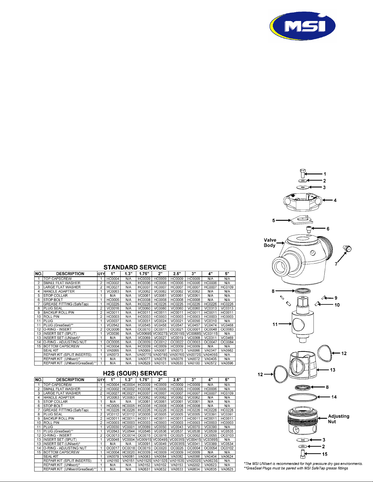
3. Lubricate the plug seal glands of the valve/adjusting nut with grease and install the plug seals (8) with the metal backup ring adjacent to the seal glands and facing away from the valve cavity.
4. Install the o-ring (14) onto the adjusting nut.
5. Apply a thin film of plug valve grease onto the primary sealing surface of the inserts (13) and install onto the adjusting nut. *Split
inserts are installed after the plug is inserted into the adjusting nut.
6. Apply a thin film of plug valve grease onto the large diameter of the plug (11) and carefully insert the lower end of the plug, opposite
the hex/keyway, down through the inserts (13) until it seats into the adjusting nut. *When using split inserts, the plug is seated into
the adjusting nut first. The inserts are then evenly spaced around the plug, hooking onto the adjusting nut.
7. Install the insert o-rings (12) by pressing them into the grooves of the inserts (13) with plug valve grease.
8. Tilt the subassembly and install the bottom capscrew (15) and washers (2)(3) through the bottom of the adjusting nut and into the
plug (11). *When using a GreaSeal® plug, the capscrew is replaced by a SafeTap® grease fitting and a 3/4” flat washer.
9. Apply anti-seize compound to the adjusting nut threads and o-ring area and lubricate the valve pocket below the threads with allpurpose grease.
11. Install the plug (11), inserts (13), and adjusting nut assembly into the valve body. Make sure that the roll pins (9)(10) in the body
are aligned with the slots of the inserts as you screw the subassembly into the adjusting nut.
12. Screw in the adjusting nut until proper alignment is obtained between the valve bore and the insert and plug. Do not tighten beyond
proper alignment. If sight through the bore is not possible, then screw in the adjusting nut until no more than one half of a thread or
no threads are visible.
13. Install the SafeTap® grease fitting (7) into the valve body plug using 50-60 ft-lbs of
torque. Teflon tape should not be used with SafeTap grease fittings since they do not
seal on the threads. See back page for more details on the SafeTap® grease fitting.
14. Install the stop bolt (6) and stop collar (5) if required.
15. Install the handle (4), top capscrew (1), and washers (2)(3) onto the top of the valve. If
the valve has an actuator or gear operator, bolt it back on the valve body and verify full
90° rotation. Adjust limit stops as necessary.
16. Remove excess grease from the valve bore and inspect plug alignment. Adjust as neces-
sary with adjusting nut.
17.
Grease the valve in the open position to approximately 3000psi, cycle once, and then
grease one more time. GreaSeal® plugs should be greased in the open position to pack
the valve cavity but may also be greased in the closed position prior to testing or while in
service. See back page for more details on GreaSeal® plugs.
LT Valve Parts List

Disassembly
1. Remove the top capscrew (1), washers (2)(3), handle (4), and
stop collar (5).
2. Secure the valve assembly with the adjusting nut facing up.
3. Using a bar, unscrew the adjusting nut counter-clockwise until
it disengages from the valve body. Leaving the bottom capscrew (15) in place will allow the entire internal assembly to be
removed from the valve at once.
4. Remove the bottom capscrew (15) and washers (2)(3).
5. Remove the plug (11) and inserts (13) from the adjusting nut.
6. Remove the insert o-rings (12), adjusting nut o-ring (14), and
plug seals (8).
7. Remove all grease and debris from all valve components.
8. Remove the grease fitting (7) from the body or plug (11).
Inspection and Repair
1. After degreasing the parts, visually inspect for wear, corrosion, or any other physical damage.
2. Inspect the primary sealing surface of the plug (11) and inserts (13) for any scratches or dings. Parts with heavy dings or deep
scratches in the sealing surfaces should be replaced. For light wear or superficial blemishes, use 600-grit sandpaper along with a
solvent to polish.
3. All surfaces which contact the elastomeric seals must be smooth and free of rust and pitting. Use sandpaper to polish. Parts with
excessive pitting and rust should be replaced.
4. Lubricate and screw the adjusting nut (without the o-ring) completely into the valve body to check for damaged threads. It should
turn easily all the way.
5. Check the roll pins (10) in the valve body by gently sliding a set of inserts (13) into the valve. The inserts should move freely up and
down the length of the roll pin slots without interference.
6. Inspect the grease fitting (7) for damaged threads or sealing surface.
SafeTap® Grease Fitting
SafeTap® grease fittings are design to provide maximize safe
operation in the field with these key features:
• The unique metal-to-metal seal eliminates wetted threads
and pipe taps. Since the threads do not perform a sealing
function they do not require Teflon tape or other sealing
aids.
• The heavier cross section stands up better to impacts.
• Each fitting has a slot machined through the threads which
serves as a pressure relief path in the event of a leak.
• The metal-to-metal seal and the pressure relief slot of the
SafeTap® grease fitting also allows a means to safely bleed
any residual internal pressure.
GreaSeal® Plug
The patented GreaSeal® plug is designed to provide maximum
lubrication in the harshest field conditions. Key features include:
• The only plug that
allows greasing in the
opened or closed position while in service.
• Dual 360° grease
channels
• Forces grease into
360° of the seal area
when closed.
• Allows for complete
distribution of lubricant
immediately prior to
opening a valve when
exposure to high temperatures and well
fluids may have compromised the existing
grease.
• Greasing in the closed
position can stop or
significantly slow
leaks in valves with
worn or damaged
parts.
MSI is a Division of Dixie Iron Works, Ltd.
300 West Main * Alice, Texas 78332 * USA
ph: 800.242.0059
ph: 361.664.6597
fax: 361.664.4840
email: sales@diwmsi.com
www.plugvalve.com
 Loading...