

Page 1
FCC-B Radio Frequency Interference Statement
This equipment has been tested an d fo und to comply with the limits for a class B digital device, pursuant to part 15 of
the FCC rules. These limits are designed to provide reasonable protection against harmful interference when the
equipment is operated in a commercial environment. This equipment generates, uses and can radiate radio frequency
energy and, if not installed and used in accordance with the instruction manual, may cause harmful interference to
radio communications. Operation of this equipment in a residential area is likely to cause harmful interference, in
which case the user will be required to correct the interference at his own expense.
Notice 1
The changes or modifications not expressly approved by the party responsible for compliance could void the user’s
authority to operate the equipment.
Notice 2
Shielded interface cables and A.C. power cord, if any, must be used in order to comply with the emission limits.
VOIR LA NOTICE D’NSTALLATION AVANT DE RACCORDER AU RESEAU.
Micro-Star International
MS-6712
This device complies with Part 15 of the FCC Rules. Operation is subject to the following two conditions:
(1) this device may not cause harmful interference, and
(2) this device must accept any interference received, including interference that may cause undesired operation
G52-M6712XH
i
Page 2

Copyright Notice
The material in this document is the intellectual property of MICRO-STAR INTERNATIONAL. We take every care in
the preparation of this document, but no guarantee is given as to the correctness of its contents. Our products are
under continual improvement and we reserve the right to make changes without notice.
Trademarks
All trademarks are the properties of their respective owners.
AMD, Athlon™ Athlon™XP, Thoroughbred™ and Duron™ are registered trademarks of AMD Corporation.
Intel® and Pentium® are regist er ed tra dem arks of Intel Corporation.
PS/2 and OS® 2 are registered trademarks of International Business Machines Corporation.
Microsoft® is a registered trademark of Microsoft Corporation. Windows® 98/2000/NT/XP are registered trademarks
of Microsoft Corporation.
NVIDIA, the NVIDIA logo, DualNet, and nForce are registered trademarks or trademarks of NVIDIA Corporation in the
United States and/or other countries.
Netware® is a registered trademark of Novell, Inc.
Award® is a registered trademark of Phoenix Technologies Ltd.
AMI® is a registered trademark of American Megatrends Inc.
Kensington and MicroSaver are registered trademarks of the Kensington Technology Group.
PCMCIA and CardBus are registered trademarks of the Personal Computer Memory Card International Association.
Revision History
Revision Revision History Date
V1.0 First release of multi-lingual version for PCB 1.x May 2004
With VIA KT400 & VT8235 chipsets
ii
Page 3

Safety Instructions
1. Always read the safety instructions carefully .
2. Keep this User Manual for future refere nce.
3. Keep this equipment away from humidit y.
4. Lay this equipment on a reliable flat surface before setting it up.
5. The openings on the enclosure are for air convection hence protects the equipment from overheating. Do not
cover the openings.
6. Make sure the voltage of the power source and adjust properly 110/220V before connecting the equipment to the
power inlet.
7. Place the power cord such a way that people can not step on it. Do not place anything over the power cord.
8. Always Unplug the Power Cord before inserting any add-on card or module.
9. All cautions and warnings on the equipment should be noted.
10. Never pour any liquid into the opening that could damage or cause electrical shock.
11. If any of the following situations arises, get the equipment checked by a service personnel:
- The power cord or plug is damaged.
- Liquid has penetrated into the equipment.
- The equipment has been exposed to moi stur e.
- The equipment does not work well or you can not get it work according to User Manual.
- The equipment has dropped and damaged.
- The equipment has obvious sign of breakage.
12. Do not leave this equipment in an environment unconditioned, storage temperature above 60° C (140°F), it may
damage the equipment.
CAUTION: Danger of explosion if battery is incorrectly replaced. Replace only with
the same or equivalent type recommended by the manufacturer.
iii
Page 4

Table of Content
English.....................................................................1
Deutsch....................................................................15
Français...................................................................29
简体中文...................................................................43
繁體中文...................................................................57
iv
Page 5

Introduction
Thank you for purchasing the KT4-V Series (MS-6712 v1.X) ATX mainboard. The KT4-V Series is
based on VIA ® KT400 & VT8235 chipsets for optimal system efficiency. Designed to fit the advanced
AMD® Athlon/Athlon XP/Duron processors in 462 pin package, the KT4-V Series delivers a high
performance and professional desktop platform solution.
Specifications
CPU
l Supports AMD ® Athlon / Athlon XP / Duron (Socket 462) processor
l Supports from 1100MHz up to 2800+ or above
(For the latest information about CPU, please visit
http://www.msi.com.tw/program/products/mainboard/mbd/pro_mbd_cpu_support.php )
Chipset
l VIA ® KT400 chipset
- Supports 200/266/333MHz front side bus
- Supports DDR200/266/333/400*
- Supports AGP 4X/8X
l VIA ® VT8235 chipset
- Integrated Direct Sound AC97 audio
- Dual channel Ultra DMA 33/66/100/133 master mode EIDE controller
- ACPI & PC2001 compliant enhanced power management
- Integrated USB 2.0 controller
Main Memory
l Supports six memory banks using three 184-pin DDR DIMMs.
l Supports up to 3GB PC1600/2100/2700/3200* DDR SDRAMs.
l Supports 2.5v DDR SDRAM.
(*For the updated supporting memory modules, please visit
http://www.msi.com.tw/program/products/mainboard/mbd/pro_mbd_trp_list.php )
Slots
l One AGP (Accelerated Graphics Port) 4x/8x slot.
l Six PCI 2.2 32-bit PCI bus slots (support 3.3v/5v PCI bus interface).
1
Page 6

l One CNR (Communication Network Riser) slot.
Onboard IDE
l An IDE controller integrated in the VIA® VT8235 chipset
- Supports IDE HDD/CD-ROM with PIO, Bus Master and Ultra DMA 66/100/133 operation
modes
- Can connect up to four Ultra ATA drives
On-Board Peripherals
l On-Board Peripherals include:
- 1 floppy port supports 2 FDDs with 360K, 720K, 1.2M, 1.44M and 2.88Mbytes
- 2 serial ports
- 1 parallel port supports SPP/EPP/ECP mode
- 6 USB 2.0 ports (Rear x 4 / Front x 2)
- vertical audio ports
- 1 SPDIF output (2 x 6 pin) with housing (optional)
- 1 S-Bracket (optional)
- 1 D-Bracket 2 (optional)
Audio
l Realtek ALC650 6-channel audio
LAN
l VIA® VT6103 LAN controller
BIOS
l The mainboard BIOS provides Plug & Play BIOS which detects the peripheral devices and
expansion cards of the board automatically
l The mainboard provides a Desktop Management Interface (DMI) function which records your
mainboard specifications
Dimension
l ATX Form Factor: 30.5cm x 21cm
Mounting
l 6 standard mounting holes
Others
l Supports WOL/WOR
l Suspend to RAM/Disk (S3/S4)
2
Page 7
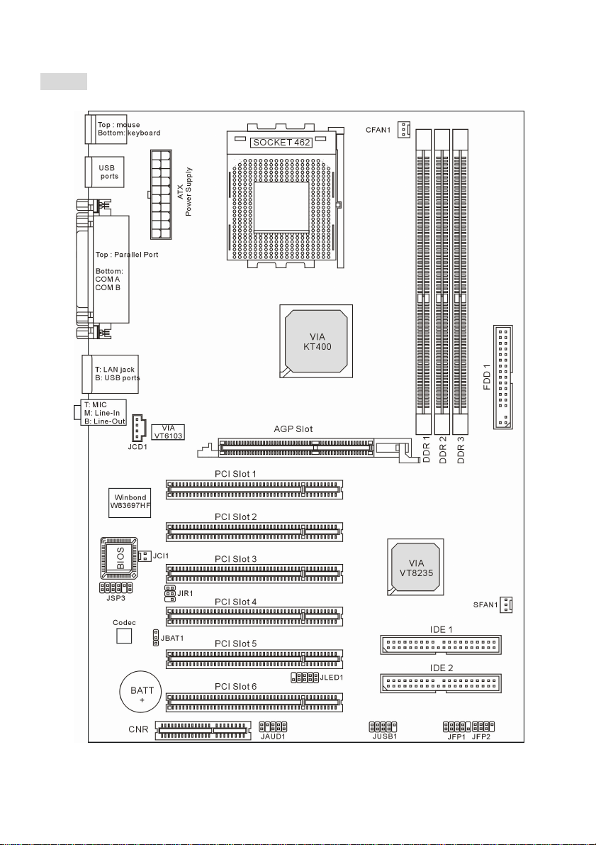
Layout
3
Page 8

KT4-V (MS-6712 v1.X) ATX Mainboard
4
Page 9
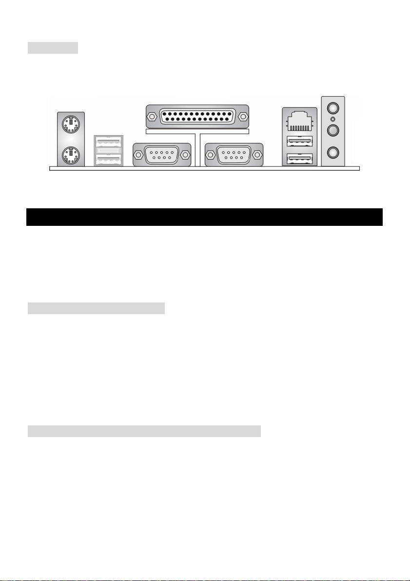
Rear Panel
The back panel provides the following connectors:
Mouse Parallel
Keyboard
COM A
COM B
LAN
USBUSB
MIC
L-in
L-out
Hardware Setup
This chapter tells you how to install the CPU, memory modules, and expansion cards, as well as how to
setup the jumpers on the mainboard. It also provides the instructions on connecting the peripheral
devices, such as the mouse, keyboard, etc. While doing the installation, be careful in holding the
components and follow the installation procedures.
Central Processing Unit: CPU
The mainboard supports AMD Athlon, Athlon XP and Duron processors in the 462 pin package. The
mainboard uses a CPU socket called Socket A for easy CPU installation. When you are installing the
CPU, make sure the CPU has a heat sink and a cooling fan attached on the top to prevent overheating.
If you do not find the heat sink and cooling fan, contact your dealer to purchase and install them before
turning on the computer. (For the latest information about CPU, please visit
http://www.msi.com.tw/program/products/mainboard/mbd/pro_mbd_cpu_support.php )
Example of CPU Core Speed Derivation Procedure
If CPU Clock = 100MHz
Core/Bus ratio = 14
then CPU core speed = Host Clock x Core/Bus ratio
= 100MHz x 14
= 1.4 GHz
5
Page 10

Memory Speed/CPU FSB Support Matrix
FSB
Memory
200 MHz YES YES NO
266 MHz YES YES
333 MHz NO YES
400 MHz NO NO
△: User may try this combination, but MSI will not guarantee its functionality.
*: For the updated supporting memory modules, please visit
http://www.msi.com.tw/program/products/mainboard/mbd/pro_mbd_trp_list.php
DDR 266 DDR333 DDR 400
YES*
△
YES*
CPU Installation Procedures for Socket 462
1. Please turn off the power and unplug the power cord before installing the CPU.
2. Pull the lever sideways away from the socket. Make sure to raise the lever up to a 90 -degree angle.
3. Look for the gold arrow. The gold arrow should point towards the lever pivot. The CPU can only fit
in the correct orientation.
4. If the CPU is correctly installed, the pins should be completely embedded into the socket and can
not be seen. Please note that any violation of the correct installation procedures may cause
permanent damages to your mainboard.
5. Press the CPU down firmly into the socket and close the lever. As the CPU is likely to move while
the lever is being closed, always close the lever with your fingers pressing tightly on top of the CPU
to make sure the CPU is properly and completely embedded into the socket.
Installing the CPU Fan
As processor technology pushes to faster speeds and higher performance, thermal management
becomes increasingly important. To dissipate heat, you need to attach the CPU cooling fan and
heatsink on top of the CPU. The following instructions will guide you through the heat sink installation
procedures. Please consult your agent for the proper CPU cooler set.
1. Position your CPU cooler set onto the CPU.
2. Use one end of the clip to hook the latch of the CPU sliding plate.
3. Hook the other latch to fix the cooling fan set. You may need a screw driver to press down the
6
Page 11
other side of the clip. Connect the fan to the power supply connector provided on your mainboard.
MSI Reminds You...
Overheating
Overheating will seriously damage the CPU and system, always make sure the cooling fan can work
properly to protect the CPU from overheating.
Replacing the CPU
While replacing the CPU, always turn off the ATX power supply or unplug the power supply’s power
cord from grounded outlet first to ensure the safety of CPU.
Memory
The mainboard provides 3 slots for 184-pin DDR SDRAM DIMM (Double In-Line Memory Module)
modules and supports the memory size up to 3GB. Install at least one DIMM module on the slots.
Each DIMM slot supports up to a maximum size of 1GB. You can install either single- or double-sided
modules to meet your own needs.
Please refer to http://www.msi.com.tw/program/products/mainboard/mbd/pro_mbd_trp_list.php for
compatible DDR modules.
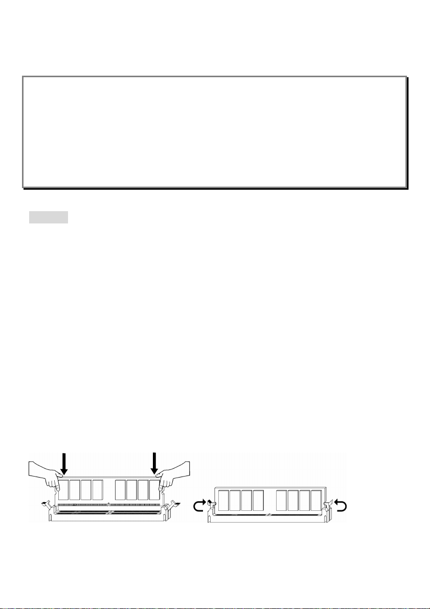
Installing DDR Modules
1. The DDR DIMM has only one notch on the center of module. The module will only fit in the right
orientation.
2. Insert the DIMM memory module vertically into the DIMM slot. Then push it in until the golden finger
on the memory module is deeply inserted in the socket.
3. The plastic clip at each side of the DIMM slot will automatically close.
7
Page 12
Power Supply
The mainboard supports ATX power supply for the power system. Before inserting the power supply
connector, always make sure that all components are installed properly to ensure that no damage will
be caused. Power supplies of 300watt (and up) are highly recommended for system stability.
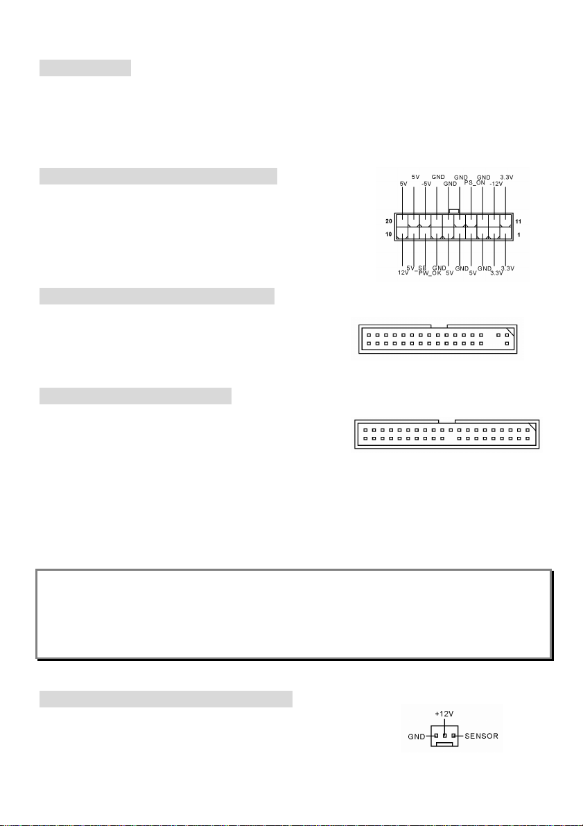
ATX 20-Pin Power Connector: JWR1
This connector allows you to connect to an ATX power supply. To
connect to the ATX power supply, make sure the plug of the power
supply is inserted in the proper orientation and the pins are aligned.
Then push down the power supply firmly into the connector.
Floppy Disk Drive Connector: FDD1
The mainboard provides a standard floppy disk drive
connector that supports 360K, 720K, 1.2M, 1.44M and 2.88M
floppy disk types.
IDE Connectors: IDE1 & IDE2
The mainboard has a 32-bit Enhanced PCI IDE and Ultra
DMA 33/66/100/133 controller that provides PIO mode 0~4,
Bus Master, and Ultra DMA 33/66/100/133 function. You can
connect up to four hard disk drives, CD-ROM, 120MB Floppy and other devices.
The first hard drive should always be connected to IDE1. IDE1 can connect a Master and a Slave drive.
You must configure second hard drive to Slave mode by setting the jumper accordingly. IDE2 can also
connect a Master and a Slave drive.
MSI Reminds You...
If you install two hard disks on cable, you must configure the second drive to Slave mode by setting its
jumper. Refer to the hard disk documentation supplied by hard disk vendors for jumper setting
instructions.
Fan Power Connectors: CFAN1/SFAN1
The CFAN1 (processor fan) and SFAN1 (system fan) support system
cooling fan with +12V. They support three-pin head connector. When
8
Page 13
connecting the wire to the connectors, always note that the red wire is the positive and should be
connected to the +12V, the black wire is Ground and should be connected to GND. If the mainboard
has a System Hardware Monitor chipset on-board, you must use a specially designed fan with speed
sensor to take advantage of the CPU fan control.
MSI Reminds You...
Always consult the vendors for proper CPU cooling fan.
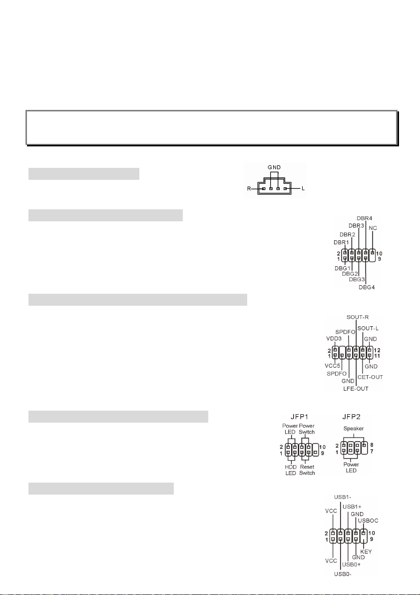
CD-In Connector: JCD1
The connector is for CD-ROM audio connector.
D-Bracket
The mainboard comes with a JLED1 connector for you to connect to D-Bracket® 2.
D-Bracket® 2 is a USB Bracket that supports both USB1.1 & 2.0 spec. It integrates
four LEDs and allows users to identify system problems through 16 various
combinations of LED signals.
®
2 Connector: JLED1
S-Bracket (SPDIF) Connector: JSP3 (Optional)
The connector allows you to connect an S-Bracket for Sony & Philips Digital
Interface (SPDIF). The S-Bracket offers 2 SPDIF jacks for digital audio
transmission (one for optical fiber connection and the other for coaxial), and 2
analog Line-Out jacks for 4-channel audio output.
To attach the fiber-optic cable to optical SPDIF jack, you need to remove the plug
from the jack first. The two SPDIF jacks support SPDIF output only.
Front Panel Connectors: JFP1 & JFP2
The mainboard provides two front panel connectors for electrical
connection to the front panel switches and LEDs. The JFP1 is
compliant with Intel Front Panel I/O Connectivity Design Guide.
Front USB Connector: JUSB1
The mainboard provides one USB 2.0 pin header JUSB1 that is compliant with
Intel® I/O Connectivity Design Guide. USB 2.0 technology increases data transfer
rate up to a maximum throughput of 480Mbps, which is 40 times faster than USB
9
Page 14
1.1, and is ideal for connecting high-speed USB interface peripherals such as USB HDD, digital
cameras, MP3 players, printers, modems and the like.
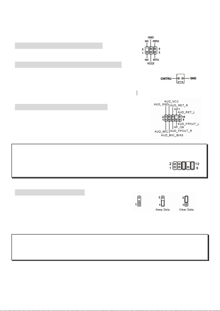
IrDA Infrared Module Header: JIR1
The connector allows you to connect to IrDA Infrared module.
Chassis Intrusion Switch Connector: JCI1
This connector is connected to 2-pin connector chassis switch. If the Chassis
is open, the switch will be short. The system will record this status. To clear
the warning, you must enter the BIOS setting and clear the status.
Front Panel Audio Connector: JAUD1
The front panel audio connector allows you to connect to the front panel
audio and is compliant with Intel® Front Panel I/O Connectivity Design
Guide.
MSI Reminds You...
If you do not want to connect to the front audio header, pins 5 & 6, 9 & 10 have to
be jumpered in order to have signal output directed to the rear audio ports.
Otherwise, the Line-Out connector on the back panel will not function.
Clear CMOS Jumper: JBAT1
There is a CMOS RAM on board that has a power supply
from external battery to keep the data of system configuration.
With the CMOS RAM, the system can automatically boot OS every time it is turned on. If you want to
clear the system configuration, use the JBAT1 (Clear CMOS Jumper) to clear data.
MSI Reminds You...
You can clear CMOS by shorting 2-3 pin while the system is off. Then return to 1-2 pin position. Avoid
clearing the CMOS while the system is on; it will damage the mainboard.
The mainboard provides one AGP slot, six 32-bit PCI bus slots and one CNR slot.
10
Page 15
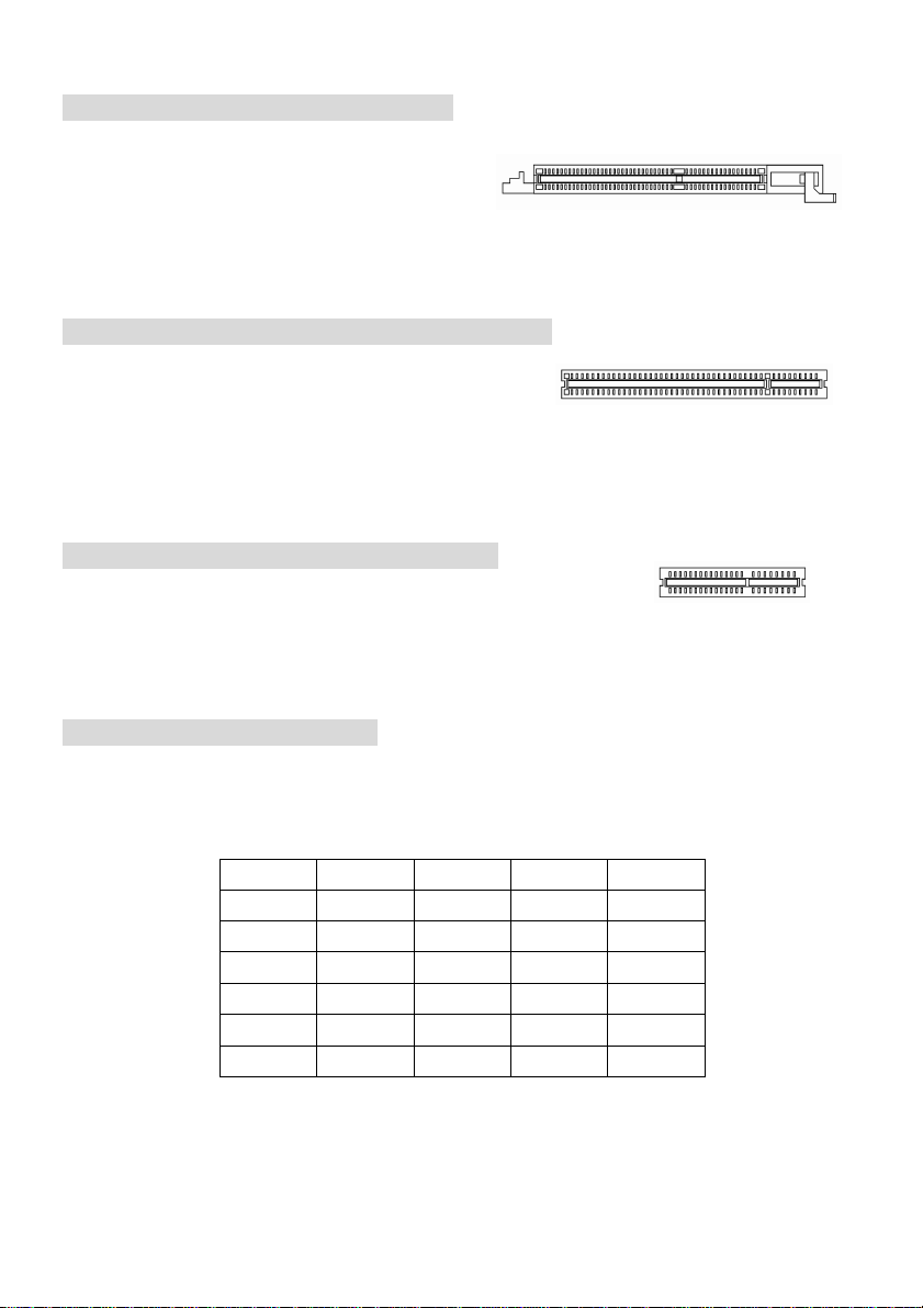
AGP (Accelerated Graphics Port) Slot
The AGP slot allows you to insert the AGP graphics
card. AGP is an interface specification designed for
the throughput demands of 3D graphics. It introduces
a 66MHz, 32-bit channel for the graphics controller to directly access main memory. The slot supports
8x/4x AGP card.
PCI (Peripheral Component Interconnect) Slots
The PCI slots allow you to insert the expansion cards to meet
your needs. When adding or removing expansion cards,
make sure that you unplug the power supply first. Meanwhile, read the documentation for the
expansion card to make any necessary hardware or software settings for the expansion card, such as
jumpers, switches or BIOS configuration.
CNR (Communication Network Riser) Slot
The CNR slot allows you to insert the CNR expansion cards. CNR is a
specially designed network, audio, or modem riser card for ATX family motherboards. Its main
processing is done through software and controlled by the motherboard chipset.
PCI Interrupt Request Routing
The IRQ, acronym of interrupt request line and pronounced I-R-Q, are hardware lines over which
devices can send interrupt signals to the microprocessor. The PCI IRQ pins are typically connected to
the PCI bus INT A# ~ INT D# pins as follows:
Order 1 Order 2 Order 3 Order 4
PCI Slot 1 INT A# INT B# INT C# INT D#
PCI Slot 2 INT B# INT C# INT D# INT A#
PCI Slot 3 INT C# INT D# INT A# INT B#
PCI Slot 4 INT D# INT A# INT B# INT C#
PCI Slot 5 INT B# INT C# INT D# INT A#
PCI Slot 6 INT C# INT D# INT A# INT B#
11
Page 16

12
Page 17
BIOS Setup
Power on the computer and the system will start POST (Power On Self Test) process. When the
message below appears on the screen, press <DEL> key to enter Setup.
DEL: Setup F11: Boot Menu F12: Network boot TAB: Logo
If the message disappears before you respond and you still wish to enter Setup, restart the system by
turning it OFF and On or pressing the RESET button. You may also restart the system by
simultaneously pressing <Ctrl>, <Alt>, and <Delete> keys.
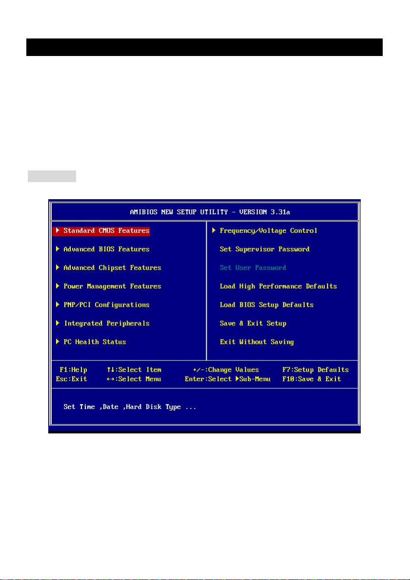
Main Page
Standard CMOS Features
Use this menu for basic system configurations, such as time, date etc.
Advanced BIOS Features
Use this menu to setup the items of AMI special enhanced features.
Advanced Chipset Features
Use this menu to change the values in the chipset registers and optimize your system performance.
Power Management Features
13
Page 18
Use this menu to specify your settings for power management.
PNP/PCI Configurations
This entry appears if your system supports PnP/PCI.
Integrated Peripherals
Use this menu to specify your settings for integrated peripherals.
PC Health Status
This entry shows your PC health status.
Frequency/Voltage Control
Use this menu to specify your settings for frequency/voltage control.
Load High Performance Defaults
Use this menu to load the BIOS values for the best system performance, but the system stability may
be affected.
Load BIOS Setup Defaults
Use this menu to load the factory default settings for optimal & stable system performance.
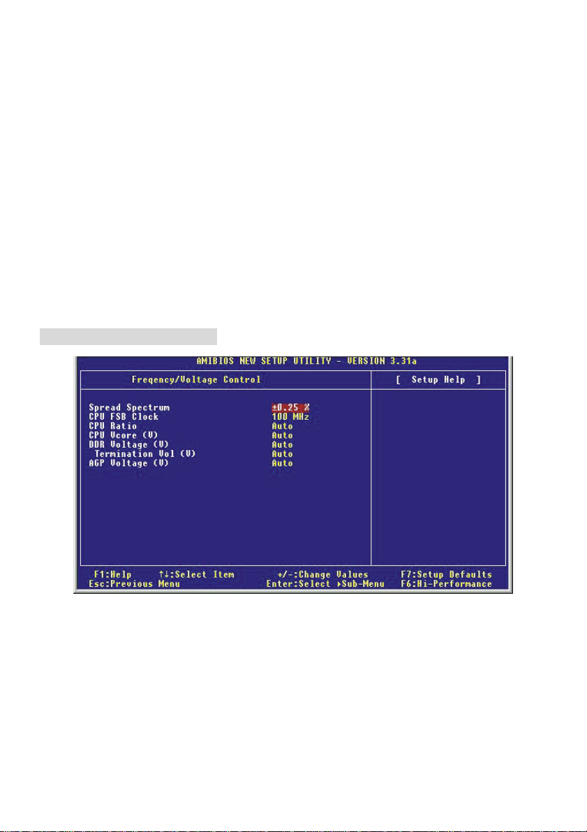
Frequency/Voltage Control
Spread Spectrum
When the motherboard clock generator pulses, the extreme values (spikes) of the pulses creates EMI
(Electromagnetic Interference). The Spread Spectrum function reduces the EMI generated by
modulating the pulses so that the spikes of the pulses are reduced to flatter curves. If you do not have
any EMI problem, leave the setting at [Disabled] for optimal system stability and performance. But if you
are plagued by EMI, set to [Enabled] for EMI reduction. Remember to disable Spread Spectrum if you
are overclocking because even a slight jitter can introduce a temporary boost in clock speed which may
just cause your overclocked processor to lock up.
14
Page 19

CPU FSB Clock
This item allows you to select the CPU Front Side Bus clock frequency (in MHz) and overclock the
processor by adjusting the FSB clock to a higher frequency.
CPU Ratio/Vcore (V)
The settings are used to adjust the CPU clock multiplier (ratio) and CPU core voltage (Vcore). These
settings offer users a tool to overclock the system.
DDR Voltage Adjust (V)
Adjusting the DDR voltage can increase the DDR speed. Any changes made to this setting may
cause a stability issue, so changing the DDR voltage for long-term purpose is not recommended.
Termination Vol (V)
This item is used to adjust the termination voltage.
AGP Voltage Adjust (V)
AGP voltage is adjustable in the field, allowing you to increase the performance of your AGP display
card when overclocking, but the stability may be affected.
For complete BIOS setup information, please visit MSI website at http://www.msi.com.tw.
15
Page 20

NOTE
16
Page 21

15
Introduction
Vielen Dank für die Wahl des KT4-V Serie (MS-6712 v1.X) ATX Mainboard. Die KT4-V Serie basiert
auf dem VIA ® KT400 & VT8235 Chipsatz für optimale Systemeffizienz. Entwickelt für die
fortgeschrittenen AMD® Athlon/Athlon XP/Duron Prozessoren im 462 Pin Gehäuse, bietet die KT4-V
Serie hohe Performance und eine professionelle Desktop Lösung.
Spezifikationen
CPU
l Unterstutzt AMD ® Athlon / Athlon XP / Duron (Socket 462) Prozessor
l Unterstützt von 1100MHz bis zu 2800+ oder höheren Takt
(Die neuesten Informationen zur Prozessorunterstützung finden Sie auf
http://www.msi.com.tw/program/products/Mainboard/mbd/pro_mbd_cpu_unterstützt.php )
Chipsatz
l VIA ® KT400 Chipsatz
- Unterstützt 200/266/333MHz Front Side Bus
- Unterstützt DDR 200/266/333/400*
- Unterstützt AGP 4X/8X
l VIA ® VT8235 Chipsatz
- Integrierter Direct Sound AC97 Audio Kontroller
- Zweikanal Ultra DMA 33/66/100/133 Master Modus EIDE Kontroller
- ACPI & PC2001 compliant enhanced power management
- Integrated USB 2.0 Kontroller
Main Memory
l Unterstützt six memory banks using three 184-Pin DDR DIMMs.
l Unterstützt bis zu 3GB PC1600/2100/2700/3200* DDR SDRAMs.
l Unterstützt 2.5v DDR SDRAM.
(*Dieneuesten Informationen zur Speicherunterstützung finden Sie auf
http://www.msi.com.tw/program/products/Mainboard/mbd/pro_mbd_trp_list.php )
Steckplätze
l Ein AGP (Accelerated Graphics Anschluß) 4x/8x Steckplatz.
l Sechs PCI 2.2 32-bit PCI Bus Steckplätze (unterstützt 3.3v/5v PCI Bus Schnittstelle).
l Ein CNR (Communication Network Riser) Steckplatz.
Onboard IDE
l Ein IDE Kontroller integriert in den VIA® VT8235 Chipsatz
- Unterstützt IDE HDD/CD-ROM mit PIO, Bus Master und Ultra DMA 66/100/133
Operationsmodus
Page 22

16
- Unterstützt bis zu vier Ultra ATA Laufwerke
On-Board Peripherals
l On-Board Peripherie:
- 1 Floppy Anschluß unterstützt 2 FDDs mit 360K, 720K, 1.2M, 1.44M und 2.88Mbytes
- 2 serielle Anschlüsse
- 1 paralleler Anschluß unterstützt SPP/EPP/ECP Modus
- 6 USB 2.0 Anschluß (Rückseitig x 4 / Front x 2)
- Vertikal angeordnete Audio-Anschlüsse
- 1 SPDIF Ausgang (2 x 6 Pin) (optional)
- 1 S-Bracket (optional)
- 1 D-Bracket 2 (optional)
Audio
l Realtek ALC650 6-Kanal Audio
LAN
l VIA® VT6103 LAN Kontroller
BIOS
l Das Mainboard BIOS stellt ein Plug & Play BIOS zur Verfügung, welches Peripherie Geräte und
Erweiterungskarten automatiasch erkennt und konfiguriert.
l Das Mainboard hat eine Desktop Management Interface (DMI) Funktion, welche die
Mainboardkonfiguration protokolliert.
Größe
l ATX Form Faktor: 30.5cm x 21cm
Befestigung
l 6 Befestigungslöcher
Others
l Unterstutzt WOL/WOR
l Unterstützt Suspend to RAM/Disk (S3/S4)
Page 23

17
Layout
KT4-
V
(MS6712
v1.X)
ATX
Main
boar
d
Page 24

18
Rückseitige Anschlüsse
Die Rückseite des Mainboards hat folgende Anschlußmöglichkeiten:
Mouse Parallel
Keyboard USB
COM A
COM B
LAN
USB
MIC
L-in
L-out
Hardware Setup
Dieses Kapitel beschreibt Ihnen, wie CPU, Speichermodule und Erweiterungskarten eingesetzt werden,
und wie Jumper auf dem Mainboard eingestellt werden. Es beinhaltet auch die Anleitung, wie Sie
Peripheriegeräte wie Maus, Tastatur, usw. anschließen. Während der Installation behandeln Sie bitte
die Komponenten vorsichtig und folgen Sie genau der Anleitung.
Central Processing Unit: CPU
Das Mainboard unterstützt AMD ® AthlonTM/AthlonTM XP/DuronTM Prozessoren im Sockel 462 Format.
Das Mainboard hat dafür einen CPU Sockel, der auch Sockel A genannt wird, und die Installation der
CPU vereinfacht. Wenn Sie die CPU installieren, stellen Sie sicher, dass Sie einen geeigneten
CPU-Kühler aufsetzen, um die CPU vor Beschädigung durch Überhitzung zu schützen. Wenn
Sie keinen passenden CPU-Kühler haben, konatkieren Sie Ihren Händler um ein geeignetes Modell zu
beziehen. Schlaten Sie den PC nicht ein, bevor Sie einen geeigneten Kühler installiert wurde. (Für die
neuesten CPU-Kompatiblitäts- Informationen besuchen Sie bitte die folgende Webseite:
http://www.msi.com.tw/program/products/mainboard/mbd/pro_mbd_cpu_support.php )
Beispiel für die Einstellung des internen CPU-Taktes
Wenn CPU externer Takt = 100MHz
Taktmultiplikator = 14
dann CPU Kerntakt = Externer Takt x Taktmultiplikator
= 100MHz x 14 = 1.4GHz
Page 25

19
Speichergeschwindigkeit- / CPU FSB Unterstützungstabelle
Speicher
FSB
200 MHz Ja Ja Nein
266 MHz Ja Ja Ja*
333 MHz Nein Ja △
400 MHz Nein Nein Ja*
△: Sie können diese Kombination ausprobieren, aber MSI kann die Funktion nicht garantieren .
*: Für die neuesten Speicher-Kompatiblitäts-Informationen besuchen Sie bitte die folgende
Webseite: http://www.msi.com.tw/program/products/mainboard/mbd/pro_mbd_trp_list.php
DDR 266 DDR333 DDR 400
Installation der CPU im Sockel 462
1. Bitte schalten Sie den Computer aus und trennen ihn von der Netzspannung, bevor Sie die CPU
einsetzen.
2. Klappen Sie den seitlichen Hebel im 90° Winkel nach Oben.
3. Die dreieckige Markierung auf dem Prozessor muss so ausgerichtet werden, dass sie wie ein
Pfeil auf das Lager des Verriegelungshebel zeigt. Nur in dieser Richtung passt der Prozessor in
den Sockel.
4. Wenn die CPU richtig eingesetzt wurde, sind die Anschlüsse der CPU komplett in den Sockel
versunken und könnne nicht mehr gesehen werden, Bitte beachten Sie, dass beim falschen
Eisetzen der CPU in den Sockel das Mainboard und die CPU zerstört werden können!
5. Drücken Sie nochmal auf die CPU und klappen dabei den Hebel wieder herunter, bis er einrastet.
Dabei bewegt sich die CPU noch etwas in ihre endgültige Position.
Installation des CPU Lüfters
Die nachfolgende Anleitung wird Ihnen bei der Installation des CPU-Kühlers helfen. Bitte beachten Sie,
dass Sie einen für Ihre CPU freigegebenen Kühler verwende.n Um dies zu überprpüfen, konnen Sie
auf der Webseite www.amd.de und beim Hersteller des Kühlers nachsehen. Schauen Sie auch in der
Dokumentation des Kühlers nach, ob etwas spezielles bei der Montage dieses Kühlers zu beachten ist!
1. Setzen Sie den Kühler vorsichtig und gerade auf die CPU. Beachten Sie dabei, dass die
Untersiete des Kühlers am Rand eine Treppenstufe hat. Diese muss über der Achse des
Befestigungshebels am Sockel positioniert werden. Setzen Sie den Kühler keinesfalls
andersherum auf.
2. Haken Sie eine Öse der Befestigungsfeder des Kühlers an der Nase des Prozessorsockels
ein.
3. Drücken Sie die Befestigungsfeder nun auf der anderen Seite vorsichtig herunter, bis auch
deren Öse an der Haltenase einrastet. Bitte dabei keine Gewalt anwenden, und falls Sie
dazu Werkzeug benutzen, passen Sie auf, dass Sie nicht von der Befestigungsfeder
Page 26

20
abrutschen und dabei das Mainboard beschädigen.
4. Schliessen Sie den Stecker des Prozessorkühlers an den Anschluss FANCPU1 des
Mainboards an.
MSI erinnert Sie...
Überhitzung…
Überhitzung beschädigt Ihre CPU und ds gesamte System ernsthaft, stellen Sie daher sicher, dass die
Lüfter immer funktionieren, um die CPU und das System vor Schäden zu bewahren.
Die CPU tauschen…
Wenn Sie die CPU tauschen, schalten Sie das System ab und ziehen den Netzstecker. Bevor Sie das
Mainboard oder die CPU anfassen, erden Sie sich, in dem Sie kurz geerdeten Gegenstand (z.B.
Heizung) berühren. Dadurch vermeiden Sie Defekte an der Hardware durch statische Aufladung.
Speicher
Das Mainboard stellt zwei 184-Pin ungepufferte DDR200/DDR266/DDR333 DDR SDRAM Sockel zur
verfügung, und unterstützt eine maximale Speichergröße von bis zu 2GB. . Damit das System
funktioniert, muss wenigstens ein DIMM eingesetzt werden.
(Für die neuesten Speicher-Kompatiblitäts-Informationen besuchen Sie bitte die folgende Webseite:
http://www.msi.com.tw/program/products/mainboard/mbd/pro_mbd_trp_list.php )
Speichermodule können in beliebiger Reihenfolge installiert werden. Sie können sowohl einseitige als
auch zweiseitige Module verwenden.
DDR Modules einsetzen
1. Das DDR DIMM Modul hat in der Mitte eine Nase, die verhindern soll, dass Sie das Modul in der
falschen Richtung einsetzen.
2. Setzen Sie das Modul senkrecht in den Sockel ein, bis die goldenen Kontakte komplett im Sockel
versinken.
3. Die weißen Verriegelungshebel an der Seite schließen sich automatisch und rasten ein.
Page 27

21
Netzteil
Das Mainboard unterstützt ATX Netzteile für die Stromversorgung. Befor Sie das System einschalten,
vergewissern Sie sich, dass alle Komponenten richtig eingesetzt wurden, damit das Sys tem nicht
beschädigt werden kann.. Ein Netzteil mit 300W oder mehr wird empfohlen.
ATX 20-Pin Power Anschluß: JWR1
An diesem Anschluss schließen Sie das Netzteil an. Der
Netzteilstecker lässt sich nur in einer Richtung einstecken.
Drücken Sie den Stecker in den Anschluss, bis er einrastet.
Floppy Disk Drive Connector: FDD1
Das Mainboard stellt einen Floppyanschluss zur Verfügung, an
dem bis zu zwei Lauf werke mit 360K, 720K, 1.2M, 1.44M und
2.88M Kapazität angeschlossen werden können.
IDE Anschlüsse: IDE1 & IDE2
Das Mainboard hat einen 32-bit erweiterten PCI IDE und
Ultra DMA 33/66/100/133 Controller, welcher die PIO
Modis 0~4, Bus Master, und Ultra DMA 33/66/100/133
Funktion zur Verfügung stellt. Sie können bis zu vier IDE-Festplatten, CD-ROM, 120MB Floppys und
andere Geräte anschließen.
MSI erinnert Sie...
Wenn Sie zwei IDE-Laufwerke an einem IDE-Kabel anschließen, so müssen Sie das erste Laufwerk
als Master und das zweite Laufwerk als Slave konfigurieren. Sie erfahren aus der Dokumentation der
Laufwerke, wie diese Einstellung gemacht wird.
Fan Power Connectors: CFAN1/SFAN1
Der CFAN1 (Prozessor Lüfter) und SFAN1 (System Lüfter) unterstützen
Lüfter mit +12V Betriebsspannung. Diese müssen einen dreipoligen
Anschluss haben. Beim Anschliessen beachten, dass das rote Kabel im Stecker immer mit dem
12-Anschluss des Steckers, der schwarze mit Masse des Steckers verbunden wird. Da das Mainboard
mit Hardware monitor ausgestattet ist, müsen Sie spezielle Lüfter mit Speed-Signal verwenden, damit
die Lüftergeschwindigkeit ausgewertet und gesteuert werden kann .
MSI erinnert Sie...
Bitte immer die Hinweise des Prozessorherstellers für die richtige Wahl des CPU-Lüfters beachten.
Page 28

22
CD-In Connector: JCD1
Hier können Sie das Audiokabel Ihres CD-Laufwerks anschließen.
D-Bracket
Das Mainboard hat einen JLED1 Anschluß, wo Sie das D-Bracket® 2.
D-Bracket® 2 anschließen können, welches auch USB USB1.1 & 2.0
Anschlüsse bietet. Die D-LEDs geben Ihnen bei Problemen beim Systemstart
Aufschluß über mögliche Fehlerquellen durch 16 verschiedene
Fabrkombinationen der LEDs.
®
2 Anschluß: JLED1
S-Bracket (SPDIF) Anschluß: JSP3 (Optional)
Dieser Anschluß erlaubt Ihnen den Anschluß des S-Bracket für Sony & Philips
Digital Interface (SPDIF). Das S-Bracket hat dafür 2 SPDIF Buchsen für digitale
Audio Übertragung (eine für optische Verbindungen und der Andere für
coaxial/elektrisch). Zusätzlich sind zwei analoge Line-Out Buchsen für 4-Kanal
Audio Ausgabe vorhanden. Um ein optisches Kabel an SPDIF anzuschliessen,
müssen Sie den Schutzstecker vom S-Bracket entfernen. Beide
SPDIS-Anschlüsse sind nur Ausgänge..
Gehäusefront-Anschlüsse: JFP1 & JFP2
Das Mainboard hat Anschlüsse für Bedienelemente und
Statusanzeigen an der Vorderseite des gehäuses. Hierzu gehören
Anzeige LEDs und Taster. JFP1 entspricht dem “Intel Front Panel I/O
Connectivity Design Guide”.
Gehäusefront USB Anschluss: JUSB1
Das Mainboard stellt einen Standard USB 2.0 Anschluss zur Verfügung JUSB1.
USB 2.0 Technologie bietet eine erhöhte Datentransferrate von maximal 480Mbps,
was 40 mal so schnell wie USB 1.1 ist, und ist ideal, um
Hochgeschwindkeits-USB-Geräte anzuschließen.
IrDA Infrarot Modul Anschluß: JIR1
Dieser Anschluß erlaubt den Anschluß eines IrDA Infrar ot Moduls.
Chassis Intrusion Sensor Anschluss: JCI1 (Optional)
Diesen Anschluss kann für einen zweipoligen Chassis Intrusion Sensor
verwendet werden. Wenn das Gehäuse offen ist, dann ist der Schalter geschlossen. Das Mainboard
zeichnet diesen Status auf. Um die Warnmeldung zu löschen, müssen Sie in das BIOS und dort den
Status zurücksetzen.
Page 29

23
Gehäusefront Audio-Anschluss: JAUD1
Der JAUD1 Gehäusefront-Anschluss erlaubt es Ihnen,
Audio-Anschlüsse an der Vorderseite Ihres Gehäuses mit dem
Mainboard zu verbinden. Der Anschluss entspricht dem “Intel ®
Front Panel I/O Connectivity Design Guide”
MSI erinnert Sie...
Wenn Sie diesen Audioanschluss nicht verwenden möchten, so müssen die
Kontakte 5 & 6, 9 & 10 jeweils mit einem Jumper geschlossen sein, damit
der hintere Audio-Ausgang des Mainboards funktioniert..
CMOS Rücksetz-Jumper: JBAT1
Im Mainboard ist ein CMOS Speicher integriert, welches von
einer Batterie versorgt wird, um die Systemkonfiguration zu
speichern. Das CMOS RAM ermöglicht es, das System
automatisch zu starten, ohne dass die Konfiguration neu eingestellt werden muss. Wenn Sie die
CMOS-Konfiguration löschen wollen, setzen Sie im ausgeschalteten Zustand den Jumper JBAT1 von
Position 1-2 auf 2-3 um.
MSI erinnert Sie...
Schalten Sie den PC vor dem Umsetzen des Jumpers aus. Setzen Sie den Jumper nach ein paar
Sekunden wieder in 1-2 zurück und schalten erst dann den PC wieder ein.
AGP (Accelerated Graphics Port) Steckplatz
In den AGP Steckplatz können Sie eine
AGP-Grafikkarte einsetzen. AGP ist eine
Schnittstelle, deren Spezifikation für den Datendurchsatz von schnellen 3D-Grafuikkarten entwickelt
wurde. AGP ermöglicht 66MHz, 64-Bit Datenübertragung für den Grafik-Kontroller direkt zum
Hauptspeicher. Das Mainboard unterstützt AGP-Grafikkarten mit 4x/8x Übertragung.
PCI (Peripheral Component Interconnect) Steckplätze
Ein PCI Steckplatz erlaubt es Ihnen, für Sie erforderliche
PCI-Erweiterungskarten in das System einzusetzen. Wenn
Sie Erweiterungskarten einsetzen oder entfernen, stellen Sie
sicher, dass Sie vorher den PC ausschalten und den Netzstecker abziehen. Lesen Sie auch die
Page 30

24
Dokumentation der Erweiterungskarte bezüglich Hinweisen des Herstellers zum Einbau und möglichen
Hardware- und Softwareeinstellungen.
CNR (Communication Network Riser) Slot
Der CNR Steckplatz erlaubt den Einsatz von CNR Erweiterungskarten. CNR ist ein spzieller Steckplatz
für Netzwerk, Audio, oder Modem Riserkarten für ATX Mainboards. Die Datenverarbeitung wird durch
Software und den Chipsatz gesteuert.
PCI Interrupt Verteilung
Die IRQs, Abkürzung für Interrupt Request, sind Hardwaresignale, über welche Peripheriegeräte dem
Prozessor Interrupt-Signale zusenden können, wenn sie Aufmerksamkeit des Prozessors brauchen.
Die PCI IRQ Signale sind üblicherweise auf dem PCI-Bus mit den Signalen INT A# ~ INT D# wie folgt
verbunden:
Reihenfolge 1 Reihenfolge 2 Reihenfolge 3 Reihenfolge 4
PCI Steckplatz 1 INT A# INT B# INT C# INT D#
PCI Steckplatz 2 INT B# INT C# INT D# INT A#
PCI Steckplatz 3 INT C# INT D# INT A# INT B#
PCI Steckplatz 4 INT D# INT A# INT B# INT C#
PCI Steckplatz 5 INT B# INT C# INT D# INT A#
PCI Steckplatz 6 INT C# INT D# INT A# INT B#
Page 31

25
BIOS Setup
Wenn Sie den PC einschalten, startet er zuerst die POST-Systemdiagnose (Power On Self Test).
Wenn die folgende Meldung angezeigt wird, dann drücken Sie die Taste <Entf> um in das BIOS-Setup
zu gelangen.
DEL: Setup F11: Boot Menu F12: Network boot TAB: Logo
Wenn die Meldung verschwindet, bevor Sie die Taste gedrückt haben, wird es das installierte
Betriebssystem starten. Wenn Sie doch ins BIOS-Setup wollen, so schalten Sie den PC aus und wieder
an, oder drücken den Reset-Knopf, um es erneut zu versuchen. Alternativ können Sie den Neustart des
Systems auch durch das gleichzeitige Drücken der Tasten <STRG>, <Alt>, and <Entf> auslösen.
Hauptseite des BIOS Setup
Standard CMOS Features
Hier können Sie die Grundeinstellungen wie Laufwerke, Dastum, Uhrzeit einstellen.
Advanced BIOS Features
Hier stellen Sie erweiterte Einstellungen des Award-BIOS ein.
Advanced Chipsatz Features
Hier stellen Sie Chipsatzregister ein und können die Systemperformance optimieren.
Page 32

26
Integrated Peripherals
Hier können Sie Einstellungen zu Peripheriegerätetn vornehmen.
Power Management Setup
Hier können Sie Energieoptionen einstellen.
PNP/PCI Configurations
Dieser Eintrag wird angezeicht, wenn Ihr System PnP/PCI unterstützt.
PC Health Status
Dieses Untermenü zeigt Ihnen die Hardwareüberwachung Ihres Systems an.
Frequency/Voltage Control
Hier können Sie Frequenzen und Betriebsspannungen einstellen.
Load Fail-Safe Defaults
Dies ist eine Voreinstellung für ein langsammes aber extrem stabiles und kompatibles System.
Load Optimized Defaults
Dies ist eine Voreinstellung für eine optimale Systemperformance bei hoher Stabilität und
Kompatibilität.
Set Supervisor Password
Hier können Sie ein Supervisor-Passwort einstellen.
Set User Password
Hier können Sie ein Benutzerpasswort einstellen.
Save & Exit Setup
Hier speichern Sie die Einstellungen und verlassen das BIOS-Setup.
Exit Without Saving
Hier können Sie alle aktuellen Änderungen rückgängig machen und das BIOS-Setup verlassen.
Page 33

27
Frequency/Voltage Control
Spread Spectrum
Die Mainboardtaktsignale erzeugen magnetische Störsignale in der Frequenz der Taktsignale. Mit
Spread Spectrum werden die Frequenzen der Taktsignale ständig leicht variiert. Dadurch vermeidet
man, dass starke Störsignale ausgesendet werden. Satt dessen wird das Störsignal auf ein breiteres
Frequenzspektrum verteilt und erhöht somit die Elektromagnetische Verträglichkeit (EMV). Wenn SIe
damit keine Probleme haben, lassen Sie diese Funktion aus, um die Systemkompatibilität zu erhöhen.
CPU FSB Clock
Hiermit können SIe den CPU-FSB-Takt verändern. Sie, dass eine Änderung hier die Systemstabilität
negativ beeinflussen kann, daher wird nicht empfohlen, hier Änderungen zu tätigen.
CPU Ratio/Vcore (V)
Diese Einstellung wird benutzt um den CPU-Takt und die CPU-Kernspannung eintzustellen. Diese
Einstellungen sind beim Übertakten nützlich.
DDR Voltage Adjust (V)
Das Einstellen der DDR Speicher-Spannung kann die Geschwindigkeit des Speichers verbessern Die
Einstellung kann aber auch zu einem instabilen Syytem führen. Daher empfiehlt MSI nicht, diese
Einstellung fur längeren Betrieb zu ändern.
Termination Vol (V)
Ghier kann man die Terminierungsspannung verändern.
AGP Spannungs-Einstellung (V)
Die AGP Spannung is hier einstellbar. Möglicherweise können Sie damit die Performance Ihrer
Hrafikkarte erhöhen, aber auch die Stabilität Ihres Systems verringern..
Die komplette Anleitung zum BIOS-Setup finden Sie auf http://www.msi.com.tw.
Page 34

28
NOTE
Page 35

29
Introduction
Félicitation vous venez d’acheter la carte mère micro ATX KT4-V Series (MS-6712 v1.X). La KT4-V est
basée sur les chipsets VIA ® KT400 & VT8235 permettant d’obtenir un système performant . Destiné
aux processeurs AMD® Athlon/Athlon XP/Duron (socket 462), la KT4-V est synonyme de puissance et
convient parfaitement à une utilisation de type professionnel.
Spécifications
CPU
l Supporte les processeurs AMD ® Athlon / Athlon XP / Duron (Socket 462).
l Supporte de 1100MHZ jusqu’à 2800+ ou plus
(Veuillez vous référer aux dernières informations mises en ligne sur notre site
http://www.msi.com.tw/program/products/mainboard/mbd/pro_mbd_cpu_support.php )
Chipset
l Chipset VIA ® KT400
- Supporte le FSB 200/266/333MHz
- Supporte la DDR200/266/333/400*
- Supporte l’AGP 4X/8X
l Chipset VIA ® VT8235
- Audio integré Direct Sound AC97
- Contrôleur double canal Ultra DMA 33/66/100/133 master mode EIDE
- Compatible avec l’ACPI & PC2001 power management
- Contrôleur integré USB 2.0
Mémoire Principale
l Supporte six banques de mémoire – 184broches.
l Supporte jusqu’à 3GB PC1600/2100/2700/3200* DDR SDRAM.
l Supporte la DDR 2.5v.
(*Pour une mise à jour sur les modules de mémoire supportés, veuillez visiter :
http://www.msi.com.tw/program/products/mainboard/mbd/pro_mbd_trp_list.php )
Slots
l Un slot AGP (Accelerated Graphics Port) 4x/8x.
l Six PCI 2.2 32-bit PCI (supportant l’interface PCI 3.3v/5v).
l Un slot CNR (Communication Network Riser).
Page 36

30
IDE Integré
l Un contrôleur integré dans le chipset VIA® VT8235
- Supporte l’IDE HDD/CD-ROM avec PIO, Bus Master et les modes opératoires Ultra DMA
66/100/133
- Possibilité de connecter jusqu’à quatre matériels Ultra ATA
Périphériques Intégrés
l On-Board Peripherals include:
- 1 port supportant 2 FDD (360K, 720K, 1.2M, 1.44M et 2.88Mbytes)
- 2 ports série
- 1 port parallèle supportant les modes SPP/EPP/ECP
- 6 ports USB 2.0 (Arrière x 4 / Façade x 2)
- ports audio verticaux
- 1 SPDIF en sortie (2 x 6 broches) (optionnel)
- 1 S-Bracket (optionnel)
- 1 D-Bracket 2 (optionnel)
Audio
l Audio - Realtek ALC650 6 canaux
RESEAU
l Contrôleur réseau VIA® VT6103
BIOS
l La carte mère possède un BIOS “Plug & Play” qui détecte automatiquement les périphériques et/ou
les cartes d’extensions.
l La carte mère procure une fonction DMI (Desktop Management Interface) qui enregistre les
spécifications de la carte
Dimension
l Format ATX : 30.5cm x 21cm
Montage
l 6 trous de montage
Autres
l Supporte WOL/WOR
l Suspend to RAM/Disk (S3/S4)
Page 37

31
Schéma
Carte mère ATX KT4-V (MS-6712 v1.X)
Page 38

32
Panneau Arrière
Le panneau arrière procure les connecteurs suivants :
Mouse
Parallel
LAN
MIC
L-in
L-out
Keyboard
USB USB
COM A
COM B
Installation Matériel
Ce chapitre vous indique comment installer le CPU, la mémoire ainsi que les cartes d’extension ou
encore le réglage des cavaliers présents sur la carte. Vous aurez aussi des instructions relatives à la
connexion des périphériques tels que la souris, le clavier etc. Lors de l’installation veuillez faire très
attention aux éléments composant la carte mère et suivez bien les procédure d’installations .
Central Processing Unit: CPU
La carte mère supporte les processeurs AMD Athlon, Athlon XP et Duron (socket 462). La carte mère
utilise un socket appelé Socket A permettant une installation aisée du CPU. Lors de l’installation du
CPU, assurez-vous que le CPU possède bien un système de refroidissement constitué d’u n
dissipateur + ventilateur permettant la dissipation de la chaleur. Pour connaître le modèle de
ventilateur nécessaire à la bonne utilisation de votre système n’hésitez pas à contacter votre revendeur.
(Pour connaître les dernières informations concernant le CPU, veuillez visiter
http://www.msi.com.tw/program/products/mainboard/mbd/pro_mbd_cpu_support.php )
Exemple de Dérivation du CPU Core Speed
Si Horloge CPU = 100MHz
Core/Bus ratio = 14
Alors Vitesse CPU = Horloge x ration Core/Bus
= 100MHz x 14
= 1.4GHz
Page 39

33
Matrice de support Mémoire CPU/FSB
Mémoire
FSB
200 MHz YES YES NO
266 MHz YES YES
333 MHz NO YES △
400 MHz NO NO
: △ Utilisateur peut essayer cette combinaison, mais MSI ne garantit pas le fonctionnement.
*: Pour la mise à jour au sujet des mémoires, veuillez visiter
http://www.msi.com.tw/program/products/mainboard/mbd/pro_mbd_trp_list.php
DDR 266 DDR333 DDR 400
YES*
YES*
Procédure d’Installation du CPU Socket 462
1. Veuillez éteindre ou débrancher le PC avant d’installer le CPU.
2. Tirer le levier qui se trouve sur le côté du socket. Assurez-vous que celui-ci est bien relevé
(position 90°).
3. Chercher la marque dorée sur le CPU. La marque dorée doit pointer vers le pivot du levier. Le
CPU peut ne s’installer que dans une seule position.
4. Si le CPU est correctement installé, les pattes doivent être complètement insérées dans le
socket et ne plus être visibles. Veuillez noter qu’une mauvaise installation endommage à coup
sur le processeur ainsi que la carte mère.*
5. Appuyer sur le CPU et baisser le levier. Ainsi le CPU ne peut plus bouger et reste fixe sur le
socket.
Installation du Ventilateur de CPU
Les instructions ci-dessous vous permettent de connaître la procédure d’installation du ventilateur.
Veuillez consulter votre revendeur pour connaître le bon ventilateur de CPU.
1. Mettre correctement le ventilateur sur le CPU.
2. Accrocher un côté du ventilateur sur le socket.
3. Puis faire de même avec l’autre côté. Il se peut que vous ayez besoin d’un tournevis pour fixer le
ventilateur sur le socket.
Page 40

34
MSI Vous Rappelle...
Surchauffe
La surchauffe endommagera le CPU ainsi que le système, c’est pourquoi il faut un ventilateur adé quat
afin de protéger votre PC.
Remplacer le CPU
Lorsque vous remplacez les CPU, veuillez toujours couper le courant ou débrancher la prise pour
éviter tout problème et ne pas endommager votre PC.
Mémoire
La carte mère procure 3 slots (184 broches) DDR SDRAM DIMM (Double In-Line Memory Module) et
supporte jusqu’à 3GB de mémoire . Il faut installer au moins u module de mémoire sur un slot. Chaque
slot peut supporter 1GB de mémoire. Vous pouvez installer de la mémoire simple ou double face selon
vos besoins.
Veuillez visiter http://www.msi.com.tw/program/products/mainboard/mbd/pro_mbd_trp_list.php for
compatible DDR modules.
Installation Modules DDR
1. La barrette de DDR possède une seule encoche au centre. Vous ne pouvez ainsi réaliser de
mauvais montage
2. Insérer le module DIMM verticalement dans le slot mémoire. Puis appuyer jusqu’à ce que la
marque dorée disparaisse dans le slot mémoire.
3. Les clips en plastique de chaque côté se ferment automatiquement.
Page 41

35
Alimentation
La carte mère supporte les alimentions ATX. Avant de brancher le connecteur d’alimentation. Il faut
toujours vous assurer que tous les composants sont bien installés afin de ne pas les endommager. Une
alimentation 300W ou supérieur est préconisée.
Connecteur ATX 20 broches : JWR1
Ce connecteur vous permet de connecter l’alimentation ATX. Pour
ce faire assurez-vous que le connecteur est bien positionné dans
le bon sens. Puis appuyer sur le câble.
Connecteur Floppy Disk Drive : FDD1
La carte offre un connecteur standard floppy (lecteur de
disquette) qui supporte les disques 360K, 720K, 1.2M, 1.44M
et 2.88M.
Connecteur IDE : IDE1 & IDE2
La carte mère possède un contrôleur 32-bit PCI IDE et Ultra
DMA 33/66/100/133 qui procure PIO mode 0~4, Bus Master,
et la fonction Ultra DMA 33/66/100/133. Vous pouvez connecter jusqu’à quatre disques durs, CD-ROM,
120MB Floppy.
Le premier disque dur doit être connecté sur l’IDE1. L’IDE1 peut recevoir un matériel Maître et un
Esclave. Vous devez configurer le second disque en mode Esclave et ce à l’aide du cavalie r situé à
l’arrière. L’IDE2 peut aussi recevoir un matériel en Maître et en Esclave .
MSI Vous Rappelle...
Si vous voulez installer deux disques durs, vous devez configurer le second en Esclave en configurant
le cavalier. Se référer à la documentation du disque dur pour les instructions.
Connecteurs Fan Power : CFAN1/SFAN1
Le CFAN1 (ventilateur de processeur) et le SFAN1 (ventilateur système)
supportent le +12V. Lors de la connexion du câble, assurez-vous que le fil rouge soit connecté au +12V
et le fil noir connecté au “GND“. Si la carte mère possède un système de gestion intégré, vous devez
utiliser un ventilateur ayant ces caractéristiques si vous voulez contrôler le ventilateur du CPU.
Page 42

36
MSI Vous Rappelle...
Toujours consulter votre revendeur au sujet du ventilateur de CPU.
Connecteur CD-In : JCD1
Le connecteur est destiné au branchement audio.
Connecteur D-Bracket® 2 : JLED1
La carte mère procure un connecteur JLED1 pour la connexion du D-Bracket® 2.
Le D-Bracket® 2 est un bracket USB qui supporte à la fois l’USB1.1 & 2.0. Il
intègre quatre LED qui indiquent quel est le problème et ce par le biais d’une
combinaison de 16 couleurs.
Connecteur S-Bracket (SPDIF) : JSP3 (Option nel)
Le connecteur vous permet une connexion au S-Bracket SPDIF (Sony &
Philips Digital Interface). Le S-Bracket offre 2 jacks SPDIF pour une
transmission audio numérique (unconnexion fibre optique et une coaxiale),
et 2 jacks pour une sortie analogique pour 4 canaux audio.
Pour utiliser le jack SPDIF fibre optique, vous devez retirer le capuchon. Les
deux connecteurs SPDIF ne supportent le SPDIF qu’en sortie .
Connecteurs Front Panel : JFP1 & JFP2
La carte mère procure 2 connecteurs pour les branchements
électriques (LED disque dur…). JFP1 est compatible avec le Design
Intel Front Panel I/O Connectivity.
Connecteur Front USB : JUSB1
La carte procure un connecteur standard USB 2.0 (JUSB1). La technologie
USB 2.0 accroît le taux de transfert jusqu’à 480Mbps, ce qui est 40 fois plus
rapide que l’ USB 1.1. Idéal pour connecter des périphériques gourmand en
bande passante (appareil photo numérique, caméra numérique etc).
Module IrDA : JIR1
JIR1 permet la connexion d’un module infra rouge .
Page 43

简介
感谢您购买 KT4-V 系列(MS-6712 v1.X)ATX 主板。KT4-V 系列是基于 VIA ® KT400 和 VT8235 芯片
组以提高系统性能。KT4-V 系列主板是为 462 针脚封装的 AMD
定做的高性能主板,提供了高性能、专业化的桌面平台解决方案。
规格
CPU
z 支持 AMD® Athlon / Athlon XP / Duron(Socket 462)处理器
z 支持 1100MHz到 2800+或更高频率
(要了解 CPU 支持的最新信息,请访问:
http://www.msi.com.tw/program/products/mainboard/mbd/pro_mbd_cpu_support.php )
芯片组
®
z VIA
z VIA
主内存
z 支持 3 条双面 184-pin DDR DIMM 内存
z 支持 PC1600/2100/2700/3200* DDR SDRAM 的内存,最高容量为3GB
z 支持 2.5v DDR SDRAM 的内存
(*要了解内存模组支持的最新信息,请访问
http://www.msi.com.tw/program/products/mainboard/mbd/pro_mbd_trp_list.php )
插槽
z 1条 AGP(加速图形端口)4x/8x插槽
z 6条 PCI 2.2 32-bit PCI 总线插槽(支持 3.3 v/5v PCI 总线界面)
z 1条 CNR(通讯网络附加卡)插槽
KT400 芯片组
- 支持 200/266/333MHz 前端系统总线
- 支持 DDR200/266/333/400*
- 支持 AGP 4X/8X
®
VT8235 芯片组
- 集成了 Direct Sound AC97音频
- 两条通道 Ultra DMA 33/66/100/133 master 模式 EIDE 控制器
- 兼容 ACPI & PC2001 增强型电源管理
- 集成了 USB 2.0 控制器
®
Athlon/Athlon XP/Duron 的处理器量身
43
Page 44

板载 IDE
®
z 1个 IDE控制器集成于 VIA
- 支持在 PIO、Bus Master和 Ultra DMA 66/100/133 工作模式下的 IDE HDD/CD-ROM
- 最多可以连接 4 个 Ultra AT A 设备
板载周边
z 板载周边包括:
- 1 个软驱接口,支持 2 台 360K,720K,1.2M,1.44M,和 2.88Mbytes 的软驱
- 2 个串行端口
- 1 个并行端口,支持 SPP/EPP/ECP 模式
- 6 个 USB 2.0 端口(后置 x 4 / 前置 x 20)
- 垂直音频端口
- 1 个具有 housing 的 SPDIF 输出(2 x 6 pin)(选配)
- 1 个 S-Bracket(选配)
- 1 个 D-Bracket 2(选配)
音频
z Realtek ALC650 6-声道音频
LAN
®
z VIA
BIOS
z 主板的 BIOS 提供“Plug & Play”(即插即用)功能,能够自动侦测周边设备和连接于主板上的扩展
z 板提供了桌面管理界面(DMI)功能,可以记录您主板的规格
规格
z ATX 规格结构:30.5cm x 21cm
固定孔
z 6个标准固定孔
其他
z 支持 WOL/WOR
z 挂起到 RAM/Disk(S3/S4)
VT6103 LAN 控制器
卡
VT8235 芯片组
44
Page 45

布局
KT4-V (MS-6712 v1.X) ATX 主板
45
Page 46

后置面板
后置面板提供以下接口:
Mouse
Parallel
LAN
MIC
L-in
L-out
Keyboard USB
COM A COM B
USB
硬件安装
这一章主要告诉您如何安装 CPU,内存,扩展卡,也会告诉您怎样设置主板上的跳线,并提供连接外围
设备的指导,如鼠标,键盘等。安装时,请谨慎拿各零部件并且按照安装说明的步骤进行。
中央处理器:CPU
主板支持 AMD Athlon、Athlon XP 和 Duron 是 462 针脚封装的处理器。主板使用的是Socket A 的 CPU
插槽,可使 CPU 安装过程简化。当您在安装 CPU 时,请务必确认您使用的 CPU 带有防过热的散热片和
降温风扇。如果您的 CPU 没有散热片和降温风扇,请与销售商联系,购买或索取以上设备,并在开机之
前妥善安装。(要了解关于 CPU 的最新信息,请访问
http://www.msi.com.tw/program/products/mainboard/mbd/pro_mbd_cpu_support.php )
CPU 核心速度推导
如果 CPU时钟频率 = 100MHz
核心/总线倍频 = 14
那么 CPU 核心频率 = 主时钟频率 x 核心/总线倍频
= 100MHz x 14
= 1.4 GHz
46
Page 47

内存速率/CPU FSB 支持列表
内存
FSB
200 MHz YES YES NO
266 MHz YES YES
333 MHz NO YES
400 MHz NO NO
△:用户可以尝试此组合,但微星不保证它可以正常运作。
*:对于更内存模组的更新支持,请访问
http://www.msi.com.tw/program/products/mainboard/mbd/pro_mbd_trp_list.php
DDR 266 DDR333 DDR 400
YES*
△
YES*
462 针脚封装的 CPU 安装
1. 安装前请先关掉电源并且拔掉电源线。
2. 将拉杆从插槽上拉起,与插槽成 90 度角。.
3. 寻找 CPU 上的圆点/切边。此圆点/切边应指向拉杆的旋轴,只有方向正确 CPU 才能插入。
4. 如果 CPU 是正确安装的,针脚应该完全嵌入进插座里并且不能被看到。请注意任何违反正确操作
的行为都可能导致主板的永久性破坏。
5. 稳固的将 CPU 插入到插座里且关上拉杆。当合上拉杆时 CPU 可能会移动,一般关上拉杆时用手
指按住 CPU 的上端,以确保 CPU 正确且完全的嵌入进插座里了。
安装 CPU 风扇
以下是风扇的安装过程说明。请向您的代理商索要正确的 CPU 风扇装置:
1. 将您的 CPU 风扇装置放在 CPU 上。
2. 将夹子的一端钩住 CPU 滑板的插销。
3. 钩住另一端的插销以固定风扇装置。您可能需要改锥压住夹子的另一边。
4. 将风扇连接到您主板的电源适配器的接口上。
47
Page 48

微星提醒您...
温度过高
温度过高会严重损害 CPU 和系统,请务必确认所使用的降温风扇始终能够正常工作,保护 CPU 以免过
热烧毁。
更换 CPU
更换 CPU 时,请先关闭 ATX 电源供应或拔掉电源插头以确保 CPU 的安全。
内存
主板提供了 3 个 184-pin 的 DDR SDRAM DIMM(双面直序列内存模组)插槽。您至少要安装一条内存
在插槽,以保证系统正常工作。每条插槽支持的最大容量为 3GB。您可以根据自己的需要,来安插单面
或双面的内存。
要了解 DDR 模组的详细信息,请参阅
http://www.msi.com.tw/program/products/mainboard/mbd/pro_mbd_trp_list.php
安装 DDR 内存
1. DDR DIMM 内存条的中央仅有一个缺口。
2. 将 DDR 内存垂直插入 DDR 插槽中,并确保缺口的正确位置。
3. DIMM 插槽两边的塑料卡口会自动闭合。
48
Page 49

电源适配器
主板使用 ATX 结构的电源适配器给主板供电。在连接电源适配器之前,请务必确认所有的组件都已正确
安装,并且不会造成损坏。为了系统的稳定,建议您使用功率为 300 瓦或以上的电源适配器。
ATX 20-Pin 电源接口:JWR1
此接口可连接 ATX 电源适配器。在与 ATX 电源适配器相连时,请务
必确认,电源适配器的接头安装方向正确,针脚对应顺序也准确无
误。将电源接头插入,并使其与主板电源接口稳固连接。
软盘驱动器接口:FDD1
主板提供了一个标准的软盘驱动器接口FDD,支持 360K,720K,
1.2M,1.44M 和 2.88M 的软盘驱动器。
IDE 接口:IDE1 & IDE2
主板有一个 32-bit 增强 PCI IDE和 Ultra DMA
33/66/100/133 控制器,提供 IDE 接口设备工作于 PIO mode
0-4,Bus Master和 Ultra DMA 33/66/100/133等功能。您
共可使用四个 IDE 设备,如硬盘,CD-ROM、 120MB 软驱或其它 IDE 设备。第一个硬盘必须与 IDE1
接口相连。您可将一个主盘和一个从盘与 IDE1相连接,您必须通过硬盘的相应跳线把第二个硬盘设置为
从盘模式。您可将一个主盘和一个从盘与IDE2 相连接。
微星提醒您...
如果您打算在一条硬盘线上连接两个硬盘,您必须将第二个硬盘设为从盘。请参考硬盘所附的说明手册
设定主/从盘模式。
风扇电源接口:CFAN1/SFAN1
CFAN1(处理器风扇)和SFAN1(系统风扇)支持+12V的系统散热风扇,
使用 3 -pin 接头。当您将接线接到风扇接头时请注意红色线为正极,必须接到+12V,而黑色线是接地,
必须接到 GND。如果您的主机板有系统硬件监控芯片,您必须使用一个特别设计的支持速度侦测的风扇
方可使用此功能。
微星提醒您...
请询问厂商以使用适当的 CPU 降温风扇。
49
Page 50

CD-In 接口:JCD1
此接口为 CD-ROM 的音频接口。
D-Bracket® 2 接口:JLED1
主板提供了 JLED1 接头以连接到 D-Bracket® 2。D-Bracket® 2是支持 USB1.1 和
USB2.0 规格的一个 USB 档板,其上镶嵌了四个指示灯,它通过指示灯组合的 16
种信号,帮助用户诊断系统问题。
S-Bracket (SPDIF) 接口:JSP3(选配)
此接口允许您连接一个 S-Bracket挡板到 Sony & Philips 数字接口(SPDIF)。
S-Bracket有 2 个 SPDIF插孔以传输数字音频(一个是光纤接口,另一个是同轴
接口),和 2 个模拟 Line-Out 插孔实现 4-声道音频输出。
要连接光纤线缆到的 SPDIF 光纤插孔,您需要从插孔上移除防尘塞。这两个
SPDIF 插孔仅支持 SPDIF output(SPDIF 输出)。
前置面板接口:JFP1 & JFP2
主板提供了 2 组机箱面板和电源开关、指示灯的连接接口 JFP1 和
®
JFP2。JFP1 是符合 Intel
I/O 面板连接设计向导的。
前置 USB 接口:JUSB1
主板提供 1 个 USB2.0的接口 JUSB1,是符合 Intel® I/O 面板连接设计向导的。
USB 2.0 技术提高数据传输的速率达到 480Mbps,是 USB1.1 的 40 倍。它可连
接高速的 USB 界面周边设备,例如 USB HDD、数码相机、MP3 播放器、打印
机、调制解调器等。
IrDA 红外线模组接头:JIR1
此接口可以让您连接到 IrDA 红外线模组接头。
机箱入侵开关接头:JCI1
此接头可与一个 2-pin 机箱开关相连。如果机箱被打开了,此接头会短接,系
统会记录此状态,并在屏幕上显示警告信息。要消除这一警告信息,您必须进
入 BIOS 设定工具清除此记录。
50
Page 51

前置音频接口:JAUD1
您可在前置面板接口 JAUD1 上连接一个音频接口,JAUD1 是符合
®
I/O 面板连接设计向导的。
Intel
微星提醒您...
如果您不想使用前置音频,针脚 5 & 6, 9 & 10 必须用跳线帽短接,这样输出信号
才会转到后面的音频端口。否则后面的Line-Out 音频接口将不起作用。
清除 CMOS 跳线:JBAT1
主板上建有一个 CMOS RAM,其中保存的系统配置数据需要
通过一枚外置电池来维持。CMOS RAM 是在每次启动计算机
的时候引导操作系统的。如果您想清除保存在 CMOS RAM 中的系统配置信息,可使用 JBAT1(清除
CMOS 跳线)清除数据。请按照以下方法清除数据:
微星提醒您...
在系统关闭时,您可通过短接 2-3 针脚来清除 CMOS 数据。然后,返回到1-2 针短接的状态。请避免在
系统开机时清除 CMOS,这样可能会对主板造成损害。
主板提供了 1 条 AGP 插槽,6 条 32-bit PCI 总线插槽和 1条 CNR 插槽。
AGP(加速图形端口)插槽
用户可将 AGP 图形卡安装在此 AGP 插槽上。AGP 是一
种专为 3D 图形显示而设计的一种接口规范。它为图形控
制器对主内存的直接访问提供一个66MHz,32-bit 专用通道。此插槽支持 4x/8 x 的 AGP 显卡。
PCI(周边设备连接)插槽
PCI 插槽可安装您所需要的扩展卡。当您在安装或拆卸扩
展卡的时候,请务必确认已将电源插头拔除。同时,请仔细阅读扩展卡的说明文件,安装和设置此扩展
卡必须的硬件和软件,比如跳线或BIOS 设置。
CNR(通讯网络附加卡)插槽
CNR 插槽可让您插入 CNR 扩展卡。CNR是为 ATX 系列主板的音频或调制
51
Page 52

解调附加卡而特别设计的。它的主要功能是通过软件和主板芯片组来工作的。
PCI 中断请求队列
IRQ 是中断请求队列和中断请求确认的缩写,将设备的中断信号送到微处理器的硬件列表。PCI的 IRQ
针脚一般都是连接到如下表所示的PCI 总线的 INT A# ~ INTD# 引脚:
Or der 1 Order 2 Order 3 Order 4
PCI Slot 1 INT A# INT B# INT C# INT D#
PCI Slot 2 INT B# INT C# INT D# INT A#
PCI Slot 3 INT C# INT D# INT A# INT B#
PCI Slot 4 INT D# INT A# INT B# INT C#
PCI Slot 5 INT B# INT C# INT D# INT A#
PCI Slot 6 INT C# INT D# INT A# INT B#
52
Page 53

BIOS 设置
计算机加电后,系统将会开始 POST (加电自检)过程。当屏幕上出现以下信息时,按<DEL>键即可进
入设定程序。
DEL: Setup F11: Boot Menu F12: Network boot TAB: Logo
如果此信息在您做出反应前就消失了,而您仍需要进入Setup,请关机后再开机或按机箱上的Reset 键,
重启您的系统。您也可以同时按下<Ctrl> <Alt>和<Delete>键来重启系统。
主菜单
Standard CMOS Features(标准 CMOS 特性设定)
使用此菜单可对基本的系统配置进行设定。如时间,日期等。
Advanced BIOS Features(高级 BIOS 特性设定)
使用此菜单可对系统的高级特性进行设定。
Advanced Chipset Features(高级芯片组特性设定)
使用此菜单可以修改芯片组寄存器的值,优化系统的性能表现。
Power Management Features(电源管理特性设定)
使用此菜单可以对系统电源管理进行特别的设定。
PNP/PCI Configurations(PnP/PCI 配置)
53
Page 54

此项仅在您系统支持 PnP/PCI时才有效。
Integrated Peripherals(整合周边设定)
使用此菜单可以对周边设备进行特别的设定。
PC Health Status(PC 健康状态)
此项显示了您 PC 的当前状态。
Frequency/Voltage Control(频率/电压控制)
使用此菜单可以进行频率和电压的特别设定。
Set Supervisor Password(设置管理员密码)
使用此菜单可以设定管理员密码。
Load High Performance Defaults(载入高性能缺省值)
使用此菜单可以载入系统性能最佳化的BIOS 值,但此缺省值可能会影响系统的稳定性。
Load BIOS Setup Defaults(载入 BIOS 设定缺省值)
使用此菜单可以载入制造厂商设定的稳定系统性能的 BIOS 缺省值。
Save & Exit Setup(保存后退出)
保存对 CMOS 的修改,然后退出Setup 程序。
Exit Without Saving(不保存退出)
放弃对 CMOS 的修改,然后退出Setup 程序。
频率/电压控制
Spread Spectrum(频展)
当主板上的时钟震荡发生器工作时,脉冲的极值(尖峰)会产生 EMI(电磁干扰)。频率范围设定功能可
以降低脉冲发生器所产生的电磁干扰,所以脉冲波的尖峰会衰减为较为平滑的曲线。若您没有遇到电磁
干扰问题,将此项设定为[Disabled],这样可优化系统的性能表现和稳定性。但您被电磁干扰问题困扰,
请将此项设定为[Enabled],这样可减少电磁干扰。注意,若您超频使用,必须将此项禁用。因为即使是
微小的峰值漂移(抖动)也会引入时钟速度的短暂突发,这样会导致您超频的处理器锁死。
54
Page 55

CPU FSB Clock(CPU 前端系统总线时钟)
此项用来设置 CPU 前端系统总线时钟频率(MHz),如果您打算超频处理器,可将此项设为较高的频率。
CPU Ratio/Vcore (V)(CPU 倍频/核心电压,V)
此项设定用来调节 CPU 时钟倍频(ratio)和 CPU 核心电压(Vcore)。此项功能是用户超频的工具。
DDR Voltage Adjust (V) (DDR 电压调整,V)
调整 DDR 的电压可以提高 DDR 的速度。此处的任何改变都会造成稳定性的问题,所以我们建议您不要
长期改变 DDR 的电压。
Termination Vol (V) (终止,V)
此项用于调整终止电压。
AGP Voltage Adjust (V) (AGP 电压,V)
此项可调 AGP 的电压,超频时可以增加 AGP 显卡的性能,但是可能会影响系统的稳定性。
要了解详细的 BIOS 设置信息,请访问微星网站 http://www.msi.com.tw
.
55
Page 56

NOTE
56
Page 57

簡介
感謝您購買KT4-V 系列(MS-6712v1.X )A TX 主機板。KT4-V 系列主機板係採用北橋VIA®Apollo KT400
及南橋 VT8235 晶片組,並針對新一代AMD
®
AthlonTM /Athlon
列可提供您高效能及專業的桌上型電腦平台解決方案
主機板規格
中央處理器
®
z 支援 Socket A (Socket-462)AMD
z 支援 1100MHz 到 2800+(1.8GHz)或更快的處理器
(有關更多的 CPU 訊息,請至微星科技網站:http://cweb.msi.com.tw )
晶片組
®
z VIA
KT400 晶片組
- 支援200/266/333 MHz 外頻
- 支援DDR200/266/333 /400*記憶體
- 支援AGP 4x 和及 AGP 8x
®
z VIA
VT8235 晶片組
- 內建 AC'97 音效
- 支援雙通道的Ultra ATA 33/66/100/133 主匯流排 EIDE 控制器
- 支援ACPI、PC2001 和進階電源管理
- 內建USB 2.0控制器
記憶體
z 內建三條 184-pin 的 DDR 插槽,支援 6 個記憶體組
z 支援高達 3GB 的 PC1600/2100/2700/3200* DDR SDRAMs
z 支援 2.5v DDR SDRAM
(有關更多的記憶體模組訊息,請至微星科技網站:http://cweb.msi.com.tw)
插槽
z 一個 AGP (繪圖加速埠)插槽,支援 AGP 8x/4x
z 六個 32 位元 PCI 主控匯流排插槽(支援 3.3v/5v 的 PCI 匯流排介面)
z 一個 CNR(通訊暨網路附加直立子卡)插槽
內建 IDE
z VT8235 晶片組上的 IDE 控制器可為 IDE 硬碟/光碟機提供PIO、Bus Marter 及 Ultra
AthlonTM / Athlon
TM
XP 或 DuronTM理器設計,KT4-V系
TM
XP /DuronTM處理器
57
Page 58

DMA133/100/66/33 操作模式
z 可連接多達四部 IDE 裝置
內建週邊輸出
z 內建週邊包括:
- 一個軟碟機埠,可支援兩部 360K/720K /1.2M/1.44M/2. 88MB 規格的軟碟機
- 兩個序列埠
- 一個平行埠,可支援 SPP/EPP/ECP 模式
- 六個USB2.0 連接埠(背板*4/面板*2)
- 一個直立式音效埠
- 一個數位音效傳輸 SPDIF(2X6)連接器(選購)
- 一個S-Bracket (選購)
- 一個D-Bracket2(選購)
音效
z Realtek ALC650 六聲道音效
區域網路 LAN
z VIA VT6103 區域網路控制器
BIOS
z 支援 4MB Award BIOS ,附 PNP BIOS, ACPI , SMBIOS 2.3, Green 及 Boot Block功能.
z 支援 DMI 2.0, WFM 2.0, WOL, WOR, 機殼開啟警告,及 SMBus 供系統管理.
尺寸
z 30.5 公分(長) x 21 公分(寬) ATX 規格
裝機孔
z 6 個裝機孔
58
Page 59

主機板配置圖
KT4-V (MS-6712 v1.X) ATX 主機板
59
Page 60

背板
主機板後面的背板提供下列各項連接器:
Mouse Parallel LAN
MIC
L-in
L-out
USBKeyboard
COM B COM A
USB
硬體安裝
本章將教您安裝中央處理器、記憶體模組、擴充卡及設定主機板上的跨接器。附帶並告訴您如何連接滑
鼠鍵盤等週邊裝置。進行安裝時請小心處理零組件並遵守安裝步驟。
中央處理器
本主機板使用 Socket462 規格的 CPU 插槽,支援 AMD® AthlonTM /Athlon
當您在安裝 CPU 時,請確認附有散熱器與冷卻風扇以防止CPU過熱。如果沒找到散熱器與冷卻風扇,
請洽詢經銷商購買並在啟動電腦之前,將散熱器正確地安裝在您的主機板上。(有關更多的CPU 訊息,
請至微星科技網站:http://cweb.msi.com.tw )
TM
XP 和 DuronTM處理器。
CPU 核心速度調整說明
如果 CPU 時脈 = 100MHz
核心/匯流排比值 = 14
則 CPU 核心速度 = 主時脈 x 核心/匯流排比值
= 100MHz x 14
= 1.4 GHz
60
Page 61

記憶體速度/CPU FSB 支援對照表
Memory
FSB
200 MHz YES YES NO
266 MHz YES YES
333 MHz NO YES
400 MHz NO NO
△:為有支援的記憶模組,但無法保證它的穩定性。
*:為有支援的記憶模組。
DDR 266 DDR333 DDR 400
YES*
△
YES*
安裝 Socket 462 規格的中央處理器
1. 在安裝中央處理器之前請先把電源關閉並且將電源線拔開。
2. 將側邊的拉桿從插槽拉起,然後將拉桿提升至 90 度角。
3. 找出 CPU 上的標記切角(如圖,此標記切角應在拉桿末端)。CPU的安裝具有方向性,僅能以一
個正確方向插入。
4. 如果中央處理器有安裝正確,插梢應該能完全地進入腳座內而且看不到插梢。請注意任何不正確的安
裝中央處理器,可能會造成主機板永久毀損。
5. 壓下拉捍以完成安裝。當您壓下拉捍的時候,中央處理器還是有可能會移動,請緊緊地按住中央處理
器上方,確定您的中央處理器腳座的拉捍適當而且完全地進入腳座內。
安裝 CPU 風扇
由於處理器速度愈來愈快,散熱問題也愈來愈重要。為了避免因高速運轉所帶來的過熱問題,您需要安
裝風扇及散熱器。下列指令將會引導您CPU 散熱風扇的安裝,請訊問相關技術人員協助安裝
1. 請您將 CPU 風扇放置在 CPU 風扇底座上。
2. 將風扇固定鉤,鉤住中央處理器滑動板的一端。
3. 同上,再將另一個風扇固定鉤鉤住。您可能需要用螺絲起子將風扇固定鉤壓下。
4. 將風扇電源線連接到主機板的風扇電源連接器。
61
Page 62

MSI 提醒您…
溫度過高
溫度過高將會嚴重損壞您的CPU 及系統,請確保您的散熱風扇可以正常運作,以保護 CPU,避免發生過
熱的情形。
更換 CPU
當您在更換 CPU 時,為了確保不會損壞 CPU,應該要先關掉 ATX 電源的開關,或將電源線拔掉。
記憶體
本主機板提供三條 184-pin DDR SDRAM DIMM(雙通道記憶體)模組,最高可支援到 3GB 記憶體容量。
為確保系統正常運作,至少要安裝一組 DIMM 模組在主機板上。您可以根據您的需要插入單面或雙面
的記憶體模組。
至少要安裝一組 DIMM 模組在主機板上。每一組 DIMM 模組記憶體模組至多可支援 1GB 記憶體,您可
以根據您的需要插入單面或雙面的記憶體模組。(有關更多的記憶體模組訊息,請至微星科技網站:
http://cweb.msi.com.tw)
安裝 DDR 模組
1. DDR DIMM 模組上只有一個凹槽。模組只能以一個方向安裝。
2. 將 DIMM 模組垂直插入 DIMM 插槽。請確定凹槽的方向正確,直到記憶體模組上的金手指牢固地
插入主機板的插槽上。
3. 記憶體插槽兩側的塑膠卡榫會自動卡上。
62
Page 63

電源供應器
本主機板的電源系統支援ATX 電源。在插入電源連接器之前,請務必確認所有的零組件均安裝妥善,以
免造成損壞。我們建議您使用300 瓦以上的電源供應器。
ATX 20-pin 電源連接器:JWR1
此連接器讓您接上 ATX 電源。連接 ATX 電源時,請確認電源插頭
插入的方向正確並對準腳位,然後將電源緊密地壓入連接器內。
軟碟機連接器:FDD 1
本主機板提供了標準的軟碟機連接器,可以連接以下類型的軟碟
機:360KB、720KB、1.2MB、1.44MB 及 2.88MB。
IDE 連接器:IDE1/ IDE2
本主機板具有一個 32 位元增強型 PCI IDE 及 Ultra DMA
33/66/100控制器,可提供 PIO 模式 0~4、主控匯流排以及
Ultra DMA 33/66/100 等功能。你可透過 IDE 連接線連接四部硬碟、CD-ROM 及其他 IDE 裝置。
第一部硬碟必須連接到IDE1。IDE1 可以連接一部主要裝置及一部隸屬裝置。您必須根據跳線設定將第
二部裝置設定為隸屬裝置。IDE2 也可連接一部主要裝置及一部隸屬裝置。
MSI 提醒您...
假如您在同一條連接線上安裝了兩組硬碟,您必須設定硬碟的跨接器(Jumper),將第二組硬碟指定到隸
屬模式。關於硬碟的設定方式,請參考硬碟廠商所提供之說明。
冷卻風扇連接器:CPUFAN1/SYSFAN1
CPUFAN1(處理器冷卻風扇)、SYSFAN1(系統冷卻風扇),這兩個連接器以
+12V 的電壓供應電力給系統的冷卻風扇。它支援 3-pin 接頭的連接器。當您將電線連接到連接器時,
請務必記得紅色線是正極,一定要連接到+12V,而黑色線是接地線,必須要連接到 GND。假如主機板
上內建有系統硬體監控器晶片組,你必須使用具有速度感應器的特殊設計冷卻風扇才能夠使用 CPU 冷卻
風扇控制功能。
63
Page 64

MSI 提醒您...
請詢問供應商選擇合適的 CPU 風扇。
CD 輸入連接器:JCD1
此連接器是供光碟機的音訊連接器使用。
D-Bracket 2 連接器:JLED1
您的主機板附有 JLED1 連接器,可以讓您連接 D-Bracket®2。D-Bracket®2 是一種 USB
擋板,支援 USB 1.1& USB2.0 兩種規格。D-Bracket
16 組 LED訊號的不同組合,可讓使用者辨識系統問題所在。
®
2 整合了四個 LED 指示燈,透過
S-Bracket(SPDIF)連接器:JSP3(選購)
此連接器提供您連接 S-Bracket,此裝置可讓您連接 Sony 及 Philips的數位介面
(SPDIF)。此 S-Bracket 提供了兩個可傳輸數位音訊的SPDIF 接頭(一個可連到光纖
纜線,另一個可連到同軸纜線)和兩個四聲道類比輸出的音訊輸出(Line-Out)接頭。
若要連接光纖線路到光纖的SPDIF 接頭,請先取下接頭上的保護蓋。這兩個
SPDIF 接頭只支援 SPDIF 數位輸出功能。
面板連接器:JFP1 & JFP2
主機板提供兩個面板連接器連接到面板開關及 LED 指示燈。JFP1
的規格符合 Intel
®
面板輸入輸出設計指南。
面板 USB 連接器:JUSB1
主機板提供一個面板 USB2.0 連接器 JUSB1,其規格都符合Intel 面板輸入輸出設
計指南。USB2.0技術可大幅提昇資料傳輸速率,最高可達 480Mbps ,為 USB1.1 的
40 倍,適用於高速 USB 介面的週邊裝置,例如:USB 硬碟、數位相機、MP3 播放
器、印表機、數據機及相關週邊裝置。
64
Page 65

IrDA 紅外線模組連接器:JIR1
這個連接器可讓您連接一個 IrDA 紅外線模組。
機殼開啟警告開關連接器:JCI1
此連接器是連接到一個 2-pin 的機殼開關。當機殼被打開時,此開關會短路,系
統便會記錄此狀態並在螢幕上顯示警告訊息。如要清除此警告訊息,您必須進入
BIOS 設定程式中清除此紀錄。
面板音效連接器:JAUD1
JAUD1 面板音效連接器可讓您連接到面板音效,其規格符合 Intel 面
板輸入輸出設計指南。
MSI 提醒您...
如果您不想連接到此面板音效連接器,則必須用跨接器將連接器上的第
5、6、9 及 10 腳短路,以將音訊輸出導引至背板音效埠
。
清除 CMOS 跨接器:JBAT1
主機板上有一個 CMOS RAM,它是利用主機板上的水銀電池
來保存 BIOS 的設定。CMOS RAM 可以讓系統在每次開機的
時候,依照使用者設定的 BIOS 來開機。如果你想要將 BIOS 回復到原廠的設定值,可以使用 JBAT1 跨接
器。 (Keep Data:保留資料 / Clear Data:清除資料)
MSI 提醒您...
當系統關閉時,您可以將2-3 腳位短路以清除 CMOS 資料。避免在系統開機的狀態下進行資料的清除,
否則將可能導致主機板受損。操作時請務必將電源線拔除。
65
Page 66

主機板提供了六個 32 位元 PCI 主控匯流排插槽,一個AGP 插槽與一個 CNR插槽。
AGP 插槽
此插槽能讓您安裝 AGP 顯示卡。AGP 的設計是一個可
提升 3D 繪圖處理效能的介面規格。它採用一個 66MHz、32 位元的頻寬當作圖形控制器和主記憶體之間
的直接通道。此插槽支援支援8x/4x AGP 顯示卡。
PCI 插槽
此插槽可以讓您安裝各類擴充卡,以滿足你的使用需求。當您
要安裝或是移除擴充卡時,請先確認電源已切斷。另外,請詳讀擴充卡的使用說明,以確認在使用擴充
卡時所需要變更的硬體或軟體設定,例如跨接器、開關或 BIOS 的組態與設定。
CNR 插槽
此插槽可讓您安裝 CNR 卡。CNR 是一個特殊設計的網路、音訊或數據機
直立子卡,專門用於 ATX 主機板上。這個擴充卡主要由軟體處理並由主機板的晶片組控制。
PCI 的中斷要求
IRQ 是中斷要求 (Interrupt request) 的英文縮寫,它是一個可讓裝置傳送中斷訊號至微處理器的硬體線
路。PCI 的 IRQ 腳位通常都連接到PCI 匯流排的 INT A#~INT D#腳位,如下所示:
Or der 1 Order 2 Order 3 Order 4
PCI Slot 1 INT A# INT B# INT C# INT D#
PCI Slot 2 INT B# INT C# INT D# INT A#
PCI Slot 3 INT C# INT D# INT A# INT B#
PCI Slot 4 INT D# INT A# INT B# INT C#
PCI Slot 5 INT B# INT C# INT D# INT A#
PCI Slot 6 INT C# INT D# INT A# INT B#
66
Page 67

BIOS 設定
打開電腦的電源後,系統就會開始 POST (開機自我測試)程序。當下列訊息出現在螢幕上時,按下<DEL>
鍵進入設定程式。
DEL:Setup F11:Boot Menu F12:Network boot TAB:Logo
如果此訊息在您反應之前就已消失,而您還想要進入設定時,將系統關閉重新啟動或是按下RESET 按鈕。
您也可以同時按下 <Ctrl>、<Alt>及<Delete>鍵重新啟動系統。
主選單
Standard CMOS Features(標準 CMOS 設定)
使用此選單設定基本的系統組態,例如時間、日期等。
Advanced BIOS Features(進階 BIOS 設定)
使用此選單設定 AMI 悖 S殊的進階功能選項。
67
Page 68

Advanced Chipset Features(進階晶片組功能)
使用此選單變更晶片組暫存器中的數值,並將系統效能最佳化。
Power Management Features(電源管理設定)
使用此選單指定電源管理的設定。
PNP/PCI Configurations(PNP/PCI組態)
如果系統支援 PnPPCI,本選項便會出現。
Integrated Peripherals(整合型週邊)
使用此選單指定整合型週邊裝置的設定。
PC Health Status(PC 狀況)
此選單可顯示您電腦目前的狀態,例如:溫度、電壓和其他設定。
Frequency /Voltage Control(頻率/電壓控制)
使用此選單指定您的頻率電壓控制設定。
Set Supervisor Password(設定管理者密碼)
使用此選單設定管理者密碼。
Set User Password(設定使用者密碼)
使用此選單設定使用者密碼。
Load High Performance Defaults(載入高系統效能設定)
使用此選單載入 BIOS 的最佳預設值,以獲得最佳化的系統效能。但系統穩定度可能會被影響。
Load BIOS Setup Defaults(載入 BIOS 設定預設值)
使用此功能清單載入 BIOS 的出廠預設值,以獲得最穩定的系統作業。
Save & Exit Setup(儲存並離開設定)
將變更儲存到 CMOS 並離開設定程式。
Exit Without Saving(離開但不儲存)
放棄所有 CMOS 變更並離開設定程式。
68
Page 69

頻率/電壓控制
Spread Spectrum(頻譜擴散)
此選項可讓您控制時脈產生器開展到最大時所產生的電磁波大小。因此若您沒有電磁波干擾(EMI)的問
題,或想要執行超頻的動作時,您可將之設定為關閉(Disabled)以達到較佳的系統穩定性和效能。但若您
想減少電磁波的產生以符合EMI 規範,則您必須選擇任一設定值數。
CPU FSB Clock(CPU FSB 時脈)
此選項可讓你選擇 CPU 的前端匯流排時脈頻率(外頻),您也可以用此選項來將 CPU 超頻。
CPU Ratio/Vcore(V)(CPU 倍頻/核心電壓)
此設定是用來調整 CPU 的倍頻和核心電壓。讓使用者可以將系統超頻。
DDR Voltage Adjust (V)(調整 DDR 電壓)
調整 DDR 的電壓可以加快 DDR 速率。改變這個設定可能會造成系統不穩定,所以我們不建議長期改變
DDR 電壓。
Termination Vol (V)(終端電壓)
此設定可讓您調整終端電壓。
AGP Voltage (V) Adjust(調整 AGP 電壓)
此設定可讓您調整 AGP 電壓,讓您超頻時可以增加您的 AGP 卡的效率,但系統穩定性可能受影響。
69
 Loading...