

Page 1
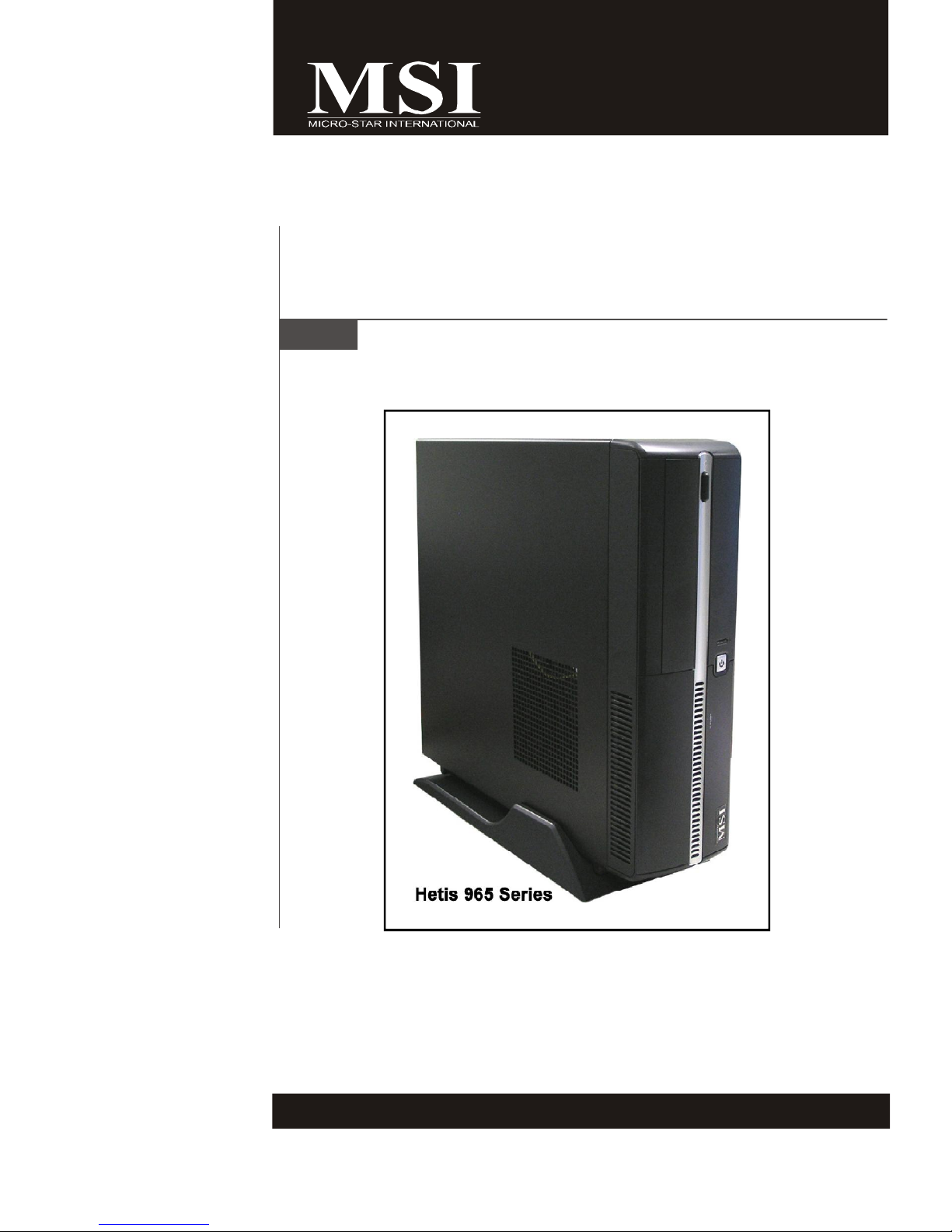
Hetis 965 Series
MS-6441 (V1.X) Barebone
G52-64411X2
Page 2
FCC-B Radio Frequency Interference Statement
This equipment has been tested and
found to comply with the limits for a
class B digital device, pursuant to part
15 of the FCC rules. These limits are
designed to provide reasonable protection against harmful interference in a residential
installation. This equipment generates, uses and can radiate radio frequency energy
and, if not installed and used in accordance with the instruction manual, may cause
harmful interference to radio communications. However, there is no guarantee that
interference will not occur in a particular installation. If this equipment does cause
harmful interference to radio or television reception, which can be determined by
turning the equipment off and on, the user is encouraged to try to correct the
interference by one or more of the measures listed below.
=Reorient or relocate the receiving antenna.
=Increase the separation between the equipment and receiver.
=Connec the equipment into an outlet on a circuit different from that to which the
receiver is connected.
=Consult the dealer or an experienced radio/television technician for help.
Notice 1
The changes or modifications not expressly approved by the party responsible for
compliance could void the user’s authority to operate the equipment.
Notice 2
Shielded interface cables and A.C. power cord, if any, must be used in order to
comply with the emission limits.
VOIR LA NOTICE D’INSTALLATION AVANT DE RACCORDER AU RESEAU.
Micro-Star International
Hetis 965
This device complies with Part 15 of the FCC Rules. Operation is subject to the
following two conditions:
(1) this device may not cause harmful interference, and
(2) this device must accept any interference received, including interfer ence that
may cause undesired operation.
ii
Page 3

Trademarks
All trademarks are the properties of their respective owners.
Intel® and Pentium® are registered trademarks of Intel Corporation.
PS/2 and OS®/2 are registered trademarks of International Business Machines
Corporation.
Windows® 95/98/2000/NT/XP are registered trademarks of Microsoft Corporation.
Netware® is a registered trademark of Novell, Inc.
Award® is a registered trademark of Phoenix Technologies Ltd.
AMI® is a registered trademark of American Megatrends Inc.
U.S. Patent Numbers.
4,631,603; 4,819,098; 4,907,093; 5,315,448; and 6,516,132.
This product incorporates copyright protection technology that is protected by U.S.
patents and other intellectual property rights. Use of this copyright protection technology must be authorized by Macrovision, and is intended for home and other limited
viewing uses only unless otherwise authorized by Macrovision. Reverse engineer-
ing or disassembly is prohibited.
Revision History
Revision Revision History Date
V1.1 First release May 2007
Copyright Notice
The material in this document is the intellectual property of MICRO-STAR
INTERNATIONAL. We take every care in the preparation of this document, but no
guarantee is given as to the correctness of its contents. Our products are under
continual improvement and we reserve the right to make changes without notice.
iii
Page 4

Safety Instructions
1. Always read the safety instructions carefully.
2. Keep this User’ s Manual for future reference.
3. Keep this equipment away from humidity.
4. Lay this equipment on a reliable flat surface before setting it up.
5. The openings on the enclosure are for air convection hence protects the
equipment from overheating. DO NOT COVER THE OPENINGS.
6. Make sure the voltage of the power source and adjust properly 115/230V
before connecting the equipment to the power inlet.
7. Place the power cord such a way that people can not step on it. Do not
place anything over the power cord.
8. Always Unplug the Power Cord before inserting any add-on card or module.
9. All cautions and warnings on the equipment should be noted.
10. Never pour any liquid into the opening that could damage or cause electrical
shock.
11. If any of the following situations arises, get the equipment checked by a
service personnel:
- The power cord or plug is damaged.
- Liquid has penetrated into the equipment.
- The equipment has been exposed to moisture.
- The equipment has not work well or you can not get it work according to
User’s Manual.
- The equipment has dropped and damaged.
- The equipment has obvious sign of breakage.
12. DO NOT LEAVE THIS EQUIPMENT IN AN ENVIRONMENT UNCONDITIONED,
STORAGE TEMPERATURE ABOVE 400 C (1020F), IT MAY DAMAGE THE
EQUIPMENT.
CAUTION: Danger of explosion if battery is incorrectly replaced.
Replace only with the same or equivalent type recommended by the
manufacturer.
iv
Page 5

Warning:
1. For every changes in powercord’s usage, please use an approved power
cord with condition greater or equal to H05VV-F,3G , 0.75mm2.
2. Internal part is hazardous moving parts, please keep fingers and other
body parts away.
3. For pluggable equipment, the socket-outlet shall be installed near the
equipment and shall be easily accessible.
4. Do not disable the protective earth pin from the plug, the equipment must
be connected to an earthed mains socket-outlet.
v
Page 6
WEEE Statement
vi
Page 7
vii
Page 8
viii
Page 9

CONTENTS
Chapter 1. Getting Started................................................................................1-1
Mainboard Specifications................................................................................1-2
System Configuration......................................................................................1-4
Thermal Solution..............................................................................................1-7
Chapter 2. Hardware Setup..............................................................................2-1
Mainboard Layout...........................................................................................2-2
CPU (Central Processing Unit)........................................................................2-3
Memory............................................................................................................2-4
Power Supply..................................................................................................2-5
Front Panel.......................................................................................................2-6
Back Panel.......................................................................................................2-7
Connectors......................................................................................................2-9
Jumper.............................................................................................................2-12
Slot..................................................................................................................2-13
Chapter 3. System Assembly...........................................................................3-1
Overview........................................................................................................3-2
Installation Procedures.....................................................................................3-4
Chapter 4. BIOS Setup.........................................................................................4-1
Entering Setup.................................................................................................4-2
The Menu Bar.................................................................................................4-4
Main.................................................................................................................4-5
Advanced........................................................................................................4-6
Boot.................................................................................................................4-13
Security...........................................................................................................4-16
Chipset............................................................................................................4-17
Exit...................................................................................................................4-20
Appendix A. Realtek ALC888 Audio................................................................A-1
Installing the Realtek HD Audio Driver.............................................................A-2
Software Configuration..................................................................................A-4
Hardware Setup...........................................................................................A-18
ix
Page 10
Chapter 1
Getting Started
Congratulations for purchasing Hetis 965 Series (MS-6441)
Barebone. Hetis 965 Series is your best Slim PC choice.
With the fantastic appearance and small form factor, it
can easily be set anywhere. The feature packed platform
also gives you an exciting PC experience.
Page 11
MS-6441 Barebone
Mainboard Specifications
Processor Support
- Supports Intel® Celeron D, Pentium 4, Pentium D, Core 2 Duo / Core
2 Extreme (Conroe) / Core 2 Quad (Kentsfield) processors in LGA775
Package.
Supported FSB
- 533 / 800 / 1066 MHz
Chipset
- North Bridge: Intel® G965 Chipset
- South Bridge: Intel® ICH8 Chipset
Memory Support
- DDR2 533 / 667 / 800 SDRAM (4GB Max)
- 2 DDR2 DIMMs (240pin / 1.8V)
LAN
- Supports Giga LAN by Intel® 82566DC
IEEE 1394
- Chip integrated by VIA® VT6307
- Transfer rate is up to 400Mbps
Audio
- Chip integrated by Realtek® ALC888
- Flexible 8-channel audio
- Compliant with Azalia 1.0 Spec
IDE
- 1 IDE port by JMicron JMB368
- Supports Ultra DMA 66 / 100 mode
- Supports PIO, Bus Master operation mode
SATA
- 2 SATA ports by Intel® ICH8
- Supports two SATA devices
- Supports storage and data transfers at up to 300 MB/s
1-2
Page 12
Connectors
Back Panel
- 1 PS/2 Mouse Port
- 1 PS/2 Keyboard Port
- 2 Serial Ports
- 1 VGA Port
- 1 LAN Jack (RJ45)
- 1 IEEE 1394 Port
- 4 USB 2.0 Ports
- 6 Audio Jacks
Front Panel
- 2 Audio Jacks (Headphone and Microphone)
- 2 USB 2.0 Ports
- 1 IEEE 1394 Port
- 1 Chassis Intrusion Switch
Getting Started
On-Board Pinheaders
- 1 CD-In Pinheader
- 1 Card Reader Pinheader
- 1 SPDIF-Out Pinheader
(For HDMI Graphics Card Audio Line Use Only)
Slots
- 1 PCI-X Slot (For Riser Card Use Only)
Form Factor
- Proprietary (334MM x 190 MM)
Mounting
- 5 mounting holes
1-3
Page 13
MS-6441 Barebone
System Configuration
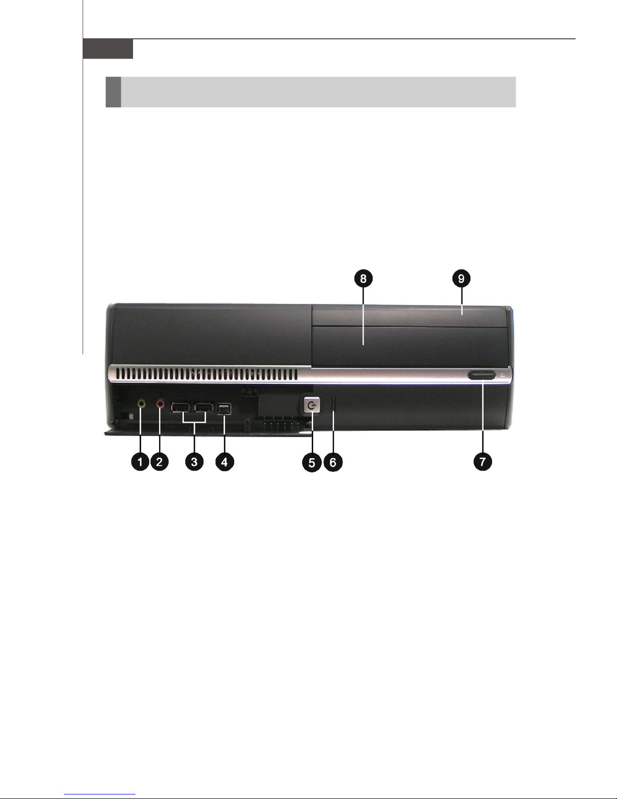
Front View
1. Headphone (Green) 6. HDD LED
2. Microphone (Pink) 7. ODD Eject / Close Button
3. USB 2.0 Ports 8. Optical Disk Drive (Optional)
4. IEEE 1394 Port 9. Card Reader Drive (Optional)
5. Power Button / Power LED
1-4
Page 14

Back View
Getting Started
1. Voltage Selector 8. VGA Port
2. Power Jack 9. Audio Jacks
3. Ventilation Hole 10. Power Switch
4. USB 2.0 Ports 11. Support Bracket Spring
5. PS/2 Mouse (Green) 12. LAN Jack (RJ45)
6. PS/2 Keyboard (Purple) 13. IEEE 1394 Port
7. Serial Ports 14. Expansion Slots
1-5
Page 15
MS-6441 Barebone
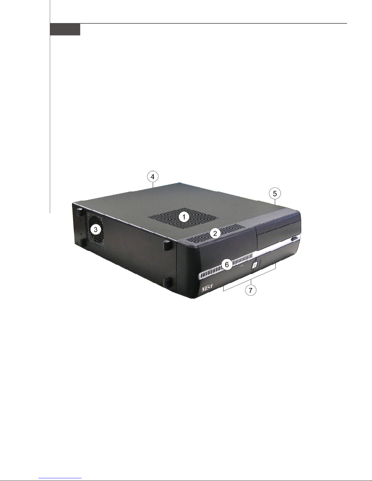
Chassis Design
† Dimension: 330MM (D) x 320MM (W) x 94MM (H)
† Minimized screw structure
† Detachable bay housing
† Multiple ventilation holes
Back
Side
Bottom
1. CPU Fan Ventilation Hole 5. System Ventilation Hole
2. System Ventilation Hole 6. System Ventilation Hole
3. System Fan Ventilation Hole 7. System Ventilation Hole
4. Power Supply Ventilation Hole
1-6
Page 16
Getting Started
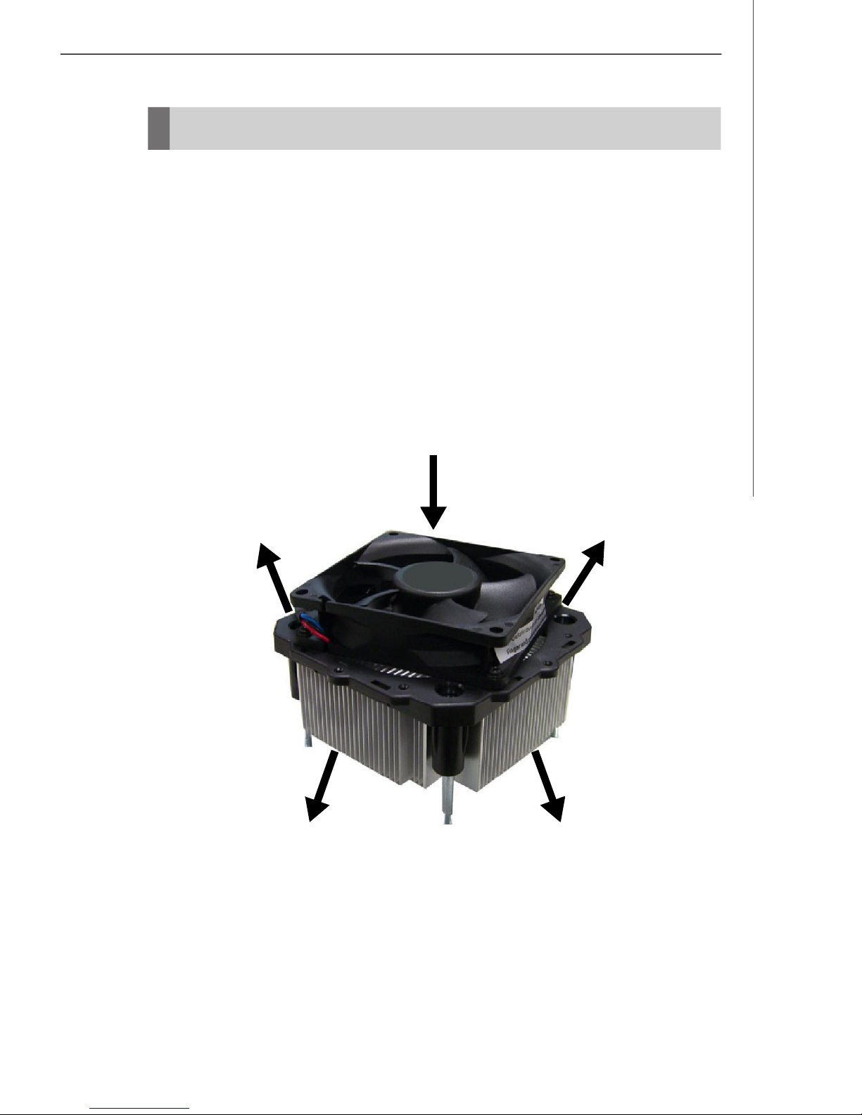
Thermal Solution
To prevent the system from overheating, we have adopted a specially designed CPU
cooler and multiple ventilation holes for better cooling effects. The specially designed
CPU cooler supports Intel® LGA775 - Prescott Pentium® D and Conroe CoreTM E6000
Sequence. The following figures illustrate how the system fan effectively exhausts
hot air through multiple ventilation holes.
CPU Cooler Air Flow Direction
Air In
Air Out Air Out
Air Out
Air Out
1-7
Page 17
MS-6441 Barebone
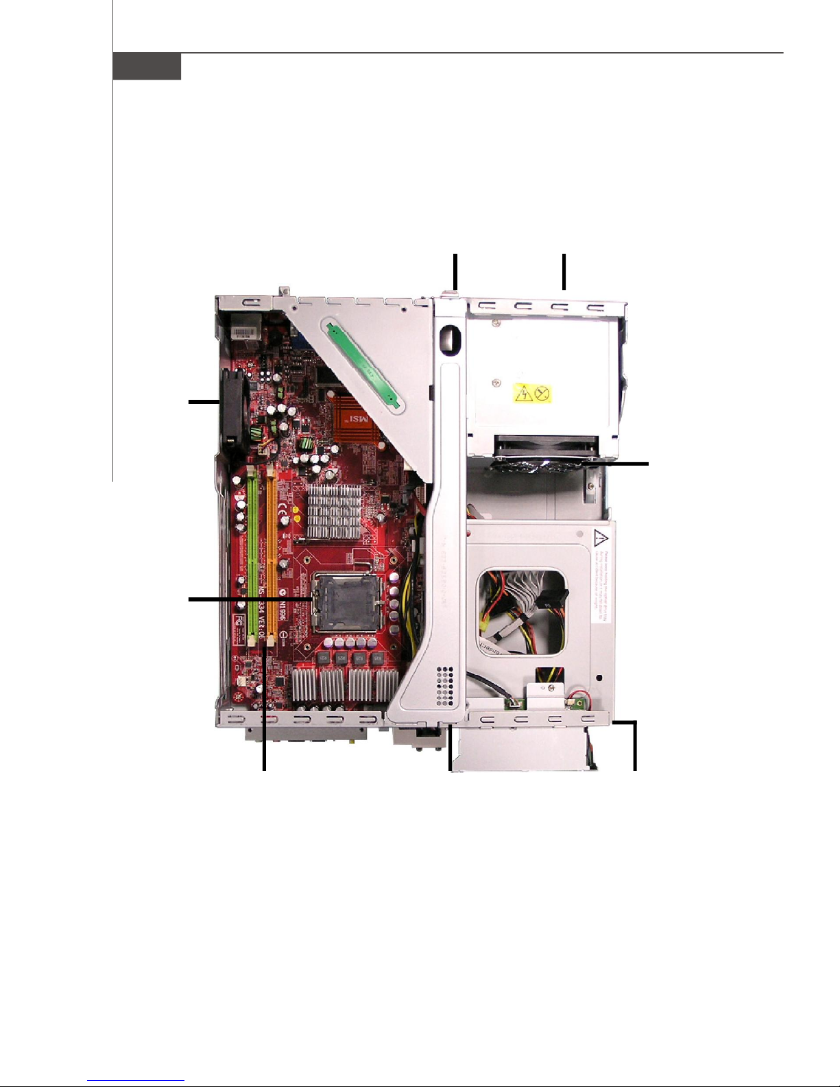
System Design
System
Fan
Back Panel Power Supply
Power
Supply Fan
CPU
Socket
Memory
DIMM Slots
Front Panel
Driver Bays
(from top to bottom)
Card Reader Drive
Optical Disk Drive
Hard Disk Drive
1-8
Page 18
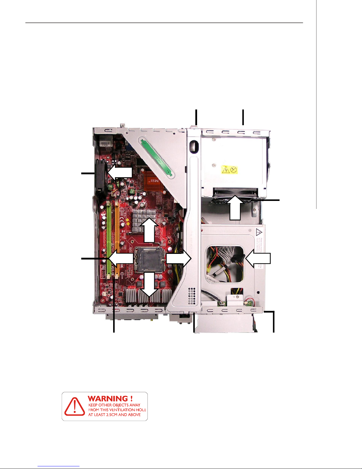
System Air Flow Direction
System
Fan
Getting Started
Back Panel Power Supply
Power
Supply Fan
CPU
Socket
Memory
DIMM Slots
Front Panel
After the installation is completed, please keep other
objects away from the ventilation hole at least 2.5cm
and above. Do not block the ventilation hole.
Driver Bays
(from top to bottom)
Card Reader Drive
Optical Disk Drive
Hard Disk Drive
1-9
Page 19

Chapter 2
Hardware Setup
This chapter provides you with the information about hardware setup procedures. While doing the installation, be
careful in holding the components and follow the installation
procedures. For some components, if you install in the wrong
orientation, the components will not work properly.
Use a grounded wrist strap before handling computer
components. Static electricity may damage the components.
ONLY FOR SERVICE PERSONEL
Always unplug the power cord before
inserting any add-on card or module.
Page 20
MS-6441 Barebone
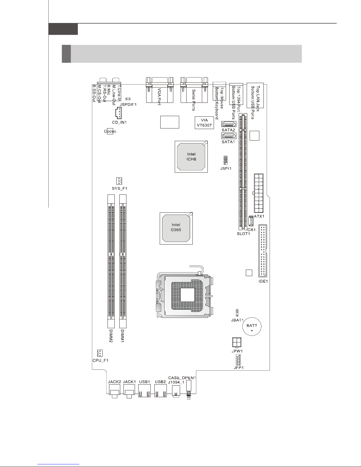
Mainboard Layout
2-2
MS-7334 (V1.X) Mainboard
Page 21

Hardware Setup
CPU (Central Processing Unit)
The mainboard supports Intel® Prescott Pentium® D and Intel® Conroe CoreTM E6000
Sequence. The mainboard uses a CPU socket called LGA775. When you are installing the CPU, make sure to install the cooler to prevent overheating. If you do not have
the CPU cooler, contact your dealer to purchase and install them before turning on the
computer.
Important
Overheating
Overheating will seriously damage the CPU and system, always make
sure the cooling fan can work properly to protect the CPU from
overheating.
Replacing the CPU
While replacing the CPU, always turn off the power supply or unplug the
power supply’s power cord from grounded outlet first to ensure the
safety of CPU.
Overclocking
This motherboard is designed to support overclocking. However, please
make sure your components are able to tolerate such abnormal setting,
while doing overclocking. Any attempt to operate beyond product specifications is not recommended. We do not guarantee the damages or
risks caused by inadequate operation or beyond product specifications.
2-3
Page 22
MS-6441 Barebone
Memory
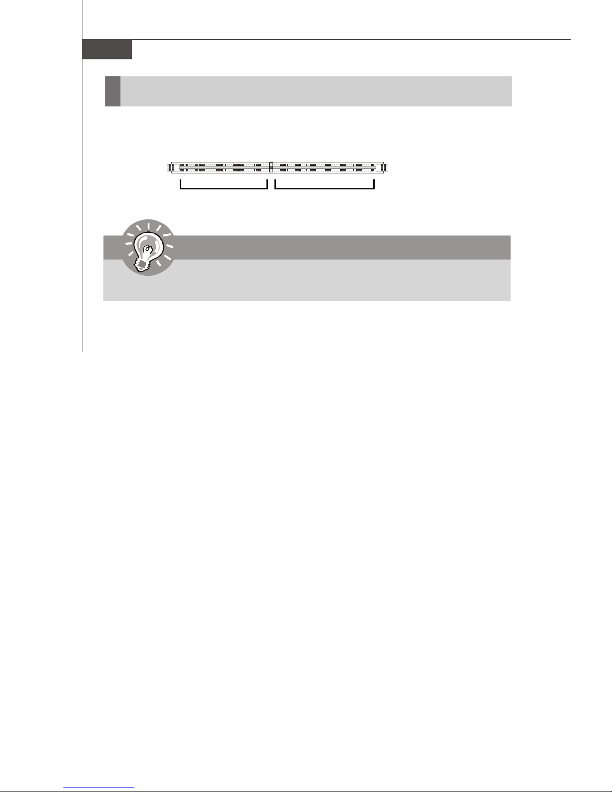
These DIMM slots are used for installing memory modules.
DIMM1~2
240-pin, 1.8V
56 x 2 = 112-pin
64 x 2 = 128-pin
Important
Each DIMM slot supports up to a maximum size of 2GB.
2-4
Page 23
Hardware Setup
Power Supply
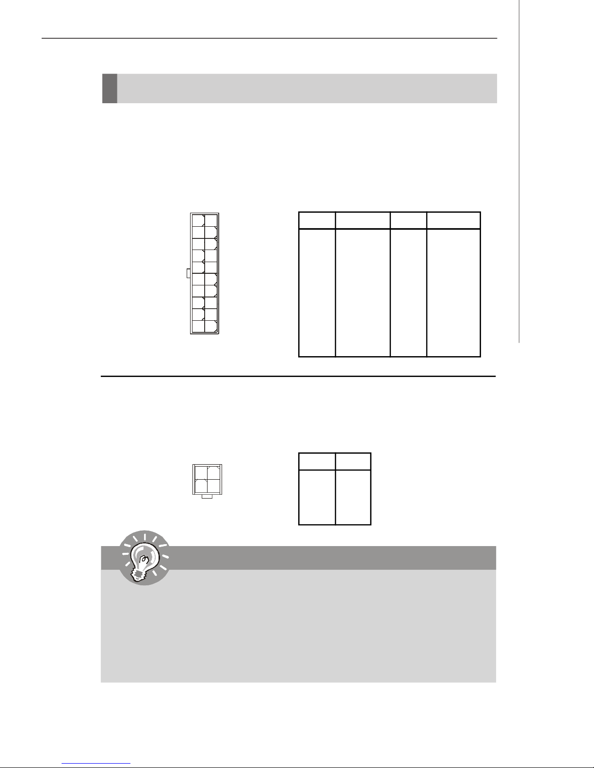
ATX 20-Pin Power Connector: ATX1
This connector allows you to connect to an power supply. To connect to the power
supply, make sure the plug of the power supply is inserted in the proper orientation
and the pins are aligned. Then push down the power supply firmly into the connector.
11
20
ATX1
1
10
PIN SIGNAL
1 3.3V
2 3.3V
3 GND
4 5V
5 GND
6 5V
7 GND
8 PW_OK
9 5V_SB
10 12V
ATX 12V Power Connector: JPW1
This 12V power connector is used to provide power to the CPU.
Pin Definition
Pin Definition
2
4
JPW1
1
3
PIN SIGNAL
1 GND
2 GND
3 12V
4 12V
PIN SIGNAL
11 3.3V
12 -12V
13 GND
14 PS_ON
15 GND
16 GND
17 GND
18 -5V
19 5V
20 5V
Important
1. Make sure that all the connectors are connected to proper ATX power
supplies to ensure stable operation of the mainboard.
2. Power supply of 250 watts (and above) is highly recommended for
system stability.
3. ATX 12V power connection should be greater than 18A.
4. For this model, you must use a power supply that comes with a -5V pin
supply.
2-5
Page 24
MS-6441 Barebone
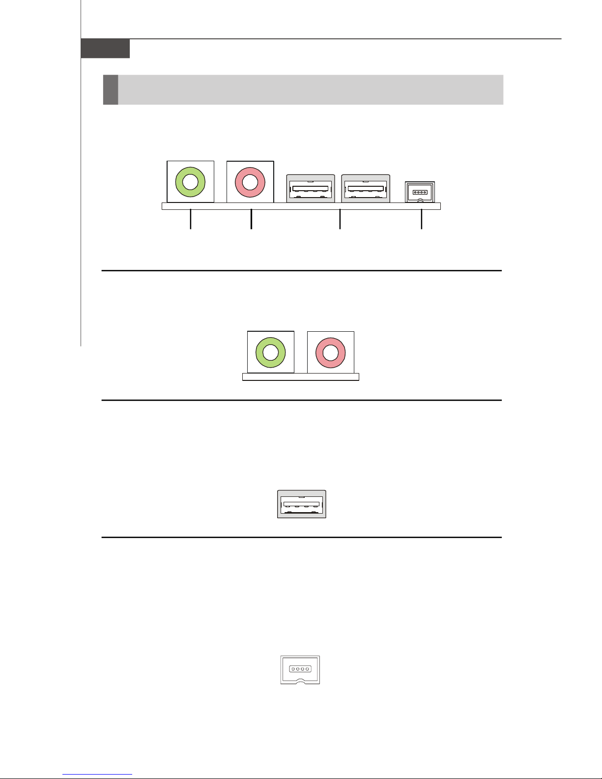
Front Panel
The Front Panel provides the following connectors:
Headphone
(Green)
(Pink)
USB PortsMicrophone
1394 Port
Audio Ports
These audio ports allow you to connect front audio devices.
USB Ports
The mainboard provides a UHCI (Universal Host Controller Interface) Universal Serial
Bus root for attaching USB devices such as keyboard, mouse or other USB-compatible devices. You can plug the USB devices directly into these connectors.
1394 Port
The front panel provides one IEEE 1394 port. This smaller one is designed for you to
connect the IEEE 1394 device with external power. The IEEE 1394 high-speed serial
bus complements USB by providing enhanced PC connectivity for a wide range of
devices, including consumer electronics audio/video (A/V) appliances, storage
peripherals, other PCs, and portable devices.
2-6
Page 25
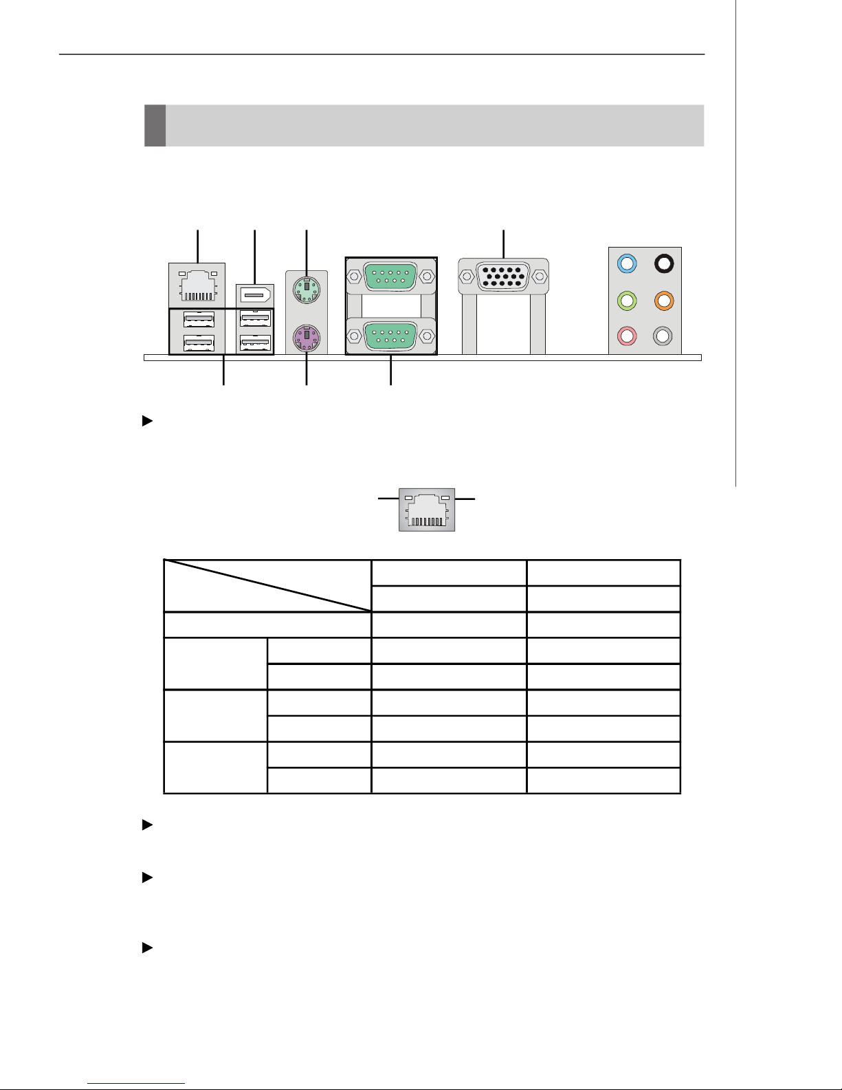
Back Panel
The Rear Panel provides the following connectors:
Hardware Setup
LAN
1394 Port
USB Ports Keyboard
Mouse VGA Port
Serial Ports
Line-In
Line-Out
Mic
RS-Out
CS-Out
SS-Out
LAN
The standard RJ-45 LAN jack is for connection to the Local Area Network (LAN). You
can connect a network cable to it.
Right LEDLeft LED
Left LED
Active LED
Right LED
10 / 100 / 1000M Speed LED
LED Color
10M Cable
Plug-in
100M Cable
Plug-in
1000M Cable
Plug-in
No Transmission
Transition
No Transmission
Transition
No Transmission
Transition
Yellow
OFF
Yellow, Blinking
OFF
Yellow, Blinking
OFF
Yellow, Blinking
Green / Orange
OFF
OFF
Green, Lighting
Green, Lighting
Orange, Lighting
Orange, Lighting
1394 Port
The IEEE1394 port on the back panel provides connection to IEEE1394 devices.
USB Ports
The USB (Universal Serial Bus) port is for attaching USB devices such as keyboard,
mouse, or other USB-compatible devices.
Mouse / Keyboard
The standard PS/2® mouse/keyboard DIN connector is for a PS/2® mouse/keyboard.
2-7
Page 26

MS-6441 Barebone
Serial Ports
The serial port is a 16550A high speed communications port that sends/ receives 16
bytes FIFOs. You can attach a serial mouse or other serial devices directly to the
connector.
VGA Port
The DB15-pin female connector is provided for monitor.
Audio Ports
These audio connectors are used for audio devices. You can differentiate the color
of the audio jacks for different audio sound effects.
Line-In (Blue) - Line In, is used for external CD player, tapeplayer or other
audio devices.
Line-Out (Green) - Line Out, is a connector for speakers or headphones.
Mic (Pink) - Mic, is a connector for microphones.
RS-Out (Black) - Rear-Surround Out in 4/ 5.1/ 7.1 channel mode.
CS-Out (Orange) - Center/ Subwoofer Out in 5.1/ 7.1 channel mode.
SS-Out (Gray) - Side-Surround Out 7.1 channel mode.
2-8
Page 27

Hardware Setup
Connectors
IDE Connector: IDE1
This connector supports IDE hard disk drives, optical disk drives and other IDE devices.
IDE1
Important
If you install two IDE devices on the same cable, you must configure the
drives separately to Master / Slave mode by setting jumpers. Refer to
IDE device’s documentation supplied by the vendors for jumper setting
instructions.
Card Reader Connector: CR1
The mainboard provides a connector to connect the Card Reader on the Front Panel.
CR1
2-9
Page 28

MS-6441 Barebone
Serial ATA Connectors: SATA1 / SATA2
These connectors are high-speed Serial ATA interface port. Each connector can
connect to one Serial ATA device.
SATA1 / SATA2
Fan Power Connectors: CPU_F1 / SYS_F1
The CPU_F1 (processor fan) and SYS_F1 (system fan) support system cooling fan
with +12V. It supports three-pin head connector. When connecting the wire to the
connectors, always take note that the red wire is the positive and should be connected to the +12V, the black wire is Ground and should be connected to GND. The
mainboard has a Super I/O to detect CPU/fab temperature, you must use a specially
designed fan with speed sensor to take advantage of the CPU fan control.
GND
+12V
Sensor
Sensor
+12V
GND
CPU_F1 SYS_F1
Important
Please refer to the recommended CPU fans at processor’s official
website or consult the vendors for proper CPU cooling fan.
2-10
Page 29

Hardware Setup
Front Panel Connector: JFP1
This connector is for electrical connection to the front panel switches and LEDs. The
JFP1 is compliant with Intel® Front Panel I/O Connectivity Design Guide.
Pin Definition
Power
Switch++
Power
LED
-
10 9
2 1
JFP1
+
Reset
-
Switch
-
HDD
LED
PIN
1
2
3
4
5
6
7
8
9
SIGNAL
HD_LED_P
FP PWR/SLP
HD_LED_N
FP PWR/SLP
RST_SW_N
PWR_SW_P
RST_SW_P
PWR_SW_N
RSVD_DNU
Hard disk LED pull-up
MSG LED pull-up
Hard disk active LED
MSG LED pull-up
Reset Switch low reference pull-down to GND
Power Switch high reference pull-up
Reset Switch high reference pull-up
Power Switch low reference pull-down to GND
Reserved. Do not use.
DESCRIPTION
CD-In Connector: CD_IN1
This connector is provided for external audio input.
R
GND
L
CD_IN1
SPDIF-Out Connector: JSPDIF1
(For HDMI Graphics Card Audio Line Use Only)
This connector is used to connect SPDIF (Sony & Philips Digital Interconnect Format)
interface for digital audio transmission to the HDMI graphics card.
SPDIFO GND
JSPDIF1
2-11
Page 30

MS-6441 Barebone
Jumper
Clear CMOS Jumper: JBAT1
There is a CMOS RAM onboard that has a power supply from an external battery to
keep the data of system configuration. With the CMOS RAM, the system can automatically boot OS every time it is turned on. If you want to clear the system configuration,
set the jumper to clear data.
1
3
1
3
1
3
JBAT1 Keep Data Clear Data
Important
You can clear CMOS by shorting 2-3 pin while the system is off. Then
return to 1-2 pin position. Avoid clearing the CMOS while the system is
on; it will damage the mainboard.
2-12
Page 31

Hardware Setup
Slot
PCI-X Slot: SLOT1 (For Riser Card Use Only)
The mainboard provides one PCI-X express slot. The PCI-X slot allows you to insert
Riser Cards and the Riser Cards are included in the barebone. The Riser Cards
allows you to insert PCI/PCI-E expansion card. You can insert any type of PCI cards
and standard PCI-E to meet your needs. When adding or removing expansion cards,
make sure that you unplug the power supply first. Meanwhile, read the documentation for the expansion card to make any necessary hardware or software settings.
Riser Card
2-13
Page 32

System Assembly
Chapter 3
System Assembly
This chapter provides you with the information about system assembly procedures. While doing the installation, be
careful in holding the components and follow the installation procedures.
Use a grounded wrist strap before handling computer
components. Static electricity may damage the components.
ONLY FOR SERVICE PERSONEL
Always unplug the power cord before
inserting any add-on card or module.
3-1
Page 33

MS-6441 Barebone
Overview
The built-in mainboard (MS-7334) is designed for Hetis 965 Series (MS-6441) barebone
only. Except the mainboard, the built-in components of the barebone include power
supply. In this chapter, we will show you how to install CPU, CPU Cooler, Memory
Modules, Card Reader, Hard Disk Drive (HDD) and Optical Disk Drive (ODD).
Installation Tools
Cross type screwdriver, can be used to do most of the
installation. Choose one with a magnetic head would be better.
Pliers, can be used as an auxiliary tool to connect some connectors or cables.
Forceps, can be used to pick up tiny screws or set up the
jumpers.
Rubber gloves, can prevent yourself from being incised and
suffering the static charge.
Installation Screws
Two types of screws are used in assembling the barebone: Round-headed screw
and thumb screw.
Round-headed screw: This type of screw is used to attach
the HDD and Card Reader to the tray.
3-2
Page 34

System Assembly
Checking the Items
Before assembling your system, please check the items listed below for basic system operation. The footstand and the CPU cooler are included in the package, other
items are optional.
Footstand
CPU (Optional) ODD (Optional)
HDD (Optional)
CPU Cooler
Memory Module (Optional)
Card Reader (Optional)
*These pictures are for your refer-
ence only. Your packing contents may
vary depending on the model you
purchased.
3-3
Page 35

MS-6441 Barebone
Installation Procedures
1. Removing Chassis Cover
Unlock the two screws on the back
panel with hands.
Remove the chassis cover.
Press the level on the support bracket
spring to release it.
Unlock the screw on the front panel to
release the drive cage.
3-4
Page 36

2. Installing Hard Disk Drive (HDD)
Lift the drive cage to slide aside.
Pull the HDD tray forwards to remove it
from the chassis.
System Assembly
Put the HDD in the HDD tray and use
four screws to fix it on both sides.
Connect the cable and the power cord
to the HDD, then put the HDD tray back
to secure it on the drive cage.
3-5
Page 37

MS-6441 Barebone
3. Installing Optical Disk Drive (ODD)
Pull the lock brackets outwards on the
both sides to release.
Insert the ODD and push the lock brackets back to fix it.
Connect the cable and the power cord
to the ODD, then restore the drive cage.
Lock the screw on the front panel to
fix the drive cage.
3-6
Page 38

4. Installing Card Reader (Optional)
Use the screwdriver to unlock the card
reader cage.
Insert the card reader into the cage
with 15 degree angle.
System Assembly
Insert the LED into the cage and lock
the card reader with two screws.
Restore the card reader back and connect the cable to the CR1 connector on
the mainboard.
3-7
Page 39

MS-6441 Barebone
5. Installing Memory Modules
Locate the DIMM slots.
Insert the DIMM vertically into the slot.
Note: The DIMM has only one notch
on the center of module. It will only fit
in the right direction.
3-8
Page 40
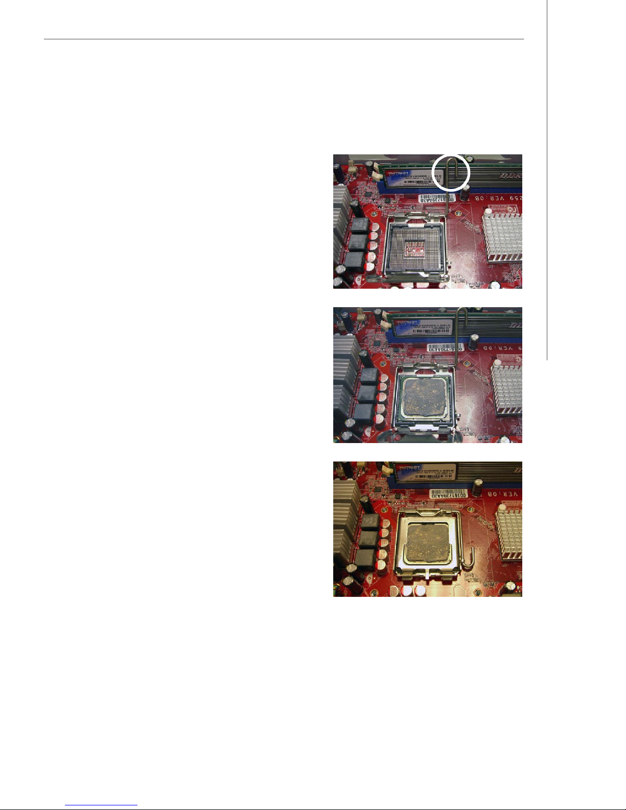
6. Installing CPU
Locate the CPU socket. Pull the lever
away from the socket and raise it up,
then lift up the cover.
Put the CPU onto the socket.
Note: Make sure the pins are completely embedded into the socket. The
CPU can only fit in the correct
direction.
System Assembly
Close the cover and the lever to complete the installaton.
3-9
Page 41

MS-6441 Barebone
7. Installing CPU Cooler
Place the CPU cooler onto the CPU
socket and secure the four screws.
Important
Do not fix any screw until all the four screws are in the position, and
lock the four screws with balance, or it may shift the CPU position to
cause the system unbootable.
Connect the CPU cooler’s power cord
to the connector on the mainboard.
3-10
Page 42

8. Restoring Chassis Cover
Restore the support bracket.
Restore the chassis cover.
System Assembly
Lock the chassis cover with the
screws.
Horizontal typeTower type
3-11
Page 43

MS-6441 Barebone
9. Installing Footstand
Lift up the PC and put the rubber feet
into the pits on the footstand.
Make sure the rubber feet to get stuck
on the footstand.
Put the PC on the footstand or lay on
the rubber foots.
3-12
Page 44

Chapter 4
BIOS Setup
This chapter provides information on the BIOS Setup program and allows you to configure the system for optimum
use.
You may need to run the Setup program when:
An error message appears on the screen during the
system booting up, and requests you to run SETUP.
You want to change the default settings for customized
features.
BIOS Setup
4-1
Page 45

MS-6441 Barebone
Entering Setup
Power on the computer and the system will start POST (Power On Self Test) process.
When the message below appears on the screen, press <DEL> key to enter Setup.
Press DEL to enter SETUP
If the message disappears before you respond and you still wish to enter Setup,
restart the system by turning it OFF and On or pressing the RESET button. You may
also restart the system by simultaneously pressing <Ctrl>, <Alt>, and <Delete> keys.
Important
1. The items under each BIOS category described in this chapter are
under continuous update for better system performance. Therefore, the
description may be slightly different from the latest BIOS and should be
held for reference only.
2. Upon boot-up, the 1st line appearing after the memory count is the BIOS
version. It is usually in the format:
A7334IMS V1.0 070124 where:
1st digit refers to BIOS maker as A = AMI, W = AWARD, and P =
PHOENIX.
2nd - 5th digit refers to the model number.
6th digit refers to the chipset as I = Intel, N = nVidia, and V = VIA.
7th - 8th digit refers to the customer as MS = all standard customers.
V1.0 refers to the BIOS version.
070124 refers to the date this BIOS was released.
4-2
Page 46

BIOS Setup
Control Keys
<↑> Move to the previous item
<↓> Move to the next item
<←> Move to the item in the left hand
<→> Move to the item in the right hand
<Enter> Select the item
<Esc> Jumps to the Exit menu or returns to the main menu from a submenu
<+/PU> Increase the numeric value or make changes
<-/PD> Decrease the numeric value or make changes
<F10> Save all the CMOS changes and exit
Getting Help
After entering the Setup menu, the first menu you will see is the Main Menu.
Main Menu
The main menu lists the setup functions you can make changes to. You can use the
arrow keys (↑↓) to select the item. The on-line description of the highlighted setup
function is displayed at the bottom of the screen.
Sub-Menu
If you find a right pointer symbol (as shown in
the right view) appears to the left of certain
fields that means a sub-menu can be launched
from this field. A sub-menu contains additional
options for a field parameter. You can use arrow keys (↑↓) to highlight the field and
press <Enter> to call up the sub-menu. Then you can use the control keys to enter
values and move from field to field within a sub-menu. If you want to return to the
main menu, just press the <Esc>.
General Help <F1>
The BIOS setup program provides a General Help screen. You can call up this screen
from any menu by simply pressing <F1>. The Help screen lists the appropriate keys
to use and the possible selections for the highlighted item. Press <Esc> to exit the
Help screen.
4-3
Page 47

MS-6441 Barebone
The Menu Bar
Main
Use this menu for basic system configurations, such as time, date etc.
Advanced
Use this menu to set up the items of special enhanced features available on your
system.
Boot
Use this menu to specify the priority of boot devices.
Security
Use this menu to set Supervisor and User Passwords.
Chipset
Use this menu to change the values in the chipset registers and optimize your system’s
performance.
Exit
This menu allows you to load the BIOS default values or factory default settings into
the BIOS and exit the BIOS setup utility with or without changes.
4-4
Page 48

Main
BIOS Setup
- System Overview -
AMI BIOS
This item shows the information of AMI BIOS. (Read-only)
Processor
This item shows the information of Processor. (Read-only)
System Memory
This item shows the information of System Memory. (Read-only)
System Time
This allows you to set the system time that you want (usually the current time). The
time format is <hour> <minute> <second>.
System Date
This allows you to set the system to the date that you want (usually the current date).
The format is <day> <month> <date> <year>.
[Day] Day of the week, from Sun to Sat, determined by BIOS.
[Month] The month from Jan. through Dec.
[Date] The date from 1 to 31 can be keyed by numeric function keys.
[Year] The year can be adjusted by users.
4-5
Page 49

MS-6441 Barebone
Advanced
- Advanced Settings -
CPU Configuration
Press <Enter> and the following sub-menu appears:
4-6
Page 50

BIOS Setup
- Configure advanced CPU settings -
Manufacturer / Brand String
These items show the CPU related information of your system. (Read-only)
Frequency / FSB Speed
These items show the current CPU Front Side Bus (FSB) clock frequency and
speed. (Read-only)
Cache L1 / L2
Cache memory is additional memory that is much faster than conventional
DRAM (system memory). When the CPU requests data, the system transfers
the requested data from the main DRAM into cache memory, for even faster
access by the CPU. This item shows the internal cache (also known as L1 or
level 1 cache) and external cache (also known as L2 or level 2 cache).
Ratio Status / Ratio Actual Value
These items show the CPU ratio status and CPU ratio actual value. (Read-only)
Core Multi-Processing
This item allows user to enable or disable the Multi-Core function.
Intel(R) C-State tech.
C1 Config.
This item allows user to set the C1 state [Disabled], [Standard] or [Enhanced].
4-7
Page 51

MS-6441 Barebone
IDE Configuration
Press <Enter> and the following sub-menu appears:
- IDE Configuration -
Mirrored IDER Configuration
This item allows user to enable or disable the IDER function.
SATA#1 Configuration
This item allows you to configurare IDE device mode.
[Compatible] If Compatible selected, Legacy IDE Channels will be
presented for configuration.
[Enhanced] If Enhanced selected, “Configure SATA as” will be pre
sented for setup.
Configure SATA#1 as
This item allows you to configure SATA mode.
[IDE] As serial ATA only.
[RAID]As SATA RAID mode Supporting RAID0,1,5,10.
[AHCI]If AHCI is chosen, it allows you to enable SATA Stagger Spinup
Support (not RAID mode) and take all hard disks on board as
master.
Primary / Secondary / Third / Fourth IDE Master / Slave
The global timer is the hardware timer that counts down to the power saving
modes. If the monitoring of the listed hardware peripheral or component is
enabled, they will awaken the system or reload the original count of global
timer when they are accessed.
4-8
Page 52
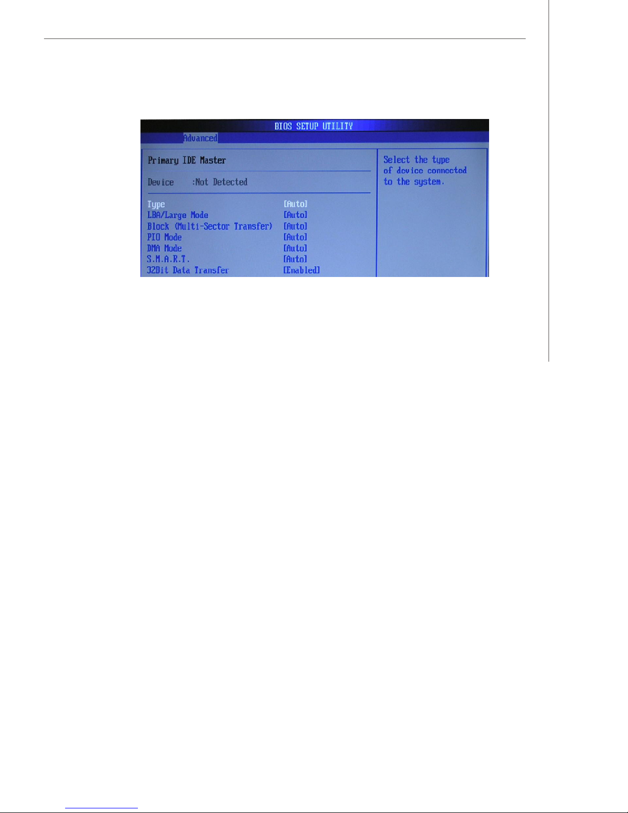
BIOS Setup
- Primary IDE Master -
Type
This item allows you to select the hard disk type. Available setting
options are:[Not Installed], [Auto], [CD/DVD] or [ARMD].
LBA/Large Mode
This item allows you to enable or disable the LBA (Logical Block Address,
the logical block size in hard disk) mode.
Block (Multi-Sector Transfer)
If your IDE hard drive supports block mode (most new drives do),select
[Enabled] for automatic detection of the optimal number of block read/
writes per sector the drive can support.
PIO Mode
This field lets you set a PIO (Programmed Input/Output) mode for the IDE
devices that the onboard IDE interface supports. Modes 0 through 4
provide successively increased performance. In [Auto] mode, the system automatically determines the best mode for each device.
DMA Mode
This item allows you to enable or disable the DMA (Direct Memory
Access) mode.
S.M.A.R.T
This allows you to activate the S.M.A.R.T. (Self-Monitoring Analysis &
Report-ing Technology) capability for the hard disks. S.M.A.R.T is a
utility that monitorsyour disk status to predict hard disk failure. This
gives you an opportunity tomove data from a hard disk that is going to
fail to a safe place before the harddisk becomes offline.
4-9
Page 53

MS-6441 Barebone
32Bit Data Transfer
The IDE interface in the integrated peripherals controller supports 32bit data transfers.Select [Enabled] only if your IDE hard drives can also
support 32-bit transfer mode.
SuperIO Configuration
Press <Enter> and the following sub-menu appears:
- Configure Win627DHG Super IO Chipset -
Serial Port 1 / 2 Address
These items specify the base I/O port addresses of the onboard Serial Port 1
(COM 1). Select [Auto] allows AMI BIOS to automatically determine the correct
base I/O port address.
Chassis Intrusion
The field enables or disables the feature of recording the chassis intrusion
status and issuing a warning message if the chassis is once opened. To clear
the warning message, set the field to [Reset]. The setting of the field will
automatically return to [Enabled] later.
4-10
Page 54

Hardware Health Configuration
Press <Enter> and the following sub-menu appears:
BIOS Setup
- Hardware Health Configuration -
System / CPU Temperature, SYSFAN / CPUFAN Speed, Vcore, VCC(V),
+12V, +5V, 3.3V, VBAT
These items display the current status of all of the monitored hardware devices/components such as CPU voltages, temperatures and all fans’ speeds.
ACPI Configuration
Press <Enter> and the following sub-menu appears:
4-11
Page 55

MS-6441 Barebone
- ACPI Settings -
General ACPI Configuration
Press <Enter> and the following sub-menu appears:
- General ACPI Configuration -
Suspend Mode
Select the type of Suspend mode:
[POS] Power-on suspend (the CPU and core system remain
powered on in a very low-power mode)
[Auto]After the period of inactivity selected in the Auto Sus
pend Timeout field, the system automatically enters STD
mode. If STD mode is unavailable, the system enters
STR mode.
[STD] Save to disk
[STR] Suspend to RAM
Chipset ACPI Configuration
Press <Enter> and the following sub-menu appears:
- South Bridge ACPI Configuration -
USB Device Wakeup From S3/S4
This setting allows you to enter “Any Key” (max. 8 numbers) to wake
up thesystem from S3 state.
High Performance Event Timer
High Performance Event Timer (HPET) is needed to allow OS to discover event timersand establiish basic timer services for driver load.
4-12
Page 56

Boot
BIOS Setup
- Boot Settings -
Boot Settings Configuration
Press <Enter> and the following sub-menu appears:
4-13
Page 57

MS-6441 Barebone
- Boot Settings Configuration -
Quick Boot
Setting the item to [Enabled] allows the system to boot within 5 seconds since
it will skip some check items.
Full Screen Logo Display
This item enables you to show the company logo on the bootup screen. Settings are:
[Enabled] Shows a still image (logo) on the full screen at boot.
[Disabled] Shows the POST messages at boot.
Wait For ’F1’ If Error
This BIOS feature controls the system's response when an error is detected
during the boot sequence. When enabled, the BIOS will halt the boot sequence
when an error is detected. You will need to press the F1 button at this point. It
brings you to the BIOS setup menu where you can adjust the settings to fix the
problem. When disabled, the BIOS will not halt the boot sequence, even when
an error is detected. The system will continue to boot into the operating system.
Boot Device Priority
Press <Enter> and the following sub-menu appears:
- Boot Settings Configuration -
1st / 2nd Boot Device
These items allow you to set the sequence of boot devices where BIOS
attempts to load the operating system.
4-14
Page 58

Hard Disk Drives
Press <Enter> and the following sub-menu appears:
BIOS Setup
- Hard Disk Drives 1st Drive
This item allows you to set the type of hard disk drives installed.
4-15
Page 59

MS-6441 Barebone
Security
- Security Settings -
Change Supervisor Password
Use this item to change the supervisor password that controls access to the BIOS
Setup utility.
Change User Password
Use this item to change the user password that controls access to the system at
boot.
4-16
Page 60

Chipset
BIOS Setup
- Advanced Chipset Settings -
North Bridge Configuration
Press <Enter> and the following sub-menu appears:
4-17
Page 61

MS-6441 Barebone
- North Bridge Chipset Configuration -
Video Function Configuration
Press <Enter> and the following sub-menu appears:
- Video Function Configuration -
DVMT Mode Select
This item allows you to set the mode for the graphics core.
[Fixed] mode, a fixed-size fragment of the system memory is
allocated to the graphics core. It can only be used by
the graphics core.
[DVMT] mode, the driver of the graphics core uses the system
memory like any other OS component or application
does.
DVMT/FIXED Memory
Specify the size of DVMT/FIXED memory to allocate for video memory.
4-18
Page 62

South Bridge Configuration
Press <Enter> and the following sub-menu appears:
BIOS Setup
- South Bridge Chipset Configuration -
GbE Controller
This item allows user to enable or disable the GbE (Gigabit Ethernet) controller.
GbE LAN Boot
This item allows user to enable or disable the onboard PXE ROM for second
boot.
GbE Wake Up From S5
This item allows user to enable or disable the GbE Wake Up From S5 function.
Restore on AC Power Loss
This setting specifies whether your system will reboot after a power failure or
interrupt occurs. Available settings are:
[Off] Leaves the computer in the power off state.
[On] Leaves the computer in the power on state.
[Last State] Restores the system to the previous status before
power failure or interrupt occurred.
USB 2.0 Controller Mode
Set to [Enabled] if you need to use any USB 2.0 device in the operating system
that does not support or have any USB 2.0 driver installed, such as DOS and
SCO Unix.
Onboard 1394 Device
This setting controls the onboard 1394 device.
4-19
Page 63

MS-6441 Barebone
Exit
- Exit Options -
Save Changes and Exit
Save changes to CMOS and exit setup.
Discard Changes and Exit
Abandon all changes and exit setup.
Discard Changes
Abandon all changes.
Load Optimal Defaults
Use this menu to load the default values set by the mainboard manufacturer specifically for optimal performance of the mainboard.
Load Failsafe Defaults
Use this menu to load the default values set by the BIOS vendor for stable
systemperformance.
4-20
Page 64

Realtek ALC888 Audio
Appendix A
Realtek ALC888 Audio
The Realtek ALC888 provides 10-channel DAC that simultaneously supports 7.1 sound playback and 2 channels of independent stereo sound output (multiple
streaming) through the Front-Out-Left and Front-OutRight channels.
A-1
Page 65

MS-6441 Barebone
Installing the Realtek HD Audio Driver
You need to install the driver for Realtek ALC888 codec to function properly before
you can get access to 2-, 4-, 6-, 8- channel or 7.1+2 channel audio operations.
Follow the procedures described below to install the drivers for different operating
systems.
Installation for Windows 2000/XP
For Windows® 2000, you must install Windows® 2000 Service Pack4 or later before
installing the driver. For Windows® XP, you must install Windows® XP Service Pack1
or later before installing the driver.
The following illustrations are based on Windows® XP environment and could look
slightly different if you install the drivers in different operating systems.
1. Insert the application CD into the CD-ROM drive. The setup screen will automatically appear.
2. Click Realtek HD Audio Driver.
Important
The HD Audio Configuration software utility is under continuous
update to enhance audio applications. Hence, the program screens
shown here in this section may be slightly different from the latest
software utility and shall be held for reference only.
A-2
Click here
Page 66

Realtek ALC888 Audio
3. Click Next to install the Realtek High Definition Audio Driver.
4. Click Finish to restart the system.
Click here
Select this
option
Click here
A-3
Page 67

MS-6441 Barebone
Software Configuration
After installing the audio driver, you are able to use the 2-, 4-, 6- or 8- channel audio
feature now. Click the audio icon from the system tray at the lower-right corner of
the screen to activate the HD Audio Configuration. It is also available to enable the
audio driver by clicking the Realtek HD Audio Manager from the Control Panel.
Double click
A-4
Page 68

Realtek ALC888 Audio
Sound Effect
Here you can select a sound effect you like from the Environment list.
Environment Simulation
You will be able to enjoy different sound experience by pulling down the arrow,
totally 23 kinds of sound effect will be shown for selection. Realtek HD Audio Sound
Manager also provides five popular settings “Stone Corridor”, “Bathroom”, “Sewer
pipe”, “Arena” and “Audio Corridor” for quick enjoyment.
You may choose the provided sound effects, and the equalizer will adjust automatically.
If you like, you may also load an equalizer setting or make an new equalizer setting to
save as an new one by using the “Load EQ Setting” and “Save Preset” button,
click “Reset EQ Setting” button to use the default value, or click “Delete EQ Set-
ting” button to remove a preset EQ setting.
There are also other pre-set equalizer models for you to choose by clicking “Others”
under the Equalizer part.
A-5
Page 69

MS-6441 Barebone
Equalizer Selection
Equalizer frees users from default settings; users may create their owned preferred
settings by utilizing this tool.
10 bands of equalizer, ranging from 100Hz to 16KHz.
Save
The settings are saved
permanently for future
use.
Enable / Disable
To disable, you can temporarily stop the sound
effect without losing the
settings.
Delete
To delete the pre-saved settings which are created from previous
steps.
Reset
10 bands of equalizer
would go back to the
default setting.
Load
Whenever you would
like to use preload
settings, simply click
this, the whole list will
be shown for your
selection.
A-6
Page 70

Realtek ALC888 Audio
Frequently Used Equalizer Setting
Realtek recognizes the needs that you might have. By leveraging our long experience
at audio field, Realtek HD Audio Sound Manager provides you certain optimized equalizer settings that are frequently used for your quick enjoyment.
[How to Use It]
Other than the buttons “Pop” “Live” “Club” & “Rock” shown on the page, to pull down
the arrow in “Others”, you will find more optimized settings available to you.
Karaoke Mode
Karaoke mode brings Karaoke fun back home. Simply using the music you usually
play, Karaoke mode can help you eliminate the vocal of the song or adjust the key to
accommodate your range.
1.Vocal Cancellation: Single click on “Voice Cancellation” , the vocal of the song
would be eliminated, while the background music is still in place, and you can be
that singer!
2.Key Adjustment: Using “Up / Down Arrow” to find a key which better fits your
vocal range.
Remove the
human voice
Raise the key
Lower the key
A-7
Page 71

MS-6441 Barebone
Mixer
In the Mixer part, you may adjust the volumes of the rear and front panels individually.
1. Adjust Volume
You can adjust the volume of the speakers that you pluged in front or rear panel by
select the Realtek HD Audio rear output or Realtek HD Audio front output
items.
Important
Before set up, please make sure the playback devices are well plugged
in the jacks on the rear or front panel. The Realtek HD Audio front
output item will appear after you pluging the speakers into the jacks on
the front panel.
2. Multi-Stream Function
ALC888 supports an outstanding feature called Multi-Stream, which means you may
play different audio sources simultaneously and let them output respectively from the
indicated real panel or front panel. This feature is very helpful when 2 people are
using the same computer together for different purposes.
Click the button and the Mixer ToolBox menu will appear. Then check the Enable
playback multi-streaming and click OK to save the setup.
A-8
Page 72

Realtek ALC888 Audio
Important
You have to plug audio device into the jacks on the rear and front panel first
before enable the multi-stream function.
When you are playing the first audio source (for example: use Windows Media
Player to play DVD/VCD), the output will be played from the rear panel, which is the
default setting.
Then you must to select the Realtek HD Audio front output from the scroll list
first, and use a different program to play the second audio source (for example: use
Winamp to play MP3 files). You will find that the second audio source (MP3 music) will
come out from the Line-Out audio jack of Front Panel.
A-9
Page 73

MS-6441 Barebone
3. Playback control
Tool Mute
Playback device
This function is to let you freely decide which ports
to output the sound. And this is essential when multistreaming playback enabled.
- Realtek HD Audio Rear Output
- Realtek HD Audio Front Output
Mute
You may choose to mute single or multiple volume controls or to completely mute
sound output.
Tool
- Show the following volume controls
This is to let you freely decide which volume control items to be displayed.
- Advanced controls
- Enable playback multi-streaming
With this function, you will be able to have an audio chat with your friends via
headphone (stream 1 from front panel) while still have music (stream 2 from back
panel) in play. At any given period, you can have maximum 2 streams operating
simultaneously.
A-10
Page 74

4. Recording control
Realtek ALC888 Audio
Tool Mute
Recording device
-Back Line in/Mic, Front Lin in
-Realtek HD Audio Input
Mute
You may choose to mute single or multiple volume controls or to completely mute
sound input.
Tool
- Show the following volume controls
This is to let you freely decide which volume control items to be displayed.
- Enable recording multi-streaming
Important
ALC888 allows you to record the CD, Line, Mic and Stereo Mix channels
simultaneously, frees you from mixing efforts. At any given period, you
may choose 1 of the following 4 channels to record.
A-11
Page 75
MS-6441 Barebone
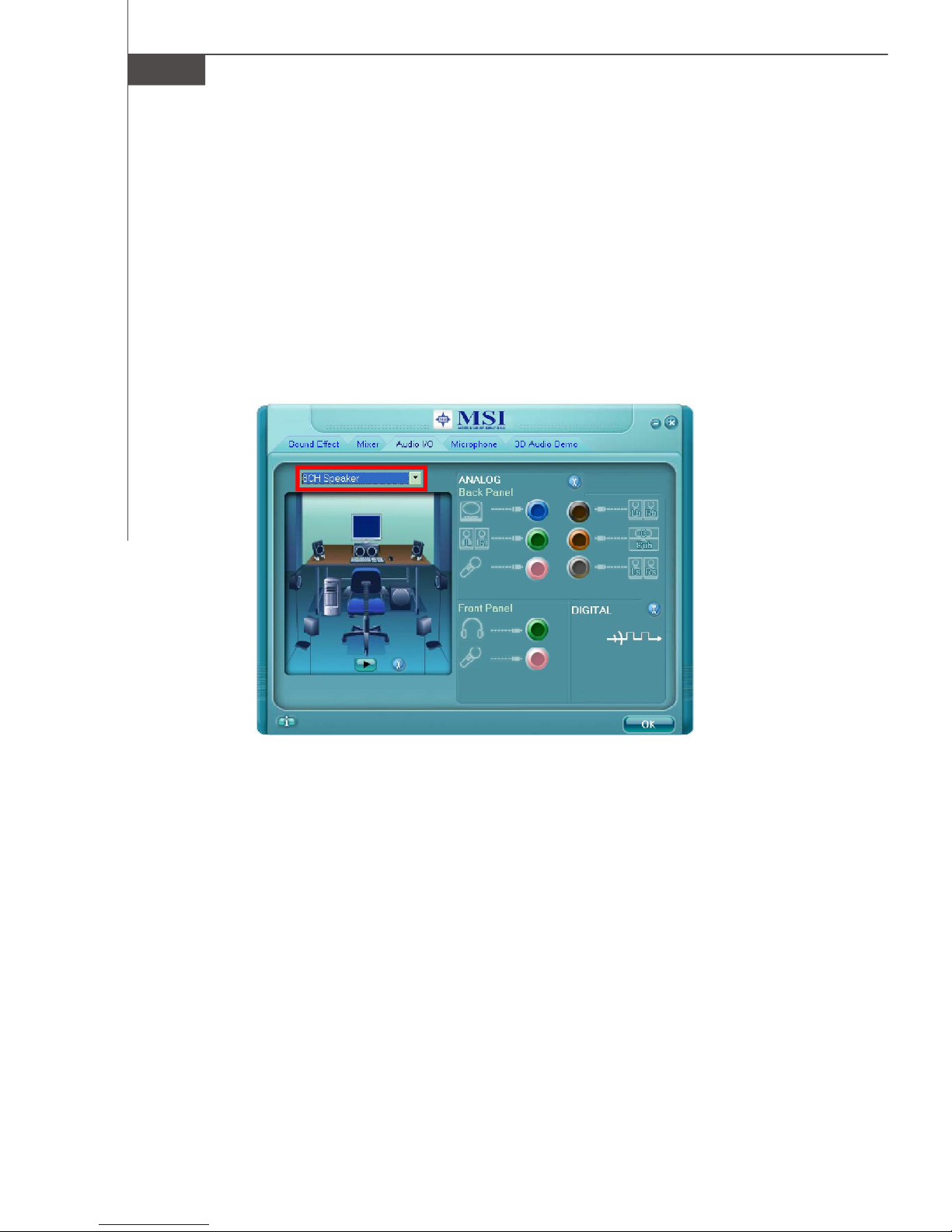
Audio I/O
In this tab, you can easily configure your multi-channel audio function and speakers.
You can choose a desired multi-channel operation here.
a. Headphone for the common headphone
b. 2CH Speaker for Stereo-Speaker Output
c. 4CH Speaker for 4-Speaker Output
d. 6CH Speaker for 5.1-Speaker Output
e. 8CH Speaker for 7.1-Speaker Output
Speaker Configuration:
1. Plug the speakers in the corresponding jack.
2. Dialogue “connected device” will pop up for your selection. Please select the
device you have plugged in.
- If the device is being plugged into the correct jack, you will be able to find the
icon beside the jack changed to the one that is same as your device.
- If not correct, Realtek HD Audio Manager will guide you to plug the device into
the correct jack.
A-12
Page 76
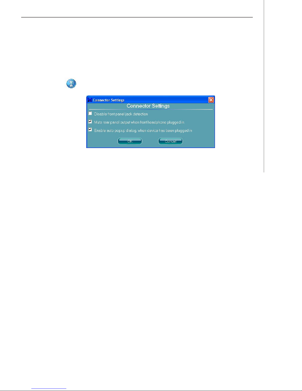
Realtek ALC888 Audio
Connector Settings
Click to access connector settings.
Disable front panel jack detection (option)
Find no function on front panel jacks? Please check if front jacks on your system are
so-called AC’97 jacks. If so, please check this item to disable front panel jack detection.
Mute rear panel output when front headphone plugged in.
Enable auto popup dialogue, when device has been plugged in
Once this item checked, the dialog “Connected device” would automatically pop up
when device plugged in.
A-13
Page 77

MS-6441 Barebone
Test Speakers
You can select the speaker by clicking it to test its functionality. The one you select
will light up and make testing sound. If any speaker fails to make sound, then check
whether the cable is inserted firmly to the connector or replace the bad speakers
with good ones. Or you may click the auto test button to test the sounds of
each speaker automatically.
Center
Front Left
Front Right
Side Left Side Right
Subwoofer
Rear Left
Rear Right
A-14
Page 78

Realtek ALC888 Audio
Microphone
In this tab you may set the function of the microphone. Select the Noise Suppression to remove the possible noise during recording, or select Acoustic Echo
Cancelltion to cancel the acoustic echo druing recording.
Acoustic Echo Cancelltion prevents playback sound from being recorded by mi-
crophone together with your sound. For example, you might have chance to use
VOIP function through Internet with your friends. The voice of your friend will come
out from speakers (playback). However, the voice of your friend might also be
recorded into your microphone then go back to your friend through Internet. In that
case, your friend will hear his/her own voice again. With AEC(Acoustic Echo
Cancellation) enabled at your side, your friend can enjoy the benefit with less echo.
A-15
Page 79
MS-6441 Barebone
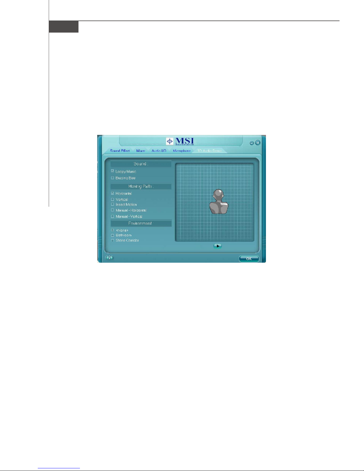
3D Audio Demo
In this tab you may adjust your 3D positional audio before playing 3D audio applications like gaming. You may also select different environment to choose the most
suitable environment you like.
A-16
Page 80

Realtek ALC888 Audio
Information
In this tab it provides some information about this HD Audio Configuration utility,
including Audio Driver Version, DirectX Version, Audio Controller & Audio Codec. You
may also select the language of this utility by choosing from the Language list.
Also there is a selection Show icon in system tray . Switch it on and an icon
will show in the system tray. Right-click on the icon and the Audio Accessories
dialogue box will appear which provides several multimedia features for you to take
advantage of.
A-17
Page 81

MS-6441 Barebone
Hardware Setup
Connecting the Speakers
When you have set the Multi-Channel Audio Function mode properly in the software
utility, connect your speakers to the correct phone jacks in accordance with the
setting in software utility.
n 2-Channel Mode for Stereo-Speaker Output
Refer to the following diagram and caption for the function of each phone jack on the
back panel when 2-Channel Mode is selected.
Back Panel
1
2
4
1 Line-In
2 Line-Out (Front channels)
3 Mic
4 No function
5 No function
6 No function
5
3
6
A-18
Page 82

n 4-Channel Mode for 4-Speaker Output
Back Panel
1
2
3
Realtek ALC888 Audio
4
5
6
4-Channel Analog Audio Output
1 Line-In
2 Line-Out (Front channels)
3 Mic
4 RS-Out (Rear surround channels)
5 No function
6 No function
A-19
Page 83

MS-6441 Barebone
n 6-Channel Mode for 6-Speaker Output
Back Panel
1
4
2
3
6-Channel Analog Audio Output
1 Line-In
2 Line-Out (Front channels)
3 Mic
4 RS-Out (Rear surround channels)
5 CS-Out (Center and Subwoofer channel)
6 No function
5
6
A-20
Page 84

n 8-Channel Mode for 8-Speaker Output
Realtek ALC888 Audio
1
Back Panel
2
4
5
3
6
8-Channel Analog Audio Output
1 Line-In
2 Line-Out (Front channels)
3 Mic
4 RS-Out (Rear surround channels)
5 CS-Out (Center and Subwoofer channel)
6 SS-Out (Side channels)
A-21
 Loading...