

Msi G52-73951XB user Manual
FCC-B Radio Frequency Interference Statement
This equipment has been tested and found to comply with the limits for a class B digital
device, pursuant to part 15 of the FCC rules. These limits are designed to provide
reasonable protection against harmful interference in a residential installation. This
equipment generates, uses and can radiate radio frequency energy and, if not installed and
used in accordance with the instruction manual, may cause harmful interference to radio
communications. However, there is no guarantee that interference will occur in a particular
installation. If this equipment does cause harmful interference to radio or television
reception, which can be determined by turning the equipment off and on, the user is
encouraged to try to correct the interference by one or more of the measures listed below.
Reorient or relocate the receiving antenna.
Increase the separation between the equipment and receiver.
Connect the equipment into an outlet on a circuit different from that to which the
receiver is connected.
Consult the dealer or an experienced radio/ television technician for help.
Notice 1
The changes or modifications not expressly approved by the party responsible for
compliance could void the user’s authority to operate the equipment.
Notice 2
Shielded interface cables and A.C. power cord, if any, must be used in order to comply with
the emission limits.
VOIR LA NOTICE D’NSTALLATION AVANT DE RACCORDER AU RESEAU.
Micro-Star International
MS-7395
G52-73951XB
i

Copyright Notice
The material in this document is the intellectual property of MICRO-STAR INTERNATIONAL.
We take every care in the preparation of this document, but no guarantee is given as to the
correctness of its contents. Our products are under continual improvement and we reserve
the right to make changes without notice.
Trademarks
All trademarks are the properties of their respective owners.
®
, Athlon™ Athlon™XP, Thoroughbred™ and Duron™ are registered trademarks of
AMD
®
AMD
Corporation.
®
and Pentium® are registered trademarks of Intel Corporation.
Intel
®
PS/2 and OS
Microsoft
registered trademarks of Microsoft Corporation.
NVIDIA
NVIDIA
Netware
Award
®
is a registered trademark of American Megatrends Inc.
AMI
Kensington and MicroSaver are registered trademarks of the Kensington Technology
Group.
/2 are registered trademarks of International Business Machines Corporation.
®
is a registered trademark of Microsoft Corporation. Windows® 98/2000/NT/XP are
®
, the NVIDIA logo, DualNet, and nForce are registered trademarks or trademarks of
®
Corporation in the United States and/or other countries.
®
is a registered trademark of Novell, Inc.
®
is a registered trademark of Phoenix Technologies Ltd.
PCMCIA and CardBus are registered trademarks of the Personal Computer Memory Card
International Association.
Revision History
Revision Revision History Date
V1.3 First release January 2008
ii

Safety Instructions
Always read the safety instructions carefully.
Keep this User Manual for future reference.
Keep this equipment away from humidity.
Lay this equipment on a reliable flat surface before setting it up.
The openings on the enclosure are for air convection hence protects the equipment
from overheating. Do not cover the openings.
Make sure the voltage of the power source and adjust properly 110/220V before
connecting the equipment to the power inlet.
Place the power cord such a way that people can not step on it. Do not place
anything over the power cord.
Always Unplug the Power Cord before inserting any add-on card or module.
All cautions and warnings on the equipment should be noted.
Never pour any liquid into the opening that could damage or cause electrical shock.
If any of the following situations arises, get the equipment checked by a service
personnel:
- The power cord or plug is damaged.
- Liquid has penetrated into the equipment.
- The equipment has been exposed to moisture.
- The equipment does not work well or you can not get it work according to User
Manual.
- The equipment has dropped and damaged.
- The equipment has obvious sign of breakage.
Do not leave this equipment in an environment unconditioned, storage temperature
above 60° C (140°F), it may damage the equipment.
CAUTION: Danger of explosion if battery is incorrectly replaced. Replace only with
the same or equivalent type recommended by the manufacturer.
iii

WEEE Statement
ENGLISH
To protect the global environment and as an environmentalist, MSI must remind you
that...
Under the European Union ("EU") Directive on Waste Electrical and Electronic Equipment, Directive
2002/96/EC, which takes effect on August 13, 2005, products of "electrical and electronic equipment"
cannot be discarded as municipal waste anymore and manufacturers of covered electronic equipment will
be obligated to take back such products at the end of their useful life. MSI will comply with the product take
back requirements at the end of life of MSI-branded products that are sold into the EU. You can return
these products to local collection points.
DEUTSCH
Hinweis von MSI zur Erhaltung und Schutz unserer Umwelt
Gemäß der Richtlinie 2002/96/EG über Elektro- und Elektronik-Altgeräte dürfen Elektro- und
Elektronik-Altgeräte nicht mehr als kommunale Abfälle entsorgt werden. MSI hat europaweit
verschiedene Sammel- und Recyclingunternehmen beauftragt, die in die Europäische Union in Verkehr
gebrachten Produkte, am Ende seines Lebenszyklus zurückzunehmen. Bitte entsorgen Sie dieses
Produkt zum gegebenen Zeitpunkt ausschliesslich an einer lokalen Altgerätesammelstelle in Ihrer Nähe.
FRANÇAIS
En tant qu’écologiste et afin de protéger l’environnement, MSI tient à rappeler ceci...
Au sujet de la directive européenne (EU) relative aux déchets des équipement électriques et
électroniques, directive 2002/96/EC, prenant effet le 13 août 2005, que les produits électriques et
électroniques ne peuvent être déposés dans les décharges ou tout simplement mis à la poubelle. Les
fabricants de ces équipements seront obligés de récupérer certains produits en fin de vie. MSI prendra en
compte cette exigence relative au retour des produits en fin de vie au sein de la communauté européenne.
Par conséquent vous pouvez retourner localement ces matériels dans les points de collecte.
РУССКИЙ
Компания MSI предпринимает активные действия по защите окружающей среды, поэтому
напоминаем вам, что....
В соответствии с директивой Европейского Союза (ЕС) по предотвращению загрязнения
окружающей среды использованным электрическим и электронным оборудованием (директива
WEEE 2002/96/EC), вступающей в силу 13 августа 2005 года, изделия, относящиеся к
электрическому и электронному оборудованию, не могут рассматриваться как бытовой мусор,
поэтому производители вышеперечисленного электронного оборудования обязаны принимать его
для переработки по окончании срока службы. MSI обязуется соблюдать требования по приему
продукции, проданной под маркой MSI на территории EC, в переработку по окончании срока
службы. Вы можете вернуть эти изделия в специализированные пункты приема.
ESPAÑOL
MSI como empresa comprometida con la protección del medio ambiente, recomienda:
Bajo la directiva 2002/96/EC de la Unión Europea en materia de desechos y/o equipos electrónicos, con
fecha de rigor desde el 13 de agosto de 2005, los productos clasificados como "eléctricos y equipos
electrónicos" no pueden ser depositados en los contenedores habituales de su municipio, los fabricantes
de equipos electrónicos, están obligados a hacerse cargo de dichos productos al termino de su período
de vida. MSI estará comprometido con los términos de recogida de sus productos vendidos en la Unión
Europea al final de su periodo de vida. Usted debe depositar estos productos en el punto limpio
establecido por el ayuntamiento de su localidad o entregar a una empresa autorizada para la recogida de
estos residuos.
NEDERLANDS
Om het milieu te beschermen, wil MSI u eraan herinneren dat….
De richtlijn van de Europese Unie (EU) met betrekking tot Vervuiling van Electrische en Electronische
producten (2002/96/EC), die op 13 Augustus 2005 in zal gaan kunnen niet meer beschouwd worden als
vervuiling.
Fabrikanten van dit soort producten worden verplicht om producten retour te nemen aan het eind van hun
levenscyclus. MSI zal overeenkomstig de richtlijn handelen voor de producten die de merknaam MSI
dragen en verkocht zijn in de EU. Deze goederen kunnen geretourneerd worden op lokale
inzamelingspunten.
iv

SRPSKI
Da bi zaštitili prirodnu sredinu, i kao preduzeće koje vodi računa o okolini i prirodnoj sredini, MSI mora da
vas podesti da…
Po Direktivi Evropske unije ("EU") o odbačenoj ekektronskoj i električnoj opremi, Direktiva 2002/96/EC,
koja stupa na snagu od 13. Avgusta 2005, proizvodi koji spadaju pod "elektronsku i električnu opremu" ne
mogu više biti odbačeni kao običan otpad i proizvođači ove opreme biće prinuđeni da uzmu natrag ove
proizvode na kraju njihovog uobičajenog veka trajanja. MSI će poštovati zahtev o preuzimanju ovakvih
proizvoda kojima je istekao vek trajanja, koji imaju MSI oznaku i koji su prodati u EU. Ove proizvode
možete vratiti na lokalnim mestima za prikupljanje.
POLSKI
Aby chronić nasze środowisko naturalne oraz jako firma dbająca o ekologię, MSI przypomina, że...
Zgodnie z Dyrektywą Unii Europejskiej ("UE") dotyczącą odpadów produktów elektrycznych i
elektronicznych (Dyrektywa 2002/96/EC), która wchodzi w życie 13 sierpnia 2005, tzw. “produkty oraz
wyposażenie elektryczne i elektroniczne " nie mogą być traktowane jako śmieci komunalne, tak więc
producenci tych produktów będą zobowiązani do odbierania ich w momencie gdy produkt jest
wycofywany z użycia. MSI wypełni wymagania UE, przyjmując produkty (sprzedawane na terenie Unii
Europejskiej) wycofywane z użycia. Produkty MSI będzie można zwracać w wyznaczonych punktach
zbiorczych.
TÜRKÇE
Çevreci özelliğiyle bilinen MSI dünyada çevreyi korumak için hatırlatır:
Avrupa Birliği (AB) Kararnamesi Elektrik ve Elektronik Malzeme Atığı, 2002/96/EC Kararnamesi altında 13
Ağustos 2005 tarihinden itibaren geçerli olmak üzere, elektrikli ve elektronik malzemeler diğer atıklar gibi
çöpe atılamayacak ve bu elektonik cihazların üreticileri, cihazların kullanım süreleri bittikten sonra ürünleri
geri toplamakla yükümlü olacaktır. Avrupa Birliği’ne satılan MSI markalı ürünlerin kullanım süreleri
bittiğinde MSI ürünlerin geri alınması isteği ile işbirliği içerisinde olacaktır. Ürünlerinizi yerel toplama
noktalarına bırakabilirsiniz.
ČESKY
Záleží nám na ochraně životního prostředí - společnost MSI upozorňuje...
Podle směrnice Evropské unie ("EU") o likvidaci elektrických a elektronických výrobků 2002/96/EC platné
od 13. srpna 2005 je zakázáno likvidovat "elektrické a elektronické výrobky" v běžném komunálním
odpadu a výrobci elektronických výrobků, na které se tato směrnice vztahuje, budou povinni odebírat
takové výrobky zpět po skončení jejich životnosti. Společnost MSI splní požadavky na odebírání výrobků
značky MSI, prodávaných v zemích EU, po skončení jejich životnosti. Tyto výrobky můžete odevzdat v
místních sběrnách.
MAGYAR
Annak érdekében, hogy környezetünket megvédjük, illetve környezetvédőként fellépve az MSI
emlékezteti Önt, hogy ...
Az Európai Unió („EU") 2005. augusztus 13-án hatályba lépő, az elektromos és elektronikus
berendezések hulladékairól szóló 2002/96/EK irányelve szerint az elektromos és elektronikus
berendezések többé nem kezelhetőek lakossági hulladékként, és az ilyen elektronikus berendezések
gyártói kötelessé válnak az ilyen termékek visszavételére azok hasznos élettartama végén. Az MSI
betartja a termékvisszavétellel kapcsolatos követelményeket az MSI márkanév alatt az EU-n belül
értékesített termékek esetében, azok élettartamának végén. Az ilyen termékeket a legközelebbi
gyűjtőhelyre viheti.
ITALIANO
Per proteggere l’ambiente, MSI, da sempre amica della natura, ti ricorda che….
In base alla Direttiva dell’Unione Europea (EU) sullo Smaltimento dei Materiali Elettrici ed Elettronici,
Direttiva 2002/96/EC in vigore dal 13 Agosto 2005, prodotti appartenenti alla categoria dei Materiali
Elettrici ed Elettronici non possono più essere eliminati come rifiuti municipali: i produttori di detti materiali
saranno obbligati a ritirare ogni prodotto alla fine del suo ciclo di vita. MSI si adeguerà a tale Direttiva
ritirando tutti i prodotti marchiati MSI che sono stati venduti all’interno dell'Unione Europea alla fine del
loro ciclo di vita. È possibile portare i prodotti nel più vicino punto di raccolta.
v

Table of Content
English...........................1
한국어............................15
简体中文 ........................29
繁體中文 ........................43
日本語............................57
Deutsch .........................71
vi
INTRODUCTION
A
Thank you for choosing the EFINITY Series (MS-7395 v1.X) ATX mainboard. The EFINITY
Series mainboards are based on Intel
Designed to fit the advanced Intel
processor, the EFINITY Series deliver a high performance and professional desktop
platform solution.
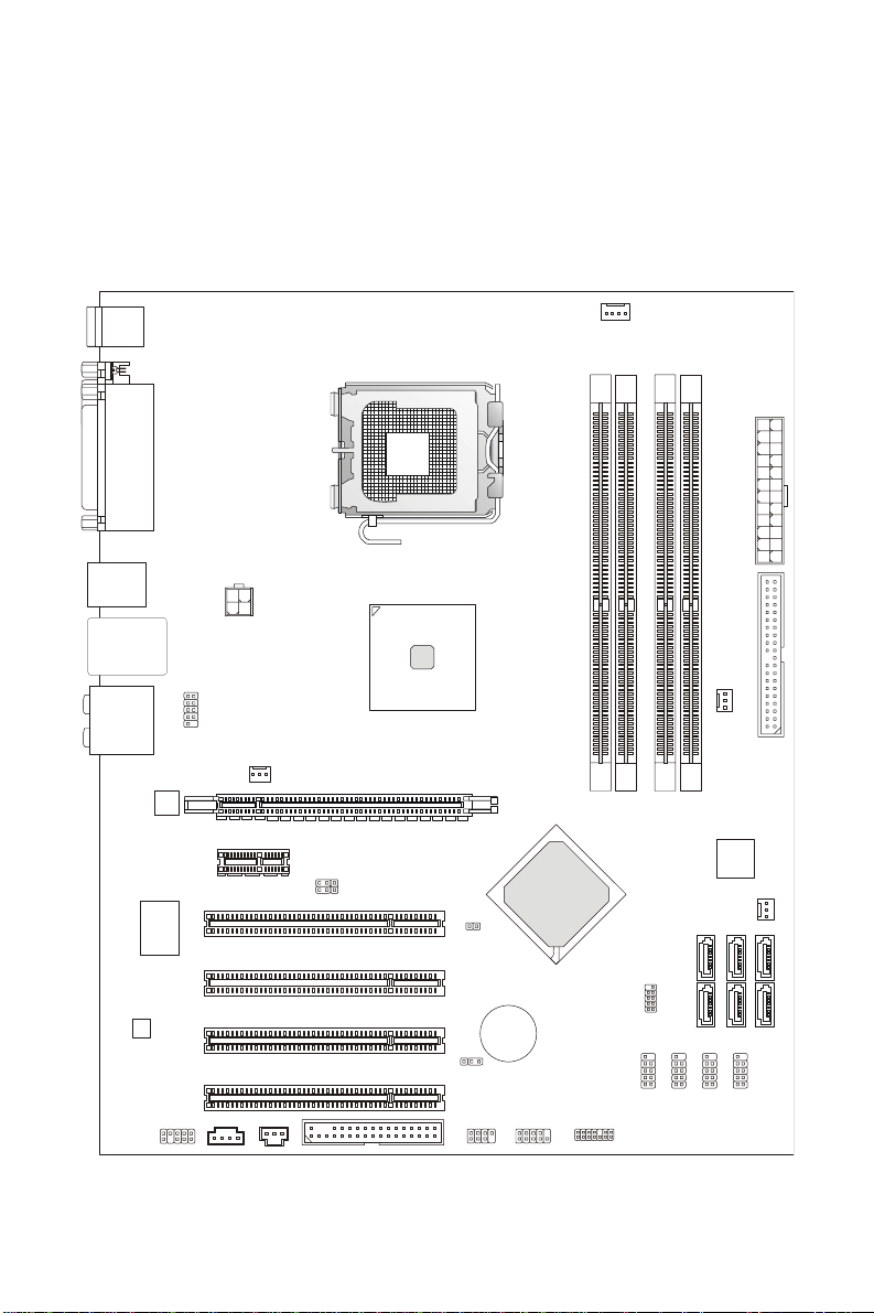
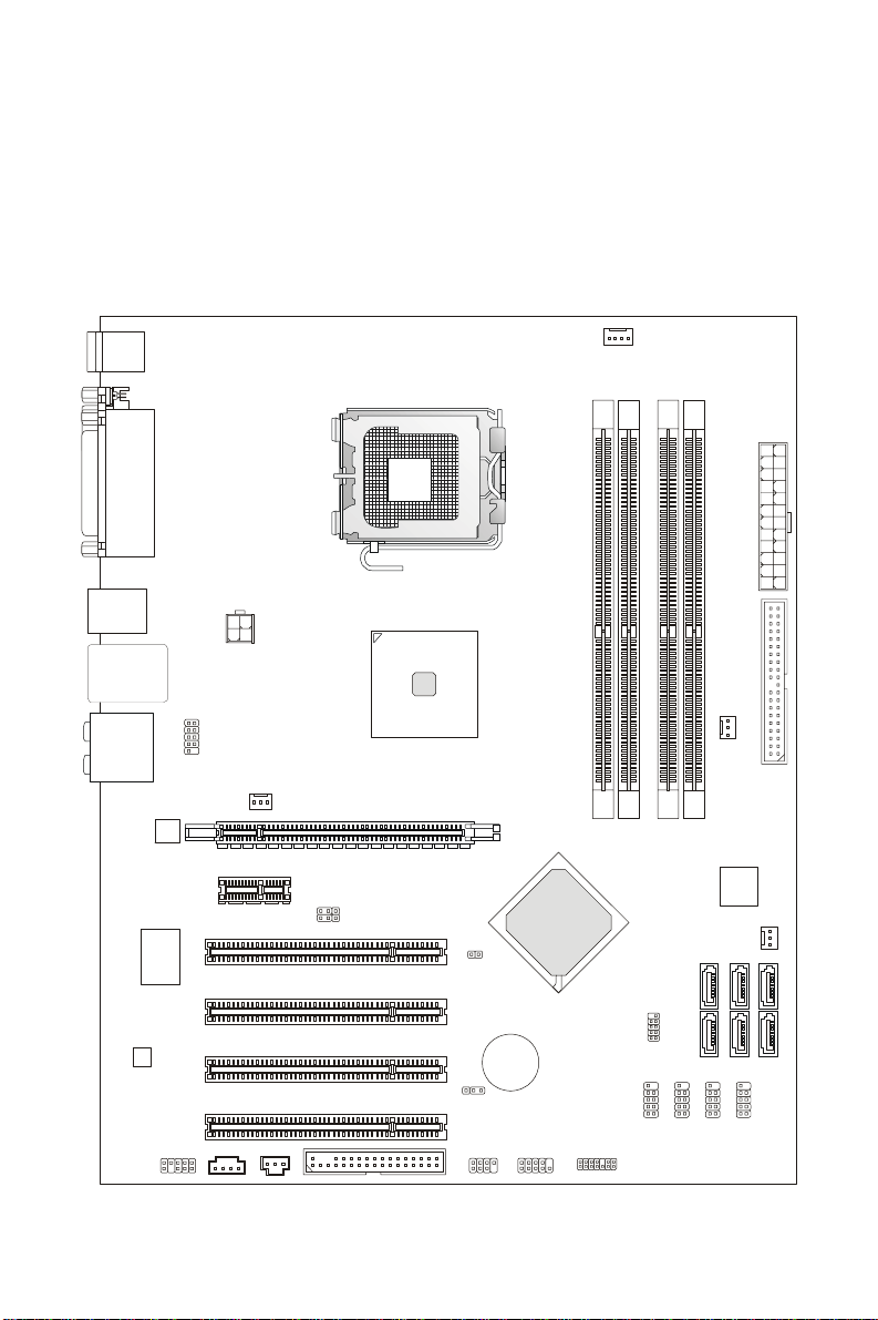
Layout
Top : mouse
Bottom:
keyboard
Top :
Parallel Port
Bottom:
COM port
USB ports
JAUD1
JCOM1
CD_IN1
JPW1
SYSFAN1
PCI_E2
PCI 4
PCI 3
PCI 2
PCI 1
JSPD1
Top: LAN Jack
Bottom: USB ports
Line-In
T:
Line-Out
M:
Mic
B:
T:R S-Ou t
M:CS-Out
B:SS-Out
RTL8111B
Super I/O
FINTEK/F71882FG
LC888
®
P35 & ICH9 chipsets for optimal system efficiency.
®
Core 2 Quad/Core 2 Duo/Pentium/Celeron LGA775
CPUFAN1
Intel
P35
1
2
A
A
_
_
M
PCI_E1
FDD1
JB2
JB1
JCI1
JBAT1
JFP2
BATT
+
JFP1
Intel
ICH9
M
M
M
I
I
D
D
JTPM1(optional)
3
R
W
P
J
1
E
D
I
3
N
A
F
S
Y
S
1
2
B
B
_
_
M
M
M
M
I
I
D
D
2
4
A
A
T
T
A
A
S
S
1
I
P
S
1
3
J
A
A
T
T
A
A
S
S
4
3
1
2
B
B
S
U
J
B
B
S
S
S
U
U
U
J
J
J
2
N
A
F
S
Y
S
6
A
T
A
S
5
A
T
A
S
1

SPECIFICATIONS
Processor Support
z Intel® Core 2 Quad/Core 2 Duo/Pentium/Celeron processors in the LGA775 package
z Support Intel
(For the latest information about CPU, please visit
http://global.msi.com.tw/index.php?func=cpuform)
Supported FSB
z 1333/ 1066 / 800 MHz
Chipset
z North Bridge: Intel® P35 chipset
z South Bridge: Intel
Memory Support
z DDR2 1066/ 800/ 667 SDRAM (8GB Max)
z 4 DDR2 DIMMs (240pin/ 1.8V)
(For more information on compatible components, please visit
http://global.msi.com.tw/index.php?func=testreport)
LAN
z Supports 10/100/1000 Fast Ethernet by RTL8111B
Audio
z Chip integrated by Realtek® ALC888
z Flexible 8-channel audio with jack sensing
z Compliant with Azalia 1.0 Spec
z Meet Microsoft Vista Premium spec
®
Yorkfield, Wolfdale
®
ICH9 chipset
IDE
z 1 IDE port by JMicron JMB363
z Supports Ultra DMA 66/100/133 mode
z Supports PIO, Bus Master operation mode
SATA
z 4 SATA II ports by ICH9.
z 2 SATAII ports by JMicron JMB363.
z Supports storage and data transfers at up to 300 MB/s
RAID
z Supports RAID 0, 1 and JBOD by JMicron JMB363. (SATA5, SATA6).
Floppy
z 1 floppy port
z Supports 1 FDD with 360KB, 720KB, 1.2MB, 1.44MB and 2.88MB
2

Connectors
z Back panel
- 1 PS/2 mouse port
- 1 PS/2 keyboard port
- 1 serial port (COM1)
- 1 parallel port supporting SPP/EPP/ECP mode
- 4 USB 2.0 Ports
- 1 LAN jack (10/100/1000)
- 6 flexible audio jacks
z On-Board Pinheaders / Connectors
- 4 USB 2.0 pinheaders
- 1 CD-In connector
- 1 Front Panel Audio pinheader
- 1 TPM pinheader(optional)
- 1 SPDIF-Out pinheader
- 1 Serial port connector
- 1 Chassis Intrusion Switch pinheader
Slots
z 1 PCI Express x16 slot
z 1 PCI Express x1 slot
z 4 PCI slots
z Support 3.3V/ 5V PCI bus Interface
Form Factor
z ATX (30.5cm X 24.5cm)
Mounting
z 9 mounting holes
3
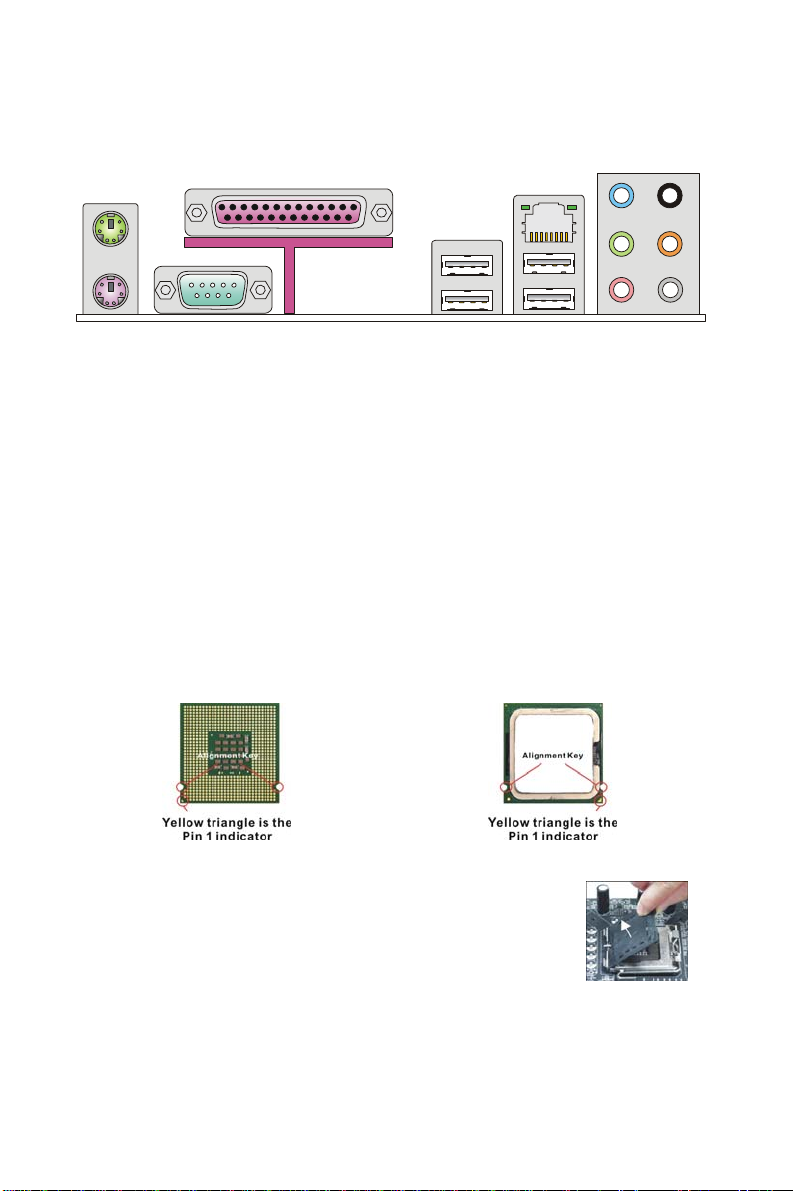
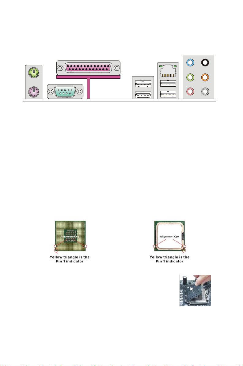
REAR PANEL
y
t
The rear panel provides the following connectors:
Mouse
Parallel Port
LAN
Line-In
RS-Out
CS-Ou
SS-Out
Ke
board
Serial port USB ports
Line-Out
MIC
HARDWARE SETUP
This chapter tells you how to install the CPU, memory modules, and expansion cards, as
well as how to setup the jumpers on the mainboard. It also provides the instructions on
connecting the peripheral devices, such as the mouse, keyboard, etc. While doing the
installation, be careful in holding the components and follow the installation procedures.
CPU & Cooler Installation Procedures for LGA775
When you are installing the CPU, make sure the CPU has a cooler attached on the top to
prevent overheating. Meanwhile, do not forget to apply some thermal paste on CPU before
installing the heat sink/cooler fan for better heat dispersion.
Follow the steps below to install the CPU & cooler correctly. Wrong installation will ca use the
damage of your CPU & mainboard.
Introduction to LGA 775 CPU
The pin-pad side of LGA 775 CPU.
1. The CPU socket has a plastic cap on it to protect the contact
from damage. Before you have installed the CPU, always
cover it to protect the socket pin.
2. Remove the cap from lever hinge side.
3. The pins of socket reveal.
4. Open the load lever.
5. Lift the load lever up and open the load plate.
The surface of LGA 775 CPU.
4

6. After confirming the CPU direction for correct mating, put
down the CPU in the socket housing frame. Be sure to grasp
on the edge of the CPU base. Note that the alignment keys
are matched.
7. Visually inspect if the CPU is seated well into the socket. If
not, take out the CPU with pure vertical motion and reinstall.
8. Cover the load plate onto the package.
9. Press down the load lever lightly onto the load plate, and
then secure the lever with the hook under retention tab.
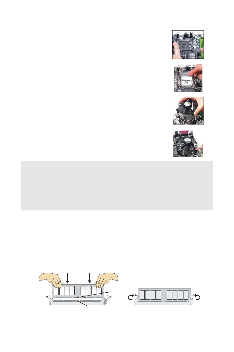
10. Align the holes on the mainboard with the cooler. Push down
the cooler until its four clips get wedged into the holes of the
mainboard.
11. Press the four hooks down to fasten the cooler. Then rotate
the locking switch (refer to the correct direction marked on it)
to lock the hooks.
12. Turn over the mainboard to confirm that the clip-ends are
correctly inserted.
Important:
Read the CPU status in BIOS.
Whenever CPU is not installed, always protect your CPU socket pin with the plastic cap
covered to avoid damaging.
Mainboard photos shown in this section are for demonstration of the CPU/cooler installation
only. The appearance of your mainboard may vary depending on the model you purchase.
Installing Memory Modules
1. The memory module has only one notch on the center and will only fit in the right
orientation.
2. Insert the memory module vertically into the DIMM slot. Then push it in until the
golden finger on the memory module is deeply inserted in the DIMM slot. You can
barely see the golden finger if the memory module is properly inserted in the DIMM
slot.
3. The plastic clip at each side of the DIMM slot will automatically close.
Notch
Volt
5
Important:
#
V
DDR2 memory modules are not interchangeable with DDR and the DDR2 standard is not
backwards compatible. You should always install DDR2 memory modules in the DDR2
DIMM slots.
To enable successful system boot-up, always insert the memory modules into the DIMM1
first.
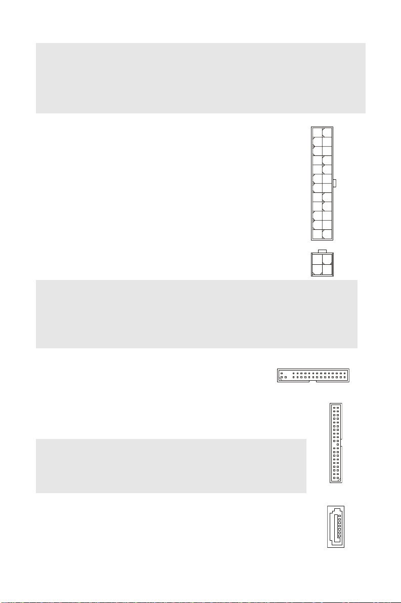
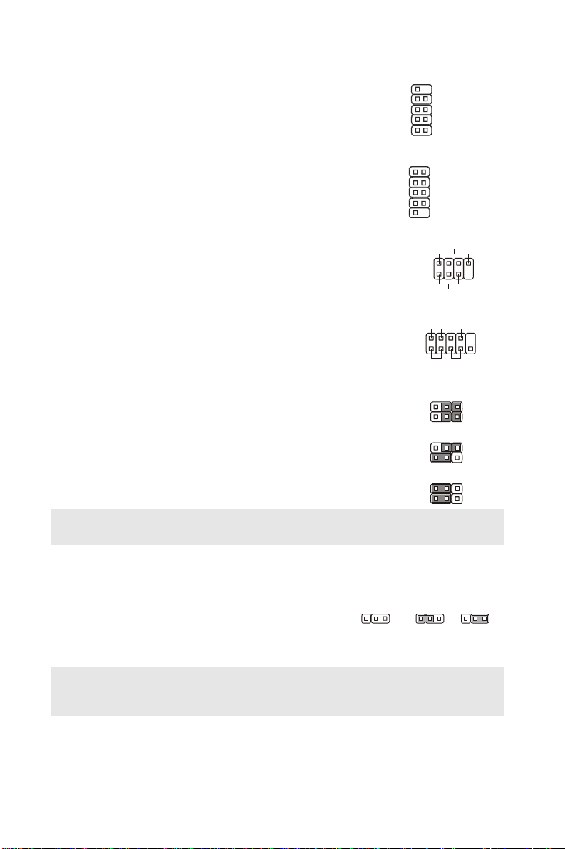
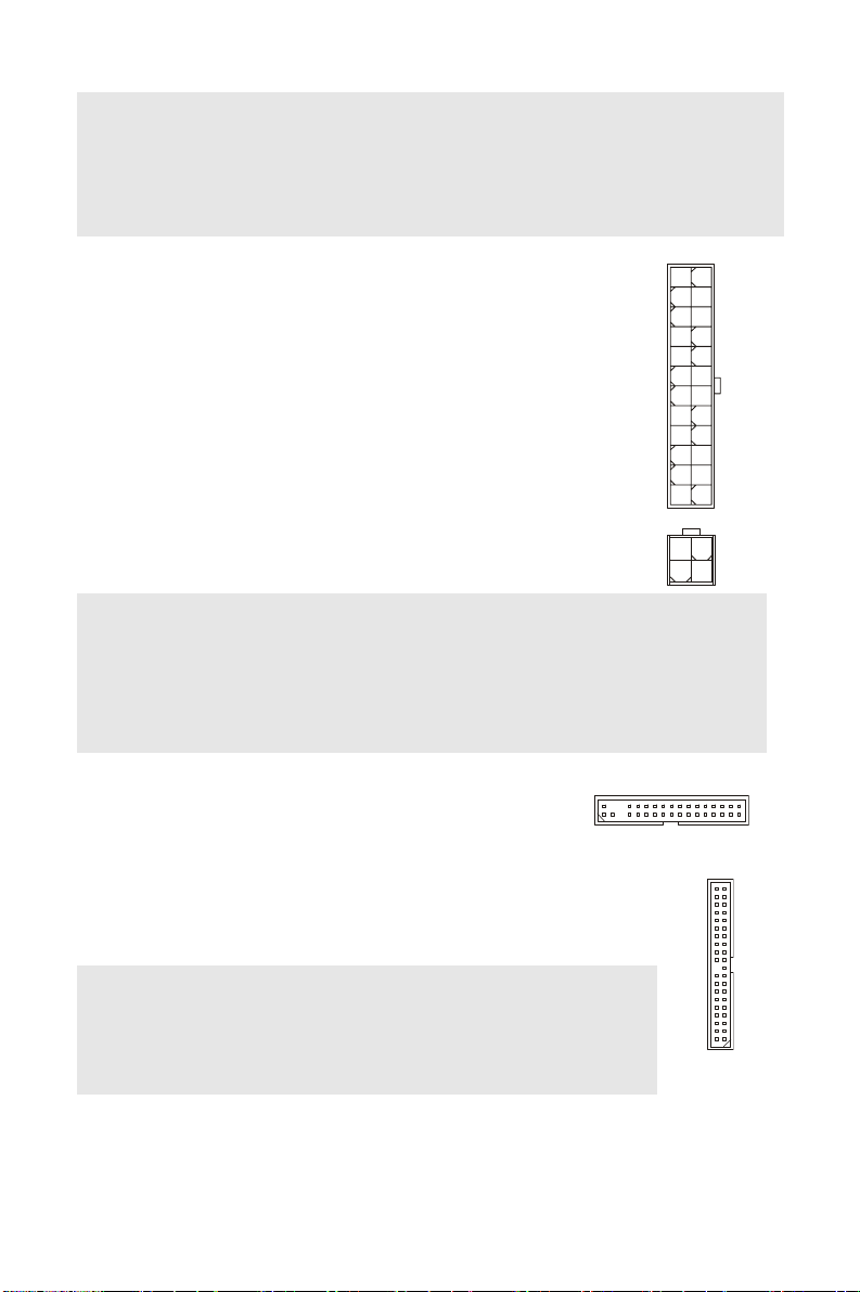
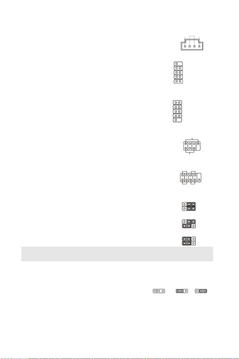
ATX 24-Pin Power Connector: JPWR3
This connector allows you to connect an ATX 24-pin power supply.
To connect the ATX 24-pin power supply, make sure the plug of the
power supply is inserted in the proper orientation and the pins are
aligned. Then push down the power supply firmly into the
connector.
You may use the 20-pin ATX power supply as you like. If you like to
use the 20-pin ATX power supply, please plug your power supply
along with pin 1 & pin 13 (refer to the image at the right hand).
ATX 12V Power Connector: JPW1
This 12V power connector is used to provide power to the CPU.
+3.3V
+12V
+12V
5VSB
PWR OK
GND
+5V
GND
+5V
GND
+3.3V
+3.3V
+12V +12
GND GND
GND
+5V
+5V
+5V
Res
GND
GND
GND
PS-ON
GND
-12V
+3.3V
Important:
Make sure that all the connectors are connected to proper ATX power supplies to ensure
stable operation of the mainboard.
Power supply of 350 watts (and above) is highly recommended for system stability.
ATX 12V power connection should be greater than 18A.
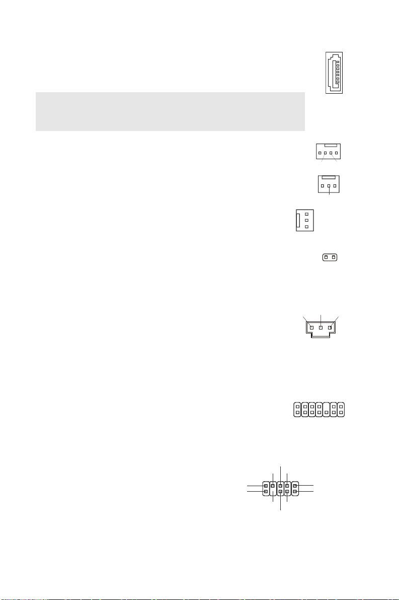
Floppy Disk Drive Connector: FDD1
This connector supports 360KB, 720KB, 1.2MB, 1.44MB or
2.88MB floppy disk drive.
IDE Connector: IDE1
This connector supports IDE hard disk drives, optical disk drives and other
IDE devices.
Important:
If you install two IDE devices on the same cable, you must configure the
drives to cable select mode or separately to master / slave mode by setting
jumpers. Refer to IDE device documentation supplied by the vendors for
jumper setting instructions.
Serial A TA Connector: SA TA1~6
This connector is a high-speed Serial ATA interface port. Each connector
can connect to one Serial ATA device.
6

Important:
D
r
D
S
B
3
Li
R
G
Please do not fold the Serial ATA cable into 90-degree angle. Otherwise,
data loss may occur during transmission.
Fan Power Connectors: CPUFAN1,
SYSFAN1~3
The fan power connectors support system cooling fan with +12V.
When connecting the wire to the connectors, always note that the red
wire is the positive and should be connected to the +12V; the black
wire is Ground and should be connected to GND. If the mainboard
has a System Hardware Monitor chipset on-board, you must use a
specially designed fan with speed sensor to take advantage of the
CPU fan control.
Chassis Intrusion Connector: JCI1
This connector connects to the chassis intrusion switch cable. If the
chassis is opened, the chassis intrusion mechanism will be activated.
The system will record this status and show a warning message on
the screen. To clear the warning, you must enter the BIOS utility and
clear the record.
S/PDIF-Out Connector: JSPD1
This connector is used to connect S/PDIF (Sony & Philips Digital
Interconnect Format) interface for digital audio transmission.
TPM Module connector: JTPM1(optional)
This connector connects to a TPM (Trusted Platform Module)
module (optional). Please refer to the TPM security platform
manual for more details and usages.
Front Panel Audio
Connector: JAUD1
This connector allows you to connect the
front panel audio and is compliant with
®
Intel
Front Panel I/O Connectivity Design
Guide.
Front to Sense
(9)Line-out_L
(10)Line_JD
ne-out_
NC
MIC2_JD
CD-In Connector: CD_IN1
This connector is provided for external audio input.
Control
Sensor
Sensor
GND
+12V
Senso
CINTRU GN
PDIF
GND VCC
T
S
_
V
3
/
l
a
3
u
Q
C
d
R
I
C
V
S
3
V
2
1
#
0
K
T
L
D
S
C
A
L
L
R
L
MIC_R
MIC_L(1)
GND(2)
VCC5
ND
+12V
5
C
C
V
1
D
A
L
Y
E
K
2
D
A
L
+12V
21
D
N
G
3
D
A
L
LR
GND
GN
D
N
G
14
1
#
E
M
A
R
F
L
7
Front USB Connector: JUSB1~4
0
9
S
S
P
0
a
This connector, compliant with Intel® I/O Connectivity
Design Guide, is ideal for connecting high-speed USB
interface peripherals such as USB HDD, digital cameras,
MP3 players, printers, modems and the like.
Serial Port Connector: JCOM1
This connector is a 16550A high speed communication
port that sends/receives 16 bytes FIFOs. You can attach
a serial device.
Front Panel Connectors: JFP1,
JFP2
USB1+
JFP2
N.C.
GND
USB1-
VCC
DCD
SOUT
GND
RTS
These connectors are for electrical connection to the
front panel switches and LEDs. The JFP1 is compliant
with Intel
®
Front Panel I/O Connectivity Design Guide.
JFP1
Hardware Overclock FSB Jumpers:
200MHz
JB1, JB2 (optional)
You can overclock the FSB to increase the processor
frequency by changing the jumpers JB1 and JB2. Follow
the instructions below to set the FSB.
Important:
Make sure that you power off the system before changing the jumpers
266MHz
333MHz
10
9
Key,n o pin
GND
USB0+
USB0VCC
2
1
2
1
SIN
DTR
DSR
CTS
Key,no pin
RI
1
peaker
2
17
Power LED
Power
Switch
LED
+
2
1
+
-
HDD
Reset
LED
witch
13
13
13
8
ower
-
+-
JB2
JB1
JB2
JB1
JB2
JB1
1
9
Clear CMOS Jumper: JBAT1
There is a CMOS RAM onboard that has a power supply
from an external battery to keep the data of system
configuration. With the CMOS RAM, the system can
automatically boot OS every time it is turned on. If you
want to clear the system configuration, set the jumper to
223311123
Keep Data Clear Dat
clear data.
Important:
You can clear CMOS by shorting 2-3 pin while the system is off. Then return to 1-2 pin
position. Avoid clearing the CMOS while the system is on; it will damage the mainboard.
PCI (Peripheral Component Interconnect) Express Slot
The PCI Express slot supports the PCI Express interface expansion card.
8
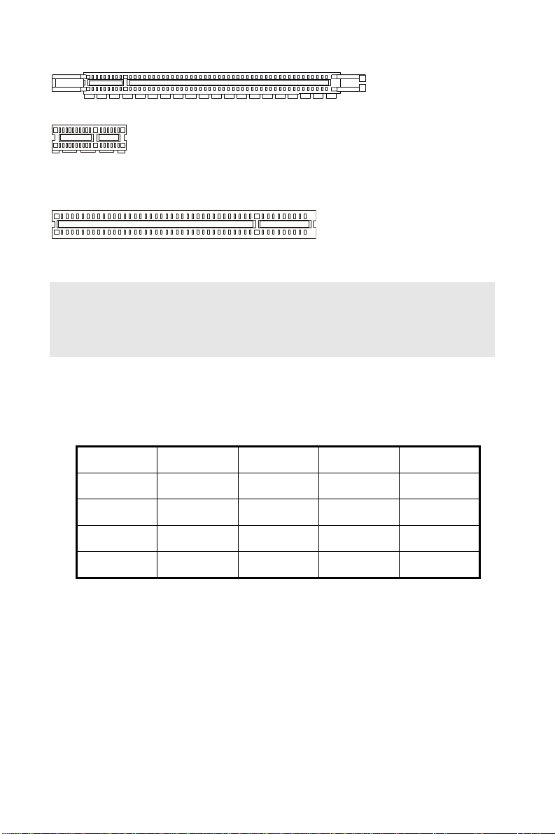
The PCI Express x 16 slot supports up to 4.0 GB/s transfer rate.
The PCI Express x 1 slot supports up to 250 MB/s transfer rate.
PCI (Peripheral Component Interconnect) Slot
The PCI slot supports LAN card, SCSI card, USB card, and other add-on cards that
comply with PCI specifications.
Important:
When adding or removing expansion cards, make sure that you unplug the power supply
first. Meanwhile, read the documentation for the expansion card to configure any
necessary hardware or software settings for the expansion card, such as jumpers,
switches or BIOS configuration.
PCI Interrupt Request Routing
The IRQ, acronym of interrupt request line and pronounced I-R-Q, are hardware lines over
which devices can send interrupt signals to the microprocessor. The PCI IRQ pins are
typically connected to the PCI bus pins as follows:
Order1 Order2 Order3 Order4
PCI Slot1 INT B# INT C# INT D# INT A#
PCI Slot2 INT A# INT B# INT C# INT D#
PCI Slot3 INT C# INT D# INT A# INT B#
PCI Slot4 INT D# INT A# INT B# INT C#
9

BIOS Setup
Power on the computer and the system will start POST (Power On Self Test) process. When
the picture below appears on the screen, press <F2> or <DEL> key to enter Setup.
If the message disappears before you respond and you still wish to enter Setup, restart the
system by turning it OFF and On or pressing the RESET button. You may also restart the
system by simultaneously pressing <Ctrl>, <Alt>, and <Delete> keys.
10

Main Page
System Status
These items show the status and memory size of your system and allow you to adjust the
system time, date etc.
Cell Menu
Use this menu to specify your settings for frequency/voltage control and overclocking.
Chipset Setting
Use this menu to specify your settings for chipset features.
Boot Setting
Use this menu to specify your settings for boot configuration.
Password Setting
Use this menu to set the password for BIOS.
Save & Exit
Use this menu to save or restore the changes.
11
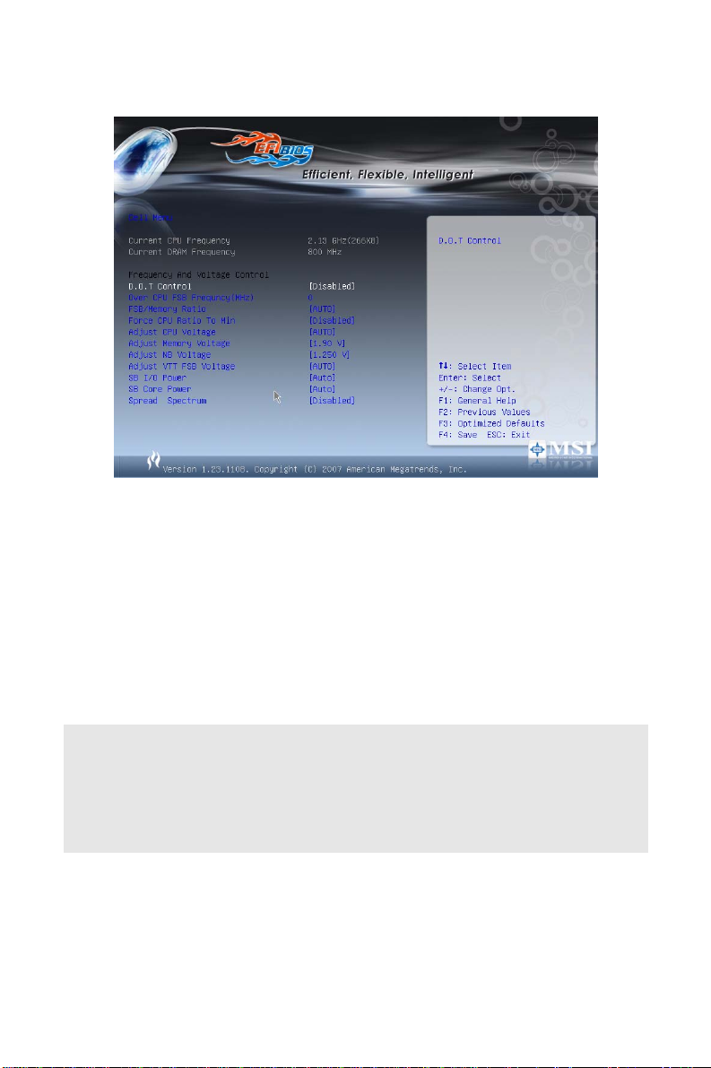
Cell Menu
Current CPU/DRAM Frequency
It shows the current frequency of CPU/DRAM. Read-only.
D.O.T Control
This item allows users to enable/disable the D.O.T. The D.O.T. (Dynamic Overclocking
Technology) is an automatic overclocking function, included in the MSITM newly developed
Dual CoreCellTM Technology. It is designed to detect the load balance of CPU while running
programs, and to adjust the best frequency automatically. When the motherboard detects
system is running programs, it will speed up automatically to make the program run
smoothly and faster. When the system is temporarily suspending or staying in the low load
balance, it will restore the default settings instead. Usually the Dynamic Overclocking
Technology will be powered only when users' PC need to run huge amount of data like 3D
games or the video process, and the CPU frequency need to be boosted up to enhance
the overall performance.
Important:
Even though the Dynamic Overclocking Technology is more stable than manual
overclocking, basically, it is still risky. We suggest user to make sure that your CPU can
afford to overclocking regularly first. If you find the PC appears to be unstable or reboot
incidentally, it's better to disable the Dynamic Overclocking or to lower the level of
overclocking options. By the way, if you need to conduct overclocking manually, you also
need to disable the Dynamic OverClocking first.
Over CPU FSB Frequency (MHz)
The items specify the clock frequency of CPU host bus (FSB). They provide a method for
end users to overclock the process.
FSB/Memory Ratio
This item will allow you to adjust the FSB/Ratio of the memory.
12

Adjust CPU Voltage
This item will allow you to adjust the CPU voltage.
Adjust Memory Voltage
This item will allow you to adjust the memory voltage.
Adjust NB Voltage
This item will allow you to adjust the north bridge voltage.
Adjust VTT FSB Voltage
This item will allow you to adjust the VTT FSB voltage.
SB I/O Power
This item will allow you to adjust the south bridge I/O voltage.
SB Core Power
This item will allow you to adjust the south bridge core voltage.
Spread Spectrum
When the motherboard’s clock generator pulses, the extreme values (spikes) of the pulses
create EMI (Electromagnetic Interference). The Spread Spectrum function reduces the EMI
generated by modulating the pulses so that the spikes of the pulses are reduced to flatter
curves. If you do not have any EMI problem, leave the setting at Disabled for optimal system
stability and performance. But if you are plagued by EMI, set to Enabled for EMI reduction.
Remember to disable Spread Spectrum if you are overclocking because even a slight jitter
can introduce a temporary boost in clock speed which may just cause your overclocked
processor to lock up.
Important:
If you do not have any EMI problem, leave the setting at [Disabled] for optimal system
stability and performance. But if you are plagued by EMI, select the value of Spread
Spectrum for EMI reduction.
The greater the Spread Spectrum value is, the greater the EMI is reduced, and the system
will become less stable. For the most suitable Spread Spectrum value, please consult your
local EMI regulation.
Remember to disable Spread Spectrum if you are overclocking because even a slight jitter
can introduce a temporary boost in clock speed which may just cause your overclocked
processor to lock up.
13
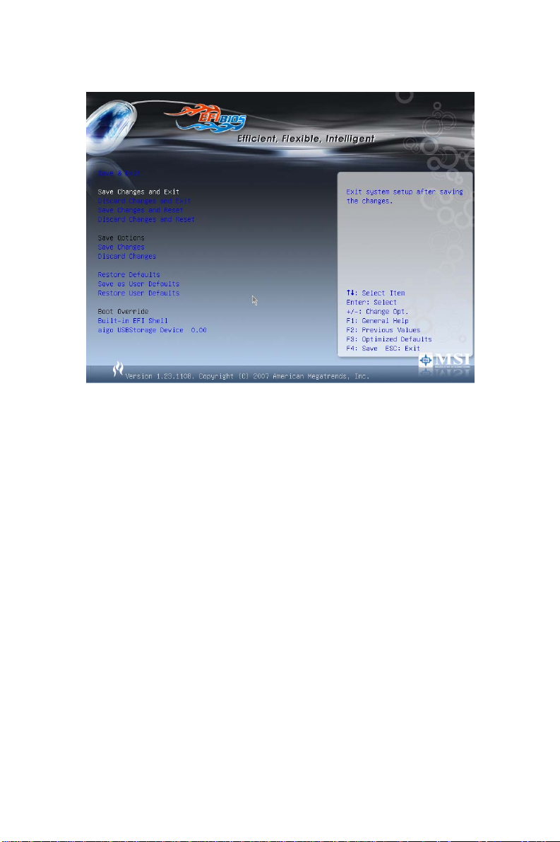
Save and Exit
Save Changes and Exit
Use this item to save changes and exit setup.
Discard Changes and Exit
Use this item to abandon all changes and exit setup.
Save Changes and Reset
Use this item to save changes and reset the computer.
Discard Changes and Reset
Abandon all changes and reset the computer.
Save Changes
Use this item to save changes.
Discard Changes
Use this item to abandon all changes.
Restore Defaults
Use this item to load the default values set by the BIOS vendor.
Save as User Defaults / Restore User Defaults
You can use these items to backup BIOS settings or restore the system back to the
particular operation status in the event it encountered problems.
14
소개
A
EFINITY 시리즈 (MS-7395 v1.X) ATX 메인보드를 선택해주셔서 감사합니다.
EFINITY 시리즈 메인보드는 최적의 시스템 효율을 위해 Intel
탑재했습니다. 고급의 Intel
®
Core 2 Quad/Core 2 Duo/Pentium/Celeron LGA775
프로세서에 적합하게 디자인된 EFINITY 시리즈는 고성능 및 전문가용 데스크톱 플랫폼
솔루션을 제공합니다.
레이아웃
Top : mouse
Bottom:
keyboard
Top :
Parallel Port
Bottom:
COM port
USB ports
Top: LAN Jack
Bottom: USB ports
Line-In
T:
Line-Out
M:
Mic
B:
T:R S-Ou t
M:CS-Out
B:SS-Out
RTL8111B
Super I/O
FINTEK/F71882FG
LC888
JAUD1
JCOM1
CD_IN1
JPW1
SYSFAN1
PCI_E2
PCI 4
PCI 3
PCI 2
PCI 1
JSPD1
PCI_E1
FDD1
JB2
JB1
Intel
P35
15
JCI1
JBAT1
JFP2
BATT
+
®
P35 및 ICH9 칩셋을
1
A
_
M
M
I
D
Intel
ICH9
JTPM1(optional)
JFP1
CPUFAN1
2
A
_
M
M
I
D
3
R
W
P
J
1
E
D
I
3
N
A
F
S
Y
S
1
2
B
B
_
_
M
M
M
M
I
I
D
D
2
4
A
A
T
T
A
A
S
S
1
I
P
S
1
3
J
A
A
T
T
A
A
S
S
4
3
1
2
B
B
S
U
J
B
B
S
S
S
U
U
U
J
J
J
2
N
A
F
S
Y
S
6
A
T
A
S
5
A
T
A
S

사양
지원 프로세서
z LGA775 패키지의 Intel® Core 2 Quad/Core 2 Duo/Pentium/Celeron 프로세서
®
z Intel
지원되는 FSB
z 1333/ 1066 / 800 MHz
칩셋
z North Bridge: Intel® P35 칩셋
z South Bridge: Intel
메모리 지원
z DDR2 1066/ 800/ 667 SDRAM (최대 8GB)
z 4 DDR2 DIMMs (240pin/ 1.8V)
LAN
z RTL8111B 에 의한 10/100/1000 Fast Ethernet 지원
오디오
z Realtek® ALC888 에 통합된 칩
z 잭 감지 기능이 있는 플렉시블 8채널 오디오
z Azalia 1.0 사양 준수
z Microsoft Vista Premium 사양 충족
Yorkfield, Wolfdale 지원
(CPU의 최신 정보는
(호환 부품에 대한 자세한 내용은
참조하십시오.)
http://global.msi.com.tw/index.php?func=cpuform 을 참조하십시오.)
®
ICH9 칩셋
http://global.msi.com.tw/index.php?func=te streport 를
IDE
z JMicron JMB363 에 의한 1개의 IDE 포트
z Ultra DMA 66/100/133 모드 지원
z PIO, Bus Master 작동 모드 지원
SATA
z ICH9 에 의한 4개의 SATA II 포트
z JMicron JMB363 에 의한 2개의 SATA II 포트
z 최대 300 MB/s 속도의 저장 및 데이터 전송 지원
RAID
z JMicron JMB363 에 의한 RAID 0, 1 및 JBOD 지원(SATA5, SATA6).
플로피
z 1개의 플로피 포트
z 360KB, 720KB, 1.2MB, 1.44MB 및 2.88MB 의 FDD 1 개 지원
16

커넥터
z 후면판
- 1 개의 PS/2 마우스 포트
- 1 개의 PS/2 키보드 포트
- 1 개의 직렬 포트(COM1)
- SPP/EPP/ECP 모드를 지원하는 1개의 병렬 포트
- 4 개의 USB 2.0 포트
- 1 개의 LAN 잭(10/100/1000)
- 6 개의 플렉시블 오디오 잭
z 온보드 핀헤더/커넥터
- 4 개의 USB 2.0 핀헤더
- 1 개의 CD 입력 커넥터
- 1 개의 전면판 오디오 핀헤더
- 1 개의 TPM 핀헤더(옵션)
- 1 개의 SPDIF 출력 핀헤더
- 1 개의 직렬 포트 커넥터
- 1 개의 섀시 침입 스위치 핀헤더
슬롯
z 1개의 PCI Express x16 슬롯
z 1개의 PCI Express x1 슬롯
z 4개의 PCI 슬롯
z 3.3V/ 5V PCI 버스 인터페이스 지원
폼 팩터
z ATX (30.5cm X 24.5cm)
장착
z 9개의 장착 구멍
17
백패널
y
t
백패널에 있는 커넥터:
Mouse
Parallel Port
LAN
Line-In
RS-Out
CS-Ou
SS-Out
Ke
board
Serial port USB ports
Line-Out
MIC
하드웨어 설치
여기에서 CPU, 메모리 모듈, 확장 카드를 설치하는 방법과 메인보드에서 점퍼를
설정하는 방법을 설명합니다. 또한 마우스, 키보드 등과 같은 주변 장치를 연결하는
방법을 설명합니다. 설치 시 구성 부품을 주의해서 취급하고 설치 절차를 따르십시오.
LGA775 의 CPU 및 쿨러 설치 절차
CPU 설치 시, 과열을 방지하는 쿨러가 CPU 상단에 부착되어 있어야 합니다. 한편
효과적인 열 분산을 위해 방열판/쿨러 팬을 설치하기 전에 반드시 CPU 에 약간의
열전도용 열 페이스트를 바르십시오.
아래의 단계에 따라 CPU 및 쿨러를 올바로 설치하십시오. 제대로 설치하지 않는 경우
CPU 및 메인보드가 손상됩니다.
LGA 775 CPU 의 소개
LGA 775 CPU의 핀 패드 면
1. CPU 소켓에 플라스틱 캡이 씌워져 있어 접촉에 의한
손상을 방지합니다. CPU 를 설치하기 전에, 항상 캡을
씌워 소켓 핀을 보호하십시오.
2. 레버 힌지 쪽에서 캡을 제거합니다.
3. 소켓의 핀이 드러납니다.
4. 로드 레버를 엽니다.
5. 로드 레버를 들어올려 로드 플레이트를 엽니다.
18
LGA 775 CPU의 표면
6. 올바로 물리는지 CPU 방향을 확인한 다음 down the
CPU 를 소켓 하우징 프레임에 눌러 끼웁니다. 반드시
CPU 베이스의 가장자리를 잡으십시오. 정렬 키가
일치하는지 확인하십시오.
7. CPU 가 소켓에 올바로 끼워졌는지 육안으로 확인합니다.
그렇지 않은 경우, CPU 를 수직으로 뽑은 다음 다시
설치합니다.
8. 로드 플레이트로 패키지를 덮습니다.
9. 로드 레버를 로드 플레이트 쪽으로 가볍게 누른 다음
리텐션 탭 아래의 훅으로 레버를 고정합니다.
10. 메인보드의 구멍을 쿨러에 맞춥니다. 쿨러의 클립 4개가
메인보드의 구멍에 완전히 끼워질 때까지 쿨러를 아래로
누릅니다.
11. 4 개의 훅을 눌러 쿨러를 고정합니다. 그리고 나서 잠금
스위치를 회전하여(스위치에 표시된 방향 참조) 훅을
잠급니다.
12. 메인보드를 뒤집어 클립의 끝이 올바로 끼워졌는지
확인합니다.
중요:
BIOS 에서 CPU 상태를 확인하십시오.
CPU 가 설치되지 않은 경우에는 손상을 방지하기 위해 플라스틱 캡으로 덮어 CPU
소켓 핀을 보호하십시오,
이 절에 사용된 메인보드 사진은 오직 CPU/쿨러 설치를 예로 보여주기 위함입니다.
메인보드의 실제 외양은 구입한 모델에 따라 다를 수 있습니다.
메모리 모듈의 설치
1. 메모리 모듈은 중앙에 노치가 하나 있으며 오른쪽 방향으로만 끼워집니다.
2. 메모리 모듈을 DIMM 슬롯에 수직으로 끼웁니다. 그리고 나서 메모리 모듈의 골든
핑거가 DIMM 슬롯에 완전히 끼워질 때까지 모듈을 안쪽으로 밉니다. 메모리 모듈이
DIMM 슬롯에 올바로 끼워진 경우 골든 핑거가 보일 듯 말 듯 합니다.
3. DIMM 슬롯의 측면에 있는 플라스틱 클립이 자동으로 닫힙니다.
Notch
Volt
19
중요:
#
V
DDR2 메모리는 DDR 과 호환되지 않으며 DDR2 표준은 역 호환되지 않습니다. DDR2
DIMM 슬롯에는 항상 DDR2 메모리 모듈만 설치해야 합니다.
시스템이 성공적으로 부팅되도록 하기 위해, 항상 메모리 모듈을 DIMM1 에 먼저
끼우십시오.
ATX 24 핀 전원 커넥터: JPWR3
이 커넥터를 사용하여 AT X 24 핀 전원 공급장치를 연결할 수
있습니다. ATX 24 핀 전원 공급장치를 연결하려면, 전원
공급장치의 플러그가 올바른 방향으로 끼워지고 핀이 올바로
맞추어졌는지 확인하십시오. 그리고 나서 전원 공급장치를
커넥터 쪽으로 완전히 누르십시오.
원하는 경우 20 핀 ATX 전원 공급장치를 사용할 수도 있습니다.
핀 ATX 전원 공급장치를 사용하려는 경우, 핀 1과 핀 13 에
전원 공급장치를 플러그로 연결하십시오(오른쪽 그림 참조).
ATX 12V 전원 커넥터: JPW1
이 12V 전원 커넥터는 CPU 에 전원을 공급하는 데 사용됩니다.
+3.3V
+12V
+12V
5VSB
PWR OK
GND
+5V
GND
+5V
GND
+3.3V
+3.3V
+12V +12
GND GND
GND
+5V
+5V
+5V
Res
GND
GND
GND
PS-ON
GND
-12V
+3.3V
중요:
메인보드가 올바로 작동할 수 있도록 모든 커넥터가 올바른 ATX 전원 공급장치에
연결되었는지 확인하십시오.
시스템의 안정성을 위해 350 와트 이상의 전원 공급장치를 권장합니다.
ATX 12V 전원 연결은 전류가 18A 이상이어야 합니다.
플로피 디스크 드라이브 커넥터: FDD1
이 커넥터는 360KB, 720KB, 1.2MB, 1.44MB 또는 2.88MB
플로피 디스크 드라이브를 지원합니다.
IDE 커넥터: IDE1
이 커넥터는 IDE 하드 디스크 드라이버, 광디스크 드라이브 및 기타
IDE 장치를 지원합니다.
중요:
동일한 케이블에 2대의 IDE 장치를 설치하는 경우 드라이브를 케이블
선택 모드로 구성하거나, 점퍼 설정을 통해 개별적으로 마스터/슬레이브
모드를 구성해야 합니다. 점퍼 설정 방법은 판매업체가 제공한 IDE
장치 설명서를 참조하십시오.
20
직렬 ATA 커넥터: SATA1~6
D
r
D
S
B
3
Li
R
이 커넥터는 고속의 직렬 ATA 인터페이스 포트입니다. 각 커넥터를
하나의 직렬 ATA 장치에 연결할 수 있습니다.
중요:
직렬 ATA 케이블이 90 도로 꺾이지 않도록 주의하십시오. 그러지 않을
경우 전송 중 데이터가 손실될 수 있습니다.
팬 전원 커넥터: CPUFAN1, SYSFAN1~3
팬 전원 커넥터는 +12V 의 시스템 냉각 팬을 지원합니다. 전선을
커넥터에 연결할 때, 빨간색 전선이 양극으로서 +12V 에 연결해야
하며, 검은색 전선이 접지용으로 GND 에 연결해야 합니다.
메인보드에 시스템 하드웨어 모니터 칩
되어있는경우
센서가 있는 팬을 사용해야 합니다
. CPU 팬 제어
기능을 사용을 위해 속도제어
.
셋이
온보드
섀시 침입 커넥터: JCI1
이 커넥터는 섀시 침입 스위치 케이블에 연결됩니다. 섀시가
열리는 경우, 섀시 침입 메커니즘이 작동합니다. 시스템이 이
상태를 기록하며 화면에 경고 메시지를 표시합니다. 경고 메시지를
지우려면, BIOS 유틸리티를 시작하여 기록을 지워야 합니다.
S/PDIF 출력 커넥터: JSPD1
이 커넥터는 디지털 오디오 전송용 S/PDIF (Sony & Philips Digital
Interconnect Format) 인터페이스를 연결하는 데 사용됩니다.
TPM 모듈 커넥터: JTPM1(옵션)
이 커넥터는 TPM (Trusted Platform Module) 모듈에
연결됩니다(옵션). 자세한 내용 및 사용법은 TPM 보안 플랫폼
사용 설명서를 참조하십시오.
프론트 패널 오디오
커넥터: JAUD1
이 커넥터를 사용하여 프론트 패널
오디오를 연결할 수 있으며 이
커넥터는 Intel
Connectivity Design Guide를
준수합니다.
®
Front Panel I/O
(9)Line-out_L
(10)Line_JD
21
Front to Sense
ne-out_
NC
MIC2_JD
Control
Sensor
Sensor
GND
+12V
Senso
CINTRU GN
PDIF
GND VCC
T
S
_
V
3
/
l
a
3
u
Q
C
d
R
C
I
V
3
V
S
2
1
#
0
K
T
L
D
S
C
A
L
L
R
L
MIC_R
MIC_L(1)
GND(2)
VCC5
+12V
5
C
C
V
1
D
A
L
Y
E
K
2
D
A
L
+12V
21
D
N
G
3
D
A
L
GND
GN
D
N
G
14
1
#
E
M
A
R
F
L
CD 입력 커넥터: CD_IN1
G
0
9
S
S
P
0
a
222333111
이 커넥터는 외부 오디오 입력용입니다.
전면 USB 커넥터: JUSB1~4
Intel® I/O Connectivity Design Guide를 준수한 이
커넥터는 USB HDD, 디지털 카메라, MP3 플레이어,
프린터, 모뎀과 같은 고속의 USB 인터페이스 주변
장치를 연결하는 데 적합합니다.
직렬 포트 커넥터: JCOM1
이 커넥터는 고속 통신 포트
communication port )로서16
송수신합니다. 여기에 직렬 장치를 연결할 수
있습니다
.
(16550A high speed
FIFO를
바이트
프론트 패널 커넥터: JFP1, JFP2
이 커넥터는 프론트 패널 스위치와 LED에 대한
전기 연결용 커넥터입니다. JFP1 은 Intel
Panel I/O Connectivity Design Guide를 준수합니다.
®
Front
하드웨어 오버클록 FSB 점퍼: JB1,
JB2 (옵션)
프로세서 주파수를 높이기 위해 점퍼 JB1 과 JB2 를
변경하여 FSB 를 오버클록할 수 있습니다. 아래의
지침에 따라 FSB 를 설정하십시오.
중요:
점퍼를 변경하기 전에 반드시 시스템의 전원을 꺼야 합니다.
USB1+
JFP2
JFP1
N.C.
GND
USB1-
VCC
DCD
SOUT
GND
RTS
RI
200MHz
266MHz
333MHz
ND
LR
10
9
Key,n o pin
GND
USB0+
USB0VCC
2
1
2
1
SIN
DTR
DSR
CTS
Key,no pin
1
2
17
Power LED
Power
LED
2
1
+
HDD
LED
peaker
ower
Switch
+
-
Reset
witch
13
13
13
8
-
1
9
+-
JB2
JB1
JB2
JB1
JB2
JB1
CMOS 점퍼 지우기: JBAT1
시스템 구성의 데이터를 유지하기 위해 외부
배터리에서 전원을 공급받는 CMOS RAM 온보드가
있습니다. CMOS RAM 이 있기 때문에 시스템을 켤
때마다 시스템이 OS 를 자동으로 부팅할 수 있습니다.
Keep Data Clear Dat
시스템 구성을 지우려면, 점퍼를 데이터 지우기로
설정하십시오.
22
 Loading...