

Page 1

2-i
USER’S GUIDE
Version 6.0
August 2004
G52-V1NFZX6
i
NX Series
FX Series II
Page 2
ii
FCC-B Radio Frequency Interference Statement
This equipment has been tested and found to comply with the limits for a
class B digital device, pursuant to part 15 of the FCC rules. These limits are
designed to provide reasonable protection against harmful interference when
the equipment is operated in a commercial environment. This equipment
generates, uses and can radiate radio frequency energy and, if not installed
and used in accordance with the instruction manual, may cause harmful
interference to radio communications. Operation of this equipment in a residential area is likely to cause harmful interference, in which case the user will
be required to correct the interference at his own expense.
Notice 1
The changes or modifications not expressly approved by the party responsible for compliance could void the user’s authority to operate the equipment.
Notice 2
Shielded interface cables and A.C. power cord, if any, must be used in order
to comply with the emission limits.
VOIR LA NOTICE D’INSTALLATION A VANT DE RACCORDER AU RESEAU.
This device complies with Part 15 of the FCC Rules. Operation is subject to
the following two conditions:
(1) this device may not cause harmful interference, and
(2) this device must accept any interference received, including interference
that may cause undesired operation.
Micro Star International
MS-8929
Micro Star International
MS-8937
Micro Star International
MS-8946
Micro Star International
MS-8966
Micro Star International
MS-8975
Page 3

iii
Copyright Notice
The material in this document is the intellectual property of MICRO-STAR
INTERNATIONAL. We take every care in the preparation of this document, but
no guarantee is given as to the correctness of its contents. Our products are
under continual improvement and we reserve the right to make changes
without notice.
Trademarks
All trademarks are the properties of their respective owners.
h Intel
®
and Pentium
®
are registered trademarks of Intel Corporation.
h PS/2 and OS/2 are registered trademarks of International Business
Machines Corporation.
h Windows® 95/98/2000/NT/XP are registered trademarks of Microsoft
Corporation.
h Open GL® / DirectX® / DirectDraw® / Direct3D® / DirectVideo® /
DirectActiveX® are registered trademarks of Microsoft Corporation.
h Netware® is a registered trademark of Novell, Inc.
h Award® is a registered trademark of Phoenix Technologies Ltd.
h AMI® is a registered trademark of American Megatrends Inc.
h nVIDIA® / nfiniteFXTM is a registered trademark of nVIDIA Corporation.
Macrovision Corporation Product Notice
This product incorporates copyright protection technology that is protected by
method claims of certain U.S. patents and other intellectual property rights
owned by Macrovision Corporation and other right owners. Use of this copyright protection technology must be authorized by Macrovision Corporation,
and is intended for home and other limited viewing uses only unless other-
wise authorized by Macrovision Corporation. Reverse engineering or disassembly is prohibited.
MSI Patent Notice
MSI has been working on graphics products for years and has achieved a
superior accomplishment in various graphics series. MSI is not only devoted
to delivering the best product quality, but also to bringing up the most novel
solutions. Here MSI presents the patents that MSI obtained for users
reference.
Taiwan Patent number: 446864
Patent number: 192403
United State Patent number: 6629259B2
Mainland China Patent number: 605251
Page 4

iv
Always read and follow these basic safety precautions carefully when handling
any piece of electronic component.
1. Keep this User’s Manual for future reference.
2. Keep this equipment away from humidity.
3. Lay this equipment on a stable, flat surface before setting it up.
4. The openings on the enclosure are for air convection, hence they
protect the equipment from overheating.
5. Make sure the voltage of the power source and adjust properly
110/220V before connecting the equipment to the power inlet.
6. Place the power cord in a way that people are unlikely to step on
it. Do not place anything on the power cord.
7. Always Unplug the Power Cord before inserting any add-on card
or module.
8. All cautions and warnings on the equipment should be noted.
9. Never pour any liquid into the opening that could damage the
equipment or cause an electrical shock.
10. If any of the following situations arise, get the equipment checked
by a service personnel:
The power cord or plug is damaged
Liquid has penetrated into the equipment
The equipment has been exposed to moisture
The equipment has not functioned properly or in accordance
with the User’s Guide
The equipment was dropped and damaged
The equipment has obvious signs of breakage
11. DO NOT LEAVE THE EQUIPMENT IN AN UNCONDITIONED
ENVIRONMENT WITH A STORAGE TEMPERA TURE OF 60
0
C
(1400F) OR ABOVE. IT MA Y DAMAGE THE EQUIPMENT.
Important Safety Precautions
Page 5

v
Chapter 1 Getting Started
1.1 How to Use this Guide.................................................................. 1-2
1.2 Conventions of this Guide ............................................................ 1-3
Chapter 2 Introduction
2.1 System Requirements................................................................... 2-2
2.2 The GeForce FX-Series ................................................................ 2-3
NX6800 Series ......................................................................... 2-3
FX5950Ultra Series ................................................................ 2-14
FX5900Ultra Series ................................................................ 2-24
FX5900 Series........................................................................ 2-34
Chapter 3 Hardware Installation
3.1 Card Installation............................................................................ 3-2
3.2 D-Sub Port (DB 15-Pin) ................................................................ 3-9
3.3 Digital Panel Connector (DVI-I) .................................................. 3-10
3.4 TV_Out Connector (C)................................................................. 3-11
3.5 TV_Out Connector (S) ................................................................. 3-11
3.6 Video_In Connector (C) .............................................................. 3-12
3.7 Video_In Connector (S) .............................................................. 3-12
3.8 TV_Out Connector (S & C) .......................................................... 3-13
3.9 TV_Out / Video_In Connector (S & C) ......................................... 3-14
Chapter 4 Software Installation
4.1 Installing the VGA Card Drivers .................................................... 4- 2
4.2 Installing nVIDIA Capture Driver ................................................... 4-4
4.3 Installing Optional Software.......................................................... 4-5
4.4 Browsing the Web......................................................................... 4-5
4.5 More Information ........................................................................... 4-6
4.6 Display Adjustment....................................................................... 4-7
Chapter 5 MSI Live Update 3
5.1 Installing the MSI Live Update 3 with MSI Live Monitor ................ 5-2
5.2 Using the MSI Live Update 3 ........................................................ 5-3
5.3 Live VGA Driver Update................................................................. 5-4
5.4 Live VGA BIOS Update................................................................... 5-7
5.5 Live Utility .................................................................................... 5-12
5.6 How to Use the MSI Live Monitor ................................................ 5-13
5.7 Contact Us................................................................................... 5-20
5.8 Twin-BIOS™ (Optional)............................................................... 5-21
Chapter 6 Troubleshooting
6.1 General Help................................................................................. 6-2
6.2 Display Problem ........................................................................... 6-3
CONTENTS
Page 6
vi
ΝοτεΝοτε
ΝοτεΝοτε
Νοτε
Page 7

11
11
1
GETTING ST ARTED
This user’s guide is designed for a series of VGA
cards. Read this chapter first, and it will give you a
clear instruction on how to use this guide.
1-1
Page 8

Chapter 1
1-2
This user’s guide is designed for a series of VGA cards. Before you start
reading this guide, find out the product name of the VGA card you have just
purchased on the gift box, and look for the specification and function description in next chapter in accordance with the product name of your VGA card .
Chapter 2, INTRODUCTION, provides the brief specification and function of
each VGA card. For detailed description of all functions, you may refer to the
rest of the chapters. Note that the VGA card you purchased may not cover all
functions mentioned herein; therefore, it is recommended to read the “Reference” information first, which indexes the correspoding founction description
of each different VGA card, and then find the proper function description for
your VGA card in the other chapters.
Chapter 3, HARDWARE INSTALLATION, tells you how to install your VGA card
into your computer correctly, and the function of each connector on the VGA
card. Also note that your VGA card may not cover all functions mentioned in
this chapter. Check on Chapter 2, INTRODUCTION, for the specification of
the VGA card you purchased if you have any problem finding the proper function description for your card.
Chapter 4, SOFTWARE INSTALLATION, describes how to install MSI VGA
card software for Windows XP or 2000, including the driver and useful utilities.
Chapter 5, MSI LIVE UPDATE 3, a useful utility for you to upgrade your MSI
mainboard and VGA card. Because of this powerful capacity of this utility, you
are allowed to easily download and automatically upgrade the BIOS and the
up-to-date drivers on-line, without spending extra time on searching Web
sites to find the desired BIOS or drivers.
Chapter 6, TROUBLE SHOOTING, provides you the general methods to solve
problems that might happen to your system or VGA card.
1.1 How to Use this Guide
Page 9

Getting Started
1-3
1.2 Conventions of this Guide
Read the conventions of this guide, and it will give you an idea about how this
guide is designed and how this guide should be used.
Layou t
FX5200U-
TD128
MSI reminds you...
TV_Out functions onl y work through S-Video connection .
nVIDIA GeForceF X GPU
128MB DDR RAM
Flash BIOS
AGP Interface
Fan connector
D-Sub Port (DB 15 -Pin )
DVI-I connector
TV_Out Connector (S & C)
.
Package Conten ts
Unpack the package and inspect all the items carefully. If any item
contained is damaged or missing, please contact your local dealer
as soon as possible. Also, keep the box and packing materials in
case you n eed to ship the unit in the future.
Yo ur VGA card package should contain the f ollowing items:
VGA Card
Software Pack Cds
Users' Manual
Reference
2. Introduction............... ............................................ ... .........2-1
3. Hardware Installation
3.1 Card Installation...........................................................3-2
3.2 VGA Connector (DB 15-Pin)............................................3-4
3.3 Digital Panel Connector (DVI-I).......................................3-5
3.5 TV_Out Connector (S).................................................... 3-6
4. Software Installation.................. ......................................... 4-1
5. MSI Live Update 3
5.1 Installing the MSI Live Update 3 with MSI Live Monitor......... 5-2
5.2 Using the MSI Live Update 3 ........................................... 5-3
5.3 Live VGA Drive Update.............................. ... ........... ...... .5-4
5.4 Live VGA BIOS Update............................................ .... ....5-8
5.5 Live Utility........................... .... .....................................5-14
5.6 How to Use the MSI Live Monitor....................... .... ..........5-15
5.7 Contact Us..................................................................5-22
6. Troubleshooting............. ............................................ .... .....6-1
The product name
of the VGA card
The layout of the
VGA card
The components
on the VGA card
Corresponding function for
each particular VGA card
The package contents of this VGA
card
Important information that should be
paid attention to
Page 10
Chapter 1
1-4
ΝοτεΝοτε
ΝοτεΝοτε
Νοτε
Page 11

2
INTRODUCTION
This cha pter provides the brief specificatio n and
function of e ach VGA card. For detailed desc ription of all functions, you may refer to the rest of the
chapters. Note that the VGA card you purchased
may not cover a ll fu nctions mentioned h ere in ;
therefore, it is recommende d to read the “ Reference” information first, which inde xes the
correspo ding function description o f e ach d iffe rent VGA card, and then find the prop er function
description for your VGA card in the other chapters.
2-1
Page 12
Chapter 2
2-2
2.1 System Requirements
To inst all the VGA card, your syst em needs to meet the followi ng requirements:
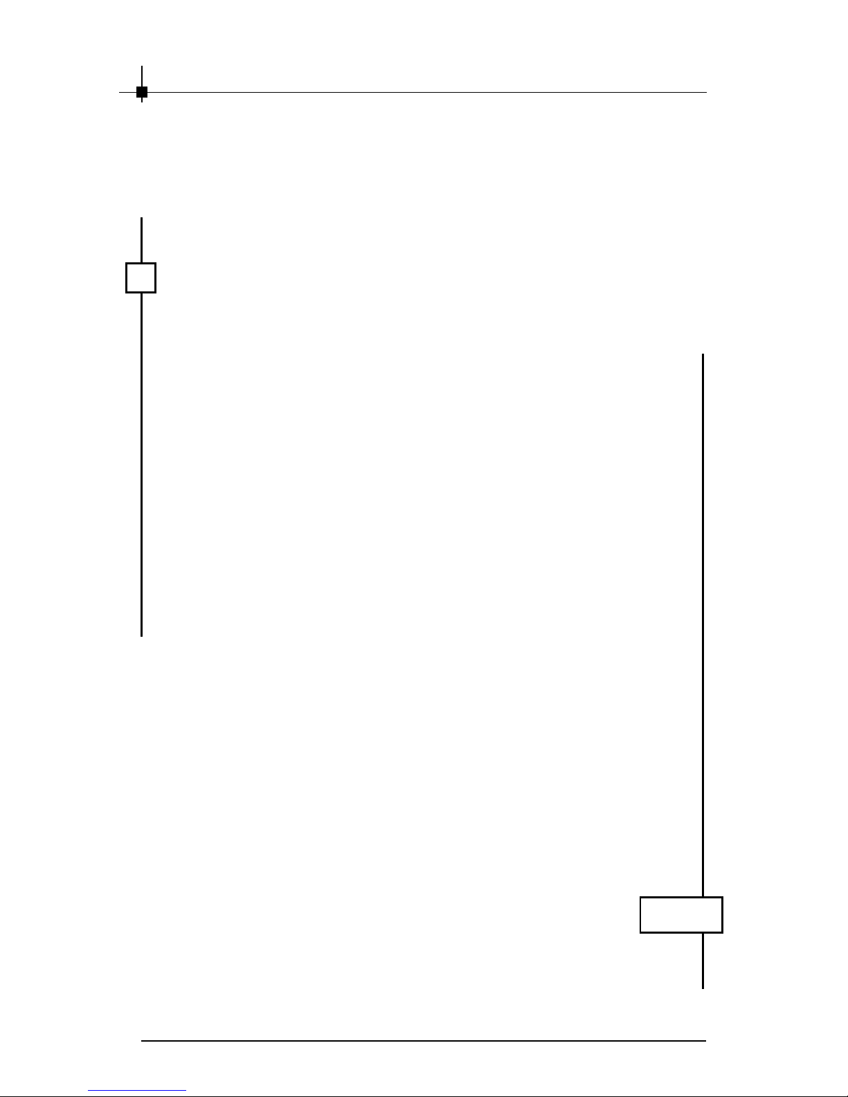
Computer Intel® Pentium II/III/4 proces sor,
Intel® Celeron pro cessor, or
compatible system
Expansion Slot AGP slot
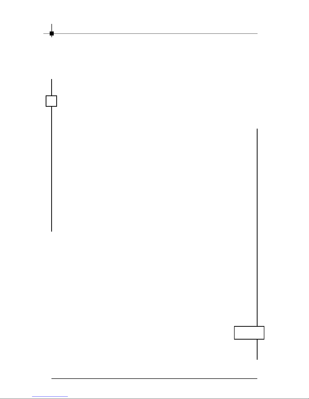
Monitor VGA support, minimum 640 x 480
resolu tion
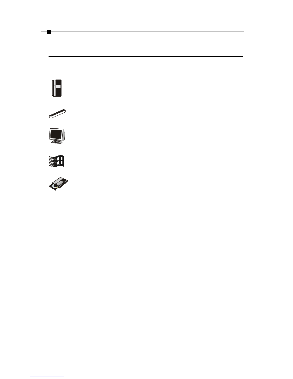
Operating System Windows® 2000, X P
CD-ROM Drive Double Spe ed or Higher
Page 13

Introduction
2-3
Features & Specifications
NX6800 Series
§ Supers calar GPU architec ture
§ NVIDIA® CineFX™ 3.0 engine
§ On-c hip Video processor delivers unmatched video performance and
features.
§ High-speed GDDR3/ DDR memory interface
§ 256-bit memory interface with advanced memory control
§ NVID IA® UltraShadow™ II technology enhances the performance of
bleeding-edge games that feature complex scenes with multiple light
sources and objects . Second-generation technology delivers more
than 4x the shadow proces sing power over the prev ious generation.
§ NVIDIA® High-Precision Dynamic-Range (HPDR) technology
§ 128-bit studio-precision c omputation prevents image defects due to
low precis ion and ensures the best image quality for even the most
demanding applic ations.
§ NVIDIA® Intellis ample™ 3.0 technology
§ Full MPEG Support
§ Advanced adaptive de-interlacing
§ Video scaling and filtering
§ Integrated TV encoder
§ NVID IA® ForceWare™ Unified Driver Architecture (UDA)
§ DirectX 9.0 and OpenGL 1.5 Optimizations and Support
§ NVIDIA® Digital Vibrance Control™ (DVC) 3.0
§ Dual-link DVI support
§ Over 220m transistors (Ultra series only)
§ Full support of AGP 8X including Fas t Writes and sideband address-
ing
§ Support for the industry’ s fastest GDDR3/ DDR memory
§ 256-bit adv anced memory interface
§ 0.13 micron process technology
§ Advanced thermal management and thermal monitoring
§ 40 mmx40 mm, BGA flip-chip package (Ultra series only)
§ Operating Sys tems Support Windows® XP / 2000
§ Power supply of 350 (and up) watt is highly recommended for
system stability
2.2 Card List
Page 14

Chapter 2
2-4
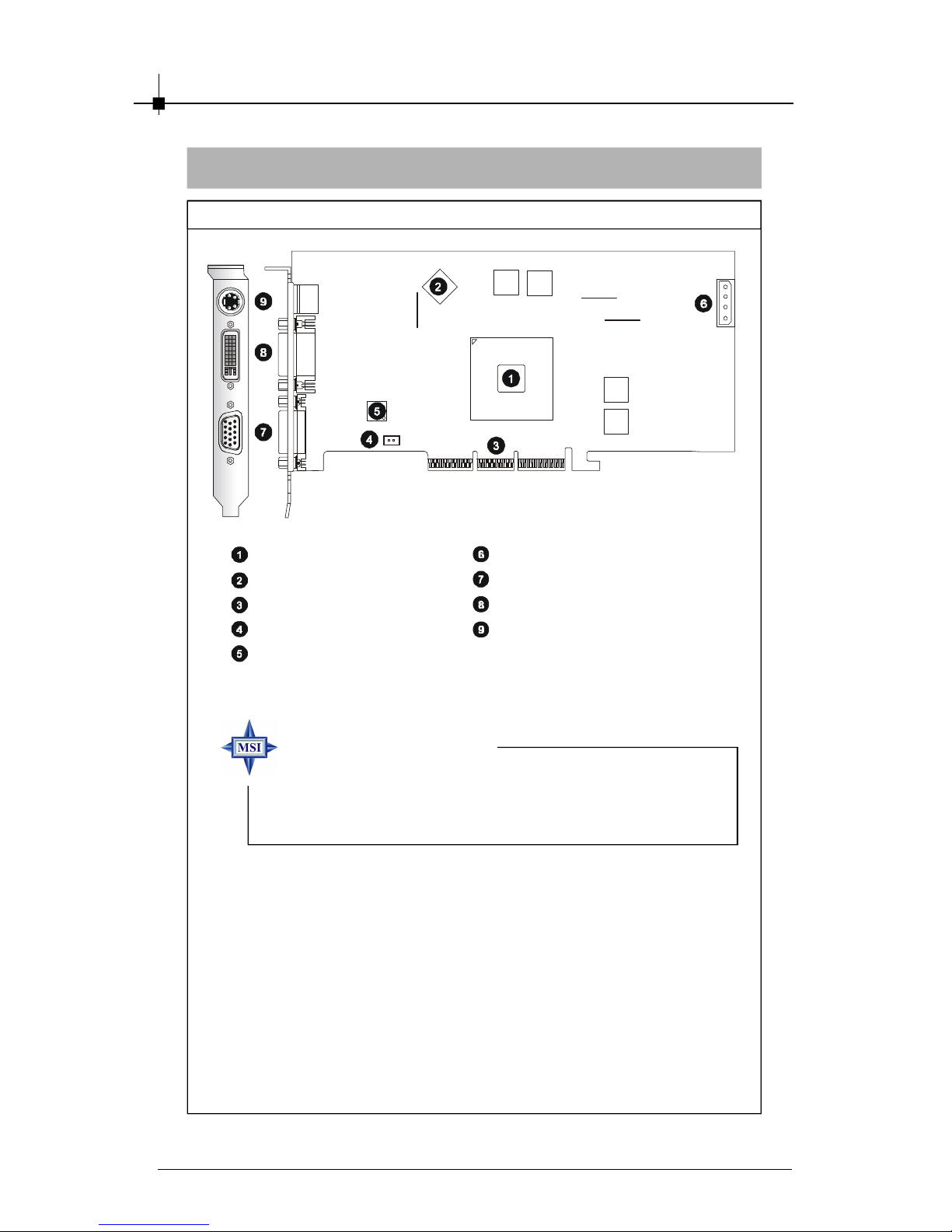
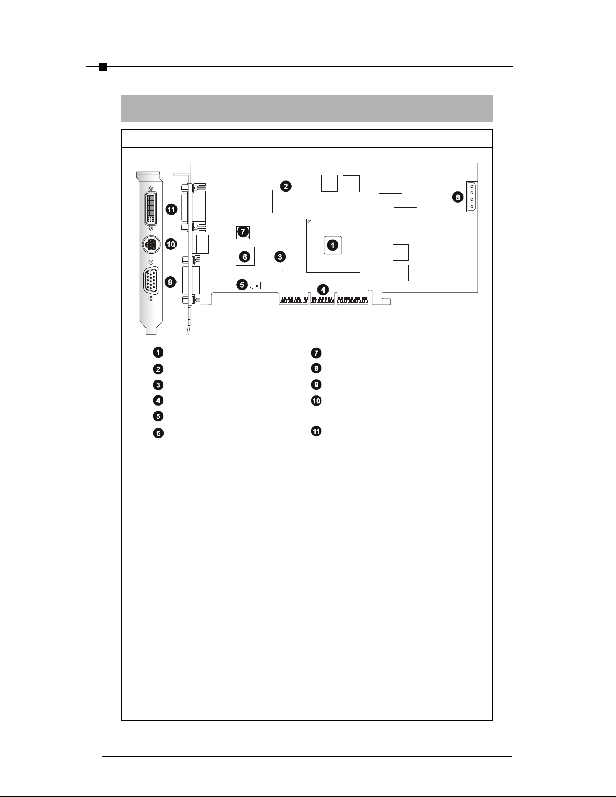
NX6800Ultra-T2D256
Layout
nVIDIA GeForce NX GPU
256MB DDR3 RAM
AGP Interfac e
Fan Connector
DVI Chip
Power Connector
Power Connector
DVI-I Connector
DVI-I Connector
TV_Out Connec tor (S)
Page 15
Introduction
2-5
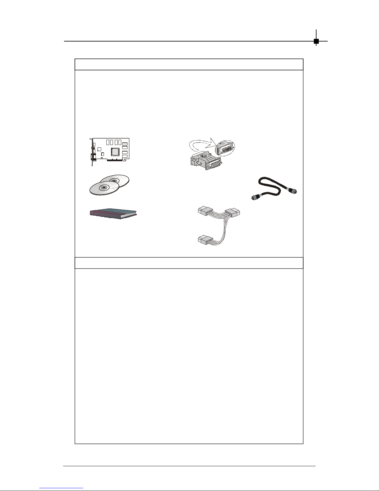
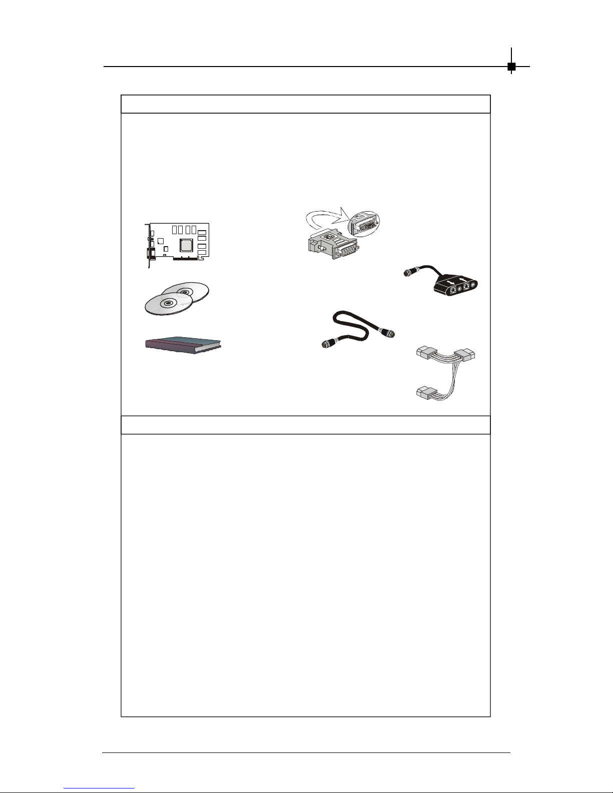
Package Contents
Unpack the package and inspect all the items carefully. If any item contained is damaged or missing, please contact your local dealer as soon as
possible. Also, keep the box and packing materials in c ase you need to
ship the unit in the future.
Your VGA card package should contain the following items :
VGA Card
Software
Pack CDs
User’ s Manual
Reference
2. INTRODUCTION ............................................................................. 2-1
3. HARDWARE INSTALLATION ......................................................... 3-1
3.1 Card Installation ...................................................................... 3-2
3.2 D-Sub Port (DB 15-Pin) ..........................................................3-9
3.3 Digital Panel Connector (DVI-I) ........................................... 3-10
3.5 TV_Out Connector (S) .......................................................... 3-11
4. SOFTWARE INSTALLATION .......................................................... 4-1
5. MSI LIVE UPDATE 3 ........................................................................ 5-1
5.1 Installing MSI Live Update 3 with MSI Live Monitor .............. 5-2
5.2 Using the MSI Live Update 3 ...................................................5- 3
5.3 Live VGA Drive Update ........................................................... 5-4
5.4 Live VGA BIOS Update ........................................................... 5-8
5.5 Live Utility ...............................................................................5-14
5.6 How to Use the MSI Live Monitor ......................................... 5-15
5.7 Contact Us ............................................................................. 5-22
6. TROUBLESHOOTING .................................................................... 6-1
DVI-I / VGA
Adapter
Power Cord x 2
TV-Out S-S
Connecting Cable
Page 16

Chapter 2
2-6
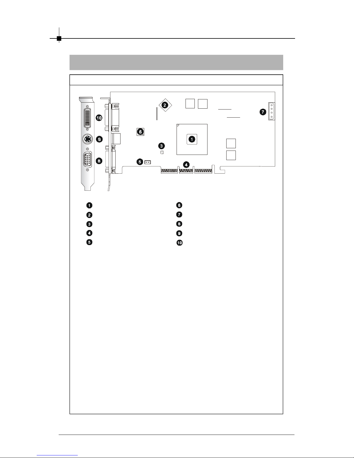
NX6800GT-TD256
Layout
nVIDIA GeForce NX GPU
256MB DDR3 RAM
AGP Interfac e
Fan Connector
DVI Chip
Power Connector
D-Sub Port (DB 15-Pin)
TV_Out Connec tor (S)
DVI-I Connector
MSI reminds you...
Note that the VGA card shown above may vary from the
actual card. For further information, p leas e visit MS I
website at http://www.msi.com.tw
Page 17

Introduction
2-7
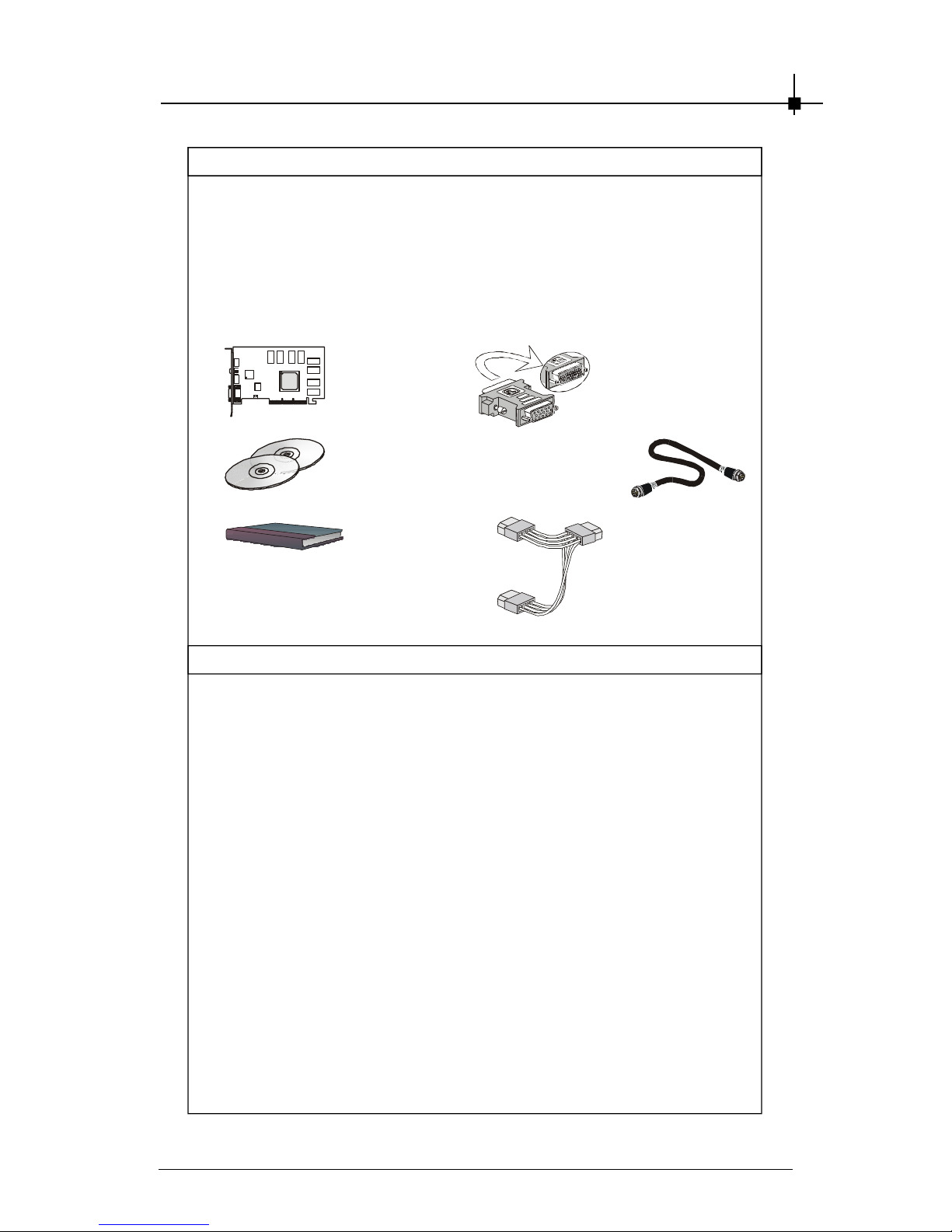
Package Contents
Unpack the package and inspect all the items carefully. If any item contained is damaged or missing, please contact your local dealer as soon as
possible. Also, keep the box and packing materials in c ase you need to
ship the unit in the future.
Your VGA card package should contain the following items :
VGA Card
Software
Pack CDs
User’ s Manual
Reference
2. INTRODUCTION ............................................................................. 2-1
3. HARDWARE INSTALLATION ......................................................... 3-1
3.1 Card Installation ...................................................................... 3-2
3.2 D-Sub Port (DB 15-Pin) ..........................................................3-9
3.3 Digital Panel Connector (DVI-I) ........................................... 3-10
3.5 TV_Out Connector (S) .......................................................... 3-11
4. SOFTWARE INSTALLATION .......................................................... 4-1
5. MSI LIVE UPDATE 3 ........................................................................ 5-1
5.1 Installing MSI Live Update 3 with MSI Live Monitor .............. 5-2
5.2 Using the MSI Live Update 3 ...................................................5- 3
5.3 Live VGA Drive Update ........................................................... 5-4
5.4 Live VGA BIOS Update ........................................................... 5-8
5.5 Live Utility ...............................................................................5-14
5.6 How to Use the MSI Live Monitor ......................................... 5-15
5.7 Contact Us ............................................................................. 5-22
6. TROUBLESHOOTING .................................................................... 6-1
DVI-I / VGA
Adapter
Power Cord x 1
TV-Out S-S
Connecting Cable
Page 18
Chapter 2
2-8
NX6800LE-TD256/TD128
Layout
nVIDIA GeForce NX GPU
256MB/128MB DDR RAM
AGP Interfac e
Fan Connector
DVI Chip
Power Connector
D-Sub Port (DB 15-Pin)
DVI-I Connector
TV_Out Connec tor (S)
MSI reminds you...
Note that the VGA card shown above may vary from the
actual card. For further information, p leas e visit MS I
website at http://www.msi.com.tw
Page 19
Introduction
2-9
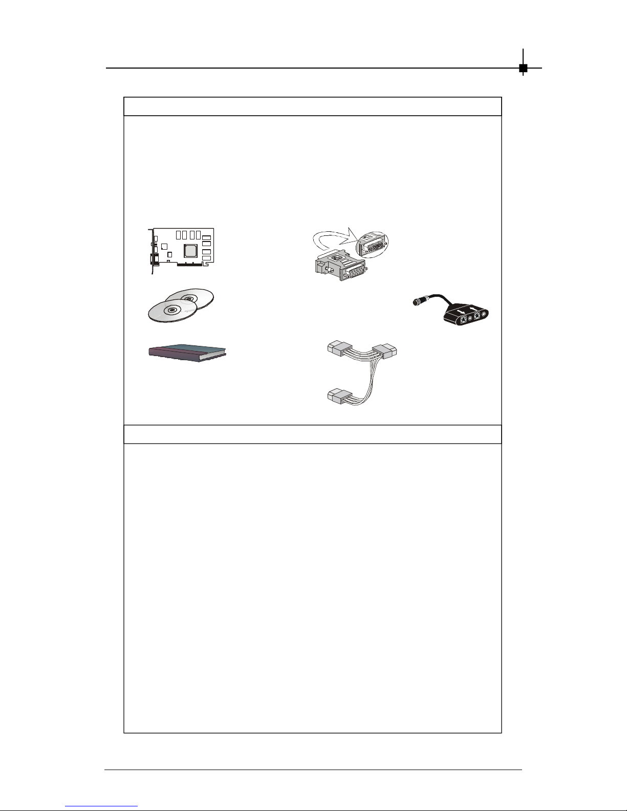
Package Contents
Unpack the package and inspect all the items carefully. If any item contained is damaged or missing, please contact your local dealer as soon as
possible. Also, keep the box and packing materials in c ase you need to
ship the unit in the future.
Your VGA card package should contain the following items :
VGA Card
Software
Pack CDs
User’ s Manual
Reference
2. INTRODUCTION ............................................................................. 2-1
3. HARDWARE INSTALLATION ......................................................... 3-1
3.1 Card Installation ...................................................................... 3-2
3.2 D-Sub Port (DB 15-Pin) ..........................................................3-9
3.3 Digital Panel Connector (DVI-I) ........................................... 3-10
3.5 TV_Out Connector (S) .......................................................... 3-11
4. SOFTWARE INSTALLATION .......................................................... 4-1
5. MSI LIVE UPDATE 3 ........................................................................ 5-1
5.1 Installing MSI Live Update 3 with MSI Live Monitor .............. 5-2
5.2 Using the MSI Live Update 3 ...................................................5- 3
5.3 Live VGA Drive Update ........................................................... 5-4
5.4 Live VGA BIOS Update ........................................................... 5-8
5.5 Live Utility ...............................................................................5-14
5.6 How to Use the MSI Live Monitor ......................................... 5-15
5.7 Contact Us ............................................................................. 5-22
6. TROUBLESHOOTING .................................................................... 6-1
DVI-I / VGA
Adapter
Power Cord x 1
TV-Out S-S
Connecting Cable
Page 20

Chapter 2
2-10
NX6800-TD256/TD128
Layout
nVIDIA GeForce NX GPU
256MB/128MB DDR RAM
AGP Interfac e
Fan Connector
DVI Chip
Power Connector
D-Sub Port (DB 15-Pin)
DVI-I Connector
TV_Out Connec tor (S)
MSI reminds you...
Note that the VGA card shown above may vary from the
actual card. For further information, p leas e visit MS I
website at http://www.msi.com.tw
Page 21

Introduction
2-11
Package Contents
Unpack the package and inspect all the items carefully. If any item contained is damaged or missing, please contact your local dealer as soon as
possible. Also, keep the box and packing materials in c ase you need to
ship the unit in the future.
Your VGA card package should contain the following items :
VGA Card
Software
Pack CDs
User’ s Manual
Reference
2. INTRODUCTION ............................................................................. 2-1
3. HARDWARE INSTALLATION ......................................................... 3-1
3.1 Card Installation ...................................................................... 3-2
3.2 D-Sub Port (DB 15-Pin) ..........................................................3-9
3.3 Digital Panel Connector (DVI-I) ........................................... 3-10
3.5 TV_Out Connector (S) .......................................................... 3-11
4. SOFTWARE INSTALLATION .......................................................... 4-1
5. MSI LIVE UPDATE 3 ........................................................................ 5-1
5.1 Installing MSI Live Update 3 with MSI Live Monitor .............. 5-2
5.2 Using the MSI Live Update 3 ...................................................5- 3
5.3 Live VGA Drive Update ........................................................... 5-4
5.4 Live VGA BIOS Update ........................................................... 5-8
5.5 Live Utility ...............................................................................5-14
5.6 How to Use the MSI Live Monitor ......................................... 5-15
5.7 Contact Us ............................................................................. 5-22
6. TROUBLESHOOTING .................................................................... 6-1
DVI-I / VGA
Adapter
Page 22

Chapter 2
2-12
NX6800-VTD256/VTD128
Layout
nVIDIA GeForce NX GPU
256MB/128MB DDR RAM
AGP Interfac e
Fan Connector
DVI Chip
Power Connector
D-Sub Port (DB 15-Pin)
DVI-I Connector
TV_Out / Video_In
Connector (S&C)
MSI reminds you...
Note that the VGA card shown above may vary from the
actual card. For further information, p leas e visit MS I
website at http://www.msi.com.tw
Page 23
Introduction
2-13
Package Contents
Unpack the package and inspect all the items carefully. If any item contained is damaged or missing, please contact your local dealer as soon as
possible. Also, keep the box and packing materials in c ase you need to
ship the unit in the future.
Your VGA card package should contain the following items :
VGA Card
So ftware
Pack CDs
User’ s Manual
Re f e r e nc e
2. I NT R OD UC T IO N ....................................................................................... 2 - 1
3. HAR D W A RE I N STA LL AT I ON ................................................................ 3- 1
3. 1 Car d Installation ............................................................................... 3 - 2
3. 2 D-S ub Po rt (D B 15 - Pi n ) ................................................................. 3 - 9
3. 3 Dig ita l Pan el Co nne ct o r (D V I- I ) ................................................ 3 - 1 0
3. 9 TV_ O u t / Vi deo_In Con n ec t or (S & C ) ...................................... 3- 14
4. S O FT W A RE I NS TA L LAT IO N ................................................................. 4 - 1
5. MSI LI VE UPDAT E 3 .................................................................................. 5- 1
5. 1 Inst a l ling MS I Live Up date 3 with MSI Live Monit o r ................ 5 - 2
5. 2 Us i ng the MSI Live Updat e 3 ......................................................... 5 - 3
5. 3 Li ve VGA Dr i v e Up d ate ................................................................... 5 - 4
5. 4 Li ve VGA BIOS Update ................................................................... 5 - 8
5. 5 Live Ut i lity ........................................................................................ 5 - 1 4
5. 6 How to Use the MSI Li ve Monito r .............................................. 5- 15
5. 7 Con t act Us ...................................................................................... 5 - 2 2
6. T RO U BL ES HO O T I NG ............................................................................. 6 - 1
DVI- I / VGA
Adapter
Power Cor d x 1
TV-Out / Video_In
1-to-4 Connecting
Cable
Page 24

C h ap t e r 2
2-14
Featu re s & Sp eci fi ca ti o ns
FX5950Ultra Series
§ 256-bit memory interface with adv anced memory control
§ NVIDIA UltraShadow™ technology
§ NVIDIA
®
CineFX™ 2.0 engine
§ Advanced pixel s haders
§ 128-bit studio- precis ion computation
§ NVIDIA
®
Intellisample™ high-r esolution c ompres sion
technology (HCT )
§ NVIDIA
®
ForceWare™ unified software environment (USE)
- NVIDIA® Unified Driver Architecture (UDA)
- Compatibility, Stability, Reliability
- NVIDIA® nView™ multi-display tec hnology
- Continual performance and feature updates over life of the pr oduct
§ NVIDIA Unified Driver Arc hitec ture (UDA)
§ Dir ectX 9.0 Optimiz ations and Support
§ OpenGL 1.5 O ptimizations and Support
§ NVIDIA
®
nView™ multi-display technology
§ NVIDIA
®
Digital Vibrance Contr ol™ (DVC) 3.0
§ AGP 8X
§ DVI Support
§ Integrated TV encoder
§ Integr ated full hardware MPEG-2 dec oder
§ 64-phase video scaler
§ Architected for Cg
§ Blazing speeds and ultr a-high resolutions for nex t-genera
tion games
- 256- bit memory bus for increas ed memory bandwidth
- Support for up to 256MB memory size
- .13u micron for faster clock rates
- Engineered for today’ s advanced games
§ 0.13-mic ron process technology for higher lev els of integration and
higher operating c lock speeds.
§ Engine clock speed: 250MH z
§ Full precis ion DX9 performance: 4x
Page 25
Introduction
2-15
Featu re s & Sp eci fi ca ti o ns
§ Effectiv e Memory Bandwidth: 6.4GB/s (This value is for reference
only , depending ont he type of memory implemented)
§ Bandwidth compression ratio: 6:1
§ Peak Pixel Fill Rate: 6+ GB/s
§ Rendering Pipeline: 4
§ G eometry Pipeline: 2
§ Peak vertex thr oughput Mvertices/sec: 750+
§ Dual RAMDACs : 400MHz
§ Operating Systems Support Windows
®
XP / 2000
§ Power supply of 350 (and up) watt is highly rec ommended for
system stability
Page 26

C h ap t e r 2
2-16
FX5950Ultra-VTD 256
La y ou t
DVI Chip
Power Connector
D-Sub Port (DB 15- Pin)
TV_Out / Video_In
Connector (S&C)
DVI- I Connector
nVIDIA GeFor ce FX GPU
256MB DDR RAM
Flash-BIOS
AGP Interface
Fan Connector
Video Decoder
Page 27

Introduction
2-17
Pa ck age Con t en ts
Unpack the pac kage and ins pect all the items car efully. If any item contained is damaged or missing, pleas e contact y our local dealer as soon as
poss ible. Also, keep the box and packing mater ials in case y ou need to
ship the unit in the future.
Your VG A card pac kage should contain the following items:
VGA Card
So ftware
Pack CDs
User’ s Manual
Re f e r e nc e
2. I NT R OD UC T IO N ....................................................................................... 2 - 1
3. HAR D W A RE I N STA LL AT I ON ................................................................ 3- 1
3. 1 Car d Installation ............................................................................... 3 - 2
3. 2 D-S ub Po rt (D B 15 - Pi n ) ................................................................. 3 - 9
3. 3 Dig ita l Pan el Co nne ct o r (D V I- I ) ................................................ 3 - 1 0
3. 9 TV_ O u t / Vi deo_In Con n ec t or (S & C ) ...................................... 3- 14
4. S O FT W A RE I NS TA L LAT IO N ................................................................. 4 - 1
5. MSI LI VE UPDAT E 3 .................................................................................. 5- 1
5. 1 Inst a l ling MS I Live Up date 3 with MSI Live Monit o r ................ 5 - 2
5. 2 Us i ng the MSI Live Updat e 3 ......................................................... 5 - 3
5. 3 Li ve VGA Dr i v e Up d ate ................................................................... 5 - 4
5. 4 Li ve VGA BIOS Update ................................................................... 5 - 8
5. 5 Live Ut i lity ........................................................................................ 5 - 1 4
5. 6 How to Use the MSI Li ve Monito r .............................................. 5- 15
5. 7 Con t act Us ...................................................................................... 5 - 2 2
6. T RO U BL ES HO O T I NG ............................................................................. 6 - 1
DVI- I / VGA
Adapter
TV-Out / Video_In
1-to-4 Connecting
Cable
Power Cord
TV-Out S-S
Connecting Cable
Page 28
C h ap t e r 2
2-18
FX5950Ultra-VTD 128
La y ou t
DVI Chip
Power Connector
D-Sub Port (DB 15- Pin)
TV_Out / Video_In
Connector (S&C)
DVI- I Connector
nVIDIA GeFor ce FX GPU
128MB DDR RAM
Flash-BIOS
AGP Interface
Fan Connector
Video Decoder
Page 29
Introduction
2-19
Pa ck age Con t en ts
Unpack the pac kage and ins pect all the items car efully. If any item contained is damaged or missing, pleas e contact y our local dealer as soon as
poss ible. Also, keep the box and packing mater ials in case y ou need to
ship the unit in the future.
Your VG A card pac kage should contain the following items:
VGA Card
So ftware
Pack CDs
User’ s Manual
Re f e r e nc e
2. I NT R OD UC T IO N ....................................................................................... 2 - 1
3. HAR D W A RE I N STA LL AT I ON ................................................................ 3- 1
3. 1 Car d Installation ............................................................................... 3 - 2
3. 2 D-S ub Po rt (D B 15 - Pi n ) ................................................................. 3 - 9
3. 3 Dig ita l Pan el Co nne ct o r (D V I- I ) ................................................ 3 - 1 0
3. 9 TV_ O u t / Vi deo_In Con n ec t or (S & C ) ...................................... 3- 14
4. S O FT W A RE I NS TA L LAT IO N ................................................................. 4 - 1
5. MSI LI VE UPDAT E 3 .................................................................................. 5- 1
5. 1 Inst a l ling MS I Live Up date 3 with MSI Live Monit o r ................ 5 - 2
5. 2 Us i ng the MSI Live Updat e 3 ......................................................... 5 - 3
5. 3 Li ve VGA Dr i v e Up d ate ................................................................... 5 - 4
5. 4 Li ve VGA BIOS Update ................................................................... 5 - 8
5. 5 Live Ut i lity ........................................................................................ 5 - 1 4
5. 6 How to Use the MSI Li ve Monito r .............................................. 5- 15
5. 7 Con t act Us ...................................................................................... 5 - 2 2
6. T RO U BL ES HO O T I NG ............................................................................. 6 - 1
DVI- I / VGA
Adapter
TV-Out / Video_In
1-to-4 Connecting
Cable
Power Cord
TV-Out S-S
Connecting Cable
Page 30
C h ap t e r 2
2-20
FX5950Ultra-TD25 6
La y ou t
nVIDIA GeFor ce FX GPU
256MB DDR RAM
Flash-BIOS
AGP Interface
Fan Connector
DVI Chip
Power Connector
D-Sub Port (DB 15- Pin)
TV_Out Connec tor (S)
DVI- I Connector
Page 31

Introduction
2-21
Pa ck age Con t en ts
Unpack the pac kage and ins pect all the items car efully. If any item contained is damaged or missing, pleas e contact y our local dealer as soon as
poss ible. Also, keep the box and packing mater ials in case y ou need to
ship the unit in the future.
Your VG A card pac kage should contain the following items:
VGA Card
Software
Pack CDs
User’ s Manual
Reference
2. INTRODUCTION ............................................................................. 2-1
3. HARDWARE INSTALLATION ......................................................... 3-1
3.1 Card Installation ...................................................................... 3-2
3.2 D-Sub Port (DB 15-Pin) ..........................................................3-9
3.3 Digital Panel Connector (DVI-I) ........................................... 3-10
3.5 TV_Out Connector (S) .......................................................... 3-11
4. SOFTWARE INSTALLATION .......................................................... 4-1
5. MSI LIVE UPDATE 3 ........................................................................ 5-1
5.1 Installing MSI Live Update 3 with MSI Live Monitor .............. 5-2
5.2 Using the MSI Live Update 3 ...................................................5- 3
5.3 Live VGA Drive Update ........................................................... 5-4
5.4 Live VGA BIOS Update ........................................................... 5-8
5.5 Live Utility ...............................................................................5-14
5.6 How to Use the MSI Live Monitor ......................................... 5-15
5.7 Contact Us ............................................................................. 5-22
6. TROUBLESHOOTING .................................................................... 6-1
DVI-I / VGA
Adapter
Power Cord
TV-Out S-C
Connecting Cable
Page 32

Chapter 2
2-22
FX5950Ultra-TD128
Layout
nVIDIA GeForce FX GPU
128MB DDR RAM
Flash-BIOS
AGP Interfac e
Fan Connector
DVI Chip
Power Connector
D-Sub Port (DB 15-Pin)
TV_Out Connec tor (S)
DVI-I Connector
Page 33

Introduction
2-23
Package Contents
Unpack the pac kage and ins pect all the items car efully. If any item contained is damaged or missing, pleas e contact y our local dealer as soon as
poss ible. Also, keep the box and packing mater ials in case y ou need to
ship the unit in the future.
Your VG A card pac kage should contain the following items:
VGA Card
So ftware
Pack CDs
User’ s Manual
Re f e r e nc e
2. I NT R OD UC T IO N ....................................................................................... 2 - 1
3. HAR D W A RE I N STA LL AT I ON ................................................................ 3- 1
3. 1 Car d Installation ............................................................................... 3 - 2
3. 2 D-S ub Po rt (D B 15 - Pi n ) ................................................................. 3 - 9
3. 3 Dig ita l Pan el Co nne ct o r (D V I- I ) ................................................ 3 - 1 0
3. 5 TV_O ut C on n e c t o r (S) .................................................................. 3- 11
4. S O FT W A RE I NS TA L LAT IO N ................................................................. 4 - 1
5. MSI LI VE UPDAT E 3 .................................................................................. 5- 1
5. 1 Inst a l ling MS I Live Up date 3 with MSI Live Monit o r ................ 5 - 2
5. 2 Us i ng the MSI Live Updat e 3 ......................................................... 5 - 3
5. 3 Li ve VGA Dr i v e Up d ate ................................................................... 5 - 4
5. 4 Li ve VGA BIOS Update ................................................................... 5 - 8
5. 5 Live Ut i lity ........................................................................................ 5 - 1 4
5. 6 How to Use the MSI Li ve Monito r .............................................. 5- 15
5. 7 Con t act Us ...................................................................................... 5 - 2 2
6. T RO U BL ES HO O T I NG ............................................................................. 6 - 1
DVI- I / VGA
Adapter
Power Cord
TV-Out S-C
Connecting Cable
Page 34

C h ap t e r 2
2-24
2 5 6- BI T A D VA NC ED ME MO R Y I N T ER F A CE
§ Wider memory data path with next generation contr oller tec hnol-
ogy for superior perfor mance and throughput.
NV I D I A C IN E FX 2.0 E NG I NE
§ Adv anced pixel shader s deliver 2x the floating-point shader pixel
performance of previous generations.
§ Support for Micros oft
®
DirectX® 9.0 (DX9) pixel shader
2.0 +.
§ Support for DX9 v ertex shader 2.0+.
§ Long pixel progr ams up to 1,024 instructions.
§ Long v ertex programs up to 256 static instruc tions with up to 65,
536 instructions executed.
§ Dynamic, conditional exec ution and flow c ontrol.
§ Arc hitected for Cg and Mic ros oft HLSL for maximum c ompatibility
for nextgeneration content.
§ 128-bit, studio-quality, floating- point precis ion computation through
the entire render ing pipeline.
§ Native hardware suppor t for 32 bpp, 64 bpp and 128 bpp
rendering modes.
§ Up to 12 pixel s hader operations/c lock.
§ Up to 16 textur es per rendering pas s.
§ Support for sRG B tex ture format for gamma textures.
§ Dir ectX and S3TC texture c ompression.
§ Optimized for 32-, 24-, 16-, 15- and 8- bpp mode.
§ True-color, 64x64 hardware cursor alpha.
§ Multibuffer ing (double, triple or quad) for smooth animation and
video playback.
I N TE LL IS AM PL E H C T P E R FO RM AN CE T E C H N O LO G Y
§ Inc reased v isual quality at higher res olutions through advances in
compression, anisotropic filtering, and antialiasing technology.
§ Blistering-fas t antialiasing and compr ession performance
§ Support for advanc ed lossles s compression algorithms for both
color, texture, and z data at even higher r esolutions and frame
rates .
§ Fas t z-clear.
U LT RA S HA D OW T E CH N OL O G Y
§ Accelerates shadow volumes for nextgeneration games.
§ Accurately maintains shadows while discarding non-useful
information
AD VAN CE D DI S P LAY PI P EL I N E W IT H FU L L NV I DI A N V IE W
TM
C A PA B IL IT IE S
§ DVD and HDTV-ready MPEG-2 decoding up to 1920x1080i
resolutions.
Featu re s & Sp eci fi ca ti o ns
FX5900Ultra Series
Page 35

Introduction
2-25
§ Integrated NTSC/PAL T V encoder suppor ting resolutions up to
1024x768 without the need for panning with built-in Mac rovision
copy protection.
§ Dual, integrated 400MHz RAMDACs for display resolutions up to
and including 2048x1536@85Hz
§ Dual DV0 ports for interfacing to external TMDS transmitters .
§ Internal T V support.
§ Dual internal TMDS enc oders (one single and one Dual link) able to
drive nex tgener ation flat panel dis plays with resolutions greater
than 1600x1200.
§ VIP 1.1 interfac e support for Video In function.
§ Micr osoft Video Mixing Render er (VMR) support for multiple v ideo
windows with full video quality and features in each window.
NV I D IA D IG ITA L V I BR AN CE C O NTR O LTM (D V C ) 3 . 0
§ DVC image sharpening controls.
§ DVC color controls. multiple video windows with full v ideo quality
and features in each window.
A D VA N C ED T EC H N OL OG Y
§ AGP 8X including Fast Writes and sideband addr ess ing.
§ 0.13-micron proc ess technology for higher lev els of integr ation
and higher oper ating clock speeds .
§ Advanced thermal management and thermal monitoring.
§ 40 mmx40 mm, BGA 1309 flip-chip pac kage.
B R OA D O P E R A T I N G S Y S T E M S U PP O RT
§ Windows
®
XP / 2000
A P I S U P P O R T
§ Comprehensive Microsoft DirectX 9.0 (and lower) support.
§ OpenGL 1.4 (and lower) support
C O M PA T I B I L I T Y
§ NVIDIA
®
Unified Driver Arc hitecture (UDA) .
§ Fully c ompliant professional O penG L 1.4 API with NVIDIA
extensions.
§ Complete Linux Xfree86 driv ers.
P O WE R S U PP LY
§ Power supply of 350 (and up) watt is highly rec ommended for
system stability
Featu re s & Sp eci fi ca ti o ns
Page 36

C h ap t e r 2
2-26
FX5900Ultra-VTDR256
La y ou t
Video Decoder
Power Connector
D-Sub Port (DB 15- Pin)
TV_Out / Video_In Connector
(S&C) + Remote Receiver
DVI- I Connector
nVIDIA GeFor ce FX GPU
256MB DDR RAM
Flash-BIOS
AGP Interface
Fan Connector
Page 37

Introduction
2-27
Pa ck age Con t en ts
Unpack the pac kage and ins pect all the items car efully. If any item contained is damaged or missing, pleas e contact y our local dealer as soon as
poss ible. Also, keep the box and packing mater ials in case y ou need to
ship the unit in the future.
Your VG A card pac kage should contain the following items:
VGA Card
So ftware
Pack CDs
User’ s Manual
Re f e r e nc e
2. I NT R OD UC T IO N ....................................................................................... 2 - 1
3. HAR D W A RE I N STA LL AT I ON ................................................................ 3- 1
3. 1 Car d Installation ............................................................................... 3 - 2
3. 2 D-S ub Po rt (D B 15 - Pi n ) ................................................................. 3 - 9
3. 3 Dig ita l Pan el Co nne ct o r (D V I- I ) ................................................ 3 - 1 0
3. 9 TV_ O u t / Vi deo_In Con n ec t or (S & C ) ...................................... 3- 14
4. S O FT W A RE I NS TA L LAT IO N ................................................................. 4 - 1
5. MSI LI VE UPDAT E 3 .................................................................................. 5- 1
5. 1 Inst a l ling MS I Live Up date 3 with MSI Live Monit o r ................ 5 - 2
5. 2 Us i ng the MSI Live Updat e 3 ......................................................... 5 - 3
5. 3 Li ve VGA Dr i v e Up d ate ................................................................... 5 - 4
5. 4 Li ve VGA BIOS Update ................................................................... 5 - 8
5. 5 Live Ut i lity ........................................................................................ 5 - 1 4
5. 6 How to Use the MSI Li ve Monito r .............................................. 5- 15
5. 7 Con t act Us ...................................................................................... 5 - 2 2
6. T RO U BL ES HO O T I NG ............................................................................. 6 - 1
DVI-I / VGA Adapter
Po wer
Cord
TV_O ut / Video_In 1to-4 Connecting Cable
+ Remote Receiver
Remote
Controller
TV-Out S-S Connecting Cable
Page 38

C h ap t e r 2
2-28
FX5900Ultra-TDR256
La y ou t
Power Connector
D-Sub Port (DB 15- Pin)
TV_O ut Connec tor (S&C) +
Remote Receiver
DVI- I Connector
nVIDIA GeFor ce FX GPU
256MB DDR RAM
Flash-BIOS
AGP Interface
Fan Connector
Page 39

Introduction
2-29
Pa ck age Con t en ts
Unpack the pac kage and ins pect all the items car efully. If any item contained is damaged or missing, pleas e contact y our local dealer as soon as
poss ible. Also, keep the box and packing mater ials in case y ou need to
ship the unit in the future.
Your VG A card pac kage should contain the following items:
VGA Card
So ftware
Pack CDs
User’ s Manual
Re f e r e nc e
2. I NT R OD UC T IO N ....................................................................................... 2 - 1
3. HAR D W A RE I N STA LL AT I ON ................................................................ 3- 1
3. 1 Car d Installation ............................................................................... 3 - 2
3. 2 D-S ub Po rt (D B 15 - Pi n ) ................................................................. 3 - 9
3. 3 Dig ita l Pan el Co nne ct o r (D V I- I ) ................................................ 3 - 1 0
3. 9 TV_ O u t / Vi deo_In Con n ec t or (S & C ) ...................................... 3- 14
4. S O FT W A RE I NS TA L LAT IO N ................................................................. 4 - 1
5. MSI LI VE UPDAT E 3 .................................................................................. 5- 1
5. 1 Inst a l ling MS I Live Up date 3 with MSI Live Monit o r ................ 5 - 2
5. 2 Us i ng the MSI Live Updat e 3 ......................................................... 5 - 3
5. 3 Li ve VGA Dr i v e Up d ate ................................................................... 5 - 4
5. 4 Li ve VGA BIOS Update ................................................................... 5 - 8
5. 5 Live Ut i lity ........................................................................................ 5 - 1 4
5. 6 How to Use the MSI Li ve Monito r .............................................. 5- 15
5. 7 Con t act Us ...................................................................................... 5 - 2 2
6. T RO U BL ES HO O T I NG ............................................................................. 6 - 1
9-SC TV-Out
Connecting Cable +
Remote Receiver
DVI-I / VGA Adapter
Power
Cord
Remote
Controller
TV-Out S-S Connecting Cable
Page 40

Chapter 2
2-30
FX5900Ultra-VTD256
Layout
Video Dec oder
Power Connector
D-Sub Port (DB 15-Pin)
TV_Out / Video_In
Connector (S&C)
DVI-I Connector
nVIDIA GeForce FX GPU
256MB DDR RAM
Flash-BIOS
AGP Interfac e
Fan Connector
Page 41

Introduction
2-31
Package Contents
Unpack the package and inspect all the items carefully. If any item contained is damaged or missing, please contact your local dealer as soon as
possible. Also, keep the box and packing materials in c ase you need to
ship the unit in the future.
Your VGA card package should contain the following items :
VGA Card
Software
Pack CDs
User’ s Manual
Reference
2. INTRODUCTION ............................................................................. 2-1
3. HARDWARE INSTALLATION ......................................................... 3-1
3.1 Card Installation ...................................................................... 3-2
3.2 D-Sub Port (DB 15-Pin) ..........................................................3-9
3.3 Digital Panel Connector (DVI-I) ........................................... 3-10
3.9 TV_Out / Video_In Connector (S&C) ...................................3-14
4. SOFTWARE INSTALLATION .......................................................... 4-1
5. MSI LIVE UPDATE 3 ........................................................................ 5-1
5.1 Installing MSI Live Update 3 with MSI Live Monitor .............. 5-2
5.2 Using the MSI Live Update 3 ...................................................5- 3
5.3 Live VGA Drive Update ........................................................... 5-4
5.4 Live VGA BIOS Update ........................................................... 5-8
5.5 Live Utility ...............................................................................5-14
5.6 How to Use the MSI Live Monitor ......................................... 5-15
5.7 Contact Us ............................................................................. 5-22
6. TROUBLESHOOTING .................................................................... 6-1
DVI-I / VGA
Adapter
TV-Out / Video_In
1-to-4 Connecting
Cable
Power Cord
TV-Out S-S
Connecting Cable
Page 42

Chapter 2
2-32
FX5900Ultra-TD256
Layout
nVIDIA GeForce FX GPU
256MB DDR RAM
Flash-BIOS
AGP Interfac e
Fan Connector
Power Connector
D-Sub Port (DB 15-Pin)
TV_Out Connec tor (S)
DVI-I Connector
Page 43

Introduction
2-33
Package Contents
Unpack the package and inspect all the items carefully. If any item contained is damaged or missing, please contact your local dealer as soon as
possible. Also, keep the box and packing materials in c ase you need to
ship the unit in the future.
Your VGA card package should contain the following items :
VGA Card
Software
Pack CDs
User’ s Manual
Reference
2. INTRODUCTION ............................................................................. 2-1
3. HARDWARE INSTALLATION ......................................................... 3-1
3.1 Card Installation ...................................................................... 3-2
3.2 D-Sub Port (DB 15-Pin) ..........................................................3-7
3.3 Digital Panel Connector (DVI-I) ............................................. 3-8
3.5 TV_Out Connector (S) ............................................................ 3-9
4. SOFTWARE INSTALLATION .......................................................... 4-1
5. MSI LIVE UPDATE 3 ........................................................................ 5-1
5.1 Installing MSI Live Update 3 with MSI Live Monitor .............. 5-2
5.2 Using the MSI Live Update 3 ...................................................5- 3
5.3 Live VGA Drive Update ........................................................... 5-4
5.4 Live VGA BIOS Update ........................................................... 5-8
5.5 Live Utility ...............................................................................5-14
5.6 How to Use the MSI Live Monitor ......................................... 5-15
5.7 Contact Us ............................................................................. 5-22
6. TROUBLESHOOTING .................................................................... 6-1
DVI-I / VGA
Adapter
Power Cord
Page 44

Chapter 2
2-34
256-BIT ADVANCED MEMORY INTERFACE
§ Wider memory data path with next generation controller technology for superior performance and throughput.
NVIDIA CINEFX 2.0 ENGINE
§ Advanced pixel shaders deliver 2x the floating-point shader pixel
performance of previous generations.
§ Support for Micros oft® DirectX® 9.0 (DX9) pixel shader
2.0 +.
§ Support for DX9 vertex shader 2.0+.
§ Long pixel programs up to 1,024 instructions .
§ Long vertex programs up to 256 static instructions with up to 65,
536 instructions executed.
§ Dynamic, c onditional execution and flow control.
§ Architected for Cg and Mic rosoft HLSL for maximum compatibility
for nextgeneration content.
§ 128-bit, studio-quality, floating-point precision computation through
the entire rendering pipeline.
§ Native hardware support for 32 bpp, 64 bpp and 128 bpp
rendering modes.
§ Up to 12 pixel shader operations/cloc k.
§ Up to 16 textures per rendering pass.
§ Support for sRGB texture format for gamma textures .
§ DirectX and S3TC texture compression.
§ Optimized for 32-, 24-, 16-, 15- and 8- bpp mode.
§ True-color, 64x 64 hardware cursor alpha.
§ Multibuffering (double, triple or quad) for smooth animation and
video playback.
INTELLISAMPLE HCT PERFORMAN CE TECHNOLOGY
§ Increased v isual quality at higher resolutions through advanc es in
compression, anisotropic filtering, and antialiasing technology .
§ Blistering-fast antialiasing and compress ion performance
§ Support for advanc ed los sless compression algorithms for both
color, tex ture, and z data at even higher resolutions and frame
rates.
§ Fast z-c lear.
ULTRASHADOW TECHNOLOGY
§ Accelerates shadow volumes for nextgeneration games.
§ Accurately maintains shadows w hile discarding non-useful
information
ADVANCED DISPLAY PIPELINE WITH FULL NVIDIA NVIEW
TM
CAPABILITIES
§ DVD and HDTV-ready MPEG-2 decoding up to 1920x1080i
resolutions.
Features & Specifications
FX5900 Series
Page 45

Introduction
2-35
Features & Specifications
§ Integrated NTSC/PAL TV encoder supporting resolutions up to
1024x768 without the need for panning with built-in Macrovis ion
copy protection.
§ Dual, integrated 400MHz RAMDACs for display resolutions up to
and including 2048x1536@85Hz
§ Dual DV0 ports for interfacing to external TMDS transmitters.
§ Internal TV support.
§ Dual internal TMDS encoders (one single and one Dual link) able
to drive nextgeneration flat panel dis plays with resolutions
greater than 1600x1200.
§ VIP 1.1 interface support for Video In function.
§ Microsoft Video Mixing Renderer (VMR) s upport for multiple v ideo
windows with full video quality and features in each window.
NVIDIA DIGITAL VIBRANCE CONTROLTM (DVC) 3.0
§ DVC image sharpening controls.
§ DVC color controls. multiple v ideo windows with full video quality
and features in each window.
ADVANCED TECHNOLOGY
§ AGP 8X including Fast Writes and sideband addressing.
§ 0.13-micron process technology for higher levels of integration
and higher operating clock speeds.
§ Advanced thermal management and thermal monitoring.
§ 40 mmx40 mm, BGA 1309 flip-chip pac kage.
BRO AD OPERATING SYSTEM SUPPORT
§ Windows® XP / 2000
API SUPPORT
§ Comprehensive Microsoft DirectX 9.0 (and lower) support.
§ OpenGL 1.4 (and lower) support
COMPATIBI LITY
§ NVIDIA Unified Driv er Arc hitecture (UDA).
§ Fully compliant professional OpenGL 1.4 API with NVIDIA
extensions.
§ Complete Linux Xfree86 drivers .
POWER SUPPLY
§ Power supply of 350 (and up) watt is highly recommended for
system stability
Page 46

Chapter 2
2-36
FX5900ZT-TD256/TD128
Layout
nVIDIA GeForce FX GPU
256MB/128MB DDR RAM
AGP Interfac e
Fan Connector
DVI Chip
Power Connector
D-Sub Port (DB 15-Pin)
TV_Out Connec tor (S)
DVI-I Connector
Page 47

Introduction
2-37
Package Contents
Unpack the package and inspect all the items carefully. If any item contained is damaged or missing, please contact your local dealer as soon as
possible. Also, keep the box and packing materials in c ase you need to
ship the unit in the future.
Your VGA card package should contain the following items :
VGA Card
Software
Pack CDs
User’ s Manual
Reference
2. INTRODUCTION ............................................................................. 2-1
3. HARDWARE INSTALLATION ......................................................... 3-1
3.1 Card Installation ...................................................................... 3-2
3.2 D-Sub Port (DB 15-Pin) ..........................................................3-7
3.3 Digital Panel Connector (DVI-I) ............................................. 3-8
3.5 TV_Out Connector (S) ............................................................ 3-9
4. SOFTWARE INSTALLATION .......................................................... 4-1
5. MSI LIVE UPDATE 3 ........................................................................ 5-1
5.1 Installing MSI Live Update 3 with MSI Live Monitor .............. 5-2
5.2 Using the MSI Live Update 3 ...................................................5- 3
5.3 Live VGA Drive Update ........................................................... 5-4
5.4 Live VGA BIOS Update ........................................................... 5-8
5.5 Live Utility ...............................................................................5-14
5.6 How to Use the MSI Live Monitor ......................................... 5-15
5.7 Contact Us ............................................................................. 5-22
6. TROUBLESHOOTING .................................................................... 6-1
DVI-I / VGA
Adapter
Power Cord
TV-Out S-S
Connecting Cable
Page 48

Chapter 2
2-38
FX5900-TD256
Layout
nVIDIA GeForce FX GPU
256MB DDR RAM
Flash-BIOS
AGP Interfac e
Fan Connector
Power Connector
D-Sub Port (DB 15-Pin)
TV_Out Connec tor (S)
DVI-I Connector
Page 49

Introduction
2-39
Package Contents
Unpack the package and inspect all the items carefully. If any item contained is damaged or missing, please contact your local dealer as soon as
possible. Also, keep the box and packing materials in c ase you need to
ship the unit in the future.
Your VGA card package should contain the following items :
VGA Card
Software
Pack CDs
User’ s Manual
Reference
2. INTRODUCTION ............................................................................. 2-1
3. HARDWARE INSTALLATION ......................................................... 3-1
3.1 Card Installation ...................................................................... 3-2
3.2 D-Sub Port (DB 15-Pin) ..........................................................3-7
3.3 Digital Panel Connector (DVI-I) ............................................. 3-8
3.5 TV_Out Connector (S) ............................................................ 3-9
4. SOFTWARE INSTALLATION .......................................................... 4-1
5. MSI LIVE UPDATE 3 ........................................................................ 5-1
5.1 Installing MSI Live Update 3 with MSI Live Monitor .............. 5-2
5.2 Using the MSI Live Update 3 ...................................................5- 3
5.3 Live VGA Drive Update ........................................................... 5-4
5.4 Live VGA BIOS Update ........................................................... 5-8
5.5 Live Utility ...............................................................................5-14
5.6 How to Use the MSI Live Monitor ......................................... 5-15
5.7 Contact Us ............................................................................. 5-22
6. TROUBLESHOOTING .................................................................... 6-1
DVI-I / VGA
Adapter
Power Cord
Page 50

Chapter 2
2-40
FX5900-TD128
Layout
nVIDIA GeForce FX GPU
128MB DDR RAM
Flash-BIOS
AGP Interfac e
Fan Connector
Power Connector
D-Sub Port (DB 15-Pin)
TV_Out Connec tor (S)
DVI-I Connector
Page 51

Introduction
2-41
Package Contents
Unpack the package and inspect all the items carefully. If any item contained is damaged or missing, please contact your local dealer as soon as
possible. Also, keep the box and packing materials in c ase you need to
ship the unit in the future.
Your VGA card package should contain the following items :
VGA Card
Software
Pack CDs
User’ s Manual
Reference
2. INTRODUCTION ............................................................................. 2-1
3. HARDWARE INSTALLATION ......................................................... 3-1
3.1 Card Installation ...................................................................... 3-2
3.2 D-Sub Port (DB 15-Pin) ..........................................................3-7
3.3 Digital Panel Connector (DVI-I) ............................................. 3-8
3.5 TV_Out Connector (S) ............................................................ 3-9
4. SOFTWARE INSTALLATION .......................................................... 4-1
5. MSI LIVE UPDATE 3 ........................................................................ 5-1
5.1 Installing MSI Live Update 3 with MSI Live Monitor .............. 5-2
5.2 Using the MSI Live Update 3 ...................................................5- 3
5.3 Live VGA Drive Update ........................................................... 5-4
5.4 Live VGA BIOS Update ........................................................... 5-8
5.5 Live Utility ...............................................................................5-14
5.6 How to Use the MSI Live Monitor ......................................... 5-15
5.7 Contact Us ............................................................................. 5-22
6. TROUBLESHOOTING .................................................................... 6-1
DVI-I / VGA
Adapter
Power Cord
Page 52

Chapter 2
2-42
FX5900-VTD256
FX5900SP-VTD256 MS-8929
Layout
Video Dec oder
Power Connector
D-Sub Port (DB 15-Pin)
TV_Out / Video_In
Connector (S&C)
DVI-I Connector
nVIDIA GeForce FX GPU
256MB DDR RAM
Flash-BIOS
AGP Interfac e
Fan Connector
Page 53

Introduction
2-43
Package Contents
Unpack the package and inspect all the items carefully. If any item contained is damaged or missing, please contact your local dealer as soon as
possible. Also, keep the box and packing materials in c ase you need to
ship the unit in the future.
Your VGA card package should contain the following items :
VGA Card
Software
Pack CDs
User’ s Manual
Reference
2. INTRODUCTION ............................................................................. 2-1
3. HARDWARE INSTALLATION ......................................................... 3-1
3.1 Card Installation ...................................................................... 3-2
3.2 D-Sub Port (DB 15-Pin) ..........................................................3-7
3.3 Digital Panel Connector (DVI-I) ............................................. 3-8
3.9 TV_Out / Video_In Connector (S&C) ...................................3-12
4. SOFTWARE INSTALLATION .......................................................... 4-1
5. MSI LIVE UPDATE 3 ........................................................................ 5-1
5.1 Installing MSI Live Update 3 with MSI Live Monitor .............. 5-2
5.2 Using the MSI Live Update 3 ...................................................5- 3
5.3 Live VGA Drive Update ........................................................... 5-4
5.4 Live VGA BIOS Update ........................................................... 5-8
5.5 Live Utility ...............................................................................5-14
5.6 How to Use the MSI Live Monitor ......................................... 5-15
5.7 Contact Us ............................................................................. 5-22
6. TROUBLESHOOTING .................................................................... 6-1
DVI-I / VGA
Adapter
TV-Out / Video_In
1-to-4 Connecting
Cable
Power Cord
Page 54

Chapter 2
2-44
Layout
Video Dec oder
Power Connector
D-Sub Port (DB 15-Pin)
TV_Out / Video_In
Connector (S&C)
DVI-I Connector
nVIDIA GeForce FX GPU
128MB DDR RAM
Flash-BIOS
AGP Interfac e
Fan Connector
FX5900-VTD128
FX5900SP-VTD128 MS-8929
Page 55

Introduction
2-45
Package Contents
Unpack the package and inspect all the items carefully. If any item contained is damaged or missing, please contact your local dealer as soon as
possible. Also, keep the box and packing materials in c ase you need to
ship the unit in the future.
Your VGA card package should contain the following items :
VGA Card
Software
Pack CDs
User’ s Manual
Reference
2. INTRODUCTION ............................................................................. 2-1
3. HARDWARE INSTALLATION ......................................................... 3-1
3.1 Card Installation ...................................................................... 3-2
3.2 D-Sub Port (DB 15-Pin) ..........................................................3-7
3.3 Digital Panel Connector (DVI-I) ............................................. 3-8
3.9 TV_Out / Video_In Connector (S&C) ...................................3-12
4. SOFTWARE INSTALLATION .......................................................... 4-1
5. MSI LIVE UPDATE 3 ........................................................................ 5-1
5.1 Installing MSI Live Update 3 with MSI Live Monitor .............. 5-2
5.2 Using the MSI Live Update 3 ...................................................5- 3
5.3 Live VGA Drive Update ........................................................... 5-4
5.4 Live VGA BIOS Update ........................................................... 5-8
5.5 Live Utility ...............................................................................5-14
5.6 How to Use the MSI Live Monitor ......................................... 5-15
5.7 Contact Us ............................................................................. 5-22
6. TROUBLESHOOTING .................................................................... 6-1
DVI-I / VGA
Adapter
TV-Out / Video_In
1-to-4 Connecting
Cable
Power Cord
Page 56

Chapter 2
2-46
FX5900XT-VTD128
Layout
Video Dec oder
Power Connector
D-Sub Port (DB 15-Pin)
TV_Out / Video_In
Connector (S&C)
DVI-I Connector
nVIDIA GeForce FX GPU
128MB DDR RAM
Flash-BIOS
AGP Interfac e
Fan Connector
Page 57

Introduction
2-47
Package Contents
Unpack the package and inspect all the items carefully. If any item contained is damaged or missing, please contact your local dealer as soon as
possible. Also, keep the box and packing materials in c ase you need to
ship the unit in the future.
Your VGA card package should contain the following items :
VGA Card
Software
Pack CDs
User’ s Manual
Reference
2. INTRODUCTION ............................................................................. 2-1
3. HARDWARE INSTALLATION ......................................................... 3-1
3.1 Card Installation ...................................................................... 3-2
3.2 D-Sub Port (DB 15-Pin) ..........................................................3-7
3.3 Digital Panel Connector (DVI-I) ............................................. 3-8
3.9 TV_Out / Video_In Connector (S&C) ...................................3-12
4. SOFTWARE INSTALLATION .......................................................... 4-1
5. MSI LIVE UPDATE 3 ........................................................................ 5-1
5.1 Installing MSI Live Update 3 with MSI Live Monitor .............. 5-2
5.2 Using the MSI Live Update 3 ...................................................5- 3
5.3 Live VGA Drive Update ........................................................... 5-4
5.4 Live VGA BIOS Update ........................................................... 5-8
5.5 Live Utility ...............................................................................5-14
5.6 How to Use the MSI Live Monitor ......................................... 5-15
5.7 Contact Us ............................................................................. 5-22
6. TROUBLESHOOTING .................................................................... 6-1
DVI-I / VGA
Adapter
TV-Out / Video_In
1-to-4 Connecting
Cable
Power Cord
Page 58

Chapter 2
2-48
FX5900-TD128
FX5900XT-TD128
FX5900SP-TD128 MS-8937
Layout
nVIDIA GeForce FX GPU
128MB DDR RAM
AGP Interfac e
Fan Connector
Power Connector
D-Sub Port (DB 15-Pin)
TV_Out Connec tor (S)
DVI-I Connector
Page 59

Introduction
2-49
Package Contents
Unpack the package and inspect all the items carefully. If any item contained is damaged or missing, please contact your local dealer as soon as
possible. Also, keep the box and packing materials in c ase you need to
ship the unit in the future.
Your VGA card package should contain the following items :
VGA Card
Software
Pack CDs
User’ s Manual
Reference
2. INTRODUCTION ............................................................................. 2-1
3. HARDWARE INSTALLATION ......................................................... 3-1
3.1 Card Installation ...................................................................... 3-2
3.2 D-Sub Port (DB 15-Pin) ..........................................................3-7
3.3 Digital Panel Connector (DVI-I) ............................................. 3-8
3.5 TV_Out Connector (S) ............................................................ 3-9
4. SOFTWARE INSTALLATION .......................................................... 4-1
5. MSI LIVE UPDATE 3 ........................................................................ 5-1
5.1 Installing MSI Live Update 3 with MSI Live Monitor .............. 5-2
5.2 Using the MSI Live Update 3 ...................................................5- 3
5.3 Live VGA Drive Update ........................................................... 5-4
5.4 Live VGA BIOS Update ........................................................... 5-8
5.5 Live Utility ...............................................................................5-14
5.6 How to Use the MSI Live Monitor ......................................... 5-15
5.7 Contact Us ............................................................................. 5-22
6. TROUBLESHOOTING .................................................................... 6-1
DVI-I / VGA
Adapter
Power Cord
Page 60

Chapter 2
2-50
Νοτε
Page 61

33
33
3
HARDWARE
INSTALLATION
This chapter tells you how to install your VGA card
into your computer correctly and the function of each
connector on the VGA card. Note that your VGA
card may not cover all functions mentioned in this
chapter. Check on Chapter 2, INTRODUC-TION,
for the specification of the VGA card you purchased
if you have any problem finding the proper function
description for your card.
3-1
Page 62

Chapter 3
3-2
3.1 Card Installation
To install the VGA card to your computer, please follow the steps below:
3.1.1 Installation on new system
1. Remove the computer case.
2. Locate the AGP slot on your mainboard.
3. Put the card directly over the AGP slot and press one end of the card
into the slot first. Slightly but firmly press the other end until it is fully
seated in the slot.
4. Secure the card with a bracket screw.
5. Install all other cards and devices and connect all the cables, and
then replace the case.
6. Connect the monitor. Now, you are ready to install the software on
your computer.
MSI reminds you...
Inserting your VGA card into a wrong type of slot (e.g.
PCI slot) will damage your card (refer to your mainboard
manual for more information).
VGA card
*The appearance may
be different by
different models
Mainboard
Bracket screw
AGP slot
Page 63

Hardware Installation
3-3
3.1.2 Installation on system with existing VGA card
To replace the existing VGA card to your computer, please follow the steps
below:
1. If your operating environment is Windows® NT system, switch your display driver to standard VGA first (refer to Windows® NT documentation
for more information). If you are using Windows® 98/ME/2000, skip
this step.
2. Turn off the computer and unplug all the cables and power cords.
3. Remove the computer case.
4. Remove the existing VGA card. Locate the AGP slot on your mainboard.
5. Put the card directly over the AGP slot and press one end of the card
into the slot first. Slightly but firmly press the other end until it is fully
seated in the slot.
6. Secure the card with a bracket screw.
7. Replace the case.
8. Connect the monitor (see previous section).
9. Restart the computer. Now, you are ready to install the driver for the
VGA card.
MSI reminds you...
Inserting your VGA card into a wrong type of slot (e.g.
PCI slot) will damage your card (refer to your mainboard
manual for more information).
Page 64

Chapter 3
3-4
3.1.3 Connecting the Power Cord
If your VGA card comes with a power connetor, it is necessary to have the
offered power cord attached to both the power connector of the VGA card and
the power supply connector of the computer in order to have power supplied
to the VGA card.
Attach one end of the power cord to the power
connecter located on the VGA card.
Attach the other ends of the power cord to the
power supply connector of the computer.
MSI reminds you...
The VGA card displays above may appear different from
the card you purchase.
Page 65

Hardware Installation
3-5
3.1.4 Remove the Free-boundled Back Fan Sink
Some VGA cards come with two fan sinks that are attached on the both side
of the card to achieve better cooling result. However, if you find that the freebundled fan sink which is attached on the back side of the card may be stuck
while inserting the VGA card into the AGP slot on your mainboard, you may
remove this fan sink without consulting anyone.
Follow the instructions below to detach this free-bundled heat sink on the back
side of the card:
1. Disconnect the power connector
of the back fan
Front Side
Power connector of
the front fan.
Back Side
Power connector of
the back fan.
Main power connector
that locates on the card.
Page 66

Chapter 3
3-6
2. Locate the four hooks that fix the
back fan sink on the card, and
use a pliers to push each hook
inward.
3. Detach the back fan sink.
4. Locate the two hooks that fix the
back fan on the card, and use a
pliers to push each hook inward.
5. Detach the back fan.
Page 67

Hardware Installation
3-7
3.1.5 Install the Free-boundled Back Fan Sink
As you know that some VGA cards come with two fan sinks to achieve better
cooling result. However, the back fan that should be attached on the back
side of the card may not be attached during the assembling procedure because of the consideration for those users who prefer not to have the back
fan installed on the VGA card. Therefore, if you need the supplied back fan to
be attathed on the VGA card, please follow the instructions below to attach
the back fan.
1. Locate the hooks that fix the back fan, and align these hooks and the
back fan.
Page 68

Chapter 3
3-8
3. Connect the
power connector of the back
fan.
4. Insert the power connector wire into the wire holder located on the
back side of the card.
2. Hold the back fan, and turn over the VGA card. Find the two hooks
that fix the back fan, and then press down each hook.
Page 69

Hardware Installation
3-9
3.2 D-Sub Port (DB 15-Pin)
The VGA card provides a standard D-Sub Port, which allows you to connect a
CRT or LCD monitor. Simply plug your monitor cable into the D-Sub Port on
your VGA card, and make sure that the other end of the cable is properly
connected to your monitor (refer to your monitor manual for more information.)
LCD Monitor
D-Sub Port
1
2
3
4
5
6
7
8
9
10
11
12
13
14
15
D-Sub Port (DB15-S)
Pin Signal Description
Red
Green
Blue
Not used
Ground
Ground
Ground
Ground
5V
Ground
Not used
SDA
Horizontal Sync
Vertical Sync
SCL
1
1115
5
D-Sub Port Pin Definition
CRT Monitor
OR
Page 70

Chapter 3
3-10
DVI-I Connector Pin Definition
DVI connector
*T.M.D.S. Technology
The graphics data sent to the digital monitor use Transition Minimized Differential
Signaling (T.M.D.S.)technology. TMDS uses an encoding algorithm to 8-bits of data
into a 10-bit transition minimixed, DC balanced character, which are transitionminimized to reduce EMI with copper cables and DC-balanced for transmission over
fiber optic cables. The TMDS algorithm also provides robust clock recovery for
greater skew tolerance with longer cables or low cost short cables.
3.3 Digital Panel Connector (DVI-I)
The VGA card provides a DVI (Digital Visual Interface) connector which allows you to connect an LCD monitor. The DVI connector provides a highspeed digital interconnection between the computer and its display device. To
connect a LCD monitor, simply plug your monitor cable into the DVI connector
on the VGA card, and make sure that the other end of the cable is properly
connected to your monitor. (refer to your monitor manual for more information.)
LCD Monitor
1
2417
8
C 4 Analog Horizontal Sync
C 5 Analog Ground (analog
R, G & B return
Pin
1
2
3
4
5
6
7
8
9
10
11
12
DVI-I Connector
Signal Assignment
T.M.D.S.* Data2T.M.D.S. Data2+
T.M.D.S. Data2/4
Shield
T.M.D.S. Data4T.M.D.S. Data4+
DDC Clock
DDC Data
N/C
T.M.D.S. Data1T.M.D.S. Data1+
T.M.D.S. Data1/3
Pin
13
14
15
16
17
18
19
20
21
22
23
24
Signal Assignment
T.M.D.S. Data3+
+5V
GND (for +5V)
Hot Plug Detect
T.M.D.S. Data0T.M.D.S. Data0+
T.M.D.S. Data0/5 Shield
T.M.D.S. Data5T.M.D.S. Data5+
T.M.D.S. Clock Shield
T.M.D.S. Clock+
T.M.D.S. Clock-
C 1 Analog Red
C 2 Analog Green
C 3 Analog Blue
Page 71

Hardware Installation
3-11
3.4 TV_Out Connector (C)
The VGA card provides a TV_Out connector for video-out function which allows you to output the image to a TV or video device. Simply plug one end of
the RCA cable into the TV_Out connector on the VGA card, and the other end
to the video input connector on your TV or video device. Most TVs and video
devices support such kind of input connector. For the correct connection, please
refer to the TVs and video devices' manuals for more information.
3.5 TV_Out Connector (S)
The VGA card provides a TV_Out connector for video-out function which allows you to output the image to a TV or video device. Simply plug one end of
the S_Video cable into the TV_Out connector on the VGA card, and the other
end to the video input connector on your TV or video device. Some TVs and
video devices may support such kind of input connector. For the correct
connection, please refer to the TVs and video devices' manuals for more
information.
TV_Out
Connector (S)
TV_Out
Connector (C)
TV
Projector
TV
Projector
Page 72

Chapter 3
3-12
The VGA card provides a Video_In connector for video-in function which allows you to input the image from video devices. Simply plug one end of the
S_Video cable into the Video_In connector on the VGA card, and the other
end to the video output connector on your video devices. Some video devices
may support such kind of output connector. For the correct connection, please
refer to the video devices' manuals for more information.
3.7 Video_In Connector (S)
3.6 Video_In Connector (C)
The VGA card provides a Video _In connector for video-in function which allows you to input the image from video devices. Simply plug one end of the
RCA cable into the Video_In connector on the VGA card, and the other end to
the video output connector on your video devices. Most video devices support
such kind of output connector. For the correct connection, please refer to the
video devices' manuals for more information.
Video_In
Connector (C)
Video_In
Connector (S)
DVD/VCD
player
Video player
Video camera
Digital camera
DVD/VCD
player
Video player
Video camera
Page 73

Hardware Installation
3-13
3.8 TV_Out Connector (S & C)
The VGA card provides a 9-pin TV_Out connector (S & C) for video-out function which allows you to output the image to a TV or video device. This type of
connector can be used for either RCA cable or S_Video cable if the attached
TV-Out 1-to-2 connector is plugged in. Simply plug one end of the RCA cable
or S_Video cable into the proper connector provided by the TV-Out 1-to-2
connector, and the other end to the video input connector on your TV or video
device. Most TVs and video devices support such kind of input connector. For
the correct connection, please refer to the TV’s and video devices' manuals
for more information.
TV-Out 1-to-2
connector
TV_Out
Connector (S & C)
TV
Projector
Page 74

Chapter 3
3-14
The VGA card provides a 9-pin TV_Out / Video_In connector (S & C) for videoout / video-in function which allows you to output / input the image to / from a
TV or video device. This type of connector can be used for either RCA cable
or S_Video cable if the attached TV-Out / Video_In 1-to-4 connector is plugged
in. Simply plug one end of the RCA cable or S_Video cable into the proper
connector provided by the TV-Out / Video_In 1-to-4 connector, and the other
end to the video input / output connector on your TV or video device. Most
TVs and video devices support such kind of input / output connector. For the
correct connection, please refer to the TV’s and video devices' manuals for
more information.
3.9 TV_Out / Video_In Connector (S & C)
TV
Projector
DVD/VCD
player
Video player
Video camera
Digital camera
TV_Out
Connector (S & C)
TV-Out /
Video_In 1-to-4
connector
Page 75

Hardware Installation
3-15
ΝοτεΝοτε
ΝοτεΝοτε
Νοτε
Page 76

44
44
4
SOFTWARE
INSTALLATION
This chapter describes how to install MSI VGA card
software for Windows XP or 2000, including the
driver and useful utilities.
4-1
Page 77

Chapter 4
4-2
If, on your computer, the Autorun program does not execute automatically, please 1) enable the CD-ROM drive’s
auto-detect function from Control Panel; or 2) find and run
the setup.exe file manually from the CD-ROM.
MSI reminds you...
4.1 Installing the VGA Card Driver
The Driver for Windows® XP/2000
To install the driver for the VGA card to your computer running Windows
®
2000/XP, please follow the steps below:
1. Turn on the computer.
2. Insert the CD-ROM provided into the CD-ROM drive. The Autorun program will start the Setup program and show the setup screen as
shown below:
Page 78

Software Installation
4-3
3. Click nVIDIA VGA Drivers. Follow the on-screen instructions to complete the installation.
4. After finishing the installation, restart the computer as instructed.
Under Windows® 2000, the Digital Signature Not Found
dialog box (as shown below) will pop up during the
installation. Press Yes to continue the installation.
MSI reminds you...
Page 79

Chapter 4
4-4
4.2 Installing nVIDIA Capture Driver
The VGA card provides a video-in function that allows you to connect the
external video devices for images capture function. With this driver installed,
you can capture the images on your computer through the video input port on
the card.
1. Turn on the computer.
2. Insert the CD into the CD-ROM drive and enter the Setup program.
3. In the MSI Installation dialog box, click nVIDIA Capture Drivers. Follow the on-screen instructions to complete the installation.
4. After finishing the installation, restart the computer as instructed.
Page 80

Software Installation
4-5
4.3 Installing Optional Software
After restarting the computer, you can install the optional software from the
CD-ROM provided, such as Microsoft DirectX 8.0, Adobe Acrobat Reader,
and MSI 3D T urbo Experience. Simply click to select the button and follow the
on-screen instructions to complete the installation.
1. Insert the CD into the CD-ROM drive, and start the Setup program.
2. Choose the Drivers tab on the setup screen.
3. Click the software’s button that you want to install, then follow the onscreen instructions to complete the installation.
4.4 Browsing the Web
Since our products are under continual improvement, there may be a later
version of the driver and BIOS for your purchase. We encourage you to visit
our website at http://www.msi.com.tw to get the latest news. In addition, we
post lots of useful websites on the World Wide Web for you. Simply click to
select the linkage and browse the website as you usually do.
1. Insert the CD into the CD-ROM drive, and start the Setup program.
2. Choose the WebSite tab on the setup screen.
3. Click the corresponding button to launch your browser and
access the website.
To surf these websites, you have to make connection to
the Internet first.
MSI reminds you...
Page 81

Chapter 4
4-6
4.5 More Information
To browse through the contents on the CD, simply click Browse CD under
each tab. You can use the Manual tab to learn more about your MSI
products.
1. Insert the CD into the CD-ROM drive and start the Setup program.
2. Click About CD to learn more about the CD-ROM.
3. Choose the Manual tab on the setup screen.
4. Click the corresponding button to get more information.
Page 82

Software Installation
4-7
4.6 Display Adjustment
After you have completed the driver installation, the Setup program adds
many specific options to the Windows-based Display Properties. You can
configure the specific display properties of the VGA card to obtain optimized
performance.
To open the Display Properties window, click the Start button
, and
then point to Settings. Point to the folder that contains Control Panel, and
then click Control Panel. In Control Panel, double-click the Display icon.
Also, you may simply right-click the blank Windows
®
desktop area and choose
Properties in the pop-up menu. The Display Properties window below will
show on your screen:
The figures in this section are for reference only. The
actual information on the Display Properties window may
vary in operating systems.
MSI reminds you...
Page 83

Chapter 4
4-8
In this section, we list the most important information on how to configure
these specific options of the VGA card.
Display Settings
Open the Display Properties window as instructed earlier, and click the Settings tab, and then you will see the figure as shown in the previous page.
This screen shows information of the display adapter, colors, range of display area, and refresh rate.
MSI Information
This screen shows the detailed information of the VGA card, including the
model name, display mode, version of the driver and BIOS, memory size,
AGP mode and so on.
(Example Page)
Page 84

Software Installation
4-9
MSI Clock
This screen shows the settings of the VGA card’s core clock and memory
clock, and it provides you the overclocking function. Move the slider to adjust
the value, and then click
ApplyApply
ApplyApply
Apply. You can also click
Auto AdjustAuto Adjust
Auto AdjustAuto Adjust
Auto Adjust ,and the
proper memory clock will be set for your VGA card automatically.
(Example Page)
WARNING:WARNING:
WARNING:WARNING:
WARNING: Overclocking may cause the display to be
abnormal. It is recommended to use the Default settings
for the most stable performance.
MSI reminds you...
Page 85

Chapter 4
4-10
GPU Information
This screen shows the detailed information of GPU used on your VGA card,
including the bus type, BIOS version, memory size and so on.
(Example Page)
Select the items on the above list to make adjustments of your VGA card.
Page 86

Software Installation
4-11
nView Display Mode
(Example Page)
If your VGA card is equipped with a TV-Out connector, you can use a second
output device (for example, a TV or a computer monitor) as a part of your
operating desktop --- extending your desktop to the second device or copying
your desktop onto the second device.
Duplicaing the Destop
When the second video output device (TV or monitor) is connected:
1. Select GeForce FX series tag.
2. Under the nView Modes, click Clone.
3. Click Apply to enable the function, or OK to accept and exit the setup
screen.
Page 87

Chapter 4
4-12
Setting the nView
You can configure the extended desktop for your perference and convenience.
You can enter the nView Settings window from two ways.
From the blank desktop:
1. Right-click the blank desktop and the pop-up window will show on the
screen as following:
2. Click the nView Settings to open the setting window.
From Start button:
1. Click the Start button , and then point to Settings.
2. Point to the folder that contains Control Panel, and then click Control
Panel.
3. In Control Panel, double-click the nView icon.
Click here
(Example Page)
Page 88

Software Installation
4-13
Select an action
that you would
like to set a hot
key for
(Example Page)
Profiles
This window allows you to load your previous settings or to save the current
settings.
You can load your
previous settings
(Example Page)
Hot Keys
This window provides a personalized setting which allows you to execute an
action with just one click on your keyboard. The hot key can be a key
combination.
Page 89

Chapter 4
4-14
Zoom Window
In the Zoom tag, you are able to adjust the zoom settings.
Magnifying glass
When this iption is enabled and you click the Show Zoom Window option, the
Zoom window displays a magnification of a fixed area on the screen.
1. From the open Zoom Window, click Frame Window to display the Fixed
Frame window.
2. T o magnify a dif ferent area of your screen, you can move the Fixed Frame
window to another location on your screen. The magnified area appears
in the Zoom Window.
3. Repeat step 2, as needed, to magnify different areas on your screen.
Centered on cursor
Creats a Magnifying Glass style Zoom window when a Zoom window is
launched. The Magnifying Glass Zoom window contains a white square in
the center of the window.
1. Adjusting the Zoom Level increased or decreases the size of the white
square.
2. Drag the Zoom window over the area on the screen that you want to
magnify so that the transparent white square encompasses the area to
magnify and then release the mouse button. The section of the screen
inside the transparent white square now becomes magnified to fill the
entire Zoom Window.
(Example Page)
Page 90

Software Installation
4-15
(Example Page)
Effects
In the Effects tag, you are able to adjust the Window Drawing Enhancements
and Windows Color Keying.
Window Drawing Enhancements
1. Automatically activate windows under cursor: Makes windows under
the cursor become active.
2. Make windows minimize and maximize faster: Accelerates the Open
Maximize, and Restore window functions.
3. Make Windows transparent when dragged: Enables window transparency when windows are dragged. Windows become transparent as you
hold down the mouse button while on the window’s title bar, so you can
quickly see what is underneath the window. When you release the mouse
button, the window becomes opaque.
4. Enable drop-down menu transparency: Makes drop-down menus transparent when the main window is opaque.
5. Enable taskbar transparency: Makes the taskbar transparent.
Windows Color Keying
nView Desktop Manager colors the border of application windows according
to the application’s Individual Settings (accessible from the Applications panel)
or the “Automatically assign colors” option below. You can then manipulate
color-keyed windows using color-keyed hot keys.
Page 91

Chapter 4
4-16
Color Correction
This tag allows you to adjust the proper values of Digital Vibrance, Brightness,
Contrast and Gamma.
1. Click Device Settings in GeForce FX series tag (see the figure in p. 4-
12), and then choose Color Correction in the pop-up window.
2. Under the Color Correction tab, move the slider to set up a value from
a continuous range in Brightness, Contrast and Gamma.
(Example Page)
Page 92

Software Installation
4-17
Screen Adjustment
In this tag, you are allowed you to adjust the proper position of the display
image.
1. Click Device Settings in GeForce FX series tag (see the figure in p. 4-
12), and then choose Screen Adjustment in the pop-up window.
2. Click the UP ARROW
, LEFT ARROW , DOWN ARROW
and RIGHT ARROW keys to configure the position of the image.
(Example Page)
Page 93

Chapter 4
4-18
Performace and Quality Setting
In Performance & Quality Setting, you are allowed to adjust the Performance
and Quality Settings by dragging the sliders below:
Intellisample(tm) Setting - Quality
Drag the slider to select the performance setting for quality enhancements
in Direct 3D and OpenGL application.
Antialiasing - Application
Use this slider by dragging it to set the degree of antialiasing to be used in
Direct3D and OpenGL application. Antialiasing is a technique used to
minimize the “stairste” effect sometimes seen along the edges of 3D
objects. Your selection can range from turning antialiasing completely off
to selecting the manixmum amount possible for a particular application.
Anisotropic Filtering -Off
Use this slider by dragging it to set the degree of anisotropic filtering for
improved image quality. Enabling this option improves image quality at the
cost of performance.
(Example Page)
Page 94

Software Installation
4-19
In Performance & Quality Setting / Direct3D Settings, you are allowed to adjust the performance and compatibility Options for Direct3D.
Enable for table emulation
Direct3D specifies that an nVIDIA GPU capable of Direct3D hardware
acceleration should be able to implement either vertex fog or table fog.
Mipmap Dtail Level
In this term, you are allowed to adjust the Level of Detail (LOD) bias for
mipmaps. A lower bias provides better image quality, while a higher bias
provides increased application performance. You can choose from five
preset bias values, varying from “Best Image Quality” to “Best
Performance.”
PCI T exture Memory Size
Allows the nVIDIA GPU to utilize up to the specified amount of system
memory (in addition to the memory installed on the graphics cards itself)
for texture storage.
(Example Page)
Page 95

Chapter 4
4-20
In Performance & Quality Setting / Direct3D Settings / Refresh Rate Override,
you are allowed to select refresh rate overrides to be used in Direct3D
applications.
Applications control refresh rate
Allow the Direct3D application to select its own refresh rate. The list box
below is disabled when this option is enabled.
Override refresh rate
Allows the driver to override the refresh rate for Direct3D applications. The
list box below is enabled when this option is enabled.
(Example Page)
Page 96

Software Installation
4-21
In Performance & Quality Setting / OpenGL Settings, you are allowed to the
performance and compatibility Options for OpenGL applications.
Default Color Depth (for textures)
Determines whether textures of a specific color depth should be used by
default in OpenGL applications
Buffer-Flipping Mode
Determines the buffer-flipping mode for full-screen OpenGL application.
You can choose from the Block Transfer method or Auto-select. Autoselect allows the driver to determine the best methos based on your
hardware configuration.
Vertical Sync
Specifies how Vertical Sync is handled in OpenGL.
(Example Page)
Page 97

Chapter 4
4-22
Overlay Controls
In Overlay Controls, you are allowed to adjust adjust the proper values of ,
Brightness, Contrast, Hue, and Satuation.
(Example Page)
Page 98

Software Installation
4-23
Destop Utility
Select Display the Media Center icon in the taskbar to add the nVIDIA Media
Center icon to the Windows taskbar. This icon allows you to apply any of the
custom Direct3D, OpenGL or color setting “on the fly” from a convenient popup menu.
(Example Page)
Page 99

Chapter 4
4-24
NVRotate
In NVRotage, you are allowed you to adjust the proper angle of screen.
1. Click TURN CLOCKWISE
, or TURN ANTI-CLOCKWISE
button to configure the angle of screen.
2. Selet the options listed below to configure the angle of screen.
(Example Page)
Page 100

Software Installation
4-25
ΝοτεΝοτε
ΝοτεΝοτε
Νοτε
 Loading...