

MSI Crystal A410 User Manual
Crystal A410
G52-64731X1
FCC-B Radio Frequency Interference Statement
This equipment has been tested and
found to comply with the limits for a
class B digital device, pursuant to
part 15 of the FCC rules. These limits
are designed to provide reasonable
protection against harmful interference in a residential installation. This equipment
generates, uses and can radiate radio frequency energy and, if not installed and
used in accordance with the instruction manual, may cause harmful interference to
radio communications. However, there is no guarantee that interference will not
occur in a particular installation. If this equipment does cause harmful interference to
radio or television reception, which can be determined by turning the equipment off
and on, the user is encouraged to try to correct the interference by one or more of the
measures listed below.
=Reorient or relocate the receiving antenna.
=Increase the separation between the equipment and receiver.
=Connec the equipment into an outlet on a circuit different from that to which the
receiver is connected.
=Consult the dealer or an experienced radio/television technician for help.
Notice 1
The changes or modifications not expressly approved by the party responsible for
compliance could void the user’s authority to operate the equipment.
Notice 2
Shielded interface cables and A.C. power cord, if any, must be used in order to
comply with the emission limits.
VOIR LA NOTICE D’INSTALLATION AVANT DE RACCORDER AU RESEAU.
Crystal A410
This device complies with Part 15 of the FCC Rules. Operation is subject to the
following two conditions:
(1) this device may not cause harmful interference, and
(2) this device must accept any interference received, including interfer ence that may
cause undesired operation.
ii

Trademarks
All trademarks are the properties of their respective owners.
Intel® and Pentium® are registered trademarks of Intel Corporation.
PS/2 and OS®/2 are registered trademarks of International Business Machines
Corporation.
Windows® 95/98/2000/NT/XP are registered trademarks of Microsoft Corporation.
Netware® is a registered trademark of Novell, Inc.
Award® is a registered trademark of Phoenix Technologies Ltd.
AMI® is a registered trademark of American Megatrends Inc.
Revision History
Revision Revision History Date
V1.0 First release July 2007
iii

Safety Instructions
1. Always read the safety instructions carefully.
2. Keep this User’s Manual for future reference.
3. Keep this equipment away from humidity.
4. Lay this equipment on a reliable flat surface before setting it up.
5. The openings on the enclosure are for air convection hence protects the
equipment from overheating. DO NOT COVER THE OPENINGS.
6. Make sure the voltage of the power source and adjust properly 115/230V
before connecting the equipment to the power inlet.
7. Place the power cord such a way that people can not step on it. Do not
place anything over the power cord.
8. Always Unplug the Power Cord before inserting any add-on card or module.
9. All cautions and warnings on the equipment should be noted.
10. Never pour any liquid into the opening that could damage or cause electrical
shock.
11. If any of the following situations arises, get the equipment checked by a
service personnel:
- The power cord or plug is damaged.
- Liquid has penetrated into the equipment.
- The equipment has been exposed to moisture.
- The equipment has not work well or you can not get it work according to
User’s Manual.
- The equipment has dropped and damaged.
- The equipment has obvious sign of breakage.
12. DO NOT LEAVE THIS EQUIPMENT IN AN ENVIRONMENT UNCONDITIONED,
STORAGE TEMPERATURE ABOVE 500 C (1220F), IT MAY DAMAGE THE
EQUIPMENT.
CAUTION: Danger of explosion if battery is incorrectly replaced.
Replace only with the same or equivalent type recommended by the
manufacturer.
iv

Warning:
1. For every changes in powercordˇ¦s usage, please use an approved power
cord with condition greater or equal to H05VV-F,3G , 0.75mm2.
2. Internal part is hazardous moving parts, please keep fingers and other
body parts away.
3. For pluggable equipment, the socket-outlet shall be installed near the
equipment and shall be easily accessible.
4. Do not disable the protective earth pin from the plug, the equipment must
be connected to an earthed mains socket-outlet.
v
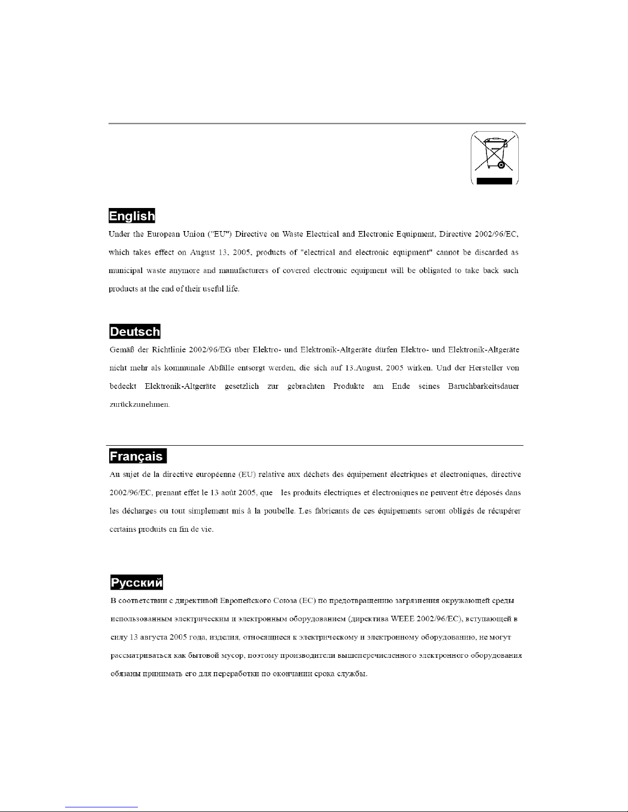
WEEE Statement
vi
vii
viii

CONTENTS
FCC-B Radio Frequency Interference Statement.......................................ii
Trademarks...........................................................................................................iii
Revision History...................................................................................................iii
Safety Instructions..............................................................................................iv
WEEE Statement....................................................................................................vi
Chapter 1. Getting Started................................................................................1-1
Mainboard Specifications....................................................................1-2
Barebone Specifications.....................................................................1-3
Outlook Introduction.............................................................................1-4
Chapter 2. System Assembly..........................................................................2-1
Introduction...........................................................................................2-2
Necessary Tools..................................................................................2-2
The Position of the Key Parts.............................................................2-3
Installing the Mini-PCIE WLAN Card (Optional)..................................2-5
Installing the Floppy Drive / Card Reader Module.............................2-6
Installing the Optical Drive Module......................................................2-9
Installing the Hard Disc Drive (HDD) Module.....................................2-11
Installing the CPU and Thermal Kit......................................................2-13
Installing the Memory Module..............................................................2-16
Installing the Rear Cover (Desk Top Type).........................................2-17
Installing the Rear Cover (Wall Mount Type) (Optional)....................2-19
Chapter 3. BIOS Setup.........................................................................................3-1
Entering Setup.....................................................................................3-2
The Main Menu.....................................................................................3-4
Standard CMOS Features...................................................................3-6
Advanced BIOS Features...................................................................3-8
Advanced Chipset Features...............................................................3-11
Integrated Peripherals..........................................................................3-12
Power Management Setup..................................................................3-16
PNP/PCI Configurations........................................................................3-19
PC Health Status..................................................................................3-20
Load Fail-Safe/Optimized Defaults.....................................................3-21
Set Supervisor/User Password.........................................................3-22
ix


Chapter 1
Getting Started
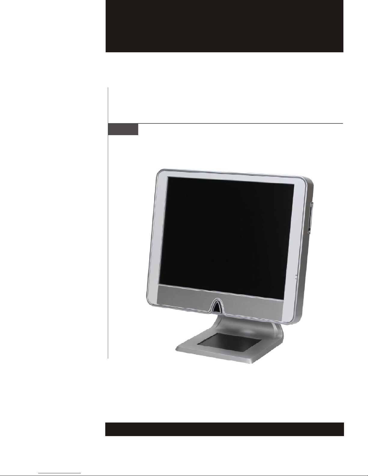
Congratulations for purchasing Crystal A410 (MS-6473)
barebone. Midas barebone is your best Slim PC choice.
With the fantastic appearance and small form factor, it
can easily be set anywhere. The feature packed platform also gives you an exciting PC experience.
MS-6473
Mainboard Specifications
Processor Support
- Intel® Conroe, Conroe-L and Celeron (Ceder Mill) @ 1066MHz FSB
in the LGA 775 package
Chipset
- North Bridge: ATI® RC410M chipset
- South Bridge: ATl® SB600 chipset
Memory Support
- DDR2 533/667 SDRAM (2GB Max)
- 2 DDR2 DIMM slots
LAN
- Supports Ethernet LAN 10/100/1000 by Broadcom® 5787M
Audio
- Azalia HD Codec by Realtek® ALC262
- 2-channel audio
IDE
- Supports Ultra DMA 66/100 mode
LVDS Support
- ATI® RC410M for SDVO to LVDS decoder
Card Bus
- Richo® R5C486
1-2
Barebone Specifications
LCD Panel
- 17” TFT LCD panel
Expansion Slot
- One mini-PCIE slot for WLAN card
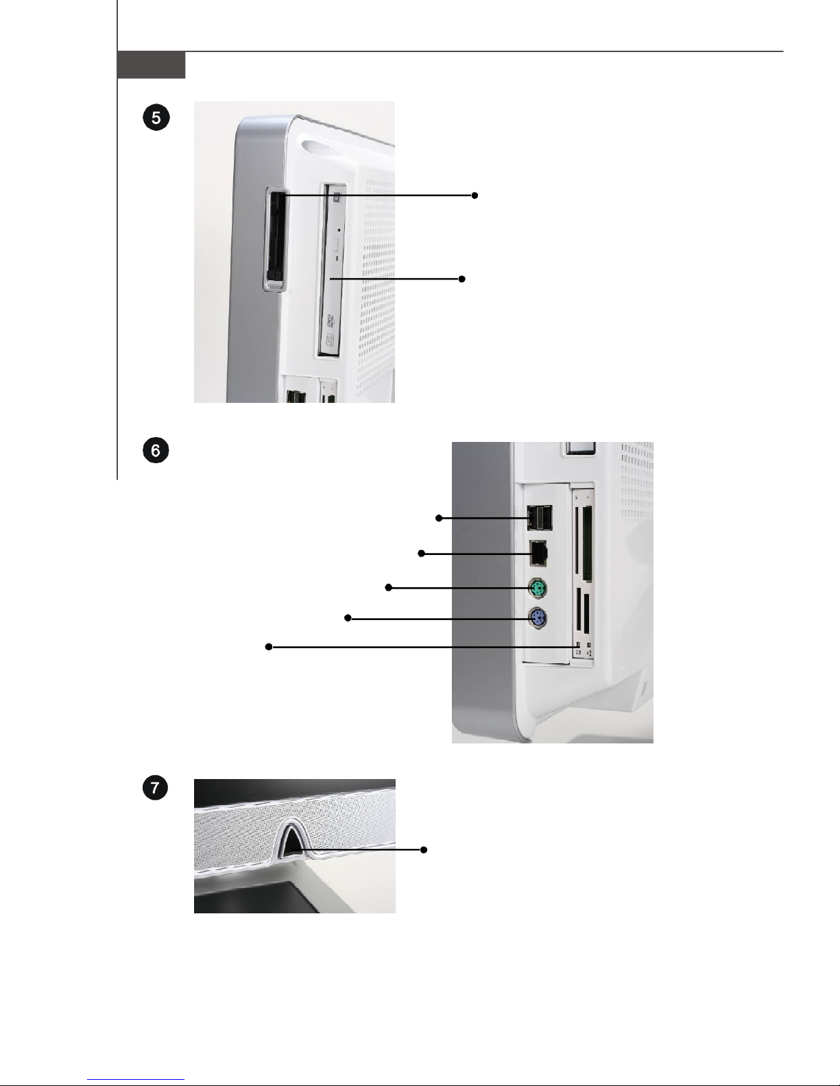
Side I/O
- 1 PS/2 mouse port
- 1 PS/2 keyboard port
- 4 USB 2.0 ports
- 1 LAN jack
- 3 audio jacks (Line-in / Line-out / MIC-in)
- 1 brightness adjustment knob
Bottom I/O
- 1 serial port
- 1 VGA port (D-sub 15)
- 1 parallel port
Getting Started
Power Supply
- 180 Watt PSU
Speaker
- 2 internal speaker with 78dB+3dB @ 1.5W, 0.5M
Drive Bay
- 1 Slim ODD, 2.5” hidden
- 1 Slim FDD / Card reader
Dimension
- 354 mm(H) X 410 mm(W) X 96 mm(D) (without stand)
1-3
MS-6473
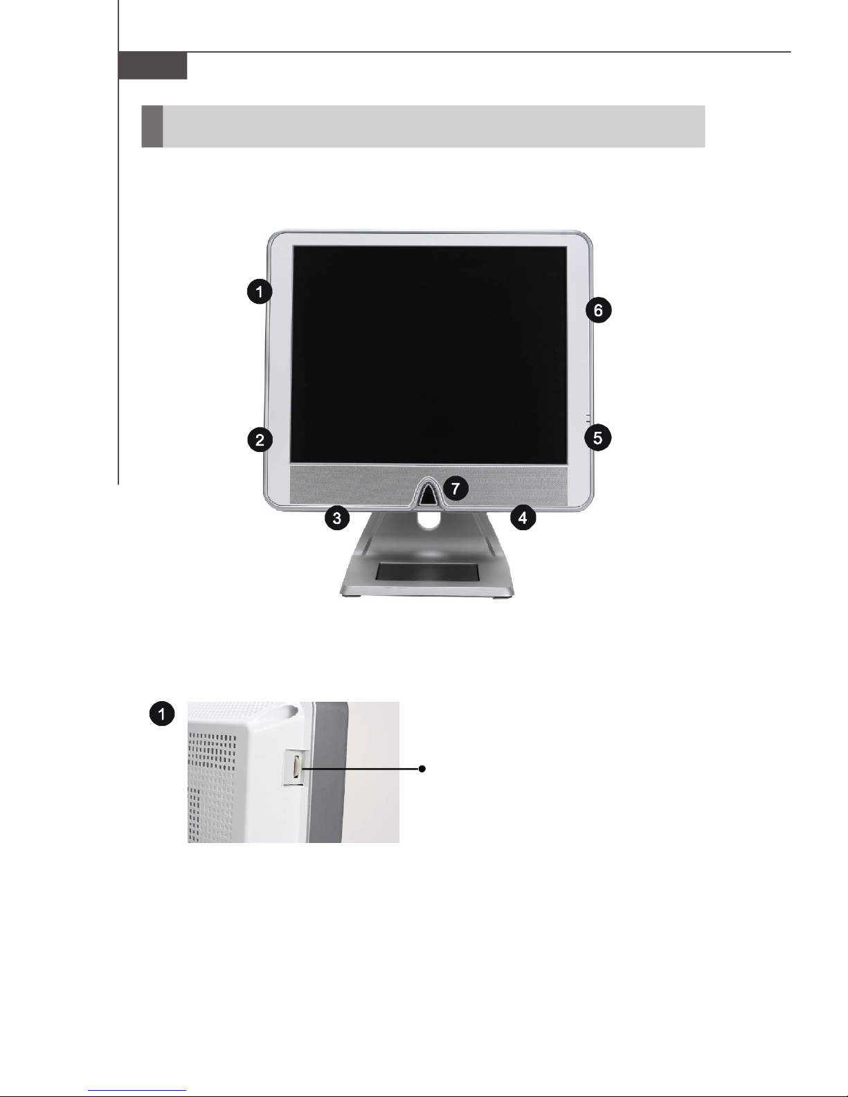
Outlook Introduction
1-4
Brighteness Adjustment Knob
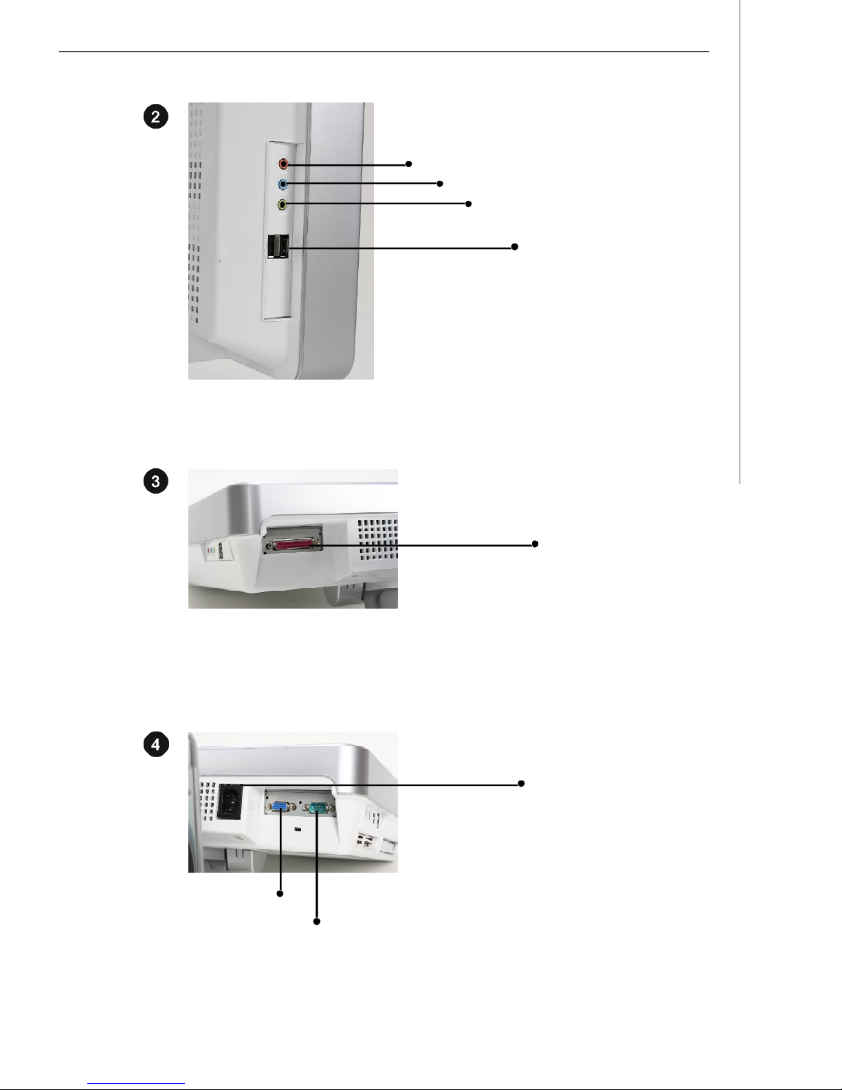
MIC-in
Line-in
Getting Started
Line-out
USB 2.0 Ports
VGA Port
Parallel Port
AC Input Connector
Serial Port
1-5
MS-6473
PCMCIA Card Bus Slot
Optical Storage Drive
PS/2 Mouse Connector
PS/2 Keyboard Connector
Card Reader/
Slim Floppy Drive
(Optional)
USB 2.0 Ports
LAN Jack
Power Switch
1-6

System Assembly
Chapter 2
System Assembly
This chapter provides you with the information about
system assembly procedures. While doing the installation,
be careful in holding the components and follow the
installation procedures.
Use a grounded wrist strap before handling computer
components. Static electricity may damage the
components.
2-1

MS-6473
Introduction
The built-in mainboard is designed for MS-6422 only. Except the mainboard, the
built-in components of the barebone include power supply. In this chapter we’ll show
you how to install CPU and thermal kit, mini-PCI card, card reader, floppy drive, HDD,
optical drive and memory module.
Necessary Tools
Cross type screwdriver, can be used to do most of the
installation. Choose one with a magnetic head would be
better.
Pliers, can be used as an auxiliary tool to connect some
connectors or cables.
Forceps, can be used to pick up tiny screws or set up the
jumpers.
Rubber gloves, can prevent yourself from being incised and
suffering the static charge.
Electric screwdriver, can be used to lock the stand.
2-2
 Loading...